EP1396405A1 - A brake hydraulic pressure controller for a vehicle - Google Patents
A brake hydraulic pressure controller for a vehicle Download PDFInfo
- Publication number
- EP1396405A1 EP1396405A1 EP03018763A EP03018763A EP1396405A1 EP 1396405 A1 EP1396405 A1 EP 1396405A1 EP 03018763 A EP03018763 A EP 03018763A EP 03018763 A EP03018763 A EP 03018763A EP 1396405 A1 EP1396405 A1 EP 1396405A1
- Authority
- EP
- European Patent Office
- Prior art keywords
- electric motor
- hydraulic pressure
- brake
- duty factor
- battery
- Prior art date
- Legal status (The legal status is an assumption and is not a legal conclusion. Google has not performed a legal analysis and makes no representation as to the accuracy of the status listed.)
- Withdrawn
Links
Images



Classifications
-
- B—PERFORMING OPERATIONS; TRANSPORTING
- B60—VEHICLES IN GENERAL
- B60T—VEHICLE BRAKE CONTROL SYSTEMS OR PARTS THEREOF; BRAKE CONTROL SYSTEMS OR PARTS THEREOF, IN GENERAL; ARRANGEMENT OF BRAKING ELEMENTS ON VEHICLES IN GENERAL; PORTABLE DEVICES FOR PREVENTING UNWANTED MOVEMENT OF VEHICLES; VEHICLE MODIFICATIONS TO FACILITATE COOLING OF BRAKES
- B60T8/00—Arrangements for adjusting wheel-braking force to meet varying vehicular or ground-surface conditions, e.g. limiting or varying distribution of braking force
- B60T8/32—Arrangements for adjusting wheel-braking force to meet varying vehicular or ground-surface conditions, e.g. limiting or varying distribution of braking force responsive to a speed condition, e.g. acceleration or deceleration
- B60T8/34—Arrangements for adjusting wheel-braking force to meet varying vehicular or ground-surface conditions, e.g. limiting or varying distribution of braking force responsive to a speed condition, e.g. acceleration or deceleration having a fluid pressure regulator responsive to a speed condition
- B60T8/40—Arrangements for adjusting wheel-braking force to meet varying vehicular or ground-surface conditions, e.g. limiting or varying distribution of braking force responsive to a speed condition, e.g. acceleration or deceleration having a fluid pressure regulator responsive to a speed condition comprising an additional fluid circuit including fluid pressurising means for modifying the pressure of the braking fluid, e.g. including wheel driven pumps for detecting a speed condition, or pumps which are controlled by means independent of the braking system
- B60T8/404—Control of the pump unit
- B60T8/405—Control of the pump unit involving the start-up phase
Definitions
- the present invention relates to a brake hydraulic pressure controller for a vehicle comprising apump for refluxing a brake fluid to a master cylinder, an electric motor which operates to drive the pump by way of power supply from a battery, and a control unit for controlling an energization amount to the electric motor by using an energization duty factor predetermined in accordance with the voltage of the battery.
- Such a brake hydraulic pressure controller for a vehicle is known from the Unexamined Japanese Patent Application Publication No. 2001-71877.
- the above-mentioned brake hydraulic pressure controller for a vehicle performs duty control of the energization amount to the electric motor in accordance with a variation in the battery voltage to reduce the operation sound while limiting the rotation speeds of the electric motor and the pumps so that they will not exceed the necessary values. While a starting torque is necessary to start an electric motor, the starting torque necessary to start the electric motor may not be obtained in the above-mentioned brake hydraulic pressure controller for a vehicle. Conversely, in case a duty factor is determined considering also the start of an electric motor, the steady rotation speed of the electric motor becomes higher than necessary.
- the invention is accomplished in view of the above circumstances and aims at providing a brake hydraulic pressure controller for a vehicle where a start delay of an electric motor is prevented by reducing the operation sound in steady rotation cf the electric motor while obtaining a necessary start torque in starting the electric motor.
- the invention provides a brake hydraulic pressure controller for a vehicle comprising a pump for refluxing a brake fluid to a master cylinder, an electric motor which operates to drive the pump by way of a power supply from a battery, and a control unit for controlling an energization amount to the electric motor by using an energization duty factor predetermined in accordance with the voltage of the battery, characterized in that the control unit keeps the energization duty factor to the electric motor at 100% until a predetermined time elapses and thereafter executes control of the energization duty factor in accordance with the voltage of the battery.
- the energization duty factor of the electric motor is 100% irrespective of the battery voltage.
- the energization amount to the electricinotor is controlled by using the duty factor in accordance with the battery voltage, which prevents the rotation speeds of the electric motor and the pumps from becoming higher than necessary thus reducing the operation sound and saving power consumption.
- Figs. 1 through 5 show an embodiment of the invention.
- Fig. 1 shows a hydraulic circuit of a braking unit for a vehicle.
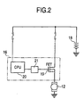
- Fig. 2 shows the configuration of an electric circuit for controlling the rotation speed of an electric motor.
- Fig. 3 shows the energization control mode for the electric motor.
- Fig. 4 shows the relationship between the energization duty factor and the discharge amount using an applied voltage as a parameter in the state where the output hydraulic pressure of a master cylinder is highest.
- Fig. 5 shows a map of the applied voltage and the duty factor.
- a tandem-type master cylinder M comprises a first and a second output port 1A, 1B which each generates a brake hydraulic pressure in accordance with a leg-power a vehicle driver applies on a brake pedal P.
- a brake hydraulic pressure controller 4 is provided between a wheel brake for the left front wheel 2A, wheel brake for the right rear wheel 2B, wheel brake for the right front wheel 2C, wheel brake for the left rear wheel 2D and a first and a second output hydraulic passage 3A, 3B individually connected to the first and second output ports 1A, 1B.
- a first and a second proportional pressure control valve 5A, 5B are respectively interposed between the brake hydraulic pressure controller 4 and the wheel brakes for the right and left rear wheels 2B, 2D.
- the brake hydraulic pressure controller 4 comprises: a first, a second, a third and a fourth normally open solenoid valve 6A through 6D individually corresponding to the wheel brake for the left front wheel 2A, wheel brake for the right rear wheel 2B, wheel brake for the right front wheel 2C and wheel brake for the left rear wheel 2D; a first, a second, a third and a fourth check valve 7A through 7D respectively connected in parallel with the normally open solenoid valves 6A through 6D; a first, a second, a third and a fourth normally closed solenoid valve 8A through 8D individually corresponding to the wheel brakes 2A through 2D; a first and a second reservoir 9A, 9B respectively corresponding to the first and second output hydraulic passages 3A, 3B; a first and a second plunger-type pump 10A, 10B having suction valves 11A, 11B connected to the first and second reservoirs 9A, 9B and discharge valves 13A, 13B; a common electric motor 12 for driving both pumps 10A,
- the first normally open solenoid valve 6A is provided between the first output hydraulic passage 3A and the wheel brake for the left front wheel 2A.
- the second normally open solenoid valve 6B is provided between the first output hydraulic passage 3A and the first proportional pressure control valve 5A.
- the third normally open solenoid valve 6C is provided between the second output hydraulic passage 3B and the wheel brake for the right front wheel 2C.
- the fourth normally open solenoid valve 6D is providedbetween the second output hydraulic passage 3B and the second proportional pressure control valve 5B.
- the first through fourth check valves 7A through 7D are connected in parallel with the normally open solenoid valves 6A through 6D so as to allow the flow of a brake fluid from the corresponding wheel brakes 2A through 2D to the master cylinder M.
- the first normally closed solenoid valve 8A is provided between the wheel brake for the left front wheel 2A and the first reservoir 9A.
- the second normally closed solenoid valve 8B is provided between the first proportional pressure control valve 5A and the first reservoir 9A.
- the third normally closed solenoid valve 8C is provided between the wheel brake for the right front wheel 2C and the second reservoir 9B.
- the fourth normally closed solenoid valve 8D is provided between the second proportional pressure control valve 5B and the second reservoir 9B.
- the brake hydraulic pressure controller 4 communicates the master cylinder M with the wheel brakes 2A through 2D in the steady braking where there is no possibility of lock for each wheel while interrupts the wheel brakes 2A through 2D from the reservoirs 9A, 9B.
- the normally open solenoid valves 6A through 6D are placed in the demagnetized and open state while the normally closed solenoid valves 8A through 8D are placed in the demagnetized and closed state.
- the brake hydraulic pressure output from the first output port 1A of the master cylinder M acts on the wheel brake for the left front wheel 2A via the first normally open solenoid valve 6A as well as acts on the wheel brake for the right rear wheel 2B via the second normally open solenoid valve 6B and the first proportional pressure control valve 5A.
- the brake hydraulic pressure output from the second output port 1B of the master cylinder M acts on the wheel brake for the right front wheel 2C via the third normally open solenoid valve 6C as well as acts on the wheel brake for the left rear wheel 2D via the fourth normally open solenoid valve 6D and the second proportional pressure control valve 5B.
- the brake hydraulic pressure controller 4 interrupts the master cylinder M from the wheel brakes 2A through 2D at a point corresponding to the wheel which is likely to become locked as well as communicates the wheel brakes 2A through 2D with the reservoirs 9A, 9B.
- the normally open solenoid valve out of the first through fourth normally open solenoid valves 6A through 6D corresponding to a wheel which is likely to become locked is magnetized and closed while the normally closed solenoid valve out of the first through fourth normally closed solenoid valves 8A through 8D corresponding to the wheel is magnetized and opened.
- the brake hydraulic pressure controller 4 interrupts the wheel brakes 2A through 2D from the master cylinder M and the reservoirs 9A, 9B.
- the normally open solenoid valves 6A through 6D are magnetized and closed while the normally closed solenoid valves 8A through 8D are demagnetized and closed.
- the normally open solenoid valves 6A through 6D are demagnetized and opened while the normally closed solenoid valves 8A through 8D are demagnetized and closed.
- the power from a battery 18 undergoes energization control by a control unit 16 and then supplied to an electric motor 12.
- the control unit 16 comprises a switching device 12 such as an FET provided between the battery 18 and the electric motor and a CPU 20 for controlling conduction/interruption of the switching device 19 via a booster circuit 21 for boosting a voltage.
- the battery 18 To the CPU 20 is connected the battery 18 to monitor the voltage of the battery 18.
- the CPU controls conduction/interruption of the switching device 19 so that, at the start of the electric motor 12, the energization duty factor to the electric motor 12 is kept at 100% until a predetermined time T, for example 100 ms elapses, and thereafter the energization duty factor in accordance with the voltage of the battery 18 is obtained.
- a drive signal to keep the switching device 19 in conduction is output from the CPU 20. Accordingly, a voltage applied to the electric motor 12 by the battery 18 becomes constant as shown in Fig. 3. A current supplied from the battery 18 to the electric motor 12 varies as shown in Fig. 3.
- the duty factor and the discharge amount whose parameter is the applied voltage in a state where the output hydraulic pressure of the master cylinder M is highest, that is, where the load on the electric motor 12 is maximum have the relationship shown in Fig. 4.
- the energization duty factor to reserve the necessary discharge amount for the pumps 10A, 10B to rotate the electric motor 12 is preset as shown in Fig. 5, based on the relationship shown in Fig. 4.
- the CPU 20 controls conduction/interruption of the switching device 19 so as to perform duty factor control of the energization of the electric motor 12 by the battery 18 by using the energization duty factor which is based on the map of Fig. 5.
- the discharge amounts of the pumps 10A, 10B are suppressed thus reducing the pulsing of the brake fluid back-flow to the master cylinder M. This alleviates the kickback to a brake pedal P in anti-lock braking thus improving the feel of brake operation.
- the energization duty factor of the electric motor 12 is 100% irrespective of voltage of the battery 18.
- the energization duty factor of the electric motor 12 is 100% irrespective of voltage of the battery 18.
Landscapes
- Physics & Mathematics (AREA)
- Fluid Mechanics (AREA)
- Engineering & Computer Science (AREA)
- Transportation (AREA)
- Mechanical Engineering (AREA)
- Regulating Braking Force (AREA)
- Valves And Accessory Devices For Braking Systems (AREA)
Abstract
The control unit (16) keeps the energization duty factor to
the electric motor (12) at 100% until a predetermined time elapses
and thereafter executes control of the energization duty factor
in accordance with the voltage of the battery (18).
Description
- The present invention relates to a brake hydraulic pressure controller for a vehicle comprising apump for refluxing a brake fluid to a master cylinder, an electric motor which operates to drive the pump by way of power supply from a battery, and a control unit for controlling an energization amount to the electric motor by using an energization duty factor predetermined in accordance with the voltage of the battery.
- Such a brake hydraulic pressure controller for a vehicle is known from the Unexamined Japanese Patent Application Publication No. 2001-71877.
- The above-mentioned brake hydraulic pressure controller for a vehicle performs duty control of the energization amount to the electric motor in accordance with a variation in the battery voltage to reduce the operation sound while limiting the rotation speeds of the electric motor and the pumps so that they will not exceed the necessary values. While a starting torque is necessary to start an electric motor, the starting torque necessary to start the electric motor may not be obtained in the above-mentioned brake hydraulic pressure controller for a vehicle. Conversely, in case a duty factor is determined considering also the start of an electric motor, the steady rotation speed of the electric motor becomes higher than necessary.
- The invention is accomplished in view of the above circumstances and aims at providing a brake hydraulic pressure controller for a vehicle where a start delay of an electric motor is prevented by reducing the operation sound in steady rotation cf the electric motor while obtaining a necessary start torque in starting the electric motor.
- In order to attain the above object, the invention provides a brake hydraulic pressure controller for a vehicle comprising a pump for refluxing a brake fluid to a master cylinder, an electric motor which operates to drive the pump by way of a power supply from a battery, and a control unit for controlling an energization amount to the electric motor by using an energization duty factor predetermined in accordance with the voltage of the battery, characterized in that the control unit keeps the energization duty factor to the electric motor at 100% until a predetermined time elapses and thereafter executes control of the energization duty factor in accordance with the voltage of the battery.
- With this configuration, from when the electric motor is started to when the predetermined time elapses, the energization duty factor of the electric motor is 100% irrespective of the battery voltage. Thus it is possible to prevent a start delay of the electric motor by ensuring that a necessary start torque is obtained. When the electric notor reaches a steady rotation by the elapse of the predetermined time, the energization amount to the electricinotor is controlled by using the duty factor in accordance with the battery voltage, which prevents the rotation speeds of the electric motor and the pumps from becoming higher than necessary thus reducing the operation sound and saving power consumption.
-
- Fig. 1 shows a hydraulic circuit of a braking unit for a vehicle;
- Fig. 2 shows the configuration of an electric circuit for controlling the rotation speed of an electric motor;
- Fig. 3 shows the energization control mode for the electric motor;
- Fig. 4 shows the relationship between the energization duty factor and the discharge amount using an applied voltage as a parameter in the state where the output hydraulic pressure of a master cylinder is highest; and
- Fig. 5 shows a map of the applied voltage and the duty factor.
-
- An embodiment of the invention will be described referring to the attached drawings.
- Figs. 1 through 5 show an embodiment of the invention. Fig. 1 shows a hydraulic circuit of a braking unit for a vehicle. Fig. 2 shows the configuration of an electric circuit for controlling the rotation speed of an electric motor. Fig. 3 shows the energization control mode for the electric motor. Fig. 4 shows the relationship between the energization duty factor and the discharge amount using an applied voltage as a parameter in the state where the output hydraulic pressure of a master cylinder is highest. Fig. 5 shows a map of the applied voltage and the duty factor.
- First, in Fig. 1, a tandem-type master cylinder M comprises a first and a
second output port left front wheel 2A, wheel brake for the rightrear wheel 2B, wheel brake for the rightfront wheel 2C, wheel brake for the leftrear wheel 2D and a first and a second outputhydraulic passage second output ports pressure control valve rear wheels - The brake hydraulic pressure controller 4 comprises: a first, a second, a third and a fourth normally
open solenoid valve 6A through 6D individually corresponding to the wheel brake for theleft front wheel 2A, wheel brake for the rightrear wheel 2B, wheel brake for the rightfront wheel 2C and wheel brake for the leftrear wheel 2D; a first, a second, a third and afourth check valve 7A through 7D respectively connected in parallel with the normallyopen solenoid valves 6A through 6D; a first, a second, a third and a fourth normally closedsolenoid valve 8A through 8D individually corresponding to thewheel brakes 2A through 2D; a first and asecond reservoir hydraulic passages type pump suction valves second reservoirs discharge valves electric motor 12 for driving bothpumps orifices pumps hydraulic passages control unit 16 for controlling the operation of the normallyopen solenoid valves 6A through 6D, normally closedsolenoid valves 8A through 8D and theelectric motor 12. - The first normally
open solenoid valve 6A is provided between the first outputhydraulic passage 3A and the wheel brake for theleft front wheel 2A. The second normallyopen solenoid valve 6B is provided between the first outputhydraulic passage 3A and the first proportionalpressure control valve 5A. The third normallyopen solenoid valve 6C is provided between the second outputhydraulic passage 3B and the wheel brake for the rightfront wheel 2C. The fourth normallyopen solenoid valve 6D is providedbetween the second outputhydraulic passage 3B and the second proportionalpressure control valve 5B. - The first through
fourth check valves 7A through 7D are connected in parallel with the normallyopen solenoid valves 6A through 6D so as to allow the flow of a brake fluid from thecorresponding wheel brakes 2A through 2D to the master cylinder M. - The first normally closed
solenoid valve 8A is provided between the wheel brake for theleft front wheel 2A and thefirst reservoir 9A. The second normally closedsolenoid valve 8B is provided between the first proportionalpressure control valve 5A and thefirst reservoir 9A. The third normally closedsolenoid valve 8C is provided between the wheel brake for the rightfront wheel 2C and thesecond reservoir 9B. The fourth normally closedsolenoid valve 8D is provided between the second proportionalpressure control valve 5B and thesecond reservoir 9B. - The brake hydraulic pressure controller 4 communicates the master cylinder M with the
wheel brakes 2A through 2D in the steady braking where there is no possibility of lock for each wheel while interrupts thewheel brakes 2A through 2D from thereservoirs open solenoid valves 6A through 6D are placed in the demagnetized and open state while the normally closedsolenoid valves 8A through 8D are placed in the demagnetized and closed state. The brake hydraulic pressure output from thefirst output port 1A of the master cylinder M acts on the wheel brake for theleft front wheel 2A via the first normallyopen solenoid valve 6A as well as acts on the wheel brake for the rightrear wheel 2B via the second normallyopen solenoid valve 6B and the first proportionalpressure control valve 5A. The brake hydraulic pressure output from thesecond output port 1B of the master cylinder M acts on the wheel brake for the rightfront wheel 2C via the third normallyopen solenoid valve 6C as well as acts on the wheel brake for the leftrear wheel 2D via the fourth normally opensolenoid valve 6D and the second proportionalpressure control valve 5B. - When a wheel which is likely to become locked in the above braking, the brake hydraulic pressure controller 4 interrupts the master cylinder M from the
wheel brakes 2A through 2D at a point corresponding to the wheel which is likely to become locked as well as communicates thewheel brakes 2A through 2D with thereservoirs open solenoid valves 6A through 6D corresponding to a wheel which is likely to become locked is magnetized and closed while the normally closed solenoid valve out of the first through fourth normally closedsolenoid valves 8A through 8D corresponding to the wheel is magnetized and opened. With this process, part of the brake hydraulic pressure of the wheel which is likely to become locked is absorbed in thefirst reservoir 9A orsecond reservoir 9B thereby reducing the brake hydraulic pressure of the wheel which is likely to become locked. - To keep the brake hydraulic pressure constant, the brake hydraulic pressure controller 4 interrupts the
wheel brakes 2A through 2D from the master cylinder M and thereservoirs open solenoid valves 6A through 6D are magnetized and closed while the normally closedsolenoid valves 8A through 8D are demagnetized and closed. When the brake hydraulic pressure is increased, the normallyopen solenoid valves 6A through 6D are demagnetized and opened while the normally closedsolenoid valves 8A through 8D are demagnetized and closed. - In this way, by controlling demagnetization and magnetization of the normally
open solenoid valves 6A through 6D and the normally closedsolenoid valves 8A through 8D, it is possible to control the wheels without locking them. - In Fig. 2, the power from a
battery 18 undergoes energization control by acontrol unit 16 and then supplied to anelectric motor 12. Thecontrol unit 16 comprises aswitching device 12 such as an FET provided between thebattery 18 and the electric motor and aCPU 20 for controlling conduction/interruption of theswitching device 19 via abooster circuit 21 for boosting a voltage. - To the
CPU 20 is connected thebattery 18 to monitor the voltage of thebattery 18. The CPU controls conduction/interruption of theswitching device 19 so that, at the start of theelectric motor 12, the energization duty factor to theelectric motor 12 is kept at 100% until a predetermined time T, for example 100 ms elapses, and thereafter the energization duty factor in accordance with the voltage of thebattery 18 is obtained. - As shown in Fig. 3, from when the
electric motor 12 is started to when the predetermined time T elapses, a drive signal to keep theswitching device 19 in conduction is output from theCPU 20. Accordingly, a voltage applied to theelectric motor 12 by thebattery 18 becomes constant as shown in Fig. 3. A current supplied from thebattery 18 to theelectric motor 12 varies as shown in Fig. 3. - To control the energization of the
electric motor 12 by using an energization duty factor in accordance with the voltage of thebattery 18 after the predetermined time T elapses since the start of theelectric motor 12, the duty factor and the discharge amount whose parameter is the applied voltage in a state where the output hydraulic pressure of the master cylinder M is highest, that is, where the load on theelectric motor 12 is maximum have the relationship shown in Fig. 4. The energization duty factor to reserve the necessary discharge amount for thepumps electric motor 12 is preset as shown in Fig. 5, based on the relationship shown in Fig. 4. TheCPU 20 controls conduction/interruption of theswitching device 19 so as to perform duty factor control of the energization of theelectric motor 12 by thebattery 18 by using the energization duty factor which is based on the map of Fig. 5. - The operation of this embodiment will be described. In the steady rotation after the predetermined time T elapses since the start of the
electric motor 12 in initial diagnosis or in operating theelectric motor 12 to control an anti-lock brake, conduction/interruption of theswitching device 19 is controlled to control the energization amount of theelectric motor 12 so that the energization duty factor in accordance with the voltage of thebattery 18 will be obtained. This makes it possible to keep relatively low rotation speeds of theelectric motor 12 and thepumps electric motor 12 and thepumps - The discharge amounts of the
pumps - Further, from when the
electric motor 12 is started to when the predetermined time T elapses, the energization duty factor of theelectric motor 12 is 100% irrespective of voltage of thebattery 18. Thus it is possible to prevent a start delay of theelectric motor 12 by ensuring that a necessary start torque is obtained. - While the embodiments of the invention are described hereinabove, the invention is not limited to the foregoing embodiments. Various design changes can be made in the invention without departing from the spirit and scope defined in the claims.
- As mentioned hereinabove, according to the invention, it is possible to prevent a start delay of an electric motor by ensuring that a necessary start torque is obtained. When the electric motor reaches steady rotation, it is possible to prevent the rotation speeds of the electric motor and the pumps from becoming higher than necessary thus reducing the operation sound and saving power consumption.
Claims (2)
- A brake hydraulic pressure controller for a vehicle comprising:a pump for refluxing a brake fluid to a master cylinder,an electric motor which operates to drive said pump by way of a power supply from a battery, anda control unit for controlling an energization amount to said electric motor by using an energization duty factor predetermined in accordance with the voltage of said battery, whereinsaid control unit keeps the energization duty factor to said electric motor at 100% until a predetermined time elapses, and thereafter executes control of the energization duty factor in accordance with the voltage of said battery.
- The brake hydraulic pressure controller for a vehicle according to the claim 1, wherein
the predetermined time is 100 msec.
Applications Claiming Priority (2)
| Application Number | Priority Date | Filing Date | Title |
|---|---|---|---|
| JP2002246732A JP2004082870A (en) | 2002-08-27 | 2002-08-27 | Vehicle brake fluid pressure control device |
| JP2002246732 | 2002-08-27 |
Publications (1)
| Publication Number | Publication Date |
|---|---|
| EP1396405A1 true EP1396405A1 (en) | 2004-03-10 |
Family
ID=31712239
Family Applications (1)
| Application Number | Title | Priority Date | Filing Date |
|---|---|---|---|
| EP03018763A Withdrawn EP1396405A1 (en) | 2002-08-27 | 2003-08-27 | A brake hydraulic pressure controller for a vehicle |
Country Status (3)
| Country | Link |
|---|---|
| US (1) | US6925801B2 (en) |
| EP (1) | EP1396405A1 (en) |
| JP (1) | JP2004082870A (en) |
Families Citing this family (4)
| Publication number | Priority date | Publication date | Assignee | Title |
|---|---|---|---|---|
| JP4847893B2 (en) * | 2007-02-27 | 2011-12-28 | 日信工業株式会社 | Brake hydraulic pressure control device for bar handle vehicle |
| JP5563004B2 (en) * | 2012-03-28 | 2014-07-30 | 日信工業株式会社 | Brake hydraulic pressure control device for vehicles |
| JP6762230B2 (en) * | 2016-12-28 | 2020-09-30 | ダイムラー・アクチェンゲゼルシャフトDaimler AG | Electric vacuum pump control device and electric vacuum pump control method |
| EP4382324A3 (en) * | 2022-11-21 | 2024-08-14 | BeijingWest Industries Co. Ltd. | Independent corner lift system for vehicles |
Citations (6)
| Publication number | Priority date | Publication date | Assignee | Title |
|---|---|---|---|---|
| JPS61150858A (en) * | 1984-12-25 | 1986-07-09 | Nippon Denso Co Ltd | Motor drive device for driving antiskid actuator |
| US5295737A (en) * | 1990-11-22 | 1994-03-22 | Robert Bosch Gmbh | Electric motor-driven hydraulic pump |
| DE4408879A1 (en) * | 1994-03-16 | 1995-09-21 | Bayerische Motoren Werke Ag | Brake circuit with motor for hydraulic pump |
| US5487593A (en) * | 1994-11-23 | 1996-01-30 | Alliedsignal Inc. | Anti-lock braking system providing pump motor duty cycle based on deceleration and motor voltage feed back |
| EP0982207A2 (en) * | 1998-08-28 | 2000-03-01 | Toyota Jidosha Kabushiki Kaisha | Apparatus for increasing brake cylinder pressure by controlling pump motor and reducing the pressure by controlling electric energy applied to control valve |
| US20020101114A1 (en) * | 2001-01-31 | 2002-08-01 | Masahiko Kamiya | Vehicle brake fluid pressure control device with hydraulic booster |
Family Cites Families (2)
| Publication number | Priority date | Publication date | Assignee | Title |
|---|---|---|---|---|
| US10004A (en) * | 1853-09-06 | Improvement in iron car-brakes | ||
| JP2001071877A (en) * | 1999-09-09 | 2001-03-21 | Nissin Kogyo Co Ltd | Anti-lock brake control device for vehicles |
-
2002
- 2002-08-27 JP JP2002246732A patent/JP2004082870A/en active Pending
-
2003
- 2003-08-26 US US10/647,508 patent/US6925801B2/en not_active Expired - Lifetime
- 2003-08-27 EP EP03018763A patent/EP1396405A1/en not_active Withdrawn
Patent Citations (6)
| Publication number | Priority date | Publication date | Assignee | Title |
|---|---|---|---|---|
| JPS61150858A (en) * | 1984-12-25 | 1986-07-09 | Nippon Denso Co Ltd | Motor drive device for driving antiskid actuator |
| US5295737A (en) * | 1990-11-22 | 1994-03-22 | Robert Bosch Gmbh | Electric motor-driven hydraulic pump |
| DE4408879A1 (en) * | 1994-03-16 | 1995-09-21 | Bayerische Motoren Werke Ag | Brake circuit with motor for hydraulic pump |
| US5487593A (en) * | 1994-11-23 | 1996-01-30 | Alliedsignal Inc. | Anti-lock braking system providing pump motor duty cycle based on deceleration and motor voltage feed back |
| EP0982207A2 (en) * | 1998-08-28 | 2000-03-01 | Toyota Jidosha Kabushiki Kaisha | Apparatus for increasing brake cylinder pressure by controlling pump motor and reducing the pressure by controlling electric energy applied to control valve |
| US20020101114A1 (en) * | 2001-01-31 | 2002-08-01 | Masahiko Kamiya | Vehicle brake fluid pressure control device with hydraulic booster |
Non-Patent Citations (1)
| Title |
|---|
| PATENT ABSTRACTS OF JAPAN vol. 010, no. 353 (M - 539) 28 November 1986 (1986-11-28) * |
Also Published As
| Publication number | Publication date |
|---|---|
| US20040040298A1 (en) | 2004-03-04 |
| JP2004082870A (en) | 2004-03-18 |
| US6925801B2 (en) | 2005-08-09 |
Similar Documents
| Publication | Publication Date | Title |
|---|---|---|
| JP4595941B2 (en) | Vehicle braking force control device | |
| JP3828609B2 (en) | Anti-lock brake device | |
| JPS63154456A (en) | Wheel lock preventing device | |
| JP3992009B2 (en) | Brake device | |
| JPS63159169A (en) | Wheel lock preventing device | |
| EP1083102A1 (en) | Vehicle anti-lock brake control system | |
| US6925801B2 (en) | Brake hydraulic pressure controller for a vehicle | |
| JP4502826B2 (en) | Brake device for vehicle | |
| US20060175895A1 (en) | Hydraulic brake system with anti-lock control | |
| JP3249564B2 (en) | Pump motor supply voltage control device and pump motor supply voltage control method in anti-skid brake control device | |
| JP2616191B2 (en) | Reflux type anti-lock brake system | |
| JP3887307B2 (en) | Electric motor drive device | |
| JP2005231395A (en) | Brake hydraulic pressure control device | |
| JP3035968B2 (en) | Anti-skid control device | |
| JP2004217155A (en) | Vehicle brake control device | |
| JP2010089626A (en) | Drag preventing method in brake device for vehicle | |
| JP2001071881A (en) | Brake fluid pressure source device | |
| JPH1081223A (en) | Brake control device | |
| JP2000255401A (en) | Brake system | |
| JP2001071892A (en) | Motor control method in anti-lock brake control device for vehicle | |
| JP4622008B2 (en) | Brake hydraulic pressure control device | |
| JPH07222472A (en) | Drive controller for electric motor for hydraulic brake system | |
| JPH1076929A (en) | Anti-skid control device | |
| JPH11152030A (en) | Hydraulic brake device | |
| JP2000095090A (en) | Hydraulic brake device |
Legal Events
| Date | Code | Title | Description |
|---|---|---|---|
| PUAI | Public reference made under article 153(3) epc to a published international application that has entered the european phase |
Free format text: ORIGINAL CODE: 0009012 |
|
| AK | Designated contracting states |
Kind code of ref document: A1 Designated state(s): AT BE BG CH CY CZ DE DK EE ES FI FR GB GR HU IE IT LI LU MC NL PT RO SE SI SK TR |
|
| AX | Request for extension of the european patent |
Extension state: AL LT LV MK |
|
| 17P | Request for examination filed |
Effective date: 20040629 |
|
| 17Q | First examination report despatched |
Effective date: 20040913 |
|
| AKX | Designation fees paid |
Designated state(s): DE GB |
|
| STAA | Information on the status of an ep patent application or granted ep patent |
Free format text: STATUS: THE APPLICATION IS DEEMED TO BE WITHDRAWN |
|
| 18D | Application deemed to be withdrawn |
Effective date: 20050125 |