EP1396358B1 - Compound steering mechanism - Google Patents
Compound steering mechanism Download PDFInfo
- Publication number
- EP1396358B1 EP1396358B1 EP03016785A EP03016785A EP1396358B1 EP 1396358 B1 EP1396358 B1 EP 1396358B1 EP 03016785 A EP03016785 A EP 03016785A EP 03016785 A EP03016785 A EP 03016785A EP 1396358 B1 EP1396358 B1 EP 1396358B1
- Authority
- EP
- European Patent Office
- Prior art keywords
- axle
- steerable
- casing
- assembly according
- flexible coupling
- Prior art date
- Legal status (The legal status is an assumption and is not a legal conclusion. Google has not performed a legal analysis and makes no representation as to the accuracy of the status listed.)
- Expired - Lifetime
Links
- 230000007246 mechanism Effects 0.000 title description 17
- 150000001875 compounds Chemical class 0.000 title description 14
- 230000008878 coupling Effects 0.000 claims abstract 17
- 238000010168 coupling process Methods 0.000 claims abstract 17
- 238000005859 coupling reaction Methods 0.000 claims abstract 17
- 238000004519 manufacturing process Methods 0.000 description 3
- 230000004048 modification Effects 0.000 description 3
- 238000012986 modification Methods 0.000 description 3
- 239000000725 suspension Substances 0.000 description 3
- 230000007423 decrease Effects 0.000 description 2
- 230000003247 decreasing effect Effects 0.000 description 2
- 210000000988 bone and bone Anatomy 0.000 description 1
- 230000000694 effects Effects 0.000 description 1
- 239000002184 metal Substances 0.000 description 1
Images




Classifications
-
- B—PERFORMING OPERATIONS; TRANSPORTING
- B60—VEHICLES IN GENERAL
- B60G—VEHICLE SUSPENSION ARRANGEMENTS
- B60G9/00—Resilient suspensions of a rigid axle or axle housing for two or more wheels
- B60G9/02—Resilient suspensions of a rigid axle or axle housing for two or more wheels the axle or housing being pivotally mounted on the vehicle, e.g. the pivotal axis being parallel to the longitudinal axis of the vehicle
-
- B—PERFORMING OPERATIONS; TRANSPORTING
- B62—LAND VEHICLES FOR TRAVELLING OTHERWISE THAN ON RAILS
- B62D—MOTOR VEHICLES; TRAILERS
- B62D7/00—Steering linkage; Stub axles or their mountings
- B62D7/06—Steering linkage; Stub axles or their mountings for individually-pivoted wheels, e.g. on king-pins
-
- B—PERFORMING OPERATIONS; TRANSPORTING
- B62—LAND VEHICLES FOR TRAVELLING OTHERWISE THAN ON RAILS
- B62D—MOTOR VEHICLES; TRAILERS
- B62D9/00—Steering deflectable wheels not otherwise provided for
-
- B—PERFORMING OPERATIONS; TRANSPORTING
- B60—VEHICLES IN GENERAL
- B60G—VEHICLE SUSPENSION ARRANGEMENTS
- B60G2200/00—Indexing codes relating to suspension types
- B60G2200/30—Rigid axle suspensions
- B60G2200/32—Rigid axle suspensions pivoted
-
- B—PERFORMING OPERATIONS; TRANSPORTING
- B60—VEHICLES IN GENERAL
- B60G—VEHICLE SUSPENSION ARRANGEMENTS
- B60G2200/00—Indexing codes relating to suspension types
- B60G2200/30—Rigid axle suspensions
- B60G2200/34—Stabilising mechanisms, e.g. for lateral stability
-
- B—PERFORMING OPERATIONS; TRANSPORTING
- B60—VEHICLES IN GENERAL
- B60G—VEHICLE SUSPENSION ARRANGEMENTS
- B60G2200/00—Indexing codes relating to suspension types
- B60G2200/40—Indexing codes relating to the wheels in the suspensions
- B60G2200/44—Indexing codes relating to the wheels in the suspensions steerable
-
- B—PERFORMING OPERATIONS; TRANSPORTING
- B60—VEHICLES IN GENERAL
- B60G—VEHICLE SUSPENSION ARRANGEMENTS
- B60G2204/00—Indexing codes related to suspensions per se or to auxiliary parts
- B60G2204/40—Auxiliary suspension parts; Adjustment of suspensions
- B60G2204/422—Links for mounting suspension elements
-
- B—PERFORMING OPERATIONS; TRANSPORTING
- B60—VEHICLES IN GENERAL
- B60G—VEHICLE SUSPENSION ARRANGEMENTS
- B60G2300/00—Indexing codes relating to the type of vehicle
- B60G2300/08—Agricultural vehicles
- B60G2300/082—Tractors
Definitions
- This invention relates to steering mechanisms for off highway vehicles, and in particular steering mechanisms for tractors permitting a decreased turning radius for the tractor.
- tractors whatever their application typically comprise a non steerable driven axle, and a steerable axle, the wheels of which may or may not be driven.
- the steerable axle is pivotally mounted to the tractor chassis to pivot about a generally horizontal axis.
- the front axle is thereby permitted to oscillate with respect to the chassis, so that the wheel may stay in contact with uneven ground.
- Physical constraints are imposed on the range of movement of the steerable wheels. Physical constraints include tyre size, track setting, clearance between chassis and the end of the axle etc.
- the maximum turning angle provides the smallest turning diameter for any particular tractor set up. In order to increase manoeuvreability of the tractor, designers have sought to increase the turning angle.
- a decreased turning radius is achieved by moving the steering axle relative to the chassis at the same time as turning the steering wheels.
- the turning angle may be increased in two ways. First, in many compound steering mechanisms the axle move through an arc so that instead of extending at 90 degrees to the longitudinal axis of the tractor, and direction of travel it extends of between 80 - 90 degrees to the direction of travel, depending on the direction of the steerable wheels. Second, by moving the axle relative to the chassis, the distance between an inner steerable wheel and the chassis is increased thereby permitting the maximum angle of the inner steerable wheel and the front axle to be increased.
- the arrangement comprises a tubular drag link which at one end is rigidly attached to the steering axle, and at its other end is attached to the tractor chassis by means of a ball joint, the ball joint being rearward of the steering axle.
- the maximum turning angle is further enhanced by positioning the steerable axle such that during a turn the front of the tractor chassis.
- the practice of positioning the front axle such that during a turn the front of the outside turning wheel moves in front of the front end of the tractor chassis is not unique to compound steering arrangement. Many agricultural tractors have this feature.
- the front of the steerable axle is also connected to the tractor chassis by either a pair of pivotable springs or a control arm.
- European Patent 0400033 requires a costly tubular pole type drag link and modification to the tractor chassis to accommodate said drag link. Furthermore, the length of the drag link places design limitations on the provision of drive to the front axle. Also, the length of the drag link may improve stability problems.
- axle mounting assembly which provides for compound steering.
- the assembly comprises a front axle support 1.
- the front axle support 1 is cast in metal.
- the front axle support 1 includes a rear wall 5 having a plurality of apertures 6.
- the front axle 1 support is attached to the next component of the vehicle chassis (which may be a subframe or the stressed sump of an engine) by means of bolts or pins passing through said aperture 6.
- the front end of the front axle support includes a housing 2 which includes a ball portion 4 of a ball and socket joint, the socket part 17 of said joint being formed in one end of a wishbone 16.
- the axle 8 comprises an axle casing 20 on the ends of which are mounted steerable wheel hubs 23, said hubs 23 being mounted on said axle casing by king pins 22.
- the ball part 13 of the joint being arranged on a mount 12 extending from an input drive shaft housing 11, which supports an input shaft 18 (see Figures 6 and 7) and is itself attached to an axle casing 20.
- Shaft 18 is substantially aligned with the longitudinal axis of the associated tractor when the wheels are in the straight ahead position and drives the wheel hubs 23.
- a mount 9 extends forward from the front face of the axle casing 20 and mounts the ball part 10 of a ball and socket joint.
- the socket part 17 of the joint is formed in the other end of the previously mentioned wishbone 16.
- each ball and socket joint includes an elastically compressible member, such as a rubber block.
- the front axle support 1 has attached thereto a first bracket 27 to which is attached one end of a link 25.
- the other end of the link 25 is attached to a second bracket 24 which is itself attached to the steerable wheel hub mount 28.
- Brackets 29 are also attached to the steerable wheel hub mount 28.
- One end of a track rod 15 is attached to a bracket 29 by a ball and socket joint 21, with the other end of the track rod 15 being attached to a piston of a hydraulically actuated piston and cylinder steering ram 14.
- Figure 3 illustrates the exemplary mounting axle assembly executing right turn. It can be seen that the axis Y-Y of the steerable axle 8 has moved from being substantially perpendicular to the longitudinal axis of the front axle support 1 to being anglarly displaced with respect to said longitudinal axis.
- the centre point Z of the axle 8 has moved sideways to the right, as compared to Figure 2, where the wheels are set to provide a substantially straight travel path.
- This sideways movement of the axle 8 is caused by the link 25 which is substantially rigid.
- the wheel hub 23 and its mount 29 pivot about the king pin 22 causing the bracket 24 to move through an arc. Since both the links 25 and bracket 24 are substantially rigid, the distance between the bracket 27 and the king pin 22 must increase, thereby shifting the axle 8 sideways.
- Figure 5 illustrates how the wishbone 16 moves during a turn. Also, it can be understood from Figure 5 that as the axle 8 moves away from the central position shown in Figure 4 to that shown in Figure 5, the distance between the axle 8 and the axle support 1 decreases.
- FIG. 8 to 10 of the drawings is a modification providing a front axle suspension.
- the rigid wishbone 16 is replaced by a suspension member 30, the suspension member comprising a damper 31, opposite ends of which comprise sockets 32 which co-operate with ball parts 4, 10 in the same manner as described with reference to Figures 1 to 7.
- Each of the two halves of the damper 31 comprises a spring retaining member 33 with a coil spring 34 being located between said members 33 and around the damper 31.
- links 25 may be of a type which can be adjusted in length either manually or hydraulically. Such types of link are well known in the art and may be required to provide for adjustments to track width or tyre size.
- the invention provides a very simple arrangement which is self contained insofar as all the components of the assembly are mounted on the axle support. As such very little modification to the vehicle is required. Also, very few components are used, resulting in the assembly being relatively inexpensive to manufacture and maintain.
Landscapes
- Engineering & Computer Science (AREA)
- Mechanical Engineering (AREA)
- Chemical & Material Sciences (AREA)
- Combustion & Propulsion (AREA)
- Transportation (AREA)
- Steering-Linkage Mechanisms And Four-Wheel Steering (AREA)
- Vehicle Body Suspensions (AREA)
- Power Steering Mechanism (AREA)
- Axle Suspensions And Sidecars For Cycles (AREA)
Abstract
Description
- This invention relates to steering mechanisms for off highway vehicles, and in particular steering mechanisms for tractors permitting a decreased turning radius for the tractor.
- Most tractors, whatever their application typically comprise a non steerable driven axle, and a steerable axle, the wheels of which may or may not be driven.
- In a typical arrangement the steerable axle is pivotally mounted to the tractor chassis to pivot about a generally horizontal axis. The front axle is thereby permitted to oscillate with respect to the chassis, so that the wheel may stay in contact with uneven ground.
- A number of physical constraints are imposed on the range of movement of the steerable wheels. Physical constraints include tyre size, track setting, clearance between chassis and the end of the axle etc.
- The maximum turning angle provides the smallest turning diameter for any particular tractor set up. In order to increase manoeuvreability of the tractor, designers have sought to increase the turning angle.
- One solution to the problem of increasing turning axle has become known generally as compound steering. In a compound steering mechanism a decreased turning radius is achieved by moving the steering axle relative to the chassis at the same time as turning the steering wheels. By moving the axle relative to the chassis, the turning angle may be increased in two ways. First, in many compound steering mechanisms the axle move through an arc so that instead of extending at 90 degrees to the longitudinal axis of the tractor, and direction of travel it extends of between 80 - 90 degrees to the direction of travel, depending on the direction of the steerable wheels. Second, by moving the axle relative to the chassis, the distance between an inner steerable wheel and the chassis is increased thereby permitting the maximum angle of the inner steerable wheel and the front axle to be increased.
- An example of a compound steering mechanism is found in US 5046577. In the steering mechanism described in US 5046577, when the steerable wheels are turned relative to the steering axle simultaneously, the steering axle pivots relative to the chassis. A connecting link interconnects the pivot mechanism which pivotally connects the steering axle to the chassis, with the steering mechanism such that manipulation of the steering mechanism effects a turning of the wheels and a pivotal movement of the steering axle in the same direction the wheels are being turned. The pivot mechanism allows for pivotal movement of the steering axle about a longitudinally extending horizontal axis in addition to the pivotal movement of the steering axle about a generally vertical axis relative to the chassis. A lost motion linkage interconnecting the pivot mechanism and the steering axle accommodates differences in arcuate movements due to the pivot mechanism and the steering axle pivotally moving about longitudinally spaced pivot centres.
- The compound steering mechanism of US 5046577 is complex requiring a number of moving parts. Such a mechanism is both costly to manufacture and maintain.
- Another compound steering arrangement is described in US 5312123. In the compound steering arrangement described in this patent a steering axle is mounted on one surface which carries a vertical pivot and a ball joint which is connected to the tractor rearwardly of the steering axle. The front of the subframe is attached to the tractor by a yoke comprising a carrier member pivotally attached to the tractor and a pair of dog bone links, each link being attached to the carrier member and the axle. The assembly provides for pivotal movement of the steering axle relative to the chassis by a four bar linkage so that the tractor chassis maintains a substantially uniform elevation relative to the steering axle throughout the range of movement of the steerable axle. This compound steering mechanism requires many moving component parts and as such is expensive to manufacture and maintain.
- Another compound steering arrangement is described in European Patent 0400033. The arrangement comprises a tubular drag link which at one end is rigidly attached to the steering axle, and at its other end is attached to the tractor chassis by means of a ball joint, the ball joint being rearward of the steering axle. The maximum turning angle is further enhanced by positioning the steerable axle such that during a turn the front of the tractor chassis. The practice of positioning the front axle such that during a turn the front of the outside turning wheel moves in front of the front end of the tractor chassis is not unique to compound steering arrangement. Many agricultural tractors have this feature.
- The front of the steerable axle is also connected to the tractor chassis by either a pair of pivotable springs or a control arm.
- The arrangement described is European Patent 0400033 requires a costly tubular pole type drag link and modification to the tractor chassis to accommodate said drag link. Furthermore, the length of the drag link places design limitations on the provision of drive to the front axle. Also, the length of the drag link may improve stability problems.
- It would therefore be desirable to provide an improved compound steering mechanism.
- In the drawings which illustrate a preferred embodiment of the invention, by way of example only:
- Figure 1 is a side view in partial cross-section of an assembly according to an embodiment of the invention;
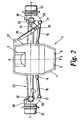
- Figure 2 is a plan view of an assembly according to an embodiment of the invention;
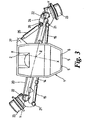
- Figure 3 is a plan view of the assembly shown in Figure 2, with the steering wheels turned through an angle;
- Figure 4 is a front view of the assembly shown in Figure 2;
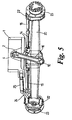
- Figure 5 is the front view of the assembly shown in Figure 3;
- Figure 6 is a view of the underside of the assembly show in Figure 2;
- Figure 7 is a view of the underside of the assembly shown in Figure 3;
- Figure 8 is a side view in partial cross-section of an assembly according to the embodiment of the invention;
- Figure 9 is a front view of the assembly shown in Figure 8;
- Figure 10 is a view of the embodiment shown in Figure 9 with the steering wheels turned through an angle.
- Referring to Figure 1, there is shown an axle mounting assembly, which provides for compound steering.
- The assembly comprises a front axle support 1. In the example the front axle support 1 is cast in metal.
- The front axle support 1 includes a
rear wall 5 having a plurality ofapertures 6. The front axle 1 support is attached to the next component of the vehicle chassis (which may be a subframe or the stressed sump of an engine) by means of bolts or pins passing through saidaperture 6. - The front end of the front axle support includes a
housing 2 which includes a ball portion 4 of a ball and socket joint, thesocket part 17 of said joint being formed in one end of awishbone 16. - The axle 8 comprises an
axle casing 20 on the ends of which are mountedsteerable wheel hubs 23, saidhubs 23 being mounted on said axle casing byking pins 22. - To the rear of the front axle support 1, and on the underside thereof there is located the
socket part 3 of a ball and socket joint theball part 13 of the joint being arranged on amount 12 extending from an inputdrive shaft housing 11, which supports an input shaft 18 (see Figures 6 and 7) and is itself attached to anaxle casing 20. -
Shaft 18 is substantially aligned with the longitudinal axis of the associated tractor when the wheels are in the straight ahead position and drives thewheel hubs 23. - A mount 9 extends forward from the front face of the
axle casing 20 and mounts theball part 10 of a ball and socket joint. Thesocket part 17 of the joint is formed in the other end of the previously mentionedwishbone 16. - Preferably each ball and socket joint includes an elastically compressible member, such as a rubber block.
- The manner in which the compound steering arrangement functions will now be described with reference to Figures 1 to 6.
- Looking first at Figure 2, the front axle support 1 has attached thereto a
first bracket 27 to which is attached one end of alink 25. The other end of thelink 25 is attached to asecond bracket 24 which is itself attached to the steerablewheel hub mount 28. - Also attached to the steerable
wheel hub mount 28 arebrackets 29. One end of atrack rod 15 is attached to abracket 29 by a ball and socket joint 21, with the other end of thetrack rod 15 being attached to a piston of a hydraulically actuated piston andcylinder steering ram 14. Figure 3 illustrates the exemplary mounting axle assembly executing right turn. It can be seen that the axis Y-Y of the steerable axle 8 has moved from being substantially perpendicular to the longitudinal axis of the front axle support 1 to being anglarly displaced with respect to said longitudinal axis. - Furthermore, the centre point Z of the axle 8 has moved sideways to the right, as compared to Figure 2, where the wheels are set to provide a substantially straight travel path. This sideways movement of the axle 8 is caused by the
link 25 which is substantially rigid. As thearm 15 is moved to the left, thewheel hub 23 and itsmount 29 pivot about theking pin 22 causing thebracket 24 to move through an arc. Since both thelinks 25 andbracket 24 are substantially rigid, the distance between thebracket 27 and theking pin 22 must increase, thereby shifting the axle 8 sideways. - Figure 5 illustrates how the
wishbone 16 moves during a turn. Also, it can be understood from Figure 5 that as the axle 8 moves away from the central position shown in Figure 4 to that shown in Figure 5, the distance between the axle 8 and the axle support 1 decreases. - This decrease in distance is accommodated by the shape of underside of the front axle support which includes a
recess 7 to provide additional clearance. - The embodiment shown in Figure 8 to 10 of the drawings is a modification providing a front axle suspension. The
rigid wishbone 16 is replaced by asuspension member 30, the suspension member comprising adamper 31, opposite ends of which comprisesockets 32 which co-operate withball parts 4, 10 in the same manner as described with reference to Figures 1 to 7. Each of the two halves of thedamper 31 comprises aspring retaining member 33 with acoil spring 34 being located between saidmembers 33 and around thedamper 31. - With regard to the
links 25, they may be of a type which can be adjusted in length either manually or hydraulically. Such types of link are well known in the art and may be required to provide for adjustments to track width or tyre size. - The invention provides a very simple arrangement which is self contained insofar as all the components of the assembly are mounted on the axle support. As such very little modification to the vehicle is required. Also, very few components are used, resulting in the assembly being relatively inexpensive to manufacture and maintain.
Claims (10)
- A vehicle steerable and driven axle (20) mounting assembly comprising:a steerable axle having a pair of opposing steerable wheels pivotally connected to the respective transverse ends of a casing of said steerable axle (20) for pivotal movement relative thereto about respective wheel pivot axes (22);drive shafts extending within the casing to each respective wheel from a casing input shaft (18) located in a central region of the casing;an axle support (1);a substantially rigid connecting member (25) extending between and attachable to the axle support (1) and a steerable element (23,24) of said steerable axle;wherein the steerable axle (20) is attached to the axle support by first, second and third flexible couplings, each coupling providing for three planes of movement, the first flexible coupling (3,13) attaching the axle casing to the axle support rearward of said axle, the second flexible coupling (10,17) attaching the axle casing to a first end of a link (16) forward of said axle casing and the third flexible coupling (4,17) attaching a second end of said link to said axle support upwardly of said axle casing, and steering actuator means (14) acting between a steerable element (23,24) of the steerable axle and the axle casing.
- An assembly according to Claim 1, wherein the third flexible coupling (4,17) is located upward and forward of the said axle casing.
- An assembly according to Claim 1 or 2, wherein said first flexible coupling (3,13) is located upward and rearward of the said axle casing.
- An assembly according to any one of Claims 1 to 3, wherein said second flexible coupling (10,17) is forward and downward of said axle casing.
- An assembly according to any one of the preceding claims, wherein one or more of said three flexible couplings is a ball and socket connector (3,13 : 10,17 : 4,17)
- An assembly according to any preceding claim wherein said link (30) includes a spring (34) and/or damper (31) to suspend the axle casing from the axle support (1).
- An assembly according to any preceding claim wherein the axle casing includes forwardly and rearwardly thereon flexible coupling mounts (9,12), the mounts forming at least a part of said second (10,17) and first (3,13) flexible couplings respectively.
- An assembly according to Claim 7 wherein said rearward flexible coupling mount (12) extends from a part of the casing (11) which supports the input shaft (18).
- An assembly according to Claim 8 wherein said rearward flexible mount (12) extends upward and rearward from axle casing.
- A vehicle comprising a steerable and driven axle mounting assembly according to any of the preceding claims, wherein said axle support is mounted to one end of said vehicle.
Applications Claiming Priority (2)
| Application Number | Priority Date | Filing Date | Title |
|---|---|---|---|
| GB0220866 | 2002-09-07 | ||
| GB0220866A GB2392657B (en) | 2002-09-07 | 2002-09-07 | Compound steering mechanism |
Publications (3)
| Publication Number | Publication Date |
|---|---|
| EP1396358A2 EP1396358A2 (en) | 2004-03-10 |
| EP1396358A3 EP1396358A3 (en) | 2005-01-12 |
| EP1396358B1 true EP1396358B1 (en) | 2007-05-09 |
Family
ID=9943720
Family Applications (1)
| Application Number | Title | Priority Date | Filing Date |
|---|---|---|---|
| EP03016785A Expired - Lifetime EP1396358B1 (en) | 2002-09-07 | 2003-07-23 | Compound steering mechanism |
Country Status (5)
| Country | Link |
|---|---|
| US (1) | US7125027B2 (en) |
| EP (1) | EP1396358B1 (en) |
| AT (1) | ATE361848T1 (en) |
| DE (1) | DE60313712T2 (en) |
| GB (1) | GB2392657B (en) |
Families Citing this family (16)
| Publication number | Priority date | Publication date | Assignee | Title |
|---|---|---|---|---|
| US7144022B2 (en) * | 2004-08-19 | 2006-12-05 | Cnh America Llc | Tractor suspension system |
| ITPD20050032A1 (en) * | 2005-02-11 | 2006-08-12 | Carraro Spa | STEERING AXLE FOR VEHICLES |
| ITBO20060141A1 (en) * | 2006-02-27 | 2007-08-28 | Cnh Italia Spa | MOTOR VEHICLE, IN PARTICULAR A TRACTOR, EQUIPPED WITH A STEERABLE FRONT DEVICE. |
| US7644942B2 (en) * | 2007-03-22 | 2010-01-12 | Cnh America Llc | Active axle suspension system |
| GB0725398D0 (en) * | 2007-12-11 | 2008-03-12 | Agco Sa | Compound steering mechanism |
| US7963361B2 (en) * | 2008-09-24 | 2011-06-21 | Deere & Company | Steering axle transport positioning structure and method |
| IT1392182B1 (en) * | 2008-12-11 | 2012-02-22 | Bcs Spa | MAJOR STEERING TRACTOR |
| ITBO20100345A1 (en) * | 2010-06-03 | 2011-12-03 | Cnh Italia Spa | STEERING SYSTEM FOR MOTOR VEHICLES, IN PARTICULAR FOR AGRICULTURAL MACHINES |
| DE102012007327A1 (en) * | 2012-04-12 | 2013-10-17 | Audi Ag | Device for reinforcing a supporting subframe |
| US8540260B1 (en) * | 2012-07-17 | 2013-09-24 | Honda Motor Co., Ltd. | Shaft support assemblies having cross member assembly for transmitting torque through various axes and vehicle including same |
| EP3096996B1 (en) | 2014-01-22 | 2019-03-13 | Sandvik Mining and Construction Oy | Steering mechanism for transport equipment |
| US9969260B2 (en) | 2014-01-23 | 2018-05-15 | Steering Solutions Ip Holding Corporation | Steering column mounted telescoping transmission shifter |
| US9649932B2 (en) * | 2014-01-23 | 2017-05-16 | Steering Solutions Ip Holding Corporation | Rake lever actuated shift mechanism clamp |
| US9937790B2 (en) | 2015-02-19 | 2018-04-10 | Steering Solutions Ip Holding Corporation | Mounting assembly for vehicle shift mechanism |
| US9694848B1 (en) * | 2015-04-23 | 2017-07-04 | Energy Performance Systems, Inc. | High performance steering system |
| NL2023388B1 (en) * | 2019-06-26 | 2021-02-01 | Lely Patent Nv | Vehicle with a swing axle and a swing axle stabilization mechanism |
Family Cites Families (7)
| Publication number | Priority date | Publication date | Assignee | Title |
|---|---|---|---|---|
| DE1630721A1 (en) * | 1967-08-01 | 1971-06-09 | Linde Ag | Vehicle with steerable wheels |
| WO1989007545A1 (en) * | 1988-02-11 | 1989-08-24 | Zahnradfabrik Friedrichshafen Ag | Suspension of a steerable wheel axle of a tractor |
| US5046577A (en) | 1990-03-08 | 1991-09-10 | Ford New Holland, Inc. | Steering mechanism for tractors |
| US5312123A (en) * | 1992-11-12 | 1994-05-17 | Ford New Holland, Inc. | Compound steer conversion apparatus |
| US5312124A (en) * | 1992-11-12 | 1994-05-17 | Ford New Holland, Inc. | Steerable axle support linkage |
| GB2309210A (en) * | 1996-01-20 | 1997-07-23 | New Holland | Compound steering mechanism |
| BR0006509B1 (en) * | 2000-12-18 | 2010-09-21 | reaction bar construction. |
-
2002
- 2002-09-07 GB GB0220866A patent/GB2392657B/en not_active Expired - Lifetime
-
2003
- 2003-07-23 DE DE60313712T patent/DE60313712T2/en not_active Expired - Lifetime
- 2003-07-23 EP EP03016785A patent/EP1396358B1/en not_active Expired - Lifetime
- 2003-07-23 AT AT03016785T patent/ATE361848T1/en not_active IP Right Cessation
- 2003-09-04 US US10/655,234 patent/US7125027B2/en not_active Expired - Fee Related
Also Published As
| Publication number | Publication date |
|---|---|
| DE60313712T2 (en) | 2008-01-17 |
| EP1396358A3 (en) | 2005-01-12 |
| ATE361848T1 (en) | 2007-06-15 |
| GB0220866D0 (en) | 2002-10-16 |
| GB2392657A (en) | 2004-03-10 |
| EP1396358A2 (en) | 2004-03-10 |
| GB2392657B (en) | 2006-03-08 |
| US20040080134A1 (en) | 2004-04-29 |
| US7125027B2 (en) | 2006-10-24 |
| DE60313712D1 (en) | 2007-06-21 |
Similar Documents
| Publication | Publication Date | Title |
|---|---|---|
| US7125027B2 (en) | Compound steering mechanism | |
| EP0446043B1 (en) | Steering mechanism for tractors | |
| EP3568308B1 (en) | Vehicle suspension system | |
| KR100186971B1 (en) | Front wheel suspension | |
| US6601665B2 (en) | Bogey beam axle support for utility vehicles | |
| US11439066B2 (en) | Length-variable and pitch-adjustable wheelbase combine | |
| US7588261B2 (en) | Suspension device | |
| EP0997328B1 (en) | A suspension system with an oscillating, rigid axle, particularly for tractors | |
| EP0691258A1 (en) | Steering mechanism for compact tractors | |
| KR20020010908A (en) | Vocational air ride tandem axle suspensions | |
| US20060027986A1 (en) | Method and apparatus for a rear wheel steer system for a vehicle | |
| EP0887212B1 (en) | Off-road vehicle front wheel suspension | |
| US20050247502A1 (en) | Axle system with steering capability | |
| EP0977683B1 (en) | Front axle suspension | |
| JPH111110A (en) | Front suspension device | |
| US4902033A (en) | Double wishbone rear suspension | |
| EP1627798B1 (en) | Tractor suspension system | |
| US20010033067A1 (en) | Articulating vehicle | |
| US6536545B1 (en) | Middle axle support apparatus for utility vehicles | |
| US3948336A (en) | Vehicle suspension system | |
| US20040026156A1 (en) | Rear axle suspension mechanism for utility vehicles | |
| US12024259B2 (en) | Vehicle | |
| JP2528328B2 (en) | Rear wheel suspension | |
| EP0894696B1 (en) | Steering correction mechanism | |
| JP3488991B2 (en) | Front suspension device |
Legal Events
| Date | Code | Title | Description |
|---|---|---|---|
| PUAI | Public reference made under article 153(3) epc to a published international application that has entered the european phase |
Free format text: ORIGINAL CODE: 0009012 |
|
| AK | Designated contracting states |
Kind code of ref document: A2 Designated state(s): AT BE BG CH CY CZ DE DK EE ES FI FR GB GR HU IE IT LI LU MC NL PT RO SE SI SK TR |
|
| AX | Request for extension of the european patent |
Extension state: AL LT LV MK |
|
| PUAL | Search report despatched |
Free format text: ORIGINAL CODE: 0009013 |
|
| AK | Designated contracting states |
Kind code of ref document: A3 Designated state(s): AT BE BG CH CY CZ DE DK EE ES FI FR GB GR HU IE IT LI LU MC NL PT RO SE SI SK TR |
|
| AX | Request for extension of the european patent |
Extension state: AL LT LV MK |
|
| 17P | Request for examination filed |
Effective date: 20050712 |
|
| AKX | Designation fees paid |
Designated state(s): AT BE BG CH CY CZ DE DK EE ES FI FR GB GR HU IE IT LI LU MC NL PT RO SE SI SK TR |
|
| GRAP | Despatch of communication of intention to grant a patent |
Free format text: ORIGINAL CODE: EPIDOSNIGR1 |
|
| GRAS | Grant fee paid |
Free format text: ORIGINAL CODE: EPIDOSNIGR3 |
|
| GRAA | (expected) grant |
Free format text: ORIGINAL CODE: 0009210 |
|
| AK | Designated contracting states |
Kind code of ref document: B1 Designated state(s): AT BE BG CH CY CZ DE DK EE ES FI FR GB GR HU IE IT LI LU MC NL PT RO SE SI SK TR |
|
| PG25 | Lapsed in a contracting state [announced via postgrant information from national office to epo] |
Ref country code: LI Free format text: LAPSE BECAUSE OF FAILURE TO SUBMIT A TRANSLATION OF THE DESCRIPTION OR TO PAY THE FEE WITHIN THE PRESCRIBED TIME-LIMIT Effective date: 20070509 Ref country code: CH Free format text: LAPSE BECAUSE OF FAILURE TO SUBMIT A TRANSLATION OF THE DESCRIPTION OR TO PAY THE FEE WITHIN THE PRESCRIBED TIME-LIMIT Effective date: 20070509 Ref country code: FI Free format text: LAPSE BECAUSE OF FAILURE TO SUBMIT A TRANSLATION OF THE DESCRIPTION OR TO PAY THE FEE WITHIN THE PRESCRIBED TIME-LIMIT Effective date: 20070509 |
|
| REG | Reference to a national code |
Ref country code: GB Ref legal event code: FG4D |
|
| REG | Reference to a national code |
Ref country code: CH Ref legal event code: EP |
|
| REG | Reference to a national code |
Ref country code: IE Ref legal event code: FG4D |
|
| REF | Corresponds to: |
Ref document number: 60313712 Country of ref document: DE Date of ref document: 20070621 Kind code of ref document: P |
|
| PG25 | Lapsed in a contracting state [announced via postgrant information from national office to epo] |
Ref country code: SE Free format text: LAPSE BECAUSE OF FAILURE TO SUBMIT A TRANSLATION OF THE DESCRIPTION OR TO PAY THE FEE WITHIN THE PRESCRIBED TIME-LIMIT Effective date: 20070809 |
|
| PG25 | Lapsed in a contracting state [announced via postgrant information from national office to epo] |
Ref country code: ES Free format text: LAPSE BECAUSE OF FAILURE TO SUBMIT A TRANSLATION OF THE DESCRIPTION OR TO PAY THE FEE WITHIN THE PRESCRIBED TIME-LIMIT Effective date: 20070820 |
|
| ET | Fr: translation filed | ||
| NLV1 | Nl: lapsed or annulled due to failure to fulfill the requirements of art. 29p and 29m of the patents act | ||
| REG | Reference to a national code |
Ref country code: CH Ref legal event code: PL |
|
| PG25 | Lapsed in a contracting state [announced via postgrant information from national office to epo] |
Ref country code: AT Free format text: LAPSE BECAUSE OF FAILURE TO SUBMIT A TRANSLATION OF THE DESCRIPTION OR TO PAY THE FEE WITHIN THE PRESCRIBED TIME-LIMIT Effective date: 20070509 |
|
| PG25 | Lapsed in a contracting state [announced via postgrant information from national office to epo] |
Ref country code: BE Free format text: LAPSE BECAUSE OF FAILURE TO SUBMIT A TRANSLATION OF THE DESCRIPTION OR TO PAY THE FEE WITHIN THE PRESCRIBED TIME-LIMIT Effective date: 20070509 |
|
| PG25 | Lapsed in a contracting state [announced via postgrant information from national office to epo] |
Ref country code: SI Free format text: LAPSE BECAUSE OF FAILURE TO SUBMIT A TRANSLATION OF THE DESCRIPTION OR TO PAY THE FEE WITHIN THE PRESCRIBED TIME-LIMIT Effective date: 20070509 Ref country code: DK Free format text: LAPSE BECAUSE OF FAILURE TO SUBMIT A TRANSLATION OF THE DESCRIPTION OR TO PAY THE FEE WITHIN THE PRESCRIBED TIME-LIMIT Effective date: 20070509 Ref country code: BG Free format text: LAPSE BECAUSE OF FAILURE TO SUBMIT A TRANSLATION OF THE DESCRIPTION OR TO PAY THE FEE WITHIN THE PRESCRIBED TIME-LIMIT Effective date: 20070809 Ref country code: CZ Free format text: LAPSE BECAUSE OF FAILURE TO SUBMIT A TRANSLATION OF THE DESCRIPTION OR TO PAY THE FEE WITHIN THE PRESCRIBED TIME-LIMIT Effective date: 20070509 Ref country code: NL Free format text: LAPSE BECAUSE OF FAILURE TO SUBMIT A TRANSLATION OF THE DESCRIPTION OR TO PAY THE FEE WITHIN THE PRESCRIBED TIME-LIMIT Effective date: 20070509 Ref country code: PT Free format text: LAPSE BECAUSE OF FAILURE TO SUBMIT A TRANSLATION OF THE DESCRIPTION OR TO PAY THE FEE WITHIN THE PRESCRIBED TIME-LIMIT Effective date: 20071009 |
|
| PG25 | Lapsed in a contracting state [announced via postgrant information from national office to epo] |
Ref country code: SK Free format text: LAPSE BECAUSE OF FAILURE TO SUBMIT A TRANSLATION OF THE DESCRIPTION OR TO PAY THE FEE WITHIN THE PRESCRIBED TIME-LIMIT Effective date: 20070509 |
|
| PLBE | No opposition filed within time limit |
Free format text: ORIGINAL CODE: 0009261 |
|
| STAA | Information on the status of an ep patent application or granted ep patent |
Free format text: STATUS: NO OPPOSITION FILED WITHIN TIME LIMIT |
|
| 26N | No opposition filed |
Effective date: 20080212 |
|
| PG25 | Lapsed in a contracting state [announced via postgrant information from national office to epo] |
Ref country code: MC Free format text: LAPSE BECAUSE OF NON-PAYMENT OF DUE FEES Effective date: 20070731 Ref country code: GR Free format text: LAPSE BECAUSE OF FAILURE TO SUBMIT A TRANSLATION OF THE DESCRIPTION OR TO PAY THE FEE WITHIN THE PRESCRIBED TIME-LIMIT Effective date: 20070810 |
|
| PG25 | Lapsed in a contracting state [announced via postgrant information from national office to epo] |
Ref country code: RO Free format text: LAPSE BECAUSE OF FAILURE TO SUBMIT A TRANSLATION OF THE DESCRIPTION OR TO PAY THE FEE WITHIN THE PRESCRIBED TIME-LIMIT Effective date: 20070509 |
|
| PG25 | Lapsed in a contracting state [announced via postgrant information from national office to epo] |
Ref country code: IE Free format text: LAPSE BECAUSE OF NON-PAYMENT OF DUE FEES Effective date: 20070723 |
|
| PG25 | Lapsed in a contracting state [announced via postgrant information from national office to epo] |
Ref country code: EE Free format text: LAPSE BECAUSE OF FAILURE TO SUBMIT A TRANSLATION OF THE DESCRIPTION OR TO PAY THE FEE WITHIN THE PRESCRIBED TIME-LIMIT Effective date: 20070509 |
|
| PG25 | Lapsed in a contracting state [announced via postgrant information from national office to epo] |
Ref country code: CY Free format text: LAPSE BECAUSE OF FAILURE TO SUBMIT A TRANSLATION OF THE DESCRIPTION OR TO PAY THE FEE WITHIN THE PRESCRIBED TIME-LIMIT Effective date: 20070509 |
|
| PG25 | Lapsed in a contracting state [announced via postgrant information from national office to epo] |
Ref country code: LU Free format text: LAPSE BECAUSE OF NON-PAYMENT OF DUE FEES Effective date: 20070723 |
|
| PG25 | Lapsed in a contracting state [announced via postgrant information from national office to epo] |
Ref country code: TR Free format text: LAPSE BECAUSE OF FAILURE TO SUBMIT A TRANSLATION OF THE DESCRIPTION OR TO PAY THE FEE WITHIN THE PRESCRIBED TIME-LIMIT Effective date: 20070509 Ref country code: HU Free format text: LAPSE BECAUSE OF FAILURE TO SUBMIT A TRANSLATION OF THE DESCRIPTION OR TO PAY THE FEE WITHIN THE PRESCRIBED TIME-LIMIT Effective date: 20071110 |
|
| PGFP | Annual fee paid to national office [announced via postgrant information from national office to epo] |
Ref country code: GB Payment date: 20140721 Year of fee payment: 12 |
|
| GBPC | Gb: european patent ceased through non-payment of renewal fee |
Effective date: 20150723 |
|
| PG25 | Lapsed in a contracting state [announced via postgrant information from national office to epo] |
Ref country code: GB Free format text: LAPSE BECAUSE OF NON-PAYMENT OF DUE FEES Effective date: 20150723 |
|
| REG | Reference to a national code |
Ref country code: FR Ref legal event code: PLFP Year of fee payment: 14 |
|
| PGFP | Annual fee paid to national office [announced via postgrant information from national office to epo] |
Ref country code: IT Payment date: 20160727 Year of fee payment: 14 Ref country code: DE Payment date: 20160722 Year of fee payment: 14 |
|
| PGFP | Annual fee paid to national office [announced via postgrant information from national office to epo] |
Ref country code: FR Payment date: 20160721 Year of fee payment: 14 |
|
| REG | Reference to a national code |
Ref country code: DE Ref legal event code: R119 Ref document number: 60313712 Country of ref document: DE |
|
| REG | Reference to a national code |
Ref country code: FR Ref legal event code: ST Effective date: 20180330 |
|
| PG25 | Lapsed in a contracting state [announced via postgrant information from national office to epo] |
Ref country code: DE Free format text: LAPSE BECAUSE OF NON-PAYMENT OF DUE FEES Effective date: 20180201 |
|
| PG25 | Lapsed in a contracting state [announced via postgrant information from national office to epo] |
Ref country code: FR Free format text: LAPSE BECAUSE OF NON-PAYMENT OF DUE FEES Effective date: 20170731 |
|
| PG25 | Lapsed in a contracting state [announced via postgrant information from national office to epo] |
Ref country code: IT Free format text: LAPSE BECAUSE OF NON-PAYMENT OF DUE FEES Effective date: 20170723 |