EP1396276A2 - Limb for breathing circuit - Google Patents
Limb for breathing circuit Download PDFInfo
- Publication number
- EP1396276A2 EP1396276A2 EP03020200A EP03020200A EP1396276A2 EP 1396276 A2 EP1396276 A2 EP 1396276A2 EP 03020200 A EP03020200 A EP 03020200A EP 03020200 A EP03020200 A EP 03020200A EP 1396276 A2 EP1396276 A2 EP 1396276A2
- Authority
- EP
- European Patent Office
- Prior art keywords
- conduit
- limb
- breathing
- connector
- breathing circuit
- Prior art date
- Legal status (The legal status is an assumption and is not a legal conclusion. Google has not performed a legal analysis and makes no representation as to the accuracy of the status listed.)
- Granted
Links
Images






Classifications
-
- A—HUMAN NECESSITIES
- A61—MEDICAL OR VETERINARY SCIENCE; HYGIENE
- A61M—DEVICES FOR INTRODUCING MEDIA INTO, OR ONTO, THE BODY; DEVICES FOR TRANSDUCING BODY MEDIA OR FOR TAKING MEDIA FROM THE BODY; DEVICES FOR PRODUCING OR ENDING SLEEP OR STUPOR
- A61M16/00—Devices for influencing the respiratory system of patients by gas treatment, e.g. ventilators; Tracheal tubes
- A61M16/08—Bellows; Connecting tubes ; Water traps; Patient circuits
- A61M16/0875—Connecting tubes
-
- A—HUMAN NECESSITIES
- A61—MEDICAL OR VETERINARY SCIENCE; HYGIENE
- A61M—DEVICES FOR INTRODUCING MEDIA INTO, OR ONTO, THE BODY; DEVICES FOR TRANSDUCING BODY MEDIA OR FOR TAKING MEDIA FROM THE BODY; DEVICES FOR PRODUCING OR ENDING SLEEP OR STUPOR
- A61M16/00—Devices for influencing the respiratory system of patients by gas treatment, e.g. ventilators; Tracheal tubes
- A61M16/08—Bellows; Connecting tubes ; Water traps; Patient circuits
-
- A—HUMAN NECESSITIES
- A61—MEDICAL OR VETERINARY SCIENCE; HYGIENE
- A61M—DEVICES FOR INTRODUCING MEDIA INTO, OR ONTO, THE BODY; DEVICES FOR TRANSDUCING BODY MEDIA OR FOR TAKING MEDIA FROM THE BODY; DEVICES FOR PRODUCING OR ENDING SLEEP OR STUPOR
- A61M16/00—Devices for influencing the respiratory system of patients by gas treatment, e.g. ventilators; Tracheal tubes
- A61M16/08—Bellows; Connecting tubes ; Water traps; Patient circuits
- A61M16/0816—Joints or connectors
-
- A—HUMAN NECESSITIES
- A61—MEDICAL OR VETERINARY SCIENCE; HYGIENE
- A61M—DEVICES FOR INTRODUCING MEDIA INTO, OR ONTO, THE BODY; DEVICES FOR TRANSDUCING BODY MEDIA OR FOR TAKING MEDIA FROM THE BODY; DEVICES FOR PRODUCING OR ENDING SLEEP OR STUPOR
- A61M16/00—Devices for influencing the respiratory system of patients by gas treatment, e.g. ventilators; Tracheal tubes
- A61M16/08—Bellows; Connecting tubes ; Water traps; Patient circuits
- A61M16/0883—Circuit type
-
- A—HUMAN NECESSITIES
- A61—MEDICAL OR VETERINARY SCIENCE; HYGIENE
- A61M—DEVICES FOR INTRODUCING MEDIA INTO, OR ONTO, THE BODY; DEVICES FOR TRANSDUCING BODY MEDIA OR FOR TAKING MEDIA FROM THE BODY; DEVICES FOR PRODUCING OR ENDING SLEEP OR STUPOR
- A61M16/00—Devices for influencing the respiratory system of patients by gas treatment, e.g. ventilators; Tracheal tubes
- A61M16/10—Preparation of respiratory gases or vapours
- A61M16/1075—Preparation of respiratory gases or vapours by influencing the temperature
- A61M16/1095—Preparation of respiratory gases or vapours by influencing the temperature in the connecting tubes
-
- B—PERFORMING OPERATIONS; TRANSPORTING
- B29—WORKING OF PLASTICS; WORKING OF SUBSTANCES IN A PLASTIC STATE IN GENERAL
- B29C—SHAPING OR JOINING OF PLASTICS; SHAPING OF MATERIAL IN A PLASTIC STATE, NOT OTHERWISE PROVIDED FOR; AFTER-TREATMENT OF THE SHAPED PRODUCTS, e.g. REPAIRING
- B29C48/00—Extrusion moulding, i.e. expressing the moulding material through a die or nozzle which imparts the desired form; Apparatus therefor
- B29C48/03—Extrusion moulding, i.e. expressing the moulding material through a die or nozzle which imparts the desired form; Apparatus therefor characterised by the shape of the extruded material at extrusion
- B29C48/06—Rod-shaped
-
- B—PERFORMING OPERATIONS; TRANSPORTING
- B29—WORKING OF PLASTICS; WORKING OF SUBSTANCES IN A PLASTIC STATE IN GENERAL
- B29C—SHAPING OR JOINING OF PLASTICS; SHAPING OF MATERIAL IN A PLASTIC STATE, NOT OTHERWISE PROVIDED FOR; AFTER-TREATMENT OF THE SHAPED PRODUCTS, e.g. REPAIRING
- B29C48/00—Extrusion moulding, i.e. expressing the moulding material through a die or nozzle which imparts the desired form; Apparatus therefor
- B29C48/03—Extrusion moulding, i.e. expressing the moulding material through a die or nozzle which imparts the desired form; Apparatus therefor characterised by the shape of the extruded material at extrusion
- B29C48/07—Flat, e.g. panels
- B29C48/08—Flat, e.g. panels flexible, e.g. films
-
- B—PERFORMING OPERATIONS; TRANSPORTING
- B29—WORKING OF PLASTICS; WORKING OF SUBSTANCES IN A PLASTIC STATE IN GENERAL
- B29C—SHAPING OR JOINING OF PLASTICS; SHAPING OF MATERIAL IN A PLASTIC STATE, NOT OTHERWISE PROVIDED FOR; AFTER-TREATMENT OF THE SHAPED PRODUCTS, e.g. REPAIRING
- B29C53/00—Shaping by bending, folding, twisting, straightening or flattening; Apparatus therefor
- B29C53/36—Bending and joining, e.g. for making hollow articles
-
- B—PERFORMING OPERATIONS; TRANSPORTING
- B29—WORKING OF PLASTICS; WORKING OF SUBSTANCES IN A PLASTIC STATE IN GENERAL
- B29C—SHAPING OR JOINING OF PLASTICS; SHAPING OF MATERIAL IN A PLASTIC STATE, NOT OTHERWISE PROVIDED FOR; AFTER-TREATMENT OF THE SHAPED PRODUCTS, e.g. REPAIRING
- B29C53/00—Shaping by bending, folding, twisting, straightening or flattening; Apparatus therefor
- B29C53/56—Winding and joining, e.g. winding spirally
- B29C53/58—Winding and joining, e.g. winding spirally helically
- B29C53/581—Winding and joining, e.g. winding spirally helically using sheets or strips consisting principally of plastics material
-
- B—PERFORMING OPERATIONS; TRANSPORTING
- B29—WORKING OF PLASTICS; WORKING OF SUBSTANCES IN A PLASTIC STATE IN GENERAL
- B29C—SHAPING OR JOINING OF PLASTICS; SHAPING OF MATERIAL IN A PLASTIC STATE, NOT OTHERWISE PROVIDED FOR; AFTER-TREATMENT OF THE SHAPED PRODUCTS, e.g. REPAIRING
- B29C53/00—Shaping by bending, folding, twisting, straightening or flattening; Apparatus therefor
- B29C53/56—Winding and joining, e.g. winding spirally
- B29C53/58—Winding and joining, e.g. winding spirally helically
- B29C53/581—Winding and joining, e.g. winding spirally helically using sheets or strips consisting principally of plastics material
- B29C53/582—Winding and joining, e.g. winding spirally helically using sheets or strips consisting principally of plastics material comprising reinforcements, e.g. wires, threads
-
- B—PERFORMING OPERATIONS; TRANSPORTING
- B29—WORKING OF PLASTICS; WORKING OF SUBSTANCES IN A PLASTIC STATE IN GENERAL
- B29C—SHAPING OR JOINING OF PLASTICS; SHAPING OF MATERIAL IN A PLASTIC STATE, NOT OTHERWISE PROVIDED FOR; AFTER-TREATMENT OF THE SHAPED PRODUCTS, e.g. REPAIRING
- B29C53/00—Shaping by bending, folding, twisting, straightening or flattening; Apparatus therefor
- B29C53/56—Winding and joining, e.g. winding spirally
- B29C53/58—Winding and joining, e.g. winding spirally helically
- B29C53/60—Winding and joining, e.g. winding spirally helically using internal forming surfaces, e.g. mandrels
-
- B—PERFORMING OPERATIONS; TRANSPORTING
- B29—WORKING OF PLASTICS; WORKING OF SUBSTANCES IN A PLASTIC STATE IN GENERAL
- B29C—SHAPING OR JOINING OF PLASTICS; SHAPING OF MATERIAL IN A PLASTIC STATE, NOT OTHERWISE PROVIDED FOR; AFTER-TREATMENT OF THE SHAPED PRODUCTS, e.g. REPAIRING
- B29C53/00—Shaping by bending, folding, twisting, straightening or flattening; Apparatus therefor
- B29C53/56—Winding and joining, e.g. winding spirally
- B29C53/58—Winding and joining, e.g. winding spirally helically
- B29C53/60—Winding and joining, e.g. winding spirally helically using internal forming surfaces, e.g. mandrels
- B29C53/607—Winding and joining, e.g. winding spirally helically using internal forming surfaces, e.g. mandrels having driving means for advancing the wound articles, e.g. belts, rolls
-
- B—PERFORMING OPERATIONS; TRANSPORTING
- B29—WORKING OF PLASTICS; WORKING OF SUBSTANCES IN A PLASTIC STATE IN GENERAL
- B29C—SHAPING OR JOINING OF PLASTICS; SHAPING OF MATERIAL IN A PLASTIC STATE, NOT OTHERWISE PROVIDED FOR; AFTER-TREATMENT OF THE SHAPED PRODUCTS, e.g. REPAIRING
- B29C63/00—Lining or sheathing, i.e. applying preformed layers or sheathings of plastics; Apparatus therefor
- B29C63/0004—Component parts, details or accessories; Auxiliary operations
- B29C63/0013—Removing old coatings
-
- B—PERFORMING OPERATIONS; TRANSPORTING
- B29—WORKING OF PLASTICS; WORKING OF SUBSTANCES IN A PLASTIC STATE IN GENERAL
- B29C—SHAPING OR JOINING OF PLASTICS; SHAPING OF MATERIAL IN A PLASTIC STATE, NOT OTHERWISE PROVIDED FOR; AFTER-TREATMENT OF THE SHAPED PRODUCTS, e.g. REPAIRING
- B29C65/00—Joining or sealing of preformed parts, e.g. welding of plastics materials; Apparatus therefor
- B29C65/48—Joining or sealing of preformed parts, e.g. welding of plastics materials; Apparatus therefor using adhesives, i.e. using supplementary joining material; solvent bonding
-
- F—MECHANICAL ENGINEERING; LIGHTING; HEATING; WEAPONS; BLASTING
- F16—ENGINEERING ELEMENTS AND UNITS; GENERAL MEASURES FOR PRODUCING AND MAINTAINING EFFECTIVE FUNCTIONING OF MACHINES OR INSTALLATIONS; THERMAL INSULATION IN GENERAL
- F16L—PIPES; JOINTS OR FITTINGS FOR PIPES; SUPPORTS FOR PIPES, CABLES OR PROTECTIVE TUBING; MEANS FOR THERMAL INSULATION IN GENERAL
- F16L11/00—Hoses, i.e. flexible pipes
- F16L11/04—Hoses, i.e. flexible pipes made of rubber or flexible plastics
- F16L11/11—Hoses, i.e. flexible pipes made of rubber or flexible plastics with corrugated wall
- F16L11/115—Hoses, i.e. flexible pipes made of rubber or flexible plastics with corrugated wall having reinforcements not embedded in the wall
-
- F—MECHANICAL ENGINEERING; LIGHTING; HEATING; WEAPONS; BLASTING
- F16—ENGINEERING ELEMENTS AND UNITS; GENERAL MEASURES FOR PRODUCING AND MAINTAINING EFFECTIVE FUNCTIONING OF MACHINES OR INSTALLATIONS; THERMAL INSULATION IN GENERAL
- F16L—PIPES; JOINTS OR FITTINGS FOR PIPES; SUPPORTS FOR PIPES, CABLES OR PROTECTIVE TUBING; MEANS FOR THERMAL INSULATION IN GENERAL
- F16L9/00—Rigid pipes
- F16L9/16—Rigid pipes wound from sheets or strips, with or without reinforcement
-
- A—HUMAN NECESSITIES
- A61—MEDICAL OR VETERINARY SCIENCE; HYGIENE
- A61M—DEVICES FOR INTRODUCING MEDIA INTO, OR ONTO, THE BODY; DEVICES FOR TRANSDUCING BODY MEDIA OR FOR TAKING MEDIA FROM THE BODY; DEVICES FOR PRODUCING OR ENDING SLEEP OR STUPOR
- A61M2205/00—General characteristics of the apparatus
- A61M2205/02—General characteristics of the apparatus characterised by a particular materials
- A61M2205/0216—Materials providing elastic properties, e.g. for facilitating deformation and avoid breaking
-
- A—HUMAN NECESSITIES
- A61—MEDICAL OR VETERINARY SCIENCE; HYGIENE
- A61M—DEVICES FOR INTRODUCING MEDIA INTO, OR ONTO, THE BODY; DEVICES FOR TRANSDUCING BODY MEDIA OR FOR TAKING MEDIA FROM THE BODY; DEVICES FOR PRODUCING OR ENDING SLEEP OR STUPOR
- A61M2207/00—Methods of manufacture, assembly or production
-
- B—PERFORMING OPERATIONS; TRANSPORTING
- B29—WORKING OF PLASTICS; WORKING OF SUBSTANCES IN A PLASTIC STATE IN GENERAL
- B29C—SHAPING OR JOINING OF PLASTICS; SHAPING OF MATERIAL IN A PLASTIC STATE, NOT OTHERWISE PROVIDED FOR; AFTER-TREATMENT OF THE SHAPED PRODUCTS, e.g. REPAIRING
- B29C53/00—Shaping by bending, folding, twisting, straightening or flattening; Apparatus therefor
- B29C53/36—Bending and joining, e.g. for making hollow articles
- B29C2053/362—Bending and joining, e.g. for making hollow articles for making hems
- B29C2053/365—Bending and joining, e.g. for making hollow articles for making hems provided with a string
-
- B—PERFORMING OPERATIONS; TRANSPORTING
- B29—WORKING OF PLASTICS; WORKING OF SUBSTANCES IN A PLASTIC STATE IN GENERAL
- B29C—SHAPING OR JOINING OF PLASTICS; SHAPING OF MATERIAL IN A PLASTIC STATE, NOT OTHERWISE PROVIDED FOR; AFTER-TREATMENT OF THE SHAPED PRODUCTS, e.g. REPAIRING
- B29C48/00—Extrusion moulding, i.e. expressing the moulding material through a die or nozzle which imparts the desired form; Apparatus therefor
- B29C48/15—Extrusion moulding, i.e. expressing the moulding material through a die or nozzle which imparts the desired form; Apparatus therefor incorporating preformed parts or layers, e.g. extrusion moulding around inserts
- B29C48/151—Coating hollow articles
-
- B—PERFORMING OPERATIONS; TRANSPORTING
- B29—WORKING OF PLASTICS; WORKING OF SUBSTANCES IN A PLASTIC STATE IN GENERAL
- B29C—SHAPING OR JOINING OF PLASTICS; SHAPING OF MATERIAL IN A PLASTIC STATE, NOT OTHERWISE PROVIDED FOR; AFTER-TREATMENT OF THE SHAPED PRODUCTS, e.g. REPAIRING
- B29C65/00—Joining or sealing of preformed parts, e.g. welding of plastics materials; Apparatus therefor
- B29C65/02—Joining or sealing of preformed parts, e.g. welding of plastics materials; Apparatus therefor by heating, with or without pressure
- B29C65/40—Applying molten plastics, e.g. hot melt
-
- B—PERFORMING OPERATIONS; TRANSPORTING
- B29—WORKING OF PLASTICS; WORKING OF SUBSTANCES IN A PLASTIC STATE IN GENERAL
- B29C—SHAPING OR JOINING OF PLASTICS; SHAPING OF MATERIAL IN A PLASTIC STATE, NOT OTHERWISE PROVIDED FOR; AFTER-TREATMENT OF THE SHAPED PRODUCTS, e.g. REPAIRING
- B29C66/00—General aspects of processes or apparatus for joining preformed parts
- B29C66/01—General aspects dealing with the joint area or with the area to be joined
- B29C66/05—Particular design of joint configurations
- B29C66/10—Particular design of joint configurations particular design of the joint cross-sections
- B29C66/11—Joint cross-sections comprising a single joint-segment, i.e. one of the parts to be joined comprising a single joint-segment in the joint cross-section
- B29C66/112—Single lapped joints
- B29C66/1122—Single lap to lap joints, i.e. overlap joints
-
- B—PERFORMING OPERATIONS; TRANSPORTING
- B29—WORKING OF PLASTICS; WORKING OF SUBSTANCES IN A PLASTIC STATE IN GENERAL
- B29C—SHAPING OR JOINING OF PLASTICS; SHAPING OF MATERIAL IN A PLASTIC STATE, NOT OTHERWISE PROVIDED FOR; AFTER-TREATMENT OF THE SHAPED PRODUCTS, e.g. REPAIRING
- B29C66/00—General aspects of processes or apparatus for joining preformed parts
- B29C66/40—General aspects of joining substantially flat articles, e.g. plates, sheets or web-like materials; Making flat seams in tubular or hollow articles; Joining single elements to substantially flat surfaces
- B29C66/41—Joining substantially flat articles ; Making flat seams in tubular or hollow articles
- B29C66/43—Joining a relatively small portion of the surface of said articles
-
- B—PERFORMING OPERATIONS; TRANSPORTING
- B29—WORKING OF PLASTICS; WORKING OF SUBSTANCES IN A PLASTIC STATE IN GENERAL
- B29C—SHAPING OR JOINING OF PLASTICS; SHAPING OF MATERIAL IN A PLASTIC STATE, NOT OTHERWISE PROVIDED FOR; AFTER-TREATMENT OF THE SHAPED PRODUCTS, e.g. REPAIRING
- B29C66/00—General aspects of processes or apparatus for joining preformed parts
- B29C66/40—General aspects of joining substantially flat articles, e.g. plates, sheets or web-like materials; Making flat seams in tubular or hollow articles; Joining single elements to substantially flat surfaces
- B29C66/41—Joining substantially flat articles ; Making flat seams in tubular or hollow articles
- B29C66/43—Joining a relatively small portion of the surface of said articles
- B29C66/432—Joining a relatively small portion of the surface of said articles for making tubular articles or closed loops, e.g. by joining several sheets ; for making hollow articles or hollow preforms
- B29C66/4322—Joining a relatively small portion of the surface of said articles for making tubular articles or closed loops, e.g. by joining several sheets ; for making hollow articles or hollow preforms by joining a single sheet to itself
-
- B—PERFORMING OPERATIONS; TRANSPORTING
- B29—WORKING OF PLASTICS; WORKING OF SUBSTANCES IN A PLASTIC STATE IN GENERAL
- B29C—SHAPING OR JOINING OF PLASTICS; SHAPING OF MATERIAL IN A PLASTIC STATE, NOT OTHERWISE PROVIDED FOR; AFTER-TREATMENT OF THE SHAPED PRODUCTS, e.g. REPAIRING
- B29C66/00—General aspects of processes or apparatus for joining preformed parts
- B29C66/40—General aspects of joining substantially flat articles, e.g. plates, sheets or web-like materials; Making flat seams in tubular or hollow articles; Joining single elements to substantially flat surfaces
- B29C66/41—Joining substantially flat articles ; Making flat seams in tubular or hollow articles
- B29C66/43—Joining a relatively small portion of the surface of said articles
- B29C66/432—Joining a relatively small portion of the surface of said articles for making tubular articles or closed loops, e.g. by joining several sheets ; for making hollow articles or hollow preforms
- B29C66/4329—Joining a relatively small portion of the surface of said articles for making tubular articles or closed loops, e.g. by joining several sheets ; for making hollow articles or hollow preforms the joint lines being transversal but non-orthogonal with respect to the axis of said tubular articles, i.e. being oblique
-
- B—PERFORMING OPERATIONS; TRANSPORTING
- B29—WORKING OF PLASTICS; WORKING OF SUBSTANCES IN A PLASTIC STATE IN GENERAL
- B29C—SHAPING OR JOINING OF PLASTICS; SHAPING OF MATERIAL IN A PLASTIC STATE, NOT OTHERWISE PROVIDED FOR; AFTER-TREATMENT OF THE SHAPED PRODUCTS, e.g. REPAIRING
- B29C66/00—General aspects of processes or apparatus for joining preformed parts
- B29C66/40—General aspects of joining substantially flat articles, e.g. plates, sheets or web-like materials; Making flat seams in tubular or hollow articles; Joining single elements to substantially flat surfaces
- B29C66/49—Internally supporting the, e.g. tubular, article during joining
-
- B—PERFORMING OPERATIONS; TRANSPORTING
- B29—WORKING OF PLASTICS; WORKING OF SUBSTANCES IN A PLASTIC STATE IN GENERAL
- B29C—SHAPING OR JOINING OF PLASTICS; SHAPING OF MATERIAL IN A PLASTIC STATE, NOT OTHERWISE PROVIDED FOR; AFTER-TREATMENT OF THE SHAPED PRODUCTS, e.g. REPAIRING
- B29C66/00—General aspects of processes or apparatus for joining preformed parts
- B29C66/40—General aspects of joining substantially flat articles, e.g. plates, sheets or web-like materials; Making flat seams in tubular or hollow articles; Joining single elements to substantially flat surfaces
- B29C66/49—Internally supporting the, e.g. tubular, article during joining
- B29C66/496—Internally supporting the, e.g. tubular, article during joining using a support which remains in the joined object
-
- B—PERFORMING OPERATIONS; TRANSPORTING
- B29—WORKING OF PLASTICS; WORKING OF SUBSTANCES IN A PLASTIC STATE IN GENERAL
- B29C—SHAPING OR JOINING OF PLASTICS; SHAPING OF MATERIAL IN A PLASTIC STATE, NOT OTHERWISE PROVIDED FOR; AFTER-TREATMENT OF THE SHAPED PRODUCTS, e.g. REPAIRING
- B29C66/00—General aspects of processes or apparatus for joining preformed parts
- B29C66/70—General aspects of processes or apparatus for joining preformed parts characterised by the composition, physical properties or the structure of the material of the parts to be joined; Joining with non-plastics material
- B29C66/71—General aspects of processes or apparatus for joining preformed parts characterised by the composition, physical properties or the structure of the material of the parts to be joined; Joining with non-plastics material characterised by the composition of the plastics material of the parts to be joined
-
- B—PERFORMING OPERATIONS; TRANSPORTING
- B29—WORKING OF PLASTICS; WORKING OF SUBSTANCES IN A PLASTIC STATE IN GENERAL
- B29K—INDEXING SCHEME ASSOCIATED WITH SUBCLASSES B29B, B29C OR B29D, RELATING TO MOULDING MATERIALS OR TO MATERIALS FOR MOULDS, REINFORCEMENTS, FILLERS OR PREFORMED PARTS, e.g. INSERTS
- B29K2267/00—Use of polyesters or derivatives thereof as reinforcement
- B29K2267/003—PET, i.e. poylethylene terephthalate
-
- B—PERFORMING OPERATIONS; TRANSPORTING
- B29—WORKING OF PLASTICS; WORKING OF SUBSTANCES IN A PLASTIC STATE IN GENERAL
- B29L—INDEXING SCHEME ASSOCIATED WITH SUBCLASS B29C, RELATING TO PARTICULAR ARTICLES
- B29L2031/00—Other particular articles
- B29L2031/753—Medical equipment; Accessories therefor
-
- Y—GENERAL TAGGING OF NEW TECHNOLOGICAL DEVELOPMENTS; GENERAL TAGGING OF CROSS-SECTIONAL TECHNOLOGIES SPANNING OVER SEVERAL SECTIONS OF THE IPC; TECHNICAL SUBJECTS COVERED BY FORMER USPC CROSS-REFERENCE ART COLLECTIONS [XRACs] AND DIGESTS
- Y10—TECHNICAL SUBJECTS COVERED BY FORMER USPC
- Y10S—TECHNICAL SUBJECTS COVERED BY FORMER USPC CROSS-REFERENCE ART COLLECTIONS [XRACs] AND DIGESTS
- Y10S138/00—Pipes and tubular conduits
- Y10S138/08—Bent shaped retained
-
- Y—GENERAL TAGGING OF NEW TECHNOLOGICAL DEVELOPMENTS; GENERAL TAGGING OF CROSS-SECTIONAL TECHNOLOGIES SPANNING OVER SEVERAL SECTIONS OF THE IPC; TECHNICAL SUBJECTS COVERED BY FORMER USPC CROSS-REFERENCE ART COLLECTIONS [XRACs] AND DIGESTS
- Y10—TECHNICAL SUBJECTS COVERED BY FORMER USPC
- Y10T—TECHNICAL SUBJECTS COVERED BY FORMER US CLASSIFICATION
- Y10T29/00—Metal working
- Y10T29/49—Method of mechanical manufacture
- Y10T29/49826—Assembling or joining
Definitions
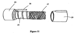
- the limb includes an elongate reinforcing member or spine 24 lying freely within conduit 25.
- Conduit 25 for example, is such as those described above.
- the second end of conduit end connector 23 has a recess 26 adapted to receive an elongate reinforcing spine or rod 24.
- the spine 24 runs the length of the conduit from the connector 23 at one end of the tube, down the inside of the conduit, and is secured in another end connector 49 at the other end of the conduit.
- the spine is substantially the same length as the conduit and follows a non-tortuous path between the connectors. Because the spine (between the connectors) is preferably slightly longer than the conduit, it will not follow a linear path, but rather will bend into a shallow wavy and/or spiral form.
Landscapes
- Engineering & Computer Science (AREA)
- Health & Medical Sciences (AREA)
- Mechanical Engineering (AREA)
- General Engineering & Computer Science (AREA)
- General Health & Medical Sciences (AREA)
- Pulmonology (AREA)
- Anesthesiology (AREA)
- Biomedical Technology (AREA)
- Heart & Thoracic Surgery (AREA)
- Hematology (AREA)
- Life Sciences & Earth Sciences (AREA)
- Animal Behavior & Ethology (AREA)
- Emergency Medicine (AREA)
- Public Health (AREA)
- Veterinary Medicine (AREA)
- Manufacturing & Machinery (AREA)
- Materials For Medical Uses (AREA)
- Respiratory Apparatuses And Protective Means (AREA)
- Rigid Pipes And Flexible Pipes (AREA)
- Finger-Pressure Massage (AREA)
- Orthopedics, Nursing, And Contraception (AREA)
- Telephone Function (AREA)
- Media Introduction/Drainage Providing Device (AREA)
- External Artificial Organs (AREA)
- Heterocyclic Carbon Compounds Containing A Hetero Ring Having Oxygen Or Sulfur (AREA)
Abstract
Description
an annular shoulder between said first end and said second end,
said second end extending along an axis and having a substantially circular cross section, and
said second end having at least one protrusion on an outer surface for interlocking engagement with a helical rib of a breathing conduit.
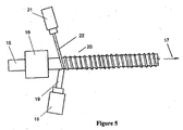
An example of forming apparatus suitable for manufacturing the double walled breathing tube product according to the embodiment described in Figure 2 is shown in Figure 3. The apparatus includes a former 1 preferably of a known type including a plurality of rotating rods arranged around a central support rod. The rods extend from and are rotated by a gearbox within a
Such variations may include:
Claims (24)
- A limb for a breathing circuit comprising:a very thin walled conduit (25) having a first end and a second end and a breathing gases pathway therebetween,a first connector (23) fixed to said first end of said conduit,a second connector (49) fixed to said second end of said conduit, characterised in that said limb further comprises,an elongate reinforcing member (24) lying freely within said very thin walled conduit along a non-tortuous path from one end of said conduit to the other end of said conduit, and connected with said first connector (23) and said second connector (49).
- A limb for a breathing circuit as claimed in claim 1, further characterised in that said elongate reinforcing member (24) has a cross sectional area, measured from the outer perimeter, less than 10% of the cross sectional area of the bore of said breathing conduit.
- A limb for a breathing circuit as claimed in claim 1 or claim 2, further characterised in that said elongate reinforcing member (24) is hollow, and said hollow elongate reinforcing member is blind terminated at each end by said first connector (23) and said second connector (49).
- A limb for a breathing circuit as claimed in claim 3, further characterised in that said hollow elongate reinforcing member (24) is too small to be a conduit for gases delivery to a patient, but large enough to be used as a pressure measurement or feedback conduit.
- A limb for a breathing circuit as claimed in claim 1 or claim 2, further characterised in that said elongate reinforcing member (24) has a solid, substantially circular cross section, and two ends.
- A limb for a breathing circuit as claimed in any one of claims 1 to 5, further characterised in that said elongate reinforcing member (24) includes a positive temperature coefficient heating element.
- A limb for a breathing circuit as claimed in any one of claims 1 to 5, further characterised in that said elongate reinforcing member (24) includes a resistance heating element.
- A limb for a breathing circuit as claimed in any one of claims 1 to 7, further characterised in that the length of said elongate reinforcing member (24) is between 100.5% and 105% of the length of said conduit.
- A limb for a breathing circuit as claimed in any one of claims 1 to 8, further characterised in that said connectors have a first end suitable for making connection with auxiliary equipment and a second end for making connection with a breathing conduit, and
an annular shoulder between said first end and said second end,
said second end extending along an axis and having a substantially circular cross section, and
said second end having at least one protrusion on an outer surface for interlocking engagement with a helical rib (35) of a breathing conduit. - A limb for a breathing circuit as claimed in claim 9, further characterised in that said protrusion is an external thread (28) having a pitch suitable for engagement with said helical rib (35) of a breathing conduit.
- A limb for a breathing circuit as claimed in claim 9 or claim 10, further characterised in that said shoulder portion has an annular recess (32) for receiving a securing collar (29) having an extrusion axis.
- A limb for a breathing circuit as claimed in any one of claims 9 to 11, further characterised in that said second end of said end connector has a recess (26) substantially parallel with said axis for receiving said elongate reinforcing member (24).
- A limb for a breathing circuit as claimed in claim 11, further characterised in that said securing collar (29) has a recess substantially parallel with said extrusion axis for receiving said elongate reinforcing member (24).
- A limb for a breathing circuit as claimed in any one of claims 1 to 13, further characterised in that said elongate reinforcing member (24) is resilient and does not plastically deform in use, under normal flexing and bending of said limb.
- A limb for a breathing circuit as claimed in any one of claims 1 to 14, further characterised in that said elongate reinforcing member (24) has a cross sectional area between 3 mm2 and 12.5 mm2.
- A limb for a breathing circuit as claimed in any one of claims 1 to 15, further characterised in that said elongate reinforcing member (24) has a minimum bending stiffness between 693 N.mm2 and 11096 N.mm2.
- A limb for a breathing circuit as claimed in any one of claims 1 to 16, characterised in that said limb further comprises:a braided sheath (27) surrounding said conduit and being fixed at and around one end to said first connector and at and around its other end to said second connector.
- A limb for a breathing circuit as claimed in claim 17, further characterised in that said sheath (27) is a braided tube braided from polyethylene terephthalate monofilaments.
- A method for manufacturing a limb for a breathing circuit comprising:providing a very thin walled breathing conduit (25) having a first end and a second end, characterised in that said method comprises the further steps of,locating an elongate reinforcing member (24) having a first and a second end, lying freely within said conduit, along a non-tortuous path from one end of said conduit to the other end of said conduit,fixing a first end connector (23) with a first end of said breathing conduit, and a first end of said elongate reinforcing member, andfixing a second end connector (49) with said second end of said conduit and said second end of said elongate reinforcing member.
- A method for manufacturing a limb for a breathing circuit as claimed in claim 19, characterised in that said method further comprises the steps of:locating a reinforcing mesh (27) having a first and a second end, over the outside of said breathing conduit,fixing a first end connector with a first end of said breathing conduit, and a first end of said reinforcing mesh, andfixing a second end connector with said second end of said conduit and said second end of said reinforcing mesh.
- A method for manufacturing a limb for a breathing circuit comprising:providing a very thin walled breathing conduit (25) having a first end and a second end, characterised in that said method further comprises the steps of,locating a reinforcing mesh (27) having a first and a second end, over the outside of said breathing conduit,fixing a first end connector with a first end of said breathing conduit, and a first end of said reinforcing mesh, and
fixing a second end connector with said second end of said conduit and said second end of said reinforcing mesh. - A limb for a breathing circuit comprising:a very thin walled conduit (25) having a first end and a second end,a first connector fixed to said first end of said conduit,a second connector fixed to a second end of said conduit, characterised in that said limb further comprises,a braided sheath (27) surrounding said conduit and being fixed at and around one end to said first connector and at and around its other end to said second connector.
- A limb for a breathing circuit as claimed in claim 22, further characterised in that said sheath (27) is a braided tube braided from polyethylene terephthalate monofilaments.
- A limb for a breathing circuit as claimed in claim 22 or claim 23, further characterised in that said conduit includes a helical reinforcing bead (35).
Applications Claiming Priority (2)
| Application Number | Priority Date | Filing Date | Title |
|---|---|---|---|
| NZ52127402 | 2002-09-09 | ||
| NZ52127402 | 2002-09-09 |
Publications (3)
| Publication Number | Publication Date |
|---|---|
| EP1396276A2 true EP1396276A2 (en) | 2004-03-10 |
| EP1396276A3 EP1396276A3 (en) | 2004-05-19 |
| EP1396276B1 EP1396276B1 (en) | 2005-11-16 |
Family
ID=31713220
Family Applications (1)
| Application Number | Title | Priority Date | Filing Date |
|---|---|---|---|
| EP03020200A Expired - Lifetime EP1396276B1 (en) | 2002-09-09 | 2003-09-05 | Limb for breathing circuit |
Country Status (10)
| Country | Link |
|---|---|
| US (6) | US7469719B2 (en) |
| EP (1) | EP1396276B1 (en) |
| JP (1) | JP4317416B2 (en) |
| AT (1) | ATE309836T1 (en) |
| AU (1) | AU2003244171B2 (en) |
| BR (1) | BRPI0303478B8 (en) |
| CA (1) | CA2439765C (en) |
| DE (1) | DE60302302T2 (en) |
| SG (1) | SG108937A1 (en) |
| TW (1) | TWI237574B (en) |
Cited By (7)
| Publication number | Priority date | Publication date | Assignee | Title |
|---|---|---|---|---|
| DE102009005643A1 (en) * | 2009-01-22 | 2010-08-12 | Siemens Aktiengesellschaft | Device for increasing the bending stiffness of hoses |
| NL2008232C2 (en) * | 2012-02-03 | 2013-08-06 | Bosch Gmbh Robert | Combination of a heating device, a connector, and a gas meter, as well as a method for measuring a property of a gas. |
| US8726901B2 (en) | 2005-10-20 | 2014-05-20 | Intersurgical Ag | Ventilation tubes |
| US8905082B2 (en) | 2002-09-09 | 2014-12-09 | Fisher & Paykel Healthcare Limited | Limb for breathing circuit |
| CN105135092A (en) * | 2015-09-02 | 2015-12-09 | 潘小雄 | Inner-fin-reinforced polyethylene PE spiral corrugated pipe |
| WO2020094741A1 (en) | 2018-11-08 | 2020-05-14 | Plastiflex Group | Moisture permeable conduit for a breathing circuit |
| US12280214B2 (en) | 2000-06-21 | 2025-04-22 | Fisher & Paykel Healthcare Limited | Conduit with heating element |
Families Citing this family (86)
| Publication number | Priority date | Publication date | Assignee | Title |
|---|---|---|---|---|
| BR0102116B1 (en) | 2000-05-10 | 2010-09-21 | component for a breathing circuit member. | |
| US7291240B2 (en) * | 2002-09-09 | 2007-11-06 | Fisher & Paykel Healthcare Limited | Method of forming a conduit using a wound sacrificial layer |
| AU2004202274B2 (en) | 2003-05-30 | 2006-10-26 | Fisher & Paykel Healthcare Limited | Breathing Assistance Apparatus |
| AU2004203870B2 (en) | 2003-09-17 | 2011-03-03 | Fisher & Paykel Healthcare Limited | Breathable Respiratory Mask |
| US7766050B2 (en) * | 2003-11-28 | 2010-08-03 | Fisher & Paykel Healthcare Limited | Conduit and method of forming |
| US20060004393A1 (en) * | 2004-05-13 | 2006-01-05 | Amarant Paul D | Percutaneous anastomosis connection system |
| US7393181B2 (en) | 2004-09-17 | 2008-07-01 | The Penn State Research Foundation | Expandable impeller pump |
| US20080203726A1 (en) * | 2005-07-28 | 2008-08-28 | Breeser David L | Data Communication System Embedded In A Fluid Dispensing Line With Limited Travel Swivel |
| US9486274B2 (en) | 2005-09-07 | 2016-11-08 | Ulthera, Inc. | Dissection handpiece and method for reducing the appearance of cellulite |
| US9011473B2 (en) | 2005-09-07 | 2015-04-21 | Ulthera, Inc. | Dissection handpiece and method for reducing the appearance of cellulite |
| US9358033B2 (en) | 2005-09-07 | 2016-06-07 | Ulthera, Inc. | Fluid-jet dissection system and method for reducing the appearance of cellulite |
| US8518069B2 (en) | 2005-09-07 | 2013-08-27 | Cabochon Aesthetics, Inc. | Dissection handpiece and method for reducing the appearance of cellulite |
| US10548659B2 (en) | 2006-01-17 | 2020-02-04 | Ulthera, Inc. | High pressure pre-burst for improved fluid delivery |
| US7885793B2 (en) | 2007-05-22 | 2011-02-08 | International Business Machines Corporation | Method and system for developing a conceptual model to facilitate generating a business-aligned information technology solution |
| US9248317B2 (en) | 2005-12-02 | 2016-02-02 | Ulthera, Inc. | Devices and methods for selectively lysing cells |
| WO2007109837A1 (en) | 2006-03-24 | 2007-10-04 | Resmed Ltd | Air delivery conduit |
| EP2079505B1 (en) * | 2006-11-08 | 2020-07-15 | ResMed Pty Ltd | Conduit for use in a respiratory apparatus |
| US8944056B2 (en) | 2007-02-09 | 2015-02-03 | Resmed Limited | Humidification arrangement for a respiratory apparatus |
| US8439940B2 (en) | 2010-12-22 | 2013-05-14 | Cabochon Aesthetics, Inc. | Dissection handpiece with aspiration means for reducing the appearance of cellulite |
| US9505164B2 (en) | 2009-12-30 | 2016-11-29 | Schauenburg Technology Se | Tapered helically reinforced hose and its manufacture |
| DE102008022663B4 (en) * | 2008-05-07 | 2012-10-31 | Schauenburg Hose Technology Gmbh | Stretch hose |
| US9903371B2 (en) | 2008-09-17 | 2018-02-27 | Resmed Limited | Cuff for air delivery conduit |
| US9964238B2 (en) | 2009-01-15 | 2018-05-08 | Globalmed, Inc. | Stretch hose and hose production method |
| US11096708B2 (en) | 2009-08-07 | 2021-08-24 | Ulthera, Inc. | Devices and methods for performing subcutaneous surgery |
| US9358064B2 (en) | 2009-08-07 | 2016-06-07 | Ulthera, Inc. | Handpiece and methods for performing subcutaneous surgery |
| USD742508S1 (en) | 2013-07-12 | 2015-11-03 | Resmed Limited | Air delivery tube with cuff |
| CN105343971B (en) | 2009-12-22 | 2018-03-30 | 费雪派克医疗保健有限公司 | Component for medical loop |
| CN101852316A (en) * | 2010-06-07 | 2010-10-06 | 韩路平 | Polyethylene-wound structure wall tube and pipe without frame pipe and production method thereof |
| CN101907207A (en) * | 2010-07-06 | 2010-12-08 | 戴爱清 | Internal rib reinforcing outer ripple type plastic twining structured wall pipe and manufacturing method thereof |
| GB2531985B (en) | 2010-10-18 | 2016-06-22 | Fisher & Paykel Healthcare Ltd | A nasal cannula, conduit and securement system |
| DE102010051550A1 (en) * | 2010-11-18 | 2012-05-24 | Voss Automotive Gmbh | Assembled electrically heatable media line and method for producing such a media line |
| CN103442763B (en) | 2011-03-15 | 2016-11-09 | 瑞思迈有限公司 | air delivery duct |
| EP2704785B1 (en) * | 2011-05-06 | 2019-07-10 | Fisher & Paykel Healthcare Limited | Component for medical circuit |
| GB2557116B (en) * | 2011-06-03 | 2018-10-03 | Fisher & Paykel Healthcare Ltd | Medical tubes and methods of manufacture |
| WO2013002655A2 (en) * | 2011-06-28 | 2013-01-03 | Fisher & Paykel Healthcare Limited | Improved medical tubing |
| US20130061975A1 (en) * | 2011-09-14 | 2013-03-14 | David Wayne Leadingham | Aircraft ground support hose assembly |
| US20130118626A1 (en) * | 2011-11-15 | 2013-05-16 | Illinois Tool Works Inc. | Method of attaching a stiffening wire inside a flexible hose assembly |
| CA3176668A1 (en) | 2012-03-15 | 2013-09-19 | Fisher & Paykel Healthcare Limited | Respiratory gas humidification system |
| WO2013156914A2 (en) * | 2012-04-17 | 2013-10-24 | Koninklijke Philips N.V. | Gas delivery conduit for a respiratory therapy system |
| US9974921B2 (en) | 2012-04-27 | 2018-05-22 | Fisher & Paykel Healthcare Limited | Usability features for respiratory humidification system |
| DE102013008159A1 (en) | 2012-05-14 | 2013-11-14 | Thoratec Corporation | Sheath system for catheter pump |
| GB2504176A (en) | 2012-05-14 | 2014-01-22 | Thoratec Corp | Collapsible impeller for catheter pump |
| AU2013281354B2 (en) | 2012-06-25 | 2018-03-22 | Fisher & Paykel Healthcare Limited | Medical components with microstructures for humidification and condensate management |
| US10589050B2 (en) | 2012-11-14 | 2020-03-17 | Fisher & Paykel Healthcare Limited | Zone heating for respiratory circuits |
| EP3708212B1 (en) * | 2012-12-04 | 2024-05-22 | Fisher & Paykel Healthcare Limited | A respiratory conduit |
| EP2968830B1 (en) | 2013-03-14 | 2019-03-06 | Fisher & Paykel Healthcare Limited | Humidification chamber with microstructured surface |
| GB2534496B (en) | 2013-09-13 | 2020-04-01 | Fisher & Paykel Healthcare Ltd | A cartridge for a respiratory humidifier |
| WO2015060731A1 (en) | 2013-10-24 | 2015-04-30 | Fisher & Paykel Healthcare Limited | Delivery of respiratory gases |
| CN110947069A (en) | 2013-12-20 | 2020-04-03 | 费雪派克医疗保健有限公司 | Humidification system connection |
| WO2015119515A1 (en) | 2014-02-07 | 2015-08-13 | Fisher & Paykel Healthcare Limited | Respiratory humidification system |
| US10751498B2 (en) | 2014-03-17 | 2020-08-25 | Fisher & Paykel Healthcare Limited | Medical tubes for respiratory systems |
| USD762843S1 (en) | 2014-03-18 | 2016-08-02 | Resmed Limited | Air delivery tube |
| WO2015160980A1 (en) | 2014-04-15 | 2015-10-22 | Thoratec Corporation | Heart pump providing adjustable out flow |
| CN112370630A (en) | 2014-06-03 | 2021-02-19 | 费雪派克医疗保健有限公司 | Flow mixer for respiratory therapy system |
| EP4706723A3 (en) * | 2014-07-07 | 2026-05-06 | Fisher & Paykel Healthcare Limited | Medical tubes and connectors for gases delivery systems |
| EP4186548A1 (en) | 2015-04-02 | 2023-05-31 | Hill-Rom Services PTE. LTD. | Mask leakage detection for a respiratory device |
| WO2017037660A1 (en) * | 2015-09-04 | 2017-03-09 | Fisher & Paykel Healthcare Limited | Connectors for conduits |
| SG10202002134QA (en) | 2015-09-09 | 2020-05-28 | Fisher & Paykel Healthcare Ltd | Zone heating for respiratory circuits |
| USD807995S1 (en) | 2015-09-22 | 2018-01-16 | Fisher & Paykel Healthcare Limited | Circuit kit for a humidifier |
| USD841147S1 (en) | 2015-09-30 | 2019-02-19 | Fisher & Paykel Healthcare Limited | Circuit kit for a humidifier |
| US11504492B2 (en) * | 2015-10-08 | 2022-11-22 | ResMed Pty Ltd | Air conduit for a respiratory device |
| USD805630S1 (en) | 2016-02-02 | 2017-12-19 | Resmed Limited | Air delivery tube |
| EP4223338B1 (en) | 2016-06-07 | 2025-08-27 | Fisher & Paykel Healthcare Limited | Breathing circuit components for respiratory apparatus |
| PL3487571T3 (en) | 2016-07-21 | 2024-07-29 | Fisher & Paykel Healthcare Limited | Medical tubes for breathing circuit |
| USD841148S1 (en) | 2016-07-21 | 2019-02-19 | Fisher & Paykel Healthcare Limited | Breathing tube |
| WO2018106126A1 (en) | 2016-12-07 | 2018-06-14 | Fisher And Paykel Healthcare Limited | Sensing arrangements for medical devices |
| EP3544662B1 (en) | 2016-12-22 | 2024-11-27 | Fisher & Paykel Healthcare Limited | Medical tubes and methods of manufacture |
| EP3597250B1 (en) | 2017-01-30 | 2023-02-22 | GlobalMed, Inc. | Heated respiratory hose assembly |
| ES2979252T3 (en) * | 2017-05-26 | 2024-09-25 | Fisher & Paykel Healthcare Ltd | Flexible and hybrid neonatal medical tubes |
| USD878549S1 (en) | 2017-11-21 | 2020-03-17 | Fisher & Paykel Healthcare Limited | Connector for nasal cannula assembly |
| USD848614S1 (en) | 2017-11-21 | 2019-05-14 | Fisher & Paykel Healthcare Limited | Pad for nasal cannula assembly |
| USD849242S1 (en) | 2017-11-21 | 2019-05-21 | Fisher & Paykel Healthcare Limited | Nasal cannula assembly |
| USD849243S1 (en) | 2017-11-21 | 2019-05-21 | Fisher & Paykel Healthcare Limited | Nasal cannula |
| JP7661041B2 (en) | 2018-01-24 | 2025-04-14 | フィッシャー アンド ペイケル ヘルスケア リミテッド | Medical tubing for breathing circuits |
| EP3836998A4 (en) | 2018-08-13 | 2022-05-04 | Fisher & Paykel Healthcare Limited | APPARATUS INTENDED FOR USE IN A RESPIRATORY SUPPORT SYSTEM |
| USD958968S1 (en) | 2018-11-28 | 2022-07-26 | Fisher & Paykel Healthcare Limited | Breathing tube with mesh |
| WO2020165760A1 (en) * | 2019-02-13 | 2020-08-20 | ResMed Pty Ltd | Textile tube for a therapy device |
| USD937411S1 (en) | 2019-08-30 | 2021-11-30 | Fisher & Paykel Healthcare Limited | Unit end connector |
| CN112917890B (en) * | 2021-01-25 | 2022-07-22 | 宜宾天亿新材料科技有限公司 | A kind of PVC-O pipe fittings all-covering film method |
| US20220379065A1 (en) * | 2021-05-31 | 2022-12-01 | Matthew H. Quintana | No kink oxygen hose |
| CA3238208A1 (en) * | 2021-11-12 | 2023-05-19 | Safeback As | A survival device for feeding a steady supply of breathable air into an environment |
| CN114083786B (en) * | 2021-11-19 | 2024-08-09 | 上海合辉电子元件有限公司 | Auxiliary shaping assembly of stretching die |
| CN220757791U (en) * | 2022-02-04 | 2024-04-12 | 费雪派克医疗保健有限公司 | Connector with a plurality of connectors |
| CN114683057B (en) * | 2022-04-15 | 2023-03-14 | 中国空间技术研究院 | A thin-walled bar manufacturing equipment and method |
| US12663103B2 (en) * | 2022-09-23 | 2026-06-23 | Luohe Letone Hydraulics Technology Co., Ltd. | Hose, hose assembly, and manufacture method |
| CN119773189A (en) * | 2025-03-07 | 2025-04-08 | 广东毅达医疗科技股份有限公司 | A production device and method for a breathing tube |
Family Cites Families (376)
| Publication number | Priority date | Publication date | Assignee | Title |
|---|---|---|---|---|
| DE28036C (en) | 1884-02-12 | 1884-07-23 | J. WOLFF in Grofs-Gerau, Gr. Hessen | Outdoor breathers |
| US928237A (en) | 1908-12-16 | 1909-07-20 | John P Baird | Hose-coupling. |
| GB191509683A (en) | 1915-12-22 | 1916-09-21 | Edgar George Payne | Improvements in, or connected with, Ambulances, Stretchers, Litters, and the like. |
| US1361206A (en) * | 1918-11-11 | 1920-12-07 | Williamson & Co R | Flexible gas-tubing |
| US1558804A (en) | 1918-11-20 | 1925-10-27 | Eugene L Greenewald | Method of and apparatus for making reenforced products |
| US1406578A (en) | 1921-07-07 | 1922-02-14 | Thomas E Murray | Method of molding pipes of plastic material |
| US2250430A (en) | 1935-06-08 | 1941-07-22 | Sylvania Ind Corp | Process and apparatus for forming tubing |
| GB587163A (en) | 1944-02-04 | 1947-04-16 | Wingfoot Corp | Improvements relating to tubes or packages and methods of making the same |
| US2748830A (en) | 1953-01-14 | 1956-06-05 | American Fixture Inc | Method and apparatus for making spiral wound synthetic piping and tubing |
| US2868199A (en) | 1955-05-20 | 1959-01-13 | Charles H Hudson | Cannula |
| US2917568A (en) * | 1956-10-25 | 1959-12-15 | Dayton Rubber Company | Oxygen delivery tube |
| US2943644A (en) * | 1957-02-01 | 1960-07-05 | Compoflox Company Ltd | Flexible hose |
| GB863105A (en) | 1957-10-31 | 1961-03-15 | Titeflex Inc | Re-inforced flexible plastic hose pipes and method of making same |
| GB863106A (en) | 1957-10-31 | 1961-03-15 | Titeflex Inc | Method of making synthetic plastic hose pipes |
| US3073353A (en) * | 1958-06-25 | 1963-01-15 | Porter Co Inc H K | Abrasion-resistant ventilating jacket for jet engine starter hoses |
| GB859613A (en) * | 1958-08-27 | 1961-01-25 | Superflexit | Improvements in or relating to end fittings for tubing |
| GB975819A (en) | 1960-04-01 | |||
| DE123476C (en) | 1960-09-19 | |||
| US3294609A (en) | 1960-10-17 | 1966-12-27 | Albin M Hancik | Method of making a laminated plastic tube |
| US3188117A (en) * | 1961-03-03 | 1965-06-08 | Resistoflex Corp | Hose coupling having a continuous outer sheath |
| US3271221A (en) | 1961-06-22 | 1966-09-06 | Cornell Dubilier Electric | Method of making an electrical condenser |
| US3163707A (en) * | 1962-12-27 | 1964-12-29 | Ralph E Darling | Non-stretch flexible tube with conductors therein |
| US3303105A (en) | 1963-03-25 | 1967-02-07 | Gen Electric | Diffusion of water vapor through slicone rubber |
| GB1091013A (en) * | 1963-05-02 | 1967-11-15 | Plessey Uk Ltd | Improvements in or relating to the attachment of braid-covered corrugated tubing to solid end sleeves |
| US3376181A (en) | 1963-07-31 | 1968-04-02 | Continental Can Co | Method and apparatus for blowing plastic liner in continuously formed tubes having longitudinal seam |
| US3245206A (en) | 1963-08-02 | 1966-04-12 | Engelhard Ind Inc | Diffusion purification apparatus |
| US3279333A (en) | 1963-11-27 | 1966-10-18 | Resinite Corp | Method of making a spirallywound tube |
| US3292346A (en) | 1964-03-06 | 1966-12-20 | Renard P Adams | Gas drying apparatus |
| US3367850A (en) | 1964-12-07 | 1968-02-06 | Exxon Research Engineering Co | Method and apparatus for determining moisture content of hydrocarbon fluids |
| US3349806A (en) * | 1964-12-07 | 1967-10-31 | Fred T Roberts & Company | Reinforced hose construction and method of making the same |
| US3307330A (en) | 1965-04-30 | 1967-03-07 | Du Pont | Diffusion process and apparatus |
| US3434471A (en) | 1966-04-06 | 1969-03-25 | Smithkline Corp | Therapeutic intermittent positive pressure respirator |
| US3394954A (en) | 1966-05-06 | 1968-07-30 | Sarns Inc | Tube coupling for medical appliances |
| US3513844A (en) | 1968-04-30 | 1970-05-26 | Metro Hospital Supply Co Inc | Adjustable nonrestrictive nasal cannula |
| US3578777A (en) | 1969-06-11 | 1971-05-18 | Koppy Tool Corp | Corrugated tubing |
| US3616796A (en) | 1969-06-30 | 1971-11-02 | Richard Robert Jackson | Humidified respiratory tube and method |
| US3700513A (en) | 1969-09-18 | 1972-10-24 | Spiess C F & Sohn | Method of making tube |
| US3639970A (en) | 1969-10-02 | 1972-02-08 | Phillips Petroleum Co | Method and apparatus for forming plastic-lined metal conduit |
| GB1381781A (en) | 1972-02-01 | 1975-01-29 | Barratt W C | Manufacture of articles of flowable hardenable material |
| US3857415A (en) * | 1970-09-15 | 1974-12-31 | Everflex Prod Inc | Reinforced convoluted tubing of polytetrafluoroethylene |
| US3677329A (en) | 1970-11-16 | 1972-07-18 | Trw Inc | Annular heat pipe |
| US3693856A (en) | 1971-01-04 | 1972-09-26 | Burroughs Corp | Releasable clamp for a driving member of a strip-like medium |
| US3829340A (en) | 1971-03-17 | 1974-08-13 | Western Electric Co | Methods of making a tubular member having a sealed longitudinal seam |
| US3682171A (en) | 1971-03-31 | 1972-08-08 | Baxter Laboratories Inc | Nasal cannula |
| US3739815A (en) | 1971-04-30 | 1973-06-19 | Wiremold Co | Flexible collapsible tubing |
| US3754552A (en) | 1971-06-08 | 1973-08-28 | Sandoz Ag | Flexible nasal cannula |
| US3735558A (en) | 1971-06-29 | 1973-05-29 | Perma Pure Process Inc | Process for separating fluids and apparatus |
| US3891556A (en) | 1971-11-15 | 1975-06-24 | Oxy Metal Ind Intra Inc | Multi-layer braided tubular membrane reinforcement |
| US3735559A (en) | 1972-02-02 | 1973-05-29 | Gen Electric | Sulfonated polyxylylene oxide as a permselective membrane for water vapor transport |
| US3856051A (en) | 1972-02-28 | 1974-12-24 | J Bain | Flexible tube device |
| DE2218561C3 (en) | 1972-04-17 | 1978-04-27 | Uniroyal Ag, 5100 Aachen | Pick-up mandrel for devices for cutting rings from hoses or pipes made of rubber, plastic or similar material, which have an inextensible insert |
| US3803810A (en) | 1972-05-01 | 1974-04-16 | Pall Corp | Liquid-gas separator and filter |
| FR2185178A5 (en) * | 1972-05-19 | 1973-12-28 | Rhone Poulenc Sa | |
| US3910808A (en) | 1972-08-30 | 1975-10-07 | Steward Plastics | Apparatus for making helically wound plastic tubing |
| DE2321553C2 (en) | 1972-08-30 | 1983-10-20 | Steward Plastics, Inc., Santa Ana, Calif. | Device for producing a helically wound flexible pipe |
| US3871373A (en) | 1972-10-30 | 1975-03-18 | Richard R Jackson | Humidifying gas |
| US3912795A (en) | 1972-10-30 | 1975-10-14 | Richard R Jackson | Humidifying gas |
| DE2413132A1 (en) | 1973-04-11 | 1974-10-31 | Atco Rubber Prod Inc | MOVABLE PIPE CONSTRUCTION AND METHOD OF MANUFACTURING IT |
| US3895630A (en) | 1973-06-04 | 1975-07-22 | Del Mar Eng Lab | Respiratory gas analyzer including a carbon dioxide and respiratory quotient computer |
| US3866632A (en) | 1973-07-02 | 1975-02-18 | Gates Rubber Co | Reinforced hose and method |
| US3945867A (en) * | 1973-11-05 | 1976-03-23 | William C. Heller, Jr. | Plastic hose making method |
| US3889717A (en) | 1973-12-14 | 1975-06-17 | Deere & Co | Reinforced flexible tube |
| US4007737A (en) | 1974-01-28 | 1977-02-15 | Paluch Bernard R | Anesthesia breathing system |
| CH581474A5 (en) | 1974-06-27 | 1976-11-15 | Draegerwerk Ag | |
| US4035211A (en) | 1974-07-02 | 1977-07-12 | Western Electric Company, Inc. | Forming sealed seams in moisture barriers for cable |
| US3963856A (en) | 1974-11-25 | 1976-06-15 | Steward Plastics, Inc. | Flexible, corrugated, plastic tubing having conductive helical bead |
| US4000759A (en) * | 1974-12-11 | 1977-01-04 | The Gates Rubber Company | Hose |
| DE2529050C2 (en) * | 1975-06-30 | 1983-01-05 | Drägerwerk AG, 2400 Lübeck | Moisture exchanger in devices for breathing and anesthesia |
| DE2711236C2 (en) | 1976-05-14 | 1982-09-23 | Shiro Osaka Ibaragi Kanao | Method and device for the continuous production of a pipe |
| US4083245A (en) | 1977-03-21 | 1978-04-11 | Research Development Corporation | Variable orifice gas flow sensing head |
| US4086035A (en) | 1977-03-18 | 1978-04-25 | Klaeger Jr Joseph Hart | Bailer pumps for oil wells |
| DE2719851C3 (en) * | 1977-05-04 | 1982-01-28 | Gummi-Roller Gmbh & Co, 6236 Eschborn | Monotube with lead-out electrically conductive wires and method for leading the wires out of the monotube |
| US4327775A (en) | 1977-05-09 | 1982-05-04 | The Gates Rubber Company | Formable hose with a reformable insert |
| US4130617A (en) | 1977-12-30 | 1978-12-19 | Airco, Inc. | Method of making endotracheal tube cuffs |
| US4204562A (en) | 1978-04-27 | 1980-05-27 | Kelly Walter F | Two-ply duct core |
| US4194041A (en) | 1978-06-29 | 1980-03-18 | W. L. Gore & Associates, Inc. | Waterproof laminate |
| US4207457A (en) | 1978-06-29 | 1980-06-10 | The Kanthal Corporation | Porcupine wire coil electric resistance fluid heater |
| US4262704A (en) | 1978-08-30 | 1981-04-21 | Caterpillar Tractor Co. | High pressure reinforced hydraulic hose |
| US4180103A (en) * | 1978-09-07 | 1979-12-25 | Western Geophysical Co. Of America | Termination fixture for a marine seismic streamer cable |
| US4216769A (en) | 1978-09-29 | 1980-08-12 | Grimes Jerry L | Bi-flow nasal cup |
| US4265239A (en) | 1978-11-27 | 1981-05-05 | Fischer Jr Charles M | Gas scavenging exhaust system |
| US4265235A (en) | 1979-05-11 | 1981-05-05 | Fukunaga Atsuo F | Anesthetic system |
| DE2929584A1 (en) | 1979-07-21 | 1981-02-05 | Draegerwerk Ag | MOISTURE EXCHANGER IN BREATHING DEVICES |
| JPS5689531A (en) | 1979-12-20 | 1981-07-20 | Toyo Chem Co Ltd | Corrugated pipe |
| US4367735A (en) | 1979-12-31 | 1983-01-11 | Novametrix Medical Systems, Inc. | Nasal cannula |
| US4456034A (en) | 1980-02-19 | 1984-06-26 | Bixby Guy T | Formable hose |
| US4295496A (en) * | 1980-02-19 | 1981-10-20 | The Gates Rubber Company | Hose with internal insert member |
| JPS601888B2 (en) | 1980-02-25 | 1985-01-18 | 日東電工株式会社 | Manufacturing method of polyimide tubes |
| US4304266A (en) | 1980-03-24 | 1981-12-08 | Automation Industries, Inc. | Smooth bore flexible hose |
| US4406514A (en) | 1980-03-26 | 1983-09-27 | Harris Corporation | Single fiber connector for pluggable card or module optical interconnections |
| US4415389A (en) * | 1980-05-05 | 1983-11-15 | Dayco Corporation | Method of making a hose construction |
| US4403514A (en) | 1980-05-20 | 1983-09-13 | Critikon, Inc. | Pneumotachograph with pitot-like tubes |
| US4337800A (en) | 1980-07-07 | 1982-07-06 | Steward Plastics, Inc. | Two piece extruded hose |
| US4327718A (en) | 1980-09-18 | 1982-05-04 | Becton, Dickinson And Company | Continuously draining trap for removal of condensate from a patient breathing circuit |
| US4653542A (en) | 1980-10-02 | 1987-03-31 | The Kendall Company | Medical tubing and connector |
| US4336798A (en) | 1980-10-06 | 1982-06-29 | Anthony V. Beran | Medical corrugated respiratory tube |
| US4462397A (en) | 1981-04-03 | 1984-07-31 | Terumo Corporation | Breathing circuit |
| US4463755A (en) | 1981-05-18 | 1984-08-07 | Terumo Corporation | Breathing circuit |
| SE428345C (en) | 1981-12-23 | 1989-04-17 | Gambro Engstrom Ab | METHOD AND MEASUREMENT PROCEDURE MEASURING THE CONCENTRATION OF ONE OR MORE GIVEN COMPONENTS IN ONE OF A PATIENT IN AND OR EXHAUSTED BREATHING GAS |
| US4420016A (en) | 1982-01-07 | 1983-12-13 | Nichols Ralph A | Kink-preventing spine for aquarium air hoses |
| US4406283A (en) | 1982-02-04 | 1983-09-27 | Phillip Bir | Oxygen cannulae for continuous administration of oxygen, and its associated mounting structure and method for mounting same onto the head of a patient |
| US4417574A (en) | 1982-05-03 | 1983-11-29 | Sherwood Medical Company | Liquid drain for patient breathing apparatus |
| FR2527246A1 (en) * | 1982-05-21 | 1983-11-25 | Freyssinet Int Stup | IMPROVEMENTS IN PRE-STRESS CONDUITS AND THEIR MANUFACTURING METHODS |
| US4488921A (en) | 1982-09-23 | 1984-12-18 | Durodyne, Inc. | Method for fabricating long length hose utilizing an internal moving mandrel |
| CA1191439A (en) | 1982-12-02 | 1985-08-06 | Cornelius M.F. Vrouenraets | Flexible layered product |
| GB2139110B (en) | 1982-12-27 | 1987-05-20 | Gen Electric | Water vapor exchange system |
| JPS59119304U (en) | 1983-01-29 | 1984-08-11 | 株式会社エルマ | Dissolved gas deaerator in liquid |
| US4517404A (en) * | 1983-02-02 | 1985-05-14 | Dayco Corporation | Multiple fluid conveying hose assembly and method of making same |
| US4682010A (en) | 1983-03-07 | 1987-07-21 | Safeway Products, Inc. | In-line electric heater for an aerosol delivery system |
| US4490575A (en) | 1983-05-26 | 1984-12-25 | Automation Industries, Inc. | Flexible hose with external sheathed electrical conductor |
| US4597594A (en) | 1983-09-09 | 1986-07-01 | Chris Kaye Plastics Corp. | Hose connector |
| US4592351A (en) | 1983-12-05 | 1986-06-03 | Smith Norma W | Cannula holder |
| US4580816A (en) | 1984-01-25 | 1986-04-08 | E. R. Squibb & Sons, Inc. | Quick disconnect tube coupling |
| FR2564733B1 (en) | 1984-05-22 | 1987-05-29 | Centre Nat Rech Scient | PORTABLE APPARATUS FOR COMBATING HYPOTHERMIA IN MAN, BY INHALING HOT AND HUMIDIFIED AIR |
| DE3421364A1 (en) | 1984-06-08 | 1985-12-12 | Bayer Ag, 5090 Leverkusen | METHOD AND DEVICE FOR THE CONTINUOUS PRODUCTION OF LONELY HOLLOW BODIES, ESPECIALLY HOSES, TUBES OR INTERNAL LINERS FOR SUCH, FROM A LIQUID MATERIAL, LIKE REACTION MIXTURE OR MELT |
| US4773410A (en) | 1984-10-09 | 1988-09-27 | Transpirator Technologies, Inc. | Method and apparatus for the treatment of the respiratory track with vapor-phase water |
| JPH0310464Y2 (en) | 1984-10-22 | 1991-03-14 | ||
| US4621632A (en) | 1984-11-01 | 1986-11-11 | Bear Medical Systems, Inc. | Humidifier system |
| US4597596A (en) | 1984-11-07 | 1986-07-01 | Heat Transfer Technology Limited | Cylinder end seal |
| SU1342514A1 (en) | 1984-11-26 | 1987-10-07 | Всесоюзный научно-исследовательский институт горноспасательного дела | Moisture-heat-exchanger of respiratory system based on chemically bound oxygen |
| EP0210271B1 (en) | 1985-02-04 | 1990-05-09 | Witzenmann GmbH Metallschlauch-Fabrik Pforzheim | Flexible corrugated hose with ring-shaped parallel waves with axial support |
| DE3650465T2 (en) | 1985-02-09 | 1996-09-12 | Asahi Chemical Ind | Permeable polymer membrane for gas drying |
| GB2173274B (en) | 1985-04-04 | 1989-02-01 | Boc Group Plc | Improvements in inhalation apparatus |
| AU581986B2 (en) | 1985-05-22 | 1989-03-09 | Fisher & Paykel Healthcare Limited | Improvements in or relating to methods of and/or apparatus for humidifying gases |
| US4722334A (en) | 1985-07-16 | 1988-02-02 | Transpirator Technologies, Inc. | Method and apparatus for pulmonary and cardiovascular conditioning of racehorses and competition animals |
| US4669508A (en) * | 1985-10-31 | 1987-06-02 | The Gates Rubber Company | Formable and curve shape retentive hose |
| US4698890A (en) | 1985-10-31 | 1987-10-13 | The Gates Rubber Company | Method for making a formable and curve shape retentive hose |
| GB8528966D0 (en) * | 1985-11-25 | 1986-01-02 | Raychem Ltd | Wrap-around fabric articles |
| US4698196A (en) | 1985-12-24 | 1987-10-06 | Xerox Corporation | Method and apparatus for extruding creaseless thin walled tubes |
| US4854416A (en) * | 1986-06-09 | 1989-08-08 | Titeflex Corporation | Tuned self-damping convoluted conduit |
| JPS62236724A (en) | 1986-04-08 | 1987-10-16 | Taigaasu Polymer Kk | Manufacture of flexible pipe |
| US4715915A (en) | 1986-06-19 | 1987-12-29 | Carlisle Corporation | Longitudinal seam and method of forming |
| US4705543A (en) | 1986-09-19 | 1987-11-10 | Perma Pure Products, Inc. | Fluid drying tube |
| US4808201A (en) | 1986-09-19 | 1989-02-28 | Perma Pure Products, Inc. | Connector construction for fluid drying tube |
| US5623922A (en) * | 1986-09-23 | 1997-04-29 | Smith; Charles A. | Insulated breathing tube |
| US5735266A (en) * | 1986-09-23 | 1998-04-07 | Smith; Charles A. | Insulated conditioned respiratory air transport tube |
| US5377670A (en) * | 1986-09-23 | 1995-01-03 | Smith; Charles A. | Insulated breathing tube |
| US4753233A (en) | 1987-02-10 | 1988-06-28 | Advantage Medical | Nasal cannula |
| SE459155B (en) | 1987-04-14 | 1989-06-12 | Siemens Elema Ab | PROCEDURE AND PROCEDURE FOR THE APPLICATION OF ANESTHESIA |
| JPS63272530A (en) | 1987-04-30 | 1988-11-10 | Dainippon Plastics Co Ltd | Manufacture of corrugated tube |
| FI76488C (en) | 1987-05-05 | 1988-11-10 | Instrumentarium Oy | ROERVATTENAVSKILJARE TILL EN GASANALYSATOR. |
| US4874925A (en) * | 1987-06-01 | 1989-10-17 | Dickenson Wilk A | Electrically heated hose assembly for conveying electrically conductive liquids |
| US5061258A (en) | 1987-08-07 | 1991-10-29 | Martz Joel D | Vapor permeable dressing with releasable medication |
| US5160511A (en) | 1987-09-10 | 1992-11-03 | Hewlett-Packard Company | Water-vapour permeable material |
| NL8702422A (en) | 1987-10-12 | 1989-05-01 | Akzo Nv | ABSORBING HYGIENIC PRODUCT. |
| US4838258A (en) * | 1987-10-26 | 1989-06-13 | Gibeck-Dryden Corporation | Gas sampling lumen for breathing system |
| JP2584257B2 (en) * | 1987-11-18 | 1997-02-26 | 横浜ゴム株式会社 | Flexible hose |
| JPH01194927A (en) | 1988-01-27 | 1989-08-04 | Japan Gore Tex Inc | Steam permselective membrane |
| US5335656A (en) | 1988-04-15 | 1994-08-09 | Salter Laboratories | Method and apparatus for inhalation of treating gas and sampling of exhaled gas for quantitative analysis |
| US5233996A (en) | 1988-05-20 | 1993-08-10 | Boc Health Care, Inc. | Patient interfacing system and method to prevent water contamination |
| US5209267A (en) * | 1988-05-31 | 1993-05-11 | Dana Corporation | Convoluted hose end assembly |
| US4910384A (en) | 1988-08-23 | 1990-03-20 | The Kendall Company | Position independent humidifier apparatus |
| US4919128A (en) | 1988-08-26 | 1990-04-24 | University Technologies International Inc. | Nasal adaptor device and seal |
| NZ226784A (en) | 1988-09-29 | 1992-10-28 | Fisher & Paykel | Gas humidifier with microporous wall |
| FR2638361B1 (en) | 1988-10-28 | 1991-01-11 | Diffusion Tech Francaise Sarl | NARINARY MOUTHPIECE ADAPTABLE TO ALL MEDICAL APPLIANCES OF THE NEBULIZER TYPE AND OTHER |
| US4915105A (en) | 1988-10-28 | 1990-04-10 | Lee Tien Chu | Miniature respiratory apparatus |
| US4967744A (en) | 1988-11-03 | 1990-11-06 | Airoflex Medical, Inc. | Flexible breathing circuit |
| US4932269A (en) | 1988-11-29 | 1990-06-12 | Monaghan Medical Corporation | Flow device with water trap |
| FI84757C (en) | 1988-12-12 | 1992-01-10 | Instrumentarium Oy | FOER STROEMNINGSMAETNING AVSETT GASENS STROEMNING BEGRAENSANDE OCH STYRANDE ORGAN. |
| US4985055A (en) | 1988-12-19 | 1991-01-15 | The Boc Group, Inc. | Liquid/gas separation device |
| US4915104A (en) | 1989-01-09 | 1990-04-10 | Cynthia L. Vogt | Nasal oxygen tube support and method |
| US4995384A (en) | 1989-10-30 | 1991-02-26 | Keeling James L | Neck support for nasal cannula |
| JP2889294B2 (en) | 1989-11-29 | 1999-05-10 | 古河電気工業株式会社 | Catheter tube |
| JP2935895B2 (en) | 1989-12-01 | 1999-08-16 | ジュリウス ボロディー、トーマス | Oxygen supply port medical device |
| CA2004930C (en) | 1989-12-08 | 1996-04-02 | John Richard Sikora | Anaesthetic and respirator breathing circuit device |
| US5230119A (en) | 1990-04-13 | 1993-07-27 | M. J. Woods, Inc. | Multilayer laminated pad |
| US5042500A (en) * | 1990-06-18 | 1991-08-27 | Medical Graphics Corporation | Drying sample line |
| CA2051722A1 (en) * | 1990-12-12 | 1992-06-13 | William R. Gray | Flexible duct |
| SE9100525D0 (en) | 1991-02-22 | 1991-02-22 | Inpipe Sweden Ab | LAMINATE |
| JP2688662B2 (en) | 1991-07-05 | 1997-12-10 | ジャパンゴアテックス株式会社 | Humidification water flow path in humidifier |
| JP3057831B2 (en) | 1991-08-27 | 2000-07-04 | ダイキン工業株式会社 | Humidifiers and heat exchangers |
| FR2681663B1 (en) * | 1991-09-20 | 1994-12-23 | Air Liquide | CRYOGENIC FLUID TRANSFER LINE. |
| SE502780C2 (en) | 1991-09-25 | 1996-01-08 | Siemens Elema Ab | dehumidifying device |
| US5284160A (en) | 1991-11-13 | 1994-02-08 | Dryden Gale E | Consolidated anesthesia circuit |
| FI92138C (en) | 1991-12-20 | 1994-10-10 | Instrumentarium Oy | Apparatus for separating a liquid component from the breathing air which is led to an analysis unit |
| DE9200567U1 (en) | 1992-01-18 | 1992-07-02 | HEW - Kabel Heinz Eilentropp KG, 5272 Wipperfürth | Heated ventilation tube |
| US5165395A (en) | 1992-02-14 | 1992-11-24 | Ricci Mark R | Ultra-violet germicidal mask system |
| US5186035A (en) | 1992-02-18 | 1993-02-16 | General Electric Company | Tube loading sleeve for pilger mill |
| US5223996A (en) | 1992-03-20 | 1993-06-29 | Digital Equipment Corporation | Combined shock mount frame and seal for a rigid disk drive |
| AU3713193A (en) | 1992-04-24 | 1993-10-28 | Fisher & Paykel Limited | Humidifier apparatus and/or gases distribution chambers and/or temperature probes for the same |
| US5645054A (en) | 1992-06-01 | 1997-07-08 | Sleepnet Corp. | Device and method for the treatment of sleep apnea syndrome |
| JPH0623051A (en) | 1992-07-06 | 1994-02-01 | Toransumedo Kk | Heating/humidifying apparatus |
| GB9215154D0 (en) | 1992-07-16 | 1992-08-26 | Smiths Industries Plc | Tubing and humidification systems |
| US5246254A (en) * | 1992-11-13 | 1993-09-21 | Francis X. LoJacono, Sr. | Anti-kinking device for garden hoses |
| US5341206A (en) | 1992-12-03 | 1994-08-23 | Hewlett-Packard Company | Method for calibrating a spectrograph for gaseous samples |
| US5915378A (en) | 1993-01-29 | 1999-06-29 | Aradigm Corporation | Creating an aerosolized formulation of insulin |
| US5389430A (en) | 1993-02-05 | 1995-02-14 | Th. Goldschmidt Ag | Textiles coated with waterproof, moisture vapor permeable polymers |
| US5308337A (en) | 1993-03-16 | 1994-05-03 | Bingisser Timothy A | Medical tube clip device |
| IT229819Y1 (en) | 1993-04-19 | 1999-02-05 | Dar Spa | SPIRAL TUBE STRUCTURE FOR ARTIFICIAL VENTILATION EQUIPMENT OF PATIENTS |
| US5445874A (en) | 1993-05-10 | 1995-08-29 | Fabrite Scientific Corp. | Waterproof, blood-proof and virus-proof breathable laminates |
| US5392770A (en) * | 1993-06-29 | 1995-02-28 | Clawson; Burrell E. | Tubing circuit systems for humidified respiratory gas |
| US5411474A (en) | 1993-07-14 | 1995-05-02 | Douglas E. Ott | Method and apparatus for conditioning insufflation gas for laparoscopic surgery |
| CA2168756C (en) | 1993-08-06 | 2004-12-07 | Joachim Brandenburger | A method and apparatus of producing a tubular lining hose |
| SE501042C2 (en) | 1993-09-17 | 1994-10-24 | Gibeck Respiration Ab | Device for moisture-heat exchanger |
| US5427291A (en) | 1993-09-21 | 1995-06-27 | Smith; David S. | Ski carrier and method employing same |
| US5438978A (en) | 1993-09-23 | 1995-08-08 | Weh, Inc. | Device for enhancing moisture content of inspired air in a closed respiratory system |
| GB2284356B (en) | 1993-11-22 | 1997-10-29 | Fisher & Paykel | Respiratory humidifier conduit |
| EP0657502A1 (en) | 1993-12-13 | 1995-06-14 | Du Pont De Nemours International S.A. | Thermoplastic composition containing compatibilizer |
| US5599610A (en) | 1994-02-04 | 1997-02-04 | Fabrite Laminating Corp. | Trilaminate fabric for surgical gowns and drapes |
| US5430603A (en) * | 1994-02-25 | 1995-07-04 | Titeflex Corporation | Externally non-conductive hose assembly |
| US5595174A (en) | 1994-02-28 | 1997-01-21 | Gwaltney; Max R. | Nasal adaptor, mask, and method |
| US5532053A (en) | 1994-03-01 | 1996-07-02 | W. R. Grace & Co.-Conn. | High moisture transmission medical film |
| JPH08109984A (en) | 1994-03-15 | 1996-04-30 | Fisher & Paykel Ltd | Conduit for sending humidified gas and its manufacturing process |
| SE501880C2 (en) | 1994-03-24 | 1995-06-12 | Siemens Elema Ab | Device for reducing the relative humidity of a flowing gas |
| DE4410921C2 (en) | 1994-03-29 | 1996-12-19 | Atochem Elf Deutschland | Polymer blend and its use |
| JPH07275637A (en) | 1994-04-08 | 1995-10-24 | Asahi Glass Co Ltd | Dehumidification method |
| US5823184A (en) | 1994-04-18 | 1998-10-20 | Tyco International (Us) Inc. | Breathing circuit |
| US5803128A (en) * | 1994-04-28 | 1998-09-08 | Packless Metal Hose, Inc. | Braided conduit and method of making a braided conduit |
| US5513634A (en) | 1994-05-06 | 1996-05-07 | Chek-Med Systems, Inc. | Combination integral bite block airway and nasal cannula |
| US5848223A (en) | 1994-05-27 | 1998-12-08 | Steward Plastics, Inc. | Double-walled flexible tubing product with helical support bead and heating conductor and apparatus and method for making |
| US5454061A (en) | 1994-05-27 | 1995-09-26 | Steward Plastics, Inc. | Apparatus and method for making flexible tubing with helically wound heating conductor |
| US5438979A (en) | 1994-06-17 | 1995-08-08 | Johnson Enterprises, Inc. | Nasal cannula support |
| US5794986A (en) | 1994-09-15 | 1998-08-18 | Infrasonics, Inc. | Semi-disposable ventilator breathing circuit tubing with releasable coupling |
| US5653228A (en) | 1994-10-25 | 1997-08-05 | Byrd; Timothy N. | Medical tube holding device and associated securing strap |
| DE4439104A1 (en) | 1994-11-02 | 1996-05-09 | Rovema Gmbh | Device for forming a longitudinal seam of a film tube |
| FR2727738A1 (en) | 1994-12-05 | 1996-06-07 | Coflexip | FLEXIBLE TUBULAR DRIVING COMPRISING A STAPLEED ARMOR PATCH |
| US5709762A (en) | 1995-01-27 | 1998-01-20 | Karen F. Hurwitz And Daniel N. Lundeen, P.C. | Method for making reinforced flexible ducting |
| GB9503012D0 (en) | 1995-02-16 | 1995-04-05 | Smiths Industries Plc | Humidifier systems |
| US5862652A (en) | 1995-03-03 | 1999-01-26 | Rovema Packaging Machines, L.P. | Tubular bagging machine with an asymmetrical forming shoulder and tubular bags with an edge-side longitudinal seam |
| US5603314A (en) | 1995-03-22 | 1997-02-18 | Bono; Michael | Aerosol filtration device and inhalation apparatus containing same |
| JPH08266631A (en) | 1995-03-31 | 1996-10-15 | Asahi Glass Co Ltd | Respiratory gas humidifier |
| SE510649C2 (en) * | 1995-04-06 | 1999-06-14 | Johann Haberl | Flexible pipe assembly and use thereof |
| US5850833A (en) | 1995-05-22 | 1998-12-22 | Kotliar; Igor K. | Apparatus for hypoxic training and therapy |
| US5724965A (en) | 1995-06-06 | 1998-03-10 | Respironics Inc. | Nasal mask |
| US5586551A (en) | 1995-07-17 | 1996-12-24 | Hilliard; Kenneth R. | Oxygen mask with nebulizer |
| US5603991A (en) | 1995-09-29 | 1997-02-18 | Target Therapeutics, Inc. | Method for coating catheter lumens |
| AU727989B2 (en) | 1995-11-13 | 2001-01-04 | Fisher & Paykel Healthcare Limited | Heated respiratory conduit |
| AU718139B2 (en) | 1995-11-13 | 2000-04-06 | Fisher & Paykel Healthcare Limited | Heated respiratory conduit |
| AR004241A1 (en) | 1995-12-22 | 1998-11-04 | Du Pont | COMPOSITION AND PARTICLES OF POLY (TRIMETHYLENE-TEREFTALATE) MODIFIED OR NOT MODIFIED AND PROCESSES TO CRYSTALLIZE SUCH COMPOSITION AND FOR SOLID STATE POLYMERIZATION OF THE SAME |
| JPH09234247A (en) | 1995-12-27 | 1997-09-09 | Nikkiso Y S I Kk | Ventilators and improved humidifiers |
| US6033368A (en) | 1996-03-28 | 2000-03-07 | Nitromed, Inc. | Condensate colorimetric nitrogen oxide analyzer |
| US5829428A (en) | 1996-05-29 | 1998-11-03 | Alliance Pharmaceutical Corp. | Methods and apparatus for reducing the loss of respiratory promoters |
| DE19621541C1 (en) | 1996-05-29 | 1997-04-10 | Draegerwerk Ag | Respirator machine humidifier with hollow fibre membrane |
| FI104312B1 (en) | 1996-06-27 | 1999-12-31 | Instrumentarium Oy | An arrangement for treating the respiratory gas of an intubated patient |
| FI102918B (en) | 1996-07-02 | 1999-03-15 | Instrumentarium Oy | Measuring sensor and system for measuring the gas flow |
| JPH1028737A (en) | 1996-07-16 | 1998-02-03 | Metoran:Kk | Humidification adjustment unit, humidifier for ventilator, and method of manufacturing humidification adjustment unit |
| JP3748466B2 (en) | 1996-08-23 | 2006-02-22 | 株式会社メトラン | Humidification adjustment unit and method for manufacturing humidification adjustment unit |
| US5704344A (en) | 1996-09-06 | 1998-01-06 | Cole; Jeanne M. | Device for relieving anxiety in respiratory patients |
| DE19638125A1 (en) * | 1996-09-18 | 1998-03-19 | Wacker Chemie Gmbh | Organosilicon compounds containing amino groups, their preparation and use |
| US6123111A (en) * | 1996-09-24 | 2000-09-26 | Alfred Karcher Gmbh & Co. | High pressure hose having a fitting for attachment to a corresponding connector member |
| US6192886B1 (en) | 1996-10-17 | 2001-02-27 | Hans Rudolph, Inc. | Nasal mask |
| US5722391A (en) | 1996-11-12 | 1998-03-03 | Par Medical, Inc. | Anesthesia tube assembly |
| US5778872A (en) | 1996-11-18 | 1998-07-14 | Medlis, Inc. | Artificial ventilation system and methods of controlling carbon dioxide rebreathing |
| CA2222830C (en) | 1996-12-02 | 2004-03-30 | Fisher & Paykel Limited | Humidifier sleep apnea treatment apparatus |
| GB9625090D0 (en) * | 1996-12-03 | 1997-01-22 | Liban Bernard J | Improved endotracheal tube connector |
| AUPO418696A0 (en) | 1996-12-12 | 1997-01-16 | Resmed Limited | A substance delivery apparatus |
| US5969618A (en) * | 1996-12-19 | 1999-10-19 | Redmond; Thomas | Failure sensor hose |
| JP3304049B2 (en) | 1997-02-17 | 2002-07-22 | タイガースポリマー株式会社 | Flexible hose |
| US5794619A (en) | 1997-02-18 | 1998-08-18 | Edelman; Robert | Nasal cannula mounted solely by frictional engagement with the columella |
| JP3547109B2 (en) | 1997-03-13 | 2004-07-28 | 大陽東洋酸素株式会社 | Method for humidifying medical gas and its supply pipe |
| FI102453B (en) | 1997-03-17 | 1998-12-15 | Instrumentarium Oy | Improved measuring sensor and gas flow measurement system |
| FR2762309A1 (en) | 1997-04-21 | 1998-10-23 | Lux Core Sa | Tubular mandrel for winding length of supple material such as paper, plastic or metal foil |
| CA2619893C (en) | 1997-06-17 | 2011-11-15 | Fisher & Paykel Healthcare Limited | Respiratory humidification system |
| US6119694A (en) | 1997-07-24 | 2000-09-19 | Respironics Georgia, Inc. | Nasal mask and headgear |
| FR2766547B1 (en) | 1997-07-24 | 1999-09-17 | Gessil | FLEXIBLE CONDUIT, FOR EXAMPLE HOSE FOR MEDICAL OR SURGICAL USE |
| US5862651A (en) | 1997-10-14 | 1999-01-26 | Standard-Knapp, Inc. | Flight bar grouper for packer |
| US6216732B1 (en) | 1997-10-30 | 2001-04-17 | Rpm Industries, Inc. | Portable fluid transfer conduit |
| US6039696A (en) | 1997-10-31 | 2000-03-21 | Medcare Medical Group, Inc. | Method and apparatus for sensing humidity in a patient with an artificial airway |
| NL1007699C2 (en) | 1997-12-04 | 1999-06-09 | Medisize Bv | Ventilation system. |
| GB9726820D0 (en) | 1997-12-20 | 1998-02-18 | Smiths Industries Plc | Tubes |
| US5992413A (en) | 1997-12-24 | 1999-11-30 | Enternet Medical, Inc. | Heat and moisture exchanger and generator |
| US6167883B1 (en) | 1998-01-23 | 2001-01-02 | Respiratory Support Products, Inc. | Medical air hose internal flow heater |
| IL123122A0 (en) | 1998-01-29 | 1998-09-24 | Oridion Medical Ltd | Oral/nasal cannula |
| FR2775049B1 (en) | 1998-02-17 | 2000-03-31 | Westaflex Automobile | PIPE FOR TRANSPORTING GASEOUS FLUID, PARTICULARLY IN MOTOR VEHICLES, AND METHOD FOR MANUFACTURING THE SAME |
| GB9803199D0 (en) | 1998-02-17 | 1998-04-08 | Smiths Industries Plc | Laryngeal mask airways and their manufacture |
| FR2775752B1 (en) | 1998-03-05 | 2000-05-12 | Westaflex Automobile | WATERPROOFING SOUND PIPE FOR TRANSPORTING GASEOUS FLUIDS, AND MANUFACTURING METHOD THEREOF |
| JP3451336B2 (en) | 1998-05-13 | 2003-09-29 | 真佐子 中村 | Drainage material for civil engineering |
| EP0963760A1 (en) | 1998-06-09 | 1999-12-15 | The Procter & Gamble Company | Low viscosity thermoplastic compositions for moisture vapour permeable structures and the utilisation thereof in absorbent articles |
| JP2000024113A (en) | 1998-07-09 | 2000-01-25 | Tonokura Ika Kogyo Kk | Medical tubing device |
| US6363930B1 (en) | 1998-07-10 | 2002-04-02 | Enternet Medical, Inc. | Apparatus for providing heat/moisture to respiratory gases |
| JP2000024111A (en) | 1998-07-13 | 2000-01-25 | Senko Medical Instr Mfg Co Ltd | Breathing circuit |
| US6024131A (en) | 1998-08-07 | 2000-02-15 | Electrolock, Inc. | Flexible tubing |
| US6105576A (en) | 1998-10-14 | 2000-08-22 | Enternet Medical, Inc. | Apparatus for treating respiratory gases including liquid trap |
| DE19848172C2 (en) | 1998-10-20 | 2002-11-21 | Joseph Norres & Co Gmbh | Process for producing a winding tube made of thermoplastic |
| US6637434B2 (en) | 1998-10-30 | 2003-10-28 | Linda J. Noble | Nasal gas delivery system and method for use thereof |
| AU756477C (en) | 1998-12-23 | 2003-09-11 | Fisher & Paykel Healthcare Limited | Fault protection system for a respiratory conduit heater element |
| US6330883B1 (en) | 1999-02-17 | 2001-12-18 | Filtrona Richmond, Inc. | Heat and moisture exchanger comprising hydrophilic nylon and methods of using same |
| US6595215B2 (en) | 2000-03-13 | 2003-07-22 | Innomed Technologies, Inc. | Ventilation interface for sleep apnea therapy |
| AUPP949999A0 (en) | 1999-03-29 | 1999-04-22 | Resmed Limited | Forehead support for facial mask II |
| AU4910900A (en) | 1999-05-28 | 2000-12-18 | Euromedico Ltd. | Gas-supplying device |
| US7083849B1 (en) | 1999-06-04 | 2006-08-01 | 3M Innovative Properties Company | Breathable polymer foams |
| DE10014792A1 (en) | 1999-06-17 | 2001-01-18 | Daimler Chrysler Ag | Device and method for gas drying |
| DE19949283C2 (en) * | 1999-10-13 | 2001-10-25 | Map Gmbh | Breathing hose connection device and breathing hose provided with it |
| AU775872B2 (en) | 1999-08-10 | 2004-08-19 | Fisher & Paykel Healthcare Limited | A ventilation system and/or breathing tube |
| US6203534B1 (en) | 1999-08-10 | 2001-03-20 | Biosense Webster, Inc. | Catheter with protective covering |
| US6605172B1 (en) | 1999-09-30 | 2003-08-12 | The Procter & Gamble Company | Method of making a breathable and liquid impermeable web |
| US6536436B1 (en) | 1999-10-26 | 2003-03-25 | Mcglothen Roberta | Strap for nasal cannula |
| US6378520B1 (en) | 1999-10-29 | 2002-04-30 | Salter Labs | Variable pressure and flow control for a pneumatically-operated gas demand apparatus |
| US6302152B1 (en) | 1999-11-18 | 2001-10-16 | Brass-Craft Manufacturing Company | Flexible connector with improved braided sheathing |
| DE19958296C1 (en) * | 1999-12-03 | 2001-09-20 | Map Gmbh | Heated breathing tube for patient has heating element formed by tube wall and consisting of layer of electrically conductive synthetic material, voltage supply line integrated into tube wall |
| ES2251416T3 (en) | 1999-12-10 | 2006-05-01 | Vapotherm, Inc. | DEVICE FOR RESPIRATORY TRACT THERAPY. |
| US6412481B1 (en) | 1999-12-23 | 2002-07-02 | Robert Bienvenu | Sealed backpressure attachment device for nebulizer |
| JP4332965B2 (en) | 1999-12-27 | 2009-09-16 | カナフレックスコーポレーション株式会社 | Method and apparatus for manufacturing flexible hose |
| US6523538B1 (en) | 2000-01-05 | 2003-02-25 | Instrumentarium Corp. | Breathing circuit having improved water vapor removal |
| DE10007506B4 (en) * | 2000-02-18 | 2006-02-02 | Map Medizin-Technologie Gmbh | Breathing gas hose assembly for supplying a breathing gas |
| US6516798B1 (en) | 2000-03-07 | 2003-02-11 | Timothy A. Davies | Method of breathing tracheally |
| US6554820B1 (en) | 2000-03-08 | 2003-04-29 | Scimed Life Systems, Inc. | Composite flexible tube for medical applications |
| US6539937B1 (en) | 2000-04-12 | 2003-04-01 | Instrumentarium Corp. | Method of maximizing the mechanical displacement of a piezoelectric nebulizer apparatus |
| BR0102116B1 (en) | 2000-05-10 | 2010-09-21 | component for a breathing circuit member. | |
| EP1156400B1 (en) | 2000-05-17 | 2007-03-28 | Eastman Kodak Company | Method for adjusting the register to congruent perfecting of a multicolor printing press |
| US7566486B2 (en) * | 2000-05-31 | 2009-07-28 | Nv Bekaert Sa | Braid reinforced flexible hose |
| US6367510B1 (en) | 2000-06-02 | 2002-04-09 | Eric Carlson | Tubing product having a helical support bead with lumen and method |
| US7559324B2 (en) | 2000-06-21 | 2009-07-14 | Fisher & Paykel Healthcare Limited | Conduit with heated wick |
| JP4406177B2 (en) * | 2000-06-21 | 2010-01-27 | フィッシャー アンド ペイケル ヘルスケア リミテッド | Breathing circuit lumen and breathing circuit |
| DE10035054C1 (en) | 2000-07-19 | 2001-10-25 | Draeger Medical Ag | Medical respiration flow sensor has air resistance body in front of measuring sensor for respiration gas volumetric flow in common flow channel |
| US6446671B2 (en) * | 2000-08-04 | 2002-09-10 | John G. Armenia | Double wall safety hose |
| DE10038365C2 (en) | 2000-08-05 | 2002-12-05 | Draeger Medical Ag | Evaporator chamber for a respiratory gas humidifier |
| US6431172B1 (en) | 2000-10-20 | 2002-08-13 | Mallinckrodt Inc. | Nasal cannula with inflatable plenum chamber |
| US20020170940A1 (en) | 2001-05-21 | 2002-11-21 | Takashi Kazama | Welded tube manufacturing apparatus and welded tube internal surface bead cutting apparatus |
| ITMI20011073A1 (en) | 2001-05-22 | 2002-11-22 | Mallinckrodt Holding Bv | DEVICE TO INCREASE THE HUMIDIFICATION OF THE AIR FLOW BREATHED BY A PATIENT |
| JP2003111774A (en) | 2001-07-31 | 2003-04-15 | Senko Medical Instr Mfg Co Ltd | Heating humidifier and pneumoperitoneum for insufflation gas |
| US6667592B2 (en) | 2001-08-13 | 2003-12-23 | Intellibot, L.L.C. | Mapped robot system |
| US6684883B1 (en) | 2001-08-21 | 2004-02-03 | Bonnie C. Burns | Nasal cannula headband apparatus |
| CA2370995C (en) | 2001-09-13 | 2010-08-17 | Fisher & Paykel Healthcare Limited | Breathing assistance apparatus |
| EP1302212A3 (en) | 2001-10-10 | 2004-01-21 | Fisher & Paykel Healthcare Limited | Forehead support for a facial mask |
| US6779522B2 (en) | 2001-10-16 | 2004-08-24 | Perma Pure, Inc. | Method and apparatus for treating breathing gases |
| US7171557B2 (en) | 2001-10-31 | 2007-01-30 | Hewlett-Packard Development Company, L.P. | System for optimized key management with file groups |
| US7856981B2 (en) | 2001-11-16 | 2010-12-28 | Fisher & Paykel Healthcare Limited | Nasal positive pressure device |
| US7140367B2 (en) | 2002-02-20 | 2006-11-28 | Fisher & Paykel Healtcare Limited | Conduit overheating detection system |
| US6769432B1 (en) | 2002-04-10 | 2004-08-03 | Hamilton Medical, Inc. | Method and apparatus for non-abrasive cushioning seal of assisted breathing devices |
| BR0309946A (en) | 2002-05-09 | 2005-02-09 | Dow Chemical Co | Steam-permeable layered composite, products containing it and method for producing it |
| ITBO20020310A1 (en) | 2002-05-20 | 2003-11-20 | Sim Italia S R L | MEDICINAL GAS DELIVERY CONTROL APPARATUS, PARTICULARLY FOR BREATHING ASSISTANCE |
| AU2003281801A1 (en) | 2002-05-31 | 2004-02-23 | Federal-Mogul Powertrain, Inc. | Monolayer foamed corrugated sleeve |
| CN1668243A (en) | 2002-07-24 | 2005-09-14 | 弗萨米德医疗系统有限公司 | Respiratory flow sensor |
| US6986353B2 (en) | 2002-08-21 | 2006-01-17 | Medical Device Group, Inc. | Divided nasal cannula assembly |
| US7291240B2 (en) | 2002-09-09 | 2007-11-06 | Fisher & Paykel Healthcare Limited | Method of forming a conduit using a wound sacrificial layer |
| AU2003244171B2 (en) | 2002-09-09 | 2007-11-15 | Fisher & Paykel Healthcare Limited | Limb for Breathing Circuit |
| US20040081794A1 (en) * | 2002-10-29 | 2004-04-29 | Titone David M. | Method for applying adhesive filaments to multiple strands of material and articles formed with the method |
| US20050115622A1 (en) * | 2002-11-13 | 2005-06-02 | Wellstream International Limited | Collapsible flexible pipe and method of manufacturing same |
| US20050165366A1 (en) | 2004-01-28 | 2005-07-28 | Brustad John R. | Medical tubing having variable characteristics and method of making same |
| NO20025537D0 (en) * | 2002-11-18 | 2002-11-18 | Norsk Hydro As | A flexible pipe system, as well as a method for making and using such a system |
| US20050009972A1 (en) | 2003-05-06 | 2005-01-13 | Engineered Plastics Corporation | Permaflex |
| US20040250815A1 (en) * | 2003-05-27 | 2004-12-16 | Hudson | Heated wire respiratory circuit |
| AU2004202274B2 (en) | 2003-05-30 | 2006-10-26 | Fisher & Paykel Healthcare Limited | Breathing Assistance Apparatus |
| AU2004203870B2 (en) | 2003-09-17 | 2011-03-03 | Fisher & Paykel Healthcare Limited | Breathable Respiratory Mask |
| US7178521B2 (en) | 2004-01-09 | 2007-02-20 | King Systems Corporation | Adjustable length breathing circuit |
| DE502004000826D1 (en) | 2004-01-24 | 2006-08-03 | Norres Schlauchtechnik Gmbh & | Process for producing a winding tube made of thermoplastic material |
| US7856982B2 (en) | 2004-03-11 | 2010-12-28 | Ric Investments, Llc | Patient interface device |
| US20050247362A1 (en) * | 2004-05-07 | 2005-11-10 | Robert Harcourt | Well hose with embedded electrical conductors |
| US7918247B2 (en) * | 2004-10-20 | 2011-04-05 | Ames True Temper, Inc. | Garden hose with backbone |
| EP1885460B1 (en) | 2005-05-10 | 2019-11-06 | Oridion Medical, Ltd. | Fluid drying mechanism |
| US8397932B2 (en) | 2005-07-13 | 2013-03-19 | Toyo Seikan Kaisha, Ltd. | Plastic container having pearl-like appearance and process for producing the same |
| US20070235100A1 (en) | 2005-10-12 | 2007-10-11 | Arrowhead Products Corporation | Double walled, self-insulating, lightweight duct |
| US20080027344A1 (en) | 2006-07-27 | 2008-01-31 | Ric Investments, Llc | Modular sidestream gas sampling assembly |
| US7658208B2 (en) | 2006-09-25 | 2010-02-09 | Veyance Technologies, Inc. | Kink, crush, and burst resistant flexible hose construction |
| EP2481434B1 (en) | 2006-12-15 | 2016-04-13 | ResMed Ltd. | Delivery of respiratory therapy |
| ATE536995T1 (en) | 2007-01-17 | 2011-12-15 | Microgreen Polymers Inc | MULTI-LAYER, FOAMED POLYMER ITEMS |
| BRPI0706060A2 (en) | 2007-02-05 | 2011-03-22 | American Fuji Seal Inc | heat shrinkable foam sheet and container |
| US20090025724A1 (en) | 2007-07-16 | 2009-01-29 | Herron Jr Roy Howard | System for removal of water from a hose and the hygroscopic hose utilized |
| US8105410B2 (en) | 2007-07-17 | 2012-01-31 | Teleflex Medical Incorporated | Water dissipation device with capillary action |
| US8236081B2 (en) | 2007-07-17 | 2012-08-07 | Teleflex Medical Incorporated | Permeable membrane water dissipation device |
| US7777635B2 (en) | 2007-10-29 | 2010-08-17 | Smiths Medical Asd, Inc. | Power failure management for respiratory system heater unit |
| US8511305B2 (en) | 2007-10-29 | 2013-08-20 | Smiths Medical Asd, Inc. | Redundant power control for respiratory system heaters |
| US8197123B2 (en) | 2007-10-29 | 2012-06-12 | Smiths Medical Asd, Inc. | Thermistor circuit calibration |
| US8063343B2 (en) | 2007-10-29 | 2011-11-22 | Smiths Medical Asd, Inc. | Heated breathing circuit detection |
| US8049143B2 (en) | 2007-10-29 | 2011-11-01 | Smiths Medical Asd, Inc. | Hot plate heater for a respiratory system |
| US8908129B2 (en) | 2007-12-28 | 2014-12-09 | Sabic Global Technologies B.V. | Reflective polymeric article and manufacture |
| JP5052378B2 (en) | 2008-03-25 | 2012-10-17 | オリンパスメディカルシステムズ株式会社 | microscope |
| US8453681B2 (en) | 2009-01-15 | 2013-06-04 | Schouenburg Hose Technology GmbH | Flexible, stretchable, crush resistant hose well suited for medical applications |
| US9067035B2 (en) | 2009-03-03 | 2015-06-30 | Oridion Medical (1987) Ltd. | Drying substances, preparation and use thereof |
| US8690844B2 (en) | 2009-08-27 | 2014-04-08 | Kci Licensing, Inc. | Re-epithelialization wound dressings and systems |
| CN105343971B (en) | 2009-12-22 | 2018-03-30 | 费雪派克医疗保健有限公司 | Component for medical loop |
| US8978648B2 (en) | 2010-04-07 | 2015-03-17 | Resmed Limited | Air delivery conduit |
| TWI446940B (en) | 2010-10-13 | 2014-08-01 | Hsiner Co Ltd | Nasal breathing apparatus |
| WO2012077052A1 (en) | 2010-12-08 | 2012-06-14 | Koninklijke Philips Electronics N.V. | Proximal humidifier comprising hydrophobic membrane |
| US8336570B2 (en) * | 2011-03-15 | 2012-12-25 | Zena Associates, Llc | High-pressure fluid conduit |
| CN122006054A (en) | 2011-10-14 | 2026-05-12 | 费雪派克医疗保健有限公司 | Medical tube and method of manufacture |
| CA3176668A1 (en) | 2012-03-15 | 2013-09-19 | Fisher & Paykel Healthcare Limited | Respiratory gas humidification system |
| US10589050B2 (en) | 2012-11-14 | 2020-03-17 | Fisher & Paykel Healthcare Limited | Zone heating for respiratory circuits |
| EP3708212B1 (en) | 2012-12-04 | 2024-05-22 | Fisher & Paykel Healthcare Limited | A respiratory conduit |
| WO2014142679A1 (en) | 2013-03-15 | 2014-09-18 | Fisher & Paykel Healthcare Limited | Drying expiratory limb with tailored temperature profile and multi-lumen configuration |
| CA2948762A1 (en) * | 2014-05-20 | 2015-11-26 | Paolo De Nora | Extensible hose and hose assembly |
| DE102015109247B4 (en) | 2015-02-24 | 2017-11-09 | HARTING Electronics GmbH | Connecting device for cables and a corresponding system |
| SG10202002134QA (en) | 2015-09-09 | 2020-05-28 | Fisher & Paykel Healthcare Ltd | Zone heating for respiratory circuits |
| EP4223338B1 (en) | 2016-06-07 | 2025-08-27 | Fisher & Paykel Healthcare Limited | Breathing circuit components for respiratory apparatus |
| ES2979252T3 (en) | 2017-05-26 | 2024-09-25 | Fisher & Paykel Healthcare Ltd | Flexible and hybrid neonatal medical tubes |
-
2003
- 2003-09-02 AU AU2003244171A patent/AU2003244171B2/en not_active Expired
- 2003-09-03 US US10/653,821 patent/US7469719B2/en not_active Expired - Lifetime
- 2003-09-05 AT AT03020200T patent/ATE309836T1/en not_active IP Right Cessation
- 2003-09-05 DE DE60302302T patent/DE60302302T2/en not_active Expired - Lifetime
- 2003-09-05 EP EP03020200A patent/EP1396276B1/en not_active Expired - Lifetime
- 2003-09-08 TW TW092124733A patent/TWI237574B/en not_active IP Right Cessation
- 2003-09-08 SG SG200305658A patent/SG108937A1/en unknown
- 2003-09-08 CA CA2439765A patent/CA2439765C/en not_active Expired - Lifetime
- 2003-09-09 JP JP2003356995A patent/JP4317416B2/en not_active Expired - Lifetime
- 2003-09-09 BR BRPI0303478A patent/BRPI0303478B8/en not_active IP Right Cessation
-
2008
- 2008-11-21 US US12/275,710 patent/US8905082B2/en not_active Expired - Lifetime
-
2014
- 2014-09-04 US US14/477,608 patent/US9533117B2/en not_active Expired - Fee Related
-
2016
- 2016-11-23 US US15/360,215 patent/US10478583B2/en not_active Expired - Lifetime
-
2019
- 2019-10-17 US US16/655,866 patent/US11219733B2/en not_active Expired - Fee Related
-
2021
- 2021-11-30 US US17/538,976 patent/US20220143351A1/en not_active Abandoned
Cited By (14)
| Publication number | Priority date | Publication date | Assignee | Title |
|---|---|---|---|---|
| US12280214B2 (en) | 2000-06-21 | 2025-04-22 | Fisher & Paykel Healthcare Limited | Conduit with heating element |
| US9533117B2 (en) | 2002-09-09 | 2017-01-03 | Fisher & Paykel Healthcare Limited | Limb for breathing circuit |
| US11219733B2 (en) | 2002-09-09 | 2022-01-11 | Fisher & Paykel Healthcare Limited | Limb for breathing circuit |
| US10478583B2 (en) | 2002-09-09 | 2019-11-19 | Fisher & Paykel Healthcare Limited | Limb for breathing circuit |
| US8905082B2 (en) | 2002-09-09 | 2014-12-09 | Fisher & Paykel Healthcare Limited | Limb for breathing circuit |
| US8726901B2 (en) | 2005-10-20 | 2014-05-20 | Intersurgical Ag | Ventilation tubes |
| US8651147B2 (en) | 2009-01-22 | 2014-02-18 | Siemens Aktiengesellschaft | Apparatus for increasing the bending strength of tubes |
| DE102009005643B4 (en) | 2009-01-22 | 2017-03-30 | Siemens Healthcare Gmbh | Device for increasing the bending stiffness of hoses |
| DE102009005643A1 (en) * | 2009-01-22 | 2010-08-12 | Siemens Aktiengesellschaft | Device for increasing the bending stiffness of hoses |
| EP2623843A1 (en) * | 2012-02-03 | 2013-08-07 | Robert Bosch Gmbh | Combination of a heating device, a connector, and a gas meter, as well as method for measuring a property of a gas |
| NL2008232C2 (en) * | 2012-02-03 | 2013-08-06 | Bosch Gmbh Robert | Combination of a heating device, a connector, and a gas meter, as well as a method for measuring a property of a gas. |
| CN105135092A (en) * | 2015-09-02 | 2015-12-09 | 潘小雄 | Inner-fin-reinforced polyethylene PE spiral corrugated pipe |
| WO2020094741A1 (en) | 2018-11-08 | 2020-05-14 | Plastiflex Group | Moisture permeable conduit for a breathing circuit |
| US11911563B2 (en) | 2018-11-08 | 2024-02-27 | Plastiflex Group | Moisture permeable conduit for a breathing circuit |
Also Published As
| Publication number | Publication date |
|---|---|
| US11219733B2 (en) | 2022-01-11 |
| BRPI0303478B8 (en) | 2021-06-22 |
| US20140373843A1 (en) | 2014-12-25 |
| US9533117B2 (en) | 2017-01-03 |
| CA2439765A1 (en) | 2004-03-09 |
| US20220143351A1 (en) | 2022-05-12 |
| TWI237574B (en) | 2005-08-11 |
| EP1396276A3 (en) | 2004-05-19 |
| JP4317416B2 (en) | 2009-08-19 |
| US20040079371A1 (en) | 2004-04-29 |
| US10478583B2 (en) | 2019-11-19 |
| CA2439765C (en) | 2011-04-05 |
| TW200413045A (en) | 2004-08-01 |
| BR0303478B1 (en) | 2014-02-18 |
| US20200147334A1 (en) | 2020-05-14 |
| ATE309836T1 (en) | 2005-12-15 |
| AU2003244171A1 (en) | 2004-03-25 |
| DE60302302D1 (en) | 2005-12-22 |
| AU2003244171B2 (en) | 2007-11-15 |
| JP2004275728A (en) | 2004-10-07 |
| US7469719B2 (en) | 2008-12-30 |
| EP1396276B1 (en) | 2005-11-16 |
| US8905082B2 (en) | 2014-12-09 |
| SG108937A1 (en) | 2005-02-28 |
| HK1059749A1 (en) | 2004-07-16 |
| DE60302302T2 (en) | 2006-06-01 |
| US20090126817A1 (en) | 2009-05-21 |
| BR0303478A (en) | 2004-09-08 |
| US20170080175A1 (en) | 2017-03-23 |
Similar Documents
| Publication | Publication Date | Title |
|---|---|---|
| US11219733B2 (en) | Limb for breathing circuit | |
| CA2833298C (en) | Flexible plastic hose and method for manufacturing same | |
| US7766050B2 (en) | Conduit and method of forming | |
| US7534317B2 (en) | Kink-resistant access sheath and method of making same | |
| EP1484161B1 (en) | Method of forming a conduit | |
| FI102636B (en) | Method for connecting plastic pipes, intermediate ring for use in the process and plastic pipe connection | |
| TW201345577A (en) | Medical device and process for producing the same | |
| US20140037276A1 (en) | Flexible tubing with embedded helical conductors and method of making | |
| HK1059749B (en) | Limb for breathing circuit | |
| EP4476472B1 (en) | Flexible hose with embedded helical conductors and method of manufacturing same | |
| JP4639367B2 (en) | Method for manufacturing flexible laminated hose | |
| NZ616895B2 (en) | Flexible plastic hose and method for manufacturing same |
Legal Events
| Date | Code | Title | Description |
|---|---|---|---|
| PUAI | Public reference made under article 153(3) epc to a published international application that has entered the european phase |
Free format text: ORIGINAL CODE: 0009012 |
|
| AK | Designated contracting states |
Kind code of ref document: A2 Designated state(s): AT BE BG CH CY CZ DE DK EE ES FI FR GB GR HU IE IT LI LU MC NL PT RO SE SI SK TR |
|
| AX | Request for extension of the european patent |
Extension state: AL LT LV MK |
|
| PUAL | Search report despatched |
Free format text: ORIGINAL CODE: 0009013 |
|
| AK | Designated contracting states |
Kind code of ref document: A3 Designated state(s): AT BE BG CH CY CZ DE DK EE ES FI FR GB GR HU IE IT LI LU MC NL PT RO SE SI SK TR |
|
| AX | Request for extension of the european patent |
Extension state: AL LT LV MK |
|
| REG | Reference to a national code |
Ref country code: HK Ref legal event code: DE Ref document number: 1059749 Country of ref document: HK |
|
| 17P | Request for examination filed |
Effective date: 20040820 |
|
| 17Q | First examination report despatched |
Effective date: 20040923 |
|
| AKX | Designation fees paid |
Designated state(s): AT BE BG CH CY CZ DE DK EE ES FI FR GB GR HU IE IT LI LU MC NL PT RO SE SI SK TR |
|
| GRAP | Despatch of communication of intention to grant a patent |
Free format text: ORIGINAL CODE: EPIDOSNIGR1 |
|
| GRAS | Grant fee paid |
Free format text: ORIGINAL CODE: EPIDOSNIGR3 |
|
| GRAA | (expected) grant |
Free format text: ORIGINAL CODE: 0009210 |
|
| AK | Designated contracting states |
Kind code of ref document: B1 Designated state(s): AT BE BG CH CY CZ DE DK EE ES FI FR GB GR HU IE IT LI LU MC NL PT RO SE SI SK TR |
|
| PG25 | Lapsed in a contracting state [announced via postgrant information from national office to epo] |
Ref country code: FI Free format text: LAPSE BECAUSE OF FAILURE TO SUBMIT A TRANSLATION OF THE DESCRIPTION OR TO PAY THE FEE WITHIN THE PRESCRIBED TIME-LIMIT Effective date: 20051116 Ref country code: SK Free format text: LAPSE BECAUSE OF FAILURE TO SUBMIT A TRANSLATION OF THE DESCRIPTION OR TO PAY THE FEE WITHIN THE PRESCRIBED TIME-LIMIT Effective date: 20051116 Ref country code: BE Free format text: LAPSE BECAUSE OF FAILURE TO SUBMIT A TRANSLATION OF THE DESCRIPTION OR TO PAY THE FEE WITHIN THE PRESCRIBED TIME-LIMIT Effective date: 20051116 Ref country code: AT Free format text: LAPSE BECAUSE OF FAILURE TO SUBMIT A TRANSLATION OF THE DESCRIPTION OR TO PAY THE FEE WITHIN THE PRESCRIBED TIME-LIMIT Effective date: 20051116 Ref country code: SI Free format text: LAPSE BECAUSE OF FAILURE TO SUBMIT A TRANSLATION OF THE DESCRIPTION OR TO PAY THE FEE WITHIN THE PRESCRIBED TIME-LIMIT Effective date: 20051116 Ref country code: RO Free format text: LAPSE BECAUSE OF FAILURE TO SUBMIT A TRANSLATION OF THE DESCRIPTION OR TO PAY THE FEE WITHIN THE PRESCRIBED TIME-LIMIT Effective date: 20051116 Ref country code: CH Free format text: LAPSE BECAUSE OF FAILURE TO SUBMIT A TRANSLATION OF THE DESCRIPTION OR TO PAY THE FEE WITHIN THE PRESCRIBED TIME-LIMIT Effective date: 20051116 Ref country code: NL Free format text: LAPSE BECAUSE OF FAILURE TO SUBMIT A TRANSLATION OF THE DESCRIPTION OR TO PAY THE FEE WITHIN THE PRESCRIBED TIME-LIMIT Effective date: 20051116 Ref country code: LI Free format text: LAPSE BECAUSE OF FAILURE TO SUBMIT A TRANSLATION OF THE DESCRIPTION OR TO PAY THE FEE WITHIN THE PRESCRIBED TIME-LIMIT Effective date: 20051116 Ref country code: CZ Free format text: LAPSE BECAUSE OF FAILURE TO SUBMIT A TRANSLATION OF THE DESCRIPTION OR TO PAY THE FEE WITHIN THE PRESCRIBED TIME-LIMIT Effective date: 20051116 |
|
| REG | Reference to a national code |
Ref country code: GB Ref legal event code: FG4D |
|
| REG | Reference to a national code |
Ref country code: CH Ref legal event code: EP |
|
| REF | Corresponds to: |
Ref document number: 60302302 Country of ref document: DE Date of ref document: 20051222 Kind code of ref document: P |
|
| REG | Reference to a national code |
Ref country code: IE Ref legal event code: FG4D |
|
| PG25 | Lapsed in a contracting state [announced via postgrant information from national office to epo] |
Ref country code: BG Free format text: LAPSE BECAUSE OF FAILURE TO SUBMIT A TRANSLATION OF THE DESCRIPTION OR TO PAY THE FEE WITHIN THE PRESCRIBED TIME-LIMIT Effective date: 20060216 Ref country code: GR Free format text: LAPSE BECAUSE OF FAILURE TO SUBMIT A TRANSLATION OF THE DESCRIPTION OR TO PAY THE FEE WITHIN THE PRESCRIBED TIME-LIMIT Effective date: 20060216 Ref country code: SE Free format text: LAPSE BECAUSE OF FAILURE TO SUBMIT A TRANSLATION OF THE DESCRIPTION OR TO PAY THE FEE WITHIN THE PRESCRIBED TIME-LIMIT Effective date: 20060216 Ref country code: DK Free format text: LAPSE BECAUSE OF FAILURE TO SUBMIT A TRANSLATION OF THE DESCRIPTION OR TO PAY THE FEE WITHIN THE PRESCRIBED TIME-LIMIT Effective date: 20060216 |
|
| PG25 | Lapsed in a contracting state [announced via postgrant information from national office to epo] |
Ref country code: ES Free format text: LAPSE BECAUSE OF FAILURE TO SUBMIT A TRANSLATION OF THE DESCRIPTION OR TO PAY THE FEE WITHIN THE PRESCRIBED TIME-LIMIT Effective date: 20060227 |
|
| REG | Reference to a national code |
Ref country code: HK Ref legal event code: GR Ref document number: 1059749 Country of ref document: HK |
|
| PG25 | Lapsed in a contracting state [announced via postgrant information from national office to epo] |
Ref country code: PT Free format text: LAPSE BECAUSE OF FAILURE TO SUBMIT A TRANSLATION OF THE DESCRIPTION OR TO PAY THE FEE WITHIN THE PRESCRIBED TIME-LIMIT Effective date: 20060417 |
|
| NLV1 | Nl: lapsed or annulled due to failure to fulfill the requirements of art. 29p and 29m of the patents act | ||
| PG25 | Lapsed in a contracting state [announced via postgrant information from national office to epo] |
Ref country code: HU Free format text: LAPSE BECAUSE OF FAILURE TO SUBMIT A TRANSLATION OF THE DESCRIPTION OR TO PAY THE FEE WITHIN THE PRESCRIBED TIME-LIMIT Effective date: 20060517 |
|
| REG | Reference to a national code |
Ref country code: CH Ref legal event code: PL |
|
| ET | Fr: translation filed | ||
| PG25 | Lapsed in a contracting state [announced via postgrant information from national office to epo] |
Ref country code: IE Free format text: LAPSE BECAUSE OF NON-PAYMENT OF DUE FEES Effective date: 20060905 |
|
| PLBE | No opposition filed within time limit |
Free format text: ORIGINAL CODE: 0009261 |
|
| STAA | Information on the status of an ep patent application or granted ep patent |
Free format text: STATUS: NO OPPOSITION FILED WITHIN TIME LIMIT |
|
| PG25 | Lapsed in a contracting state [announced via postgrant information from national office to epo] |
Ref country code: MC Free format text: LAPSE BECAUSE OF NON-PAYMENT OF DUE FEES Effective date: 20060930 |
|
| 26N | No opposition filed |
Effective date: 20060817 |
|
| REG | Reference to a national code |
Ref country code: IE Ref legal event code: MM4A |
|
| PG25 | Lapsed in a contracting state [announced via postgrant information from national office to epo] |
Ref country code: EE Free format text: LAPSE BECAUSE OF FAILURE TO SUBMIT A TRANSLATION OF THE DESCRIPTION OR TO PAY THE FEE WITHIN THE PRESCRIBED TIME-LIMIT Effective date: 20051116 |
|
| PG25 | Lapsed in a contracting state [announced via postgrant information from national office to epo] |
Ref country code: TR Free format text: LAPSE BECAUSE OF FAILURE TO SUBMIT A TRANSLATION OF THE DESCRIPTION OR TO PAY THE FEE WITHIN THE PRESCRIBED TIME-LIMIT Effective date: 20051116 Ref country code: LU Free format text: LAPSE BECAUSE OF NON-PAYMENT OF DUE FEES Effective date: 20060905 |
|
| PG25 | Lapsed in a contracting state [announced via postgrant information from national office to epo] |
Ref country code: CY Free format text: LAPSE BECAUSE OF FAILURE TO SUBMIT A TRANSLATION OF THE DESCRIPTION OR TO PAY THE FEE WITHIN THE PRESCRIBED TIME-LIMIT Effective date: 20051116 |
|
| REG | Reference to a national code |
Ref country code: FR Ref legal event code: PLFP Year of fee payment: 13 |
|
| REG | Reference to a national code |
Ref country code: FR Ref legal event code: PLFP Year of fee payment: 14 |
|
| REG | Reference to a national code |
Ref country code: FR Ref legal event code: PLFP Year of fee payment: 15 |
|
| REG | Reference to a national code |
Ref country code: FR Ref legal event code: PLFP Year of fee payment: 16 |
|
| PGFP | Annual fee paid to national office [announced via postgrant information from national office to epo] |
Ref country code: IT Payment date: 20220825 Year of fee payment: 20 Ref country code: GB Payment date: 20220819 Year of fee payment: 20 Ref country code: DE Payment date: 20220818 Year of fee payment: 20 |
|
| PGFP | Annual fee paid to national office [announced via postgrant information from national office to epo] |
Ref country code: FR Payment date: 20220819 Year of fee payment: 20 |
|
| P01 | Opt-out of the competence of the unified patent court (upc) registered |
Effective date: 20230526 |
|
| REG | Reference to a national code |
Ref country code: DE Ref legal event code: R071 Ref document number: 60302302 Country of ref document: DE |
|
| REG | Reference to a national code |
Ref country code: GB Ref legal event code: PE20 Expiry date: 20230904 |
|
| PG25 | Lapsed in a contracting state [announced via postgrant information from national office to epo] |
Ref country code: GB Free format text: LAPSE BECAUSE OF EXPIRATION OF PROTECTION Effective date: 20230904 |