EP1396254B1 - Prepolymerized filler in dental restorative composite - Google Patents
Prepolymerized filler in dental restorative composite Download PDFInfo
- Publication number
- EP1396254B1 EP1396254B1 EP03254200.3A EP03254200A EP1396254B1 EP 1396254 B1 EP1396254 B1 EP 1396254B1 EP 03254200 A EP03254200 A EP 03254200A EP 1396254 B1 EP1396254 B1 EP 1396254B1
- Authority
- EP
- European Patent Office
- Prior art keywords
- particles
- filler
- volume
- composite
- particle size
- Prior art date
- Legal status (The legal status is an assumption and is not a legal conclusion. Google has not performed a legal analysis and makes no representation as to the accuracy of the status listed.)
- Expired - Lifetime
Links
Images
Classifications
-
- A—HUMAN NECESSITIES
- A61—MEDICAL OR VETERINARY SCIENCE; HYGIENE
- A61K—PREPARATIONS FOR MEDICAL, DENTAL OR TOILETRY PURPOSES
- A61K6/00—Preparations for dentistry
- A61K6/70—Preparations for dentistry comprising inorganic additives
- A61K6/71—Fillers
- A61K6/76—Fillers comprising silicon-containing compounds
-
- A—HUMAN NECESSITIES
- A61—MEDICAL OR VETERINARY SCIENCE; HYGIENE
- A61K—PREPARATIONS FOR MEDICAL, DENTAL OR TOILETRY PURPOSES
- A61K6/00—Preparations for dentistry
- A61K6/70—Preparations for dentistry comprising inorganic additives
- A61K6/71—Fillers
-
- A—HUMAN NECESSITIES
- A61—MEDICAL OR VETERINARY SCIENCE; HYGIENE
- A61K—PREPARATIONS FOR MEDICAL, DENTAL OR TOILETRY PURPOSES
- A61K6/00—Preparations for dentistry
- A61K6/70—Preparations for dentistry comprising inorganic additives
- A61K6/71—Fillers
- A61K6/77—Glass
-
- A—HUMAN NECESSITIES
- A61—MEDICAL OR VETERINARY SCIENCE; HYGIENE
- A61K—PREPARATIONS FOR MEDICAL, DENTAL OR TOILETRY PURPOSES
- A61K6/00—Preparations for dentistry
- A61K6/80—Preparations for artificial teeth, for filling teeth or for capping teeth
- A61K6/884—Preparations for artificial teeth, for filling teeth or for capping teeth comprising natural or synthetic resins
- A61K6/887—Compounds obtained by reactions only involving carbon-to-carbon unsaturated bonds
Definitions
- the present invention generally relates to composite resin materials for use in dental restorations, and more particularly to a universal composite resin material incorporating a structural filler, a prepolymerized filler, and a discrete nanoparticle sized filler to provide a composite of high strength, improved loading and reduced shrinkage in clinical use.
- Composite resins are a type of restorative material which are suspensions of strengthening agents, such as mineral filler particles, in a resin matrix. These materials may be dispersion reinforced, particulate reinforced, or hybrid composites.
- Dispersion reinforced composites include a reinforcing filler having a mean particle size of about 0.05 ⁇ m or less, with a filler loading of about 30%-45% by volume.
- loading of the dispersion-reinforcing filler into the resin is limited by the ability of the resin to wet the filler due to the small particle size and high surface area of this type of reinforcing filler. Consequently, the filler loading is limited to about 45% by volume. Due to the low loading, the filler particles are not substantially in contact with one another. Thus, the primary reinforcing mechanism of such dispersion-reinforced composites is by dislocation of flaws in the matrix around the filler.
- dispersion reinforced composite resins or microfills are typically used for cosmetic restorations due to their ability to retain surface luster.
- these microfill resins use free radical-polymerizable resins such as methacrylate monomers, which, after polymerization, are much weaker than the dispersed filler.
- methacrylate monomers which, after polymerization, are much weaker than the dispersed filler.
- microfill resins are structurally weak, limiting their use to low stress restorations.
- Microfills generally use prepolymerized filler material for dispersion reinforcement, as described in U.S. Patent Nos. 4,389,497 , 4,781,940 and 6,020,395 .
- prepolymerized filler is produced by mixing finely divided silica with a polymerizable monomer, heat polymerizing the mixture in bulk, and pulverizing or grounding the mixture down to the desired agglomerate size to give a filler material comprising splintered polymerized particles.
- Polymerized particle sizes are large, generally greater than 1 ⁇ m in diameter, allowing for better reinforcement but a less stable, less glossy surface.
- the polymerized particles or prepolymerized filler material is then mixed with a polymerizable monomer, typically an acrylate or methacrylate-based resin, and an additional filler material, such as colloidal or fumed silica, to form the final microfill dental composite.
- a polymerizable monomer typically an acrylate or methacrylate-based resin
- an additional filler material such as colloidal or fumed silica
- Particulate reinforced composites typically include a reinforcing filler having an average particle size greater than about 0.6 ⁇ m and a filler loading of about 60% by volume. At these high filler loadings, the filler particles begin to contact one another and contribute substantially to the reinforcing mechanism due to the interaction of the particles with one another and to interruption of flaws by the particles themselves. These particulate reinforced composite resins are stronger than microfill resins. As with the dispersion-reinforced composites, the resin matrix typically includes methacrylate monomers. However, the filler in particulate reinforced composites has a greater impact on the total strength of the composite, such that the particulate reinforced composites have been used for stress bearing restorations.
- Hybrid composite resins contain fillers having an average particle size of 0.6 ⁇ m or greater with a microfiller having an average particle size of about 0.05 ⁇ m or less.
- HERCULITE ® XRV Kerr Corp.
- HERCULITE ® has been considered by many as an industry standard for hybrid composites. It has an average particle size of 0.84 ⁇ m and a filler loading of 57.5% by volume. The filler is produced by a wet milling process that produces fine particles that are substantially contaminant free. About 10% of this filler exceeds 1.50 ⁇ m in average particle size.
- the surface of HERCULITE ® turns to a semi-glossy matte finish over time. Because of this, the restoration may become distinguishable from normal tooth structure when dry, which is not desirable for a cosmetic restoration.
- U.S. Patent No. 6,121,344 describes a resin-containing dental composite including a structural filler of ground particles having an average particle size of between about 0.05 ⁇ m and about 0.5 ⁇ m that has the high strength required for load-bearing restorations. Because the structural filler particles are ground, the particles are nonspherical, providing increased adhesion of the resin to the structural filler, thereby further enhancing the overall strength of the composite. Through the use of ground structural filler particles having an average particle size less than the wavelength of light, the dental composite exhibits the luster and translucency required for cosmetic restorations.
- fumed silica having an average particle size less than about 0.05 ⁇ m are added, preferably between about 1% by weight and about 15% by weight of the composite.
- the microfill particles contribute to dispersion reinforcement, fill the interstices between the larger structural filler particles reducing occluded volume, and provide a large surface area to be wetted by the resin to increase strength.
- the fumed silica microfill particles also contribute to the flow properties of the uncured resin. Fumed silica is produced by hydrolysis of silicon tetrachloride vapor in a flame of hydrogen and oxygen. During this process, silicon dioxide molecules condense to form particles of size usually less than 50 nm. The particles then attach to each other and sinter together.
- a high filler loading is desirable in dental restorations because the high loading provides a paste with improved handling properties over a paste with low filler loading. Moreover, higher loading gives a composite that experiences lower shrinkage upon curing and has a coefficient of thermal expansion better matching that of a natural tooth.
- Resin shrinkage upon polymerization is a problem that has faced composites of the prior art incorporating dispersion reinforced, particulate reinforced and hybrid filler materials.
- the resin matrix shrinks upon polymerization during the curing process.
- Polymerization shrinkage both axial and volumetric, generally results from the conversion of the carbon-carbon double bonds of low molecular weight monomers in the polymeric composite to corresponding carbon-carbon single bonds of crosslinked polymers during the curing reaction.
- Such shrinkage tends to cause gap formation between the restorative composite and the tooth, leading to microleakage, secondary caries and decreased longevity of the repair.
- the resin-containing dental composites described herein have high filler loading and reduced shrinkage while being mechanically strong and effective for stress bearing and cosmetic restorations without exhibiting the drawbacks of the prior art dental composites.
- EP 0368657 discloses a dental restorative material comprising a resin base and filler.
- the filler may comprise a nanofiller, a prepolymerized filler and a ground structural filler with a particle size range of 0-1-100 ⁇ m.
- the present invention provides a dental composite comprising a polymerizable resin base and 10% by volume to 80% by volume filler comprising a ground structural filler, a prepolymerized filler and a nanofiller, wherein the structural filler comprises between 10% by volume and 70% by volume of the composite and consists of particlesthat have been ground to a mean particle size between 0.05 ⁇ m and 0.50 ⁇ m, wherein the ground structural filler contains less than 50% by volume of particles above 0.5 ⁇ m in diameter , wherein the prepolymerized filler comprises at least 1% by volume of the composite and consists of an inorganic portion and a polymerized organic resin portion, and wherein the nanofiller comprises at least 0.01% by volume of the composite, the nanofiller comprising discrete, non-aggregated particles of mean particle size less than 100 nm. Also provided is a method for making a dental composite paste.
- the structural filler comprises between about 10% and about 70% by volume of the composite, and advantageously between about 20% and about 60% by volume, and because the structural filler is ground, the particles are non-spherical, providing increased adhesion of the resin to the structural filler thereby enhancing the overall strength of the composite. Further, by virtue of the particles having a mean particle size less than the wavelength of light, that is less than about 0.5 ⁇ m, the structural filler contributes to the luster and translucency of the composite required for cosmetic restorations. In an exemplary embodiment, the ground structure filler contains less than 50% by volume of particles above 0.5 ⁇ m in diameter.
- the discrete, non-agglomerated nanofiller particles comprise at least about 0.01 % by volume of the composite, and advantageously between about 1% and about 15% by volume, and contribute to dispersion reinforcement, fill the interstices between the larger structural filler particles reducing occluded volume, and provide a large surface area to be wetted by the resin to increase strength. In addition, particle-particle interactions are minimized, thereby allowing for high filler loading and lower shrinkage upon curing.
- the prepolymerized filler comprises at least about 1% by volume of the composite, and advantageously about 1% to about 60% by volume, and allows for an increased total filler loading in the composite by virtue of the low surface area of the prepolymerized filler relative to the other fillers.
- the prepolymerized filler particles are prepared by mixing an inorganic filler with an organic polymerizable resin and curing the mixture. The cured mixture is then ground to a desired size, for example a bimodal particle size distribution including a fine particle fraction of mean particle size in the range of about 1 ⁇ m to about 3 ⁇ m and a coarse particle fraction of mean particle size in the range of about 30 ⁇ m to about 70 ⁇ m, at least about 95% of the particles of size less than about 100 ⁇ m.
- the ground bimodal prepolymerized filler may be further air classified to separate the fine particle fraction from the coarse particle fraction to provide the prepolymerized filler with a coarse particle size distribution including a mean particle size in the range of about 30 ⁇ m to about 70 ⁇ m, at least about 90% of the particles of size less than about 100 ⁇ m, and at least about 85% of the particles of a size greater than about 10 ⁇ m.
- the prepolymerized filler enhances the polydispersity of the composite paste, thereby enabling the higher filler loading and improving the handling properties of the paste.
- the non-spherical surface of the ground particles provides additional adhesion between the prepolymerized filler and the resin, thereby further strengthening the cured composite. Further, a reduction in shrinkage upon curing of the composite is provided by virtue of inclusion of the prepolymerized filler, thereby increasing the tooth-composite marginal integrity.
- the present invention provides a dental restorative composite comprising a ground structural filler having a mean particle size between about 0.05 ⁇ m and about 0.50 ⁇ m, wherein the ground structural filler contains less than 50% by volume of particles above 0,5 ⁇ m, a prepolymerized filler, and a discrete nanofiller having a mean particle size less than about 100 nm in a curable resin, such as a resin containing polymerizable methacrylate monomers.
- a curable resin such as a resin containing polymerizable methacrylate monomers.
- the resinous composite is cured by mixing two paste components containing a catalyst and an accelerator, respectively, or by a photopolymerization process wherein the resins are exposed to actinic radiation, such as blue visible light.
- Photopolymerizable resins containing monomers other than methacrylates such as cationically photocurable oxiranes, for example, may be used in the present invention as persons of ordinary skill in the art would appreciate.
- the resinous dental composite is generally applied to one or more teeth by the dental practitioner and cured by exposure to visible light.
- the composite cures with a low shrinkage, such as about 2% or less, which is a significant improvement over prior hybrid composites.
- an extensive comminution step is required.
- Comminution may be performed in an agitator mill, and advantageously an agitator mill designed to minimize contamination, such as that described in U.S. Patent No. 6,010,085 .
- comminution may be performed in a vibratory mill, and advantageously in a vibratory mill designed to minimize contamination, such as described in U.S. Patent Nos. 5,979,805 and 6,098,906 .
- Comminution deagglomerates the structural filler particles by separating particles from clusters, decreases the size of the structural filler particles, eliminates large particles by breakage and increases the specific surface area of the structural filler particles by producing a large quantity of very fine particles. Size reduction with an agitator mill or vibratory mill occurs due to a combination of impact with the milling media, abrasion with the milling media and attrition of the particles.
- Structural fillers suitable for use in the present invention include barium magnesium aluminosilicate glass, barium aluminoborosilicate glass (BAG), amorphous silica, silica-zirconia, silica-titania, barium oxide, quartz, alumina and other inorganic oxide particles.
- the mean particle size of the structural filler is limited to less than the wavelength of light to prevent the structural filler from decreasing surface gloss after substantial brushing. However, it is expected that as the particle size is reduced below about 0.05 ⁇ m the strength needed for load-bearing restorations demises due to increasing occluded volume of resin. Currently, it is believed that a mean particle size between about 0.05 ⁇ m and about 0.5 ⁇ m provides the best balance between optical and structural properties.
- Nanofillers suitable for use in the present invention include powders with particles that are not aggregated or substantially agglomerated so as to minimize particle-particle interactions.
- the discrete particles have a mean particle size less than 100 nm.
- weakly agglomerated particles having an agglomerated average size less than 100 nm.
- Nanomaterials Research Corp., Longmont, CO manufactures an aluminosilicate powder having a mean particle size of about 80 nm and a 1:4 molar ratio of alumina to silica. This nanofiller has a refractive index of 1.508.
- Nalco Chemical Co. Naperville, IL
- This nanofiller has a refractive index of 1.48.
- Nanophase Technologies Corp., Romeoville, IL manufactures gamma alumina powders having mean particle sizes less than 20 nm, as well as a powder having a mean particle size of 38 nm.
- This nanofiller has a refractive index of about 1.71.
- the powder is produced by a physical vapor synthesis process, such as that described in U.S. Patent Nos. 5,874,684 ; 5,514,349 ; and 5,460,701 .
- the nanofiller particles may be surface treated, for example with gamma methacryloxypropyltrimethoxy silane (MEMO).
- MEMO gamma methacryloxypropyltrimethoxy silane
- the nanofiller comprises at least about 0.01% by volume of the dental composite, more advantageously about 1-15% by volume, and most advantageously about 5-12% by volume.
- the nanofiller should have a refractive index similar to that of the resin. Resins typically have a refractive index of about 1.48-1.55. Thus, the nanofiller should have a refractive index in the range of about 1.48-1.6. However, it is believed that for nanofillers of 20 nm particle size or less, the refractive index may vary from that of the filler without negatively affecting the optical properties of the dental composite.
- Prepolymerized fillers suitable for use in the present invention include particles having an inorganic portion and a polymerized organic resin portion.
- the inorganic portion is greater than the organic portion.
- the prepolymerized filler is present in the composite in an amount of at least about 1% by volume, and advantageously between about 1% and about 60% by volume, and more advantageously between about 10% and 40% by volume.
- a proper balance between the prepolymerized filler and ground structural filler enhances the polydispersity of the composite paste, which provides higher loading capability and improves the handling properties of the paste. In addition, higher loading reduces the hydrodynamic drag and viscosity of the uncured composite.
- the prepolymerized filler for use in the present invention may be prepared by a variety of conventional methods and may comprise filler materials traditionally used as reinforcing filler and/or microfiller and resins typically used for restorative composites.
- filler materials traditionally used as reinforcing filler and/or microfiller and resins typically used for restorative composites.
- fumed silica and BAG or other filler of desired size and characteristics may be mixed with polymerizable resin to prepare a paste.
- the paste is then heat polymerized and the resultant polymerized mass is ground to the desired particle size, for example, using a ceramic ball mill.
- the inorganic portion comprises a mixture of reinforcing filler and microfiller, the particles size distribution of the prepolymerized filler will likely be generally bimodal.
- a small (fine) particles size fraction will have a distribution centered around about 1-3 ⁇ m, and a large (coarse) particle size fraction will have a distribution centered around about 30-70 ⁇ m in size, with a volume ratio of approximately 30:70 percent, respectively.
- at least about 90% of the particles of the prepolymerized filler have a size below about 100 ⁇ m, and advantageously at least about 95% are below about 100 ⁇ m.
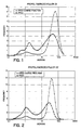
- Particle size distributions for two exemplary prepolymerized fillers having a bimodal size distribution are shown in FIGS. 1 and 2 , and are referred to as PPD1 and PPD2.
- a further reduction in shrinkage may be obtained by separating the small (fine) and large (coarse) particle size fractions and using the coarse particle fraction for the prepolymerized filler.
- An air classifier may be used to separate the fractions, such as a Cyclo-Tex, KC-21 model available commercially from Cyclotex Inc., Collinso Dominguez, CA, which is of cast iron construction and has a variable speed drive.
- the Cyclo-Tex machine is designed to operate with abrasive materials, and is grounded.
- the internal components are made mostly of stainless steel, low carbon steel, and urethane. Tungsten carbide wear blocks and tungsten carbide plasma spray is on many of the wear surfaces.
- the coarse discharge tubes are composed of TYGON ® and the fine discharge connector tube is made of urethane.
- the coarse or large fraction is collected, and comprises particles mostly above 10 ⁇ m, and an average particle size of about 30-70 ⁇ m.
- the coarse fraction advantageously contains less than about 15% by volume of particles smaller than 10 ⁇ m. Referring to FIGS. 1 and 2 , the coarse fraction of the air classified PPD1 and PPD2 are shown. It may be appreciated, however, that the particle size distribution will vary depending upon the starting materials used for the inorganic portion and the method of grinding.
- Test Samples 1-3 include ground structural filler, a 20 nm discrete nanofiller and prepolymerized filler in accordance with the present invention.
- Comparative Sample 1 includes ground structural filler and 20 nm and 40 nm nanofillers (microfillers) of the prior art.
- Comparative Sample 2 includes ground structural filler, a 20 nm discrete nanofiller and a 20 nm nanofiller (microfiller) of the prior art.
- the five composites were prepared as described below.
- the filler material to be milled in this case BAG (barium aluminoborosilicate glass, type SP-345, Specialty Glass, Oldsmar, FL), was charged into a vibratory mill from Sweco (Florence, KY), as described in U.S. Patent Nos. 5,979,805 and 6,098,906 , incorporated herein by reference in their entirety.
- the vibratory mill was filled with glass media and water, and the mill was vibrated to comminute the particles.
- the mean particle size is measured, typically by laser scattering.
- Laser scattering is a method of measuring mean particle size by sensing the average relative angular intensity of scattered light. A beam of monochromatic light with a uniform wave front is directed at the sample, the light is diffracted or scattered by the particles and a detector is used to measure the relative average intensity of the scattered light at various angles. The mean particle size and size distribution may then be calculated from the relative average intensity.
- One such laser scattering device is disclosed in U.S. Patent No. 5,610,712 to Schmitz et al. , incorporated herein by reference in its entirety. For the present example, a Horiba Model 2A-910 Laser Scattering Mean Particle Size Analyzer was used.
- the resulting structural filler is as follows: 10% by volume of the filler particles have a mean particle size of less than 0.28 ⁇ m; 50% by volume of the filler particles have a mean particle size less than 0.44 ⁇ m; and 90% by volume of the filler particles have a mean particle size less than 0.66 ⁇ m.
- This filler is referred to henceforth as a 0.4 ⁇ m structural filler.
- the slurry was then dried at 110°C and the dried cake was sieved through a 100 mesh (150 ⁇ m) plastic screen.
- the ground glass was then silanated by spraying in a V-blender with a 20% hydrolyzed solution of MEMO in water to make the powder hydrophobic.
- the loading of the silane in the filler was 2.5% by weight.
- the prepolymerized filler for inclusion in Test Samples 1 and 2 was prepared with the components listed in Table 2.
- Resin 2 listed in Table 1 was combined with a 0.7 ⁇ m silane treated BAG filler and a 40 nm silane treated fumed silica and mixed in a planetary mixer followed by deaeration to form a paste.
- the paste was then layered into sheets and heat polymerized for 4 hours in a convection oven heated to 100°C.
- the resultant polymerized mass was ground using a ceramic ball mill to give prepolymerized filler particles having a particle size distribution as shown in FIG. 1 ., referred to as PPD1.
- the fine particle fraction has an average particle size of about 1.8
- the course particle fraction has an average particle size of about 40 ⁇ m.
- the prepolymerized filler for inclusion in Test Sample 3 was prepared using the coarse fraction of the PPD1 filler used in Test Samples 1 and 2, the coarse fraction obtained using the air classifier Cyclo-Tex, KC-21 described above.
- the PPD 1 filler was run in an open atmosphere, and hand fed at a low feed rate.
- the classifier was operated at 4500 rpm, with a 5% throttle opening and a 2 hole (1 3 ⁇ 8 inch each) air inlet restrictor plate.
- a large blower (5 horsepower, 3500 rpm, radial blade) was running through a bag house filter.
- the coarse fraction size distribution is shown in FIG. 1 .
- the discrete nanofiller used for the Test Samples 1-3 and Comparative Sample 2 was Nalco 2327 made of silica and having a diameter of about 20 nm.
- the nanofiller particles are discrete and non-aggregated.
- the nanopowder was first treated as follows: In a 10 inch drying dish, 250 g Nalco 2327 slurry, 300 g methoxypropanol (Dowanol ® PM from Dow Chemical Co.) and 3.8 g MEMO were stirred for 30 min., followed by evaporation at 80°C at 80 mbar for 5 hours and then for 16hours at 80°C and 1-2 mbar. The resultant residue was screened through a 90 ⁇ m plastic screen.
- Comparative Samples 1 and 2 were hydrophobic fumed silicas, specifically US202 (available commercially from Degussa Corp., Ridgefield Park, NJ), having an average particle size of 20 nm (Comparative Samples 1 and 2) and OX-50 (also available commercially from Degussa Corp., Ridgefield Park, NJ) having an average particle size of 40 nm (Comparative Sample 1).
- the OX-50 was silanated by spraying in a V-blender with a 20% hydrolyzed solution of MEMO in water to make the powder hydrophobic.
- the loading of the silane in the OX-50 was 5% by weight.
- a light-curable resin base material which may include commercially available monomers containing methacrylate groups.
- TABLE 1 lists the components of the resins that were used in the five composites. Pigments such as titanium dioxide may be added to control optical properties of the composite.
- RESIN COMPOSITIONS COMPONENT Resin 1 (Wt. %) Resin 2 (wt. %) Resin 3 (Wt. %) BisGMA (Bisphenol A Diglycidyl ether dimethacrylate) 3.0 49.4 10.0 Ethoxylated Bisphenol A Dimethacrylate (No.
- Suitable monomers may be used in the resin composition, such as diethylene glycol dimethacrylate, tetraethylene glycol dimethacrylate, 1,12-dodecanediol dimethacrylate, diurethane dimethacrylate (Rohamere 6661-0, Huls America, Somerset, NJ), trimethylolpropane trimethacrylate, glyceryl dimethacrylate, and neopentylglycol dimethacrylate.
- diethylene glycol dimethacrylate tetraethylene glycol dimethacrylate
- 1,12-dodecanediol dimethacrylate 1,12-dodecanediol dimethacrylate
- diurethane dimethacrylate Roshamere 6661-0, Huls America, Somerset, NJ
- trimethylolpropane trimethacrylate trimethylolpropane trimethacrylate
- glyceryl dimethacrylate glyceryl dim
- the resin is introduced into a planetary mixer thermostated at 50°C.
- a polycaprolactone-modified methacrylate monophosphate dispersant was added to the resin in an amount of 2 wt.% in accordance with U.S. Patent No. 6,300,390 , incorporated by reference herein in its entirety.
- a polycaprolactone-modified ethyl methacrylate phosphate dispersant was used, which was prepared with a 5:1 molar ratio of caprolactone units to hydroxyethyl methacrylate, followed by phosphorylation.
- the planetary mixer is then started and the filler containing the physically admixed components listed in Table 3 below are added slowly over a period of three hours.
- the composite is subsequently mixed for another hour and then de-aerated under attenuated oxygen pressure.
- the surface of the tooth is prepared by removing any portion of the tooth enamel, and if necessary the dentin, that is decayed or damaged. A retention groove is then formed in the dentin if needed to maintain the restoration on the tooth. The practitioner then adds opacifiers and pigments to match the color of the composite with the color of the tooth. The composite is then built up on the surface of the tooth to replace any lost material. Once the practitioner is satisfied with the appearance of the restoration the composite is exposed to a visible light source to cure the resin and activate the adhesive by crosslinking the polymer matrix. After the composite has been cured, the surface is polished.
- a 157 mm 3 disk-shaped sample of paste is sandwiched between a cover glass plate 1.8 mm thick and a glass cover slip of 0.2 mm thick.
- a non-contact brass ring-shaped spacer 1.0 mm thick is used.
- an LDVT transducer with a 2g probe mass is in contact with the glass slip and measures the dimensional change after polymerization for 20 seconds from a Demetron 401 dental curing light with an 11 mm tip situated underneath the glass plate. The measurement after 5, 10 and 60 seconds is recorded. 6 Buoyancy method in water was used. The shrinkage was measured by the difference of densities before and after cure for a 0.5g disk-shaped sample. The average of 3 samples is reported.
- composites of the present invention have a volume loading greater than about 65%.
- composites including the prepolymerized fillers in accordance with the present invention resulted in lower viscosity, as evidenced by the penetrometer measurements.
- the total filler loading for composites of the present invention includes a portion that is inorganic and a portion that is organic.
- the organic portion is the resin in the prepolymerized filler, and the inorganic portion is the remainder, e.g., the BAG and silica.
- the comparative samples do not have an organic portion contributing to the filler loading.
- the total inorganic load of the test samples was approximately the same as the inorganic load and the total load of Comparative Sample 1, yet the test samples exhibited drastically lower shrinkage. The reduction in shrinkage can thus be at least partially attributed to the prepolymerized filler, and more specifically, to the presence of an organic portion in the filler. It is also notable that higher gloss was obtained in the Test Samples compared to Comparative Sample 1, despite the use of 0.7 ⁇ m BAG filler in the prepolymerized filler component.
- Test Sample 3 which used the air classified coarse fraction of the bimodal prepolymerized filler exhibited even lower shrinkage than Test Samples 1 and 2, which used the unclassified fine and coarse fractions of the bimodal prepolymerized filler.
- An increase in hardness, flexural strength and flexural modulus was also observed, as well as lower viscosity as evidenced by the penetrometer measurement.
- the dental composite of the present invention provides a restoration having the high strength from high filler loading and reduced shrinkage upon curing while providing translucency and surface gloss useful in cosmetic restorations.
- the dental composite of the present invention provides the luster and translucency of dispersion reinforced composites with the strength of hybrid composites.
Landscapes
- Health & Medical Sciences (AREA)
- Oral & Maxillofacial Surgery (AREA)
- Epidemiology (AREA)
- Life Sciences & Earth Sciences (AREA)
- Animal Behavior & Ethology (AREA)
- General Health & Medical Sciences (AREA)
- Public Health (AREA)
- Veterinary Medicine (AREA)
- Chemical & Material Sciences (AREA)
- Inorganic Chemistry (AREA)
- Plastic & Reconstructive Surgery (AREA)
- Dental Preparations (AREA)
Description
- The present invention generally relates to composite resin materials for use in dental restorations, and more particularly to a universal composite resin material incorporating a structural filler, a prepolymerized filler, and a discrete nanoparticle sized filler to provide a composite of high strength, improved loading and reduced shrinkage in clinical use.
- In dentistry, practitioners use a variety of restorative materials, for example to create crowns, veneers, direct fillings, inlays, onlays and splints. Composite resins are a type of restorative material which are suspensions of strengthening agents, such as mineral filler particles, in a resin matrix. These materials may be dispersion reinforced, particulate reinforced, or hybrid composites.
- Dispersion reinforced composites include a reinforcing filler having a mean particle size of about 0.05 µm or less, with a filler loading of about 30%-45% by volume. However, loading of the dispersion-reinforcing filler into the resin is limited by the ability of the resin to wet the filler due to the small particle size and high surface area of this type of reinforcing filler. Consequently, the filler loading is limited to about 45% by volume. Due to the low loading, the filler particles are not substantially in contact with one another. Thus, the primary reinforcing mechanism of such dispersion-reinforced composites is by dislocation of flaws in the matrix around the filler. In dispersion-reinforced materials, the strength of the resin matrix contributes significantly to the total strength of the composite. In dentistry, dispersion reinforced composite resins or microfills are typically used for cosmetic restorations due to their ability to retain surface luster. Typically, these microfill resins use free radical-polymerizable resins such as methacrylate monomers, which, after polymerization, are much weaker than the dispersed filler. Despite the dispersion reinforcement, microfill resins are structurally weak, limiting their use to low stress restorations.
- Microfills generally use prepolymerized filler material for dispersion reinforcement, as described in
U.S. Patent Nos. 4,389,497 ,4,781,940 and6,020,395 . Generally, prepolymerized filler is produced by mixing finely divided silica with a polymerizable monomer, heat polymerizing the mixture in bulk, and pulverizing or grounding the mixture down to the desired agglomerate size to give a filler material comprising splintered polymerized particles. Polymerized particle sizes are large, generally greater than 1 µm in diameter, allowing for better reinforcement but a less stable, less glossy surface. The polymerized particles or prepolymerized filler material is then mixed with a polymerizable monomer, typically an acrylate or methacrylate-based resin, and an additional filler material, such as colloidal or fumed silica, to form the final microfill dental composite. - Particulate reinforced composites typically include a reinforcing filler having an average particle size greater than about 0.6 µm and a filler loading of about 60% by volume. At these high filler loadings, the filler particles begin to contact one another and contribute substantially to the reinforcing mechanism due to the interaction of the particles with one another and to interruption of flaws by the particles themselves. These particulate reinforced composite resins are stronger than microfill resins. As with the dispersion-reinforced composites, the resin matrix typically includes methacrylate monomers. However, the filler in particulate reinforced composites has a greater impact on the total strength of the composite, such that the particulate reinforced composites have been used for stress bearing restorations.
- Another class of dental composites, known as hybrid composites, include the features and advantages of dispersion reinforcement and those of particulate reinforcement. Hybrid composite resins contain fillers having an average particle size of 0.6 µm or greater with a microfiller having an average particle size of about 0.05 µm or less. HERCULITE® XRV (Kerr Corp.) is one such example. HERCULITE® has been considered by many as an industry standard for hybrid composites. It has an average particle size of 0.84 µm and a filler loading of 57.5% by volume. The filler is produced by a wet milling process that produces fine particles that are substantially contaminant free. About 10% of this filler exceeds 1.50 µm in average particle size. In clinical use, the surface of HERCULITE® turns to a semi-glossy matte finish over time. Because of this, the restoration may become distinguishable from normal tooth structure when dry, which is not desirable for a cosmetic restoration.
- Various methods of forming submicron particles, such as precipitation or sol gel methods, are available to produce particulate reinforcing fillers for hybrid composites. However, these methods do not restrict the particle size to at or below the wavelength of light (about 0.5 µm) to produce a stable glossy surface.
U.S. Patent No. 6,121,344 , describes a resin-containing dental composite including a structural filler of ground particles having an average particle size of between about 0.05 µm and about 0.5 µm that has the high strength required for load-bearing restorations. Because the structural filler particles are ground, the particles are nonspherical, providing increased adhesion of the resin to the structural filler, thereby further enhancing the overall strength of the composite. Through the use of ground structural filler particles having an average particle size less than the wavelength of light, the dental composite exhibits the luster and translucency required for cosmetic restorations. - In
U.S. Patent No. 6,121,344 , fumed silica having an average particle size less than about 0.05 µm are added, preferably between about 1% by weight and about 15% by weight of the composite. The microfill particles contribute to dispersion reinforcement, fill the interstices between the larger structural filler particles reducing occluded volume, and provide a large surface area to be wetted by the resin to increase strength. The fumed silica microfill particles also contribute to the flow properties of the uncured resin. Fumed silica is produced by hydrolysis of silicon tetrachloride vapor in a flame of hydrogen and oxygen. During this process, silicon dioxide molecules condense to form particles of size usually less than 50 nm. The particles then attach to each other and sinter together. Due to the nature of the flame process, a three-dimensional chain aggregate with a length of 200-300 nm forms. Further mechanical entanglement occurs upon cooling to give agglomerates. Attractive interactions between surface silanol groups of the particles give thixotropic properties to liquids in which these fumed silicas are suspended. The fumed silicas are hydrophobically treated to make it compatible with resins employed, however, treatment is usually not complete and residual unreacted silanol groups typically remain, resulting in substantial interactions of these groups with other reactive groups in the composite. The particle-particle interaction prevents homogenous dispersion of the microfiller in the resin matrix and increases the viscosity of the suspension, which correspondingly decreases the workability of the composite paste. This places a limitation on the practical filler loading in fumed silica microfilled restorative composites. A high filler loading is desirable in dental restorations because the high loading provides a paste with improved handling properties over a paste with low filler loading. Moreover, higher loading gives a composite that experiences lower shrinkage upon curing and has a coefficient of thermal expansion better matching that of a natural tooth. - Resin shrinkage upon polymerization, however, is a problem that has faced composites of the prior art incorporating dispersion reinforced, particulate reinforced and hybrid filler materials. The resin matrix shrinks upon polymerization during the curing process. Polymerization shrinkage, both axial and volumetric, generally results from the conversion of the carbon-carbon double bonds of low molecular weight monomers in the polymeric composite to corresponding carbon-carbon single bonds of crosslinked polymers during the curing reaction. Such shrinkage tends to cause gap formation between the restorative composite and the tooth, leading to microleakage, secondary caries and decreased longevity of the repair.
- The resin-containing dental composites described herein have high filler loading and reduced shrinkage while being mechanically strong and effective for stress bearing and cosmetic restorations without exhibiting the drawbacks of the prior art dental composites.
- There is thus a need to develop a hybrid dental restorative composite that has a physical make-up to afford high filler loading, appropriate viscosity for good workability of the composite paste, and lower shrinkage during polymerization.
-
EP 0368657 discloses a dental restorative material comprising a resin base and filler. The filler may comprise a nanofiller, a prepolymerized filler and a ground structural filler with a particle size range of 0-1-100 µm. - The present invention provides a dental composite comprising a polymerizable resin base and 10% by volume to 80% by volume filler comprising a ground structural filler, a prepolymerized filler and a nanofiller, wherein the structural filler comprises between 10% by volume and 70% by volume of the composite and consists of particlesthat have been ground to a mean particle size between 0.05 µm and 0.50 µm, wherein the ground structural filler contains less than 50% by volume of particles above 0.5 µm in diameter , wherein the prepolymerized filler comprises at least 1% by volume of the composite and consists of an inorganic portion and a polymerized organic resin portion, and wherein the nanofiller comprises at least 0.01% by volume of the composite, the nanofiller comprising discrete, non-aggregated particles of mean particle size less than 100 nm. Also provided is a method for making a dental composite paste.
- The structural filler comprises between about 10% and about 70% by volume of the composite, and advantageously between about 20% and about 60% by volume, and because the structural filler is ground, the particles are non-spherical, providing increased adhesion of the resin to the structural filler thereby enhancing the overall strength of the composite. Further, by virtue of the particles having a mean particle size less than the wavelength of light, that is less than about 0.5 µm, the structural filler contributes to the luster and translucency of the composite required for cosmetic restorations. In an exemplary embodiment, the ground structure filler contains less than 50% by volume of particles above 0.5µm in diameter.
- The discrete, non-agglomerated nanofiller particles comprise at least about 0.01 % by volume of the composite, and advantageously between about 1% and about 15% by volume, and contribute to dispersion reinforcement, fill the interstices between the larger structural filler particles reducing occluded volume, and provide a large surface area to be wetted by the resin to increase strength. In addition, particle-particle interactions are minimized, thereby allowing for high filler loading and lower shrinkage upon curing.
- The prepolymerized filler comprises at least about 1% by volume of the composite, and advantageously about 1% to about 60% by volume, and allows for an increased total filler loading in the composite by virtue of the low surface area of the prepolymerized filler relative to the other fillers. The prepolymerized filler particles are prepared by mixing an inorganic filler with an organic polymerizable resin and curing the mixture. The cured mixture is then ground to a desired size, for example a bimodal particle size distribution including a fine particle fraction of mean particle size in the range of about 1 µm to about 3 µm and a coarse particle fraction of mean particle size in the range of about 30 µm to about 70 µm, at least about 95% of the particles of size less than about 100 µm. The ground bimodal prepolymerized filler may be further air classified to separate the fine particle fraction from the coarse particle fraction to provide the prepolymerized filler with a coarse particle size distribution including a mean particle size in the range of about 30 µm to about 70 µm, at least about 90% of the particles of size less than about 100 µm, and at least about 85% of the particles of a size greater than about 10 µm. The prepolymerized filler enhances the polydispersity of the composite paste, thereby enabling the higher filler loading and improving the handling properties of the paste. The non-spherical surface of the ground particles provides additional adhesion between the prepolymerized filler and the resin, thereby further strengthening the cured composite. Further, a reduction in shrinkage upon curing of the composite is provided by virtue of inclusion of the prepolymerized filler, thereby increasing the tooth-composite marginal integrity.
- As used herein, "consists essentially" precludes fillers of other components which would materially affect the basic characteristics of the composite.
- The present invention will now be described, by way of example, with reference to the accompanying drawings, in which:
-
FIGS. 1 and 2 are particle size distributions for two exemplary prepolymerized fillers used in composites of the present invention, each including an unclassified bimodal filler and a classified coarse filler. - The present invention provides a dental restorative composite comprising a ground structural filler having a mean particle size between about 0.05 µm and about 0.50 µm, wherein the ground structural filler contains less than 50% by volume of particles above 0,5 µm, a prepolymerized filler, and a discrete nanofiller having a mean particle size less than about 100 nm in a curable resin, such as a resin containing polymerizable methacrylate monomers. Generally, the resinous composite is cured by mixing two paste components containing a catalyst and an accelerator, respectively, or by a photopolymerization process wherein the resins are exposed to actinic radiation, such as blue visible light. Photopolymerizable resins containing monomers other than methacrylates, such as cationically photocurable oxiranes, for example, may be used in the present invention as persons of ordinary skill in the art would appreciate. The resinous dental composite is generally applied to one or more teeth by the dental practitioner and cured by exposure to visible light. The composite cures with a low shrinkage, such as about 2% or less, which is a significant improvement over prior hybrid composites.
- To provide the ground structural filler having a mean particle size of less than 0.5 µm, an extensive comminution step is required. Comminution may be performed in an agitator mill, and advantageously an agitator mill designed to minimize contamination, such as that described in
U.S. Patent No. 6,010,085 . Alternatively, comminution may be performed in a vibratory mill, and advantageously in a vibratory mill designed to minimize contamination, such as described inU.S. Patent Nos. 5,979,805 and6,098,906 . Comminution deagglomerates the structural filler particles by separating particles from clusters, decreases the size of the structural filler particles, eliminates large particles by breakage and increases the specific surface area of the structural filler particles by producing a large quantity of very fine particles. Size reduction with an agitator mill or vibratory mill occurs due to a combination of impact with the milling media, abrasion with the milling media and attrition of the particles. - Structural fillers suitable for use in the present invention include barium magnesium aluminosilicate glass, barium aluminoborosilicate glass (BAG), amorphous silica, silica-zirconia, silica-titania, barium oxide, quartz, alumina and other inorganic oxide particles. The mean particle size of the structural filler is limited to less than the wavelength of light to prevent the structural filler from decreasing surface gloss after substantial brushing. However, it is expected that as the particle size is reduced below about 0.05 µm the strength needed for load-bearing restorations demises due to increasing occluded volume of resin. Currently, it is believed that a mean particle size between about 0.05 µm and about 0.5 µm provides the best balance between optical and structural properties.
- Nanofillers suitable for use in the present invention include powders with particles that are not aggregated or substantially agglomerated so as to minimize particle-particle interactions. The discrete particles have a mean particle size less than 100 nm. By "discrete particles," there are included weakly agglomerated particles having an agglomerated average size less than 100 nm. For example, Nanomaterials Research Corp., Longmont, CO, manufactures an aluminosilicate powder having a mean particle size of about 80 nm and a 1:4 molar ratio of alumina to silica. This nanofiller has a refractive index of 1.508.
- By way of further example, Nalco Chemical Co., Naperville, IL, provides nanofiller particles having a mean particle size of about 20 nm, which are sold under the commercial designation of Nalco 2327. This nanofiller has a refractive index of 1.48. By way of yet a further example, Nanophase Technologies Corp., Romeoville, IL, manufactures gamma alumina powders having mean particle sizes less than 20 nm, as well as a powder having a mean particle size of 38 nm. This nanofiller has a refractive index of about 1.71. The powder is produced by a physical vapor synthesis process, such as that described in
U.S. Patent Nos. 5,874,684 ;5,514,349 ; and5,460,701 . - The nanofiller particles may be surface treated, for example with gamma methacryloxypropyltrimethoxy silane (MEMO). The nanofiller comprises at least about 0.01% by volume of the dental composite, more advantageously about 1-15% by volume, and most advantageously about 5-12% by volume.
- Generally, the nanofiller should have a refractive index similar to that of the resin. Resins typically have a refractive index of about 1.48-1.55. Thus, the nanofiller should have a refractive index in the range of about 1.48-1.6. However, it is believed that for nanofillers of 20 nm particle size or less, the refractive index may vary from that of the filler without negatively affecting the optical properties of the dental composite.
- Prepolymerized fillers suitable for use in the present invention include particles having an inorganic portion and a polymerized organic resin portion. Advantageously, the inorganic portion is greater than the organic portion. The prepolymerized filler is present in the composite in an amount of at least about 1% by volume, and advantageously between about 1% and about 60% by volume, and more advantageously between about 10% and 40% by volume. A proper balance between the prepolymerized filler and ground structural filler enhances the polydispersity of the composite paste, which provides higher loading capability and improves the handling properties of the paste. In addition, higher loading reduces the hydrodynamic drag and viscosity of the uncured composite.
- The prepolymerized filler for use in the present invention may be prepared by a variety of conventional methods and may comprise filler materials traditionally used as reinforcing filler and/or microfiller and resins typically used for restorative composites. For example, fumed silica and BAG or other filler of desired size and characteristics may be mixed with polymerizable resin to prepare a paste. The paste is then heat polymerized and the resultant polymerized mass is ground to the desired particle size, for example, using a ceramic ball mill. Where the inorganic portion comprises a mixture of reinforcing filler and microfiller, the particles size distribution of the prepolymerized filler will likely be generally bimodal. For example, for a mixture of 40 nm microfiller and 0.7 µm reinforcing filler, a small (fine) particles size fraction will have a distribution centered around about 1-3 µm, and a large (coarse) particle size fraction will have a distribution centered around about 30-70 µm in size, with a volume ratio of approximately 30:70 percent, respectively. In an exemplary embodiment, at least about 90% of the particles of the prepolymerized filler have a size below about 100 µm, and advantageously at least about 95% are below about 100 µm. Particle size distributions for two exemplary prepolymerized fillers having a bimodal size distribution are shown in
FIGS. 1 and 2 , and are referred to as PPD1 and PPD2. - A further reduction in shrinkage may be obtained by separating the small (fine) and large (coarse) particle size fractions and using the coarse particle fraction for the prepolymerized filler. An air classifier may be used to separate the fractions, such as a Cyclo-Tex, KC-21 model available commercially from Cyclotex Inc., Rancho Dominguez, CA, which is of cast iron construction and has a variable speed drive. The Cyclo-Tex machine is designed to operate with abrasive materials, and is grounded. The internal components are made mostly of stainless steel, low carbon steel, and urethane. Tungsten carbide wear blocks and tungsten carbide plasma spray is on many of the wear surfaces. The coarse discharge tubes are composed of TYGON® and the fine discharge connector tube is made of urethane. Using the classifier, the coarse or large fraction is collected, and comprises particles mostly above 10 µm, and an average particle size of about 30-70 µm. The coarse fraction advantageously contains less than about 15% by volume of particles smaller than 10 µm. Referring to
FIGS. 1 and 2 , the coarse fraction of the air classified PPD1 and PPD2 are shown. It may be appreciated, however, that the particle size distribution will vary depending upon the starting materials used for the inorganic portion and the method of grinding. - The inclusion of a prepolymerized filler into a composite having a ground structural filler and a discrete, non aggregated nanofiller will minimize or reduce the total shrinkage of the composite when it is cured. Composites prepared and tested, as set forth in the examples below, reveal drastic reduction in composite shrinkage when compared to composites of the prior art. Shrinkages have ranged from about 2% and less upon curing of the composites of the present invention. Both axial and volumetric shrinkages may be less than 2%, and even as low as about 1.5-1.6% in the case of axial shrinkage measured at 60 seconds. Less shrinkage has tremendous benefits including prolonging the stability and strength of the cured composite while decreasing the need for repairs and replacement. Specifically, lower shrinkage during curing results in a smaller percentage of separation between the restoration and tooth structure. The result is a composite material with high tooth-composite marginal integrity, which in turn maximizes restorative longevity and minimizes secondary caries. Furthermore, inclusion of a prepolymerized filler decreases the viscosity of the uncured composite thereby improving its handling properties and adding convenience to the dental practitioner.
- The present invention will be further appreciated in light of the following examples.
- Five composite examples, including two comparative samples and three test samples, were prepared to illustrate the benefits of including prepolymerized filler in composites comprising a structural filler and a nanofiller. Test Samples 1-3 include ground structural filler, a 20 nm discrete nanofiller and prepolymerized filler in accordance with the present invention.
Comparative Sample 1 includes ground structural filler and 20 nm and 40 nm nanofillers (microfillers) of the prior art.Comparative Sample 2 includes ground structural filler, a 20 nm discrete nanofiller and a 20 nm nanofiller (microfiller) of the prior art. The five composites were prepared as described below. - To prepare the structural filler for inclusion into the five dental composites, the filler material to be milled, in this case BAG (barium aluminoborosilicate glass, type SP-345, Specialty Glass, Oldsmar, FL), was charged into a vibratory mill from Sweco (Florence, KY), as described in
U.S. Patent Nos. 5,979,805 and6,098,906 , incorporated herein by reference in their entirety. The vibratory mill was filled with glass media and water, and the mill was vibrated to comminute the particles. - When the filler slurry is removed from the mill, the mean particle size is measured, typically by laser scattering. Laser scattering is a method of measuring mean particle size by sensing the average relative angular intensity of scattered light. A beam of monochromatic light with a uniform wave front is directed at the sample, the light is diffracted or scattered by the particles and a detector is used to measure the relative average intensity of the scattered light at various angles. The mean particle size and size distribution may then be calculated from the relative average intensity. One such laser scattering device is disclosed in
U.S. Patent No. 5,610,712 to Schmitz et al. , incorporated herein by reference in its entirety. For the present example, a Horiba Model 2A-910 Laser Scattering Mean Particle Size Analyzer was used. The resulting structural filler is as follows: 10% by volume of the filler particles have a mean particle size of less than 0.28 µm; 50% by volume of the filler particles have a mean particle size less than 0.44 µm; and 90% by volume of the filler particles have a mean particle size less than 0.66 µm. This filler is referred to henceforth as a 0.4 µm structural filler. - The slurry was then dried at 110°C and the dried cake was sieved through a 100 mesh (150 µm) plastic screen. The ground glass was then silanated by spraying in a V-blender with a 20% hydrolyzed solution of MEMO in water to make the powder hydrophobic. The loading of the silane in the filler was 2.5% by weight.
- The prepolymerized filler for inclusion in
Test Samples Resin 2 listed in Table 1 was combined with a 0.7 µm silane treated BAG filler and a 40 nm silane treated fumed silica and mixed in a planetary mixer followed by deaeration to form a paste. The paste was then layered into sheets and heat polymerized for 4 hours in a convection oven heated to 100°C. The resultant polymerized mass was ground using a ceramic ball mill to give prepolymerized filler particles having a particle size distribution as shown inFIG. 1 ., referred to as PPD1. The fine particle fraction has an average particle size of about 1.8, and the course particle fraction has an average particle size of about 40 µm. - The prepolymerized filler for inclusion in
Test Sample 3 was prepared using the coarse fraction of the PPD1 filler used inTest Samples PPD 1 filler was run in an open atmosphere, and hand fed at a low feed rate. The classifier was operated at 4500 rpm, with a 5% throttle opening and a 2 hole (1 ⅜ inch each) air inlet restrictor plate. A large blower (5 horsepower, 3500 rpm, radial blade) was running through a bag house filter. The coarse fraction size distribution is shown inFIG. 1 . - The discrete nanofiller used for the Test Samples 1-3 and
Comparative Sample 2 was Nalco 2327 made of silica and having a diameter of about 20 nm. The nanofiller particles are discrete and non-aggregated. The nanopowder was first treated as follows: In a 10 inch drying dish, 250 g Nalco 2327 slurry, 300 g methoxypropanol (Dowanol® PM from Dow Chemical Co.) and 3.8 g MEMO were stirred for 30 min., followed by evaporation at 80°C at 80 mbar for 5 hours and then for 16hours at 80°C and 1-2 mbar. The resultant residue was screened through a 90 µm plastic screen. The prior art nanofillers (microfillers) included inComparative Samples Comparative Samples 1 and 2) and OX-50 (also available commercially from Degussa Corp., Ridgefield Park, NJ) having an average particle size of 40 nm (Comparative Sample 1). The OX-50 was silanated by spraying in a V-blender with a 20% hydrolyzed solution of MEMO in water to make the powder hydrophobic. The loading of the silane in the OX-50 was 5% by weight. - The 0.4 µm structural filler, the prepolymerized filler, and/or the nanofillers are then combined with a light-curable resin base material which may include commercially available monomers containing methacrylate groups. TABLE 1 lists the components of the resins that were used in the five composites. Pigments such as titanium dioxide may be added to control optical properties of the composite.
TABLE 1 RESIN COMPOSITIONS COMPONENT Resin 1 (Wt. %) Resin 2 (wt. %) Resin 3 (Wt. %) BisGMA (Bisphenol A Diglycidyl ether dimethacrylate) 3.0 49.4 10.0 Ethoxylated Bisphenol A Dimethacrylate (No. of ethoxy groups = 3.5) 71.1 - 24.6 Ethoxylated Bisphenol A Dimethacrylate (No. of ethoxy groups = 6.0) - - 59.2 Triethylene Glycol Dimethacrylate 24.7 49.4 5.0 Benzoyl peroxide - 0.75 - 2-Ethylhexyl-4-(dimethylamino)benzoate 0.49 - 0.49 Camphorquinone 0.17 - 0.17 2-Hydroxy-4-methoxy Benzophenone 0.49 0.49 0.49 Butylated Hydroxytoluene (BHT) 0.05 0.05 0.05 TOTAL 100 100 100 Viscosity, at 25 °C (Pa.s) 0.15 - 0.59 Refractive Index 1.518 1.508 1.529 TABLE 2 PREPOLYMERIZED FILLER COMPOSITIONS Wt.% 0.7 µm BAG Filler 70 Wt.% OX-50 Fumed Silica 5 Wt.% Resin 2 (Table 1) 25 TOTAL 100 Volume % Inorganic Load 54.6 - Other monomers may be used in the resin composition, such as diethylene glycol dimethacrylate, tetraethylene glycol dimethacrylate, 1,12-dodecanediol dimethacrylate, diurethane dimethacrylate (Rohamere 6661-0, Huls America, Somerset, NJ), trimethylolpropane trimethacrylate, glyceryl dimethacrylate, and neopentylglycol dimethacrylate.
- The resin is introduced into a planetary mixer thermostated at 50°C. A polycaprolactone-modified methacrylate monophosphate dispersant was added to the resin in an amount of 2 wt.% in accordance with
U.S. Patent No. 6,300,390 , incorporated by reference herein in its entirety. Specifically, a polycaprolactone-modified ethyl methacrylate phosphate dispersant was used, which was prepared with a 5:1 molar ratio of caprolactone units to hydroxyethyl methacrylate, followed by phosphorylation. The planetary mixer is then started and the filler containing the physically admixed components listed in Table 3 below are added slowly over a period of three hours. The composite is subsequently mixed for another hour and then de-aerated under attenuated oxygen pressure. - In forming a restoration using the composite of the present invention, the surface of the tooth is prepared by removing any portion of the tooth enamel, and if necessary the dentin, that is decayed or damaged. A retention groove is then formed in the dentin if needed to maintain the restoration on the tooth. The practitioner then adds opacifiers and pigments to match the color of the composite with the color of the tooth. The composite is then built up on the surface of the tooth to replace any lost material. Once the practitioner is satisfied with the appearance of the restoration the composite is exposed to a visible light source to cure the resin and activate the adhesive by crosslinking the polymer matrix. After the composite has been cured, the surface is polished.
- TABLE 3 provides the testing results of the four composites. All measurements were carried out using standard ISO methods except where indicated, and the standard deviations are provided in parentheses. Standard ISO method 4049 for resin-based filling materials was used whenever possible.
TABLE 3 Comparative Sample 1Comparative Sample 2Test Sample 1Test Sample 2Test Sample 3Resin Resin 1 Resin 1Resin 3Resin 3Resin 3Wt.% Nanofiller (Vol. %) 4% OX-50 + 3% US202 (6.5) 12% Nalco 23271 + 2% US202 (13.3) 11.7 % Nalco 23271 (10.6) 12% Nalco 23271 (10.9) 12% Nalco 23271 (11) Wt.% Prepolymerized Filler (Vol. %) 0 0 26.38 (26.5) 26.5 (26.4) 27 (27.1) Wt.% 0.4 µm BAG2 filler (Vol. %) 69.5 (50.2) 66 (49.0) 44.9 (32) 44.5 (31.7) 44.5 (31.8) Wt.% Dispersant 2 2 2 2 2 Wt.% Total Load (Vol. %) 76.5 (56.7) 80.0 (62.3) 83.0 (69.0) 83.0 (69.0) 83.5 (69.9) Wt.% Total Inorganic Load (Vol. %) 76.5 (56.7) 80.0 (62.3) 76.4 (57.1) 76.4 (57.1) 76.41 (57.1) % Translucency3 35.0 41.0 40.1 39 - Vicker's Hardness4 (N/mm2) 585 (7) 702 (10) 518 (2) 595 (3) 598 (3) Flexural Strength (MPa) 126 (18) 121 (11) 93 (8) 118 (9) 134 (11) Flexural Modulus (MPa) 10004 (362) 11667 (219) 9854 (406) 11009 (489) 12057 (570) % Axial shrinkage at 60 sec5 2.71 (0.08) 2.26 (0.04) 1.52 (0.03) 1.57 (0.04) 1.45 (0.04) % Axial shrinkage at 10 sec5 2.29 (0.07) 1.87 (0.04) 1.23 (0.04) 1.1 (0.01) 1.10 (0.07) % Axial shrinkage at 5 sec5 1.65 (0.05) 1.45(0.04) 0.93 (0.05) 0.89 (0.01) 0.86 (0.07) % Volumetric shrinkage (Bouyancy Method6) 3.11 (0.01) -- -- 1.82 (0.07) 1.58 (0.06) Gloss, 60 degrees7 32.5 (1.9) -- -- 41 (0.5) 40.5 (0.6) Penetrometer (mm) 0g, 1mm flathead8 >8.0 5.4 2.9 2.5 1.3 1 5% MEMO coated.
2 BAG-Barium Aluminosilicate Glass.
3 Samples 20 mm in diameter and 1 mm in thickness were cured on each side for 60 seconds with a tungsten halogen lamp. The translucency was then measured in the transmission mode using a TCS Colorimeter (BYK-Gardner, Columbia, MD), by recording the Y value after the sample was placed on the transmission accessory.
4 Average of 3 measurements on the top surface of acylindrical sample 10 mm in diameter and 2 mm in height. The samples were light cured for 40 seconds and stored in water for 24 hours at 37°C prior to measurement.
5 The bonded disk method of D.C. Watts and A.J. Cash (Dent. Mater. 7, 281 (1991)) was used. A 157 mm3 disk-shaped sample of paste is sandwiched between a cover glass plate 1.8 mm thick and a glass cover slip of 0.2 mm thick. A non-contact brass ring-shaped spacer 1.0 mm thick is used. On top, an LDVT transducer with a 2g probe mass is in contact with the glass slip and measures the dimensional change after polymerization for 20 seconds from a Demetron 401 dental curing light with an 11 mm tip situated underneath the glass plate. The measurement after 5, 10 and 60 seconds is recorded.
6 Buoyancy method in water was used. The shrinkage was measured by the difference of densities before and after cure for a 0.5g disk-shaped sample. The average of 3 samples is reported.
7 Cured samples were prepared with the dimensions of 20x40x2mm and were sanded with wet #600 silicon carbide paper (3M, St. Paul, MN) under water until a constant gloss value was obtained. A Leco Spectrum 2000 grinder and polisher (St. Joseph, MI) was used with an orbital speed of 80 rpm and a head speed of 25 rpm for 1.5 min. and 3 lbs of pressure. The gloss of the surface was measured using a Micro-Tri-Gloss apparatus (BYK-Gardner USA, Columbia, MD), which performs a photoelectric measurement of specularly reflected light from a surface. This instrument was calibrated according to ISO standard 2813. The measurement angle was 60 degrees. An average of three measurements is reported.
8 Precision Penetrometer (GCA Corp., Chicago, IL) with a 1 mm flat head was used with no additional weight (0g). The paste was placed in amold 10 mm in diameter and 8 mm in height. Penetration was performed for 10 seconds. An average of 3 measurements is reported. - For the
comparative sample 2 containing the 0.4 µm structural filler and a discrete nanofiller, an increase in filler loading and reduction in shrinkage is achieved compared to thecomparative sample 1 with the same structural filler but a nanofiller of the prior art. For the test dental composites containing a 0.4 µm structural filler, a prepolymerized filler, and a discrete nanoparticle filler, in accordance with the present invention, the addition of prepolymerized filler led to an even greater increase in filler loading capacity and a significant reduction in shrinkage. Particularly, both the axial and volumetric shrinkage was reduced by about 25% or more from the comparative composites. The reduction in shrinkage observed in the above examples is believed to be attributable at least in part to the higher volume loading. Advantageously, composites of the present invention have a volume loading greater than about 65%. In addition, composites including the prepolymerized fillers in accordance with the present invention resulted in lower viscosity, as evidenced by the penetrometer measurements. - The total filler loading for composites of the present invention includes a portion that is inorganic and a portion that is organic. The organic portion is the resin in the prepolymerized filler, and the inorganic portion is the remainder, e.g., the BAG and silica. The comparative samples do not have an organic portion contributing to the filler loading. The total inorganic load of the test samples was approximately the same as the inorganic load and the total load of
Comparative Sample 1, yet the test samples exhibited drastically lower shrinkage. The reduction in shrinkage can thus be at least partially attributed to the prepolymerized filler, and more specifically, to the presence of an organic portion in the filler. It is also notable that higher gloss was obtained in the Test Samples compared toComparative Sample 1, despite the use of 0.7 µm BAG filler in the prepolymerized filler component. - In addition,
Test Sample 3, which used the air classified coarse fraction of the bimodal prepolymerized filler exhibited even lower shrinkage thanTest Samples - The tests described above used small-scale prepared pastes and the formulas were not especially optimized with respect to the extent of mixing. More intense mixing methods and variations in the nanoparticle surface treatment are expected to further increase volume loading of the fillers, which is likewise expected to lead to further reduction in shrinkage. Also, it should be understood that the translucency of a paste increases typically upon aging due to "wetting out" of the filler. This "wetting out" effect is expected to be more pronounced with nanofillers due to the smaller inclusions between them for which the resin takes longer to enter.
- Thus, the dental composite of the present invention provides a restoration having the high strength from high filler loading and reduced shrinkage upon curing while providing translucency and surface gloss useful in cosmetic restorations. Through the use of structural filler particles having a mean particle size less than the wavelength of light, yet large enough to provide strength, the dental composite of the present invention provides the luster and translucency of dispersion reinforced composites with the strength of hybrid composites. Through the use of prepolymerized filler in combination with discrete, non-aggregated nanoparticles and the structural filler, improved physical properties may be obtained, and significantly less shrinkage occurs upon polymerization.
- While the present invention has been illustrated by a description of various embodiments and while these embodiments have been described in considerable detail, additional advantages and modifications will readily appear to those skilled in the art.
Claims (31)
- A dental composite comprising a polymerizable resin base and 10% by volume to 80% by volume filler comprising a ground structural filler, a prepolymerized filler, and a nanofiller, wherein the structural filler comprises between 10% by volume and 70% by volume of the composite and consists of particles that have been ground to a mean particle size between 0.05 µm and 0.50 µm, wherein the ground structural filler contains less than 50% by volume of particles above 0.5 µm in diameter , wherein the prepolymerized filler comprises at least 1% by volume of the composite and consists of an inorganic portion and a polymerized organic resin portion, and wherein the nanofiller comprises at least 0.01% by volume of the composite, the nanofiller comprising discrete, non-aggregated particles of mean particle size less than 100 nm.
- The dental composite of claim 1, wherein the prepolymerized filler comprises between 10% and 40% by volume of the composite.
- The dental composite of either claim 1 or claim 2, wherein the nanofiller comprises between 5% and 12% by volume of the composite.
- The dental composite of any preceding claim, wherein the nanofiller comprises, preferably consists essentially, of discrete particles selected from the group consisting of aluminosilicate particles, gamma alumina particles, silica particles, and combinations thereof.
- The dental composite of claim 4, wherein the nanofiller comprises, preferably consists essentially, of silica particles having a mean particle size of 20 nm or less.
- The dental composite of claim 4, wherein the nanofiller comprises, preferably consists essentially, of aluminosilicate particles having a mean particle size of 80 nm or less.
- The dental composite of claim 4, wherein the nanofiller comprises, preferably consists essentially of, gamma alumina particles having a mean particle size of 20 nm or less.
- The dental composite of any preceding claim, wherein the prepolymerized filler comprises, preferably consists essentially, of particles having a particle size distribution including a mean particle size in the range of 30 µm to 70 µm, at least about 90% of the particles of size less than 100 µm, and at least 85% of the particles of a size greater than 10 µm.
- The dental composite of any one of claims 1 to 7 wherein the prepolymerized filler comprises, preferably consists essentially of, particles having a bimodal particle size distribution including a fine particle fraction of mean particle size in the range of 1 µm to 3 µm and a coarse particle fraction of mean particle size in the range of 30 µm to 70 µm, at least 95% of the particle of size less than 100 µm.
- The dental composite of any preceding claim, wherein the prepolymerized filler particles comprises silica as the inorganic portion and a methacrylate base resin as the polymerized organic resin portion.
- The dental composite of claim 1 wherein the ground structural filler comprises between 20% by volume and 60% by volume of the composite, wherein the prepolymerized filler comprises between 10% and 40% by volume of the composite and consists essentially of ground polymerized particles having a mean particle size in the range of from 30 µm to 70 µm, and wherein the prepolymerized filler contains at least 90% of the particles of size less than 100 µm, and at least 85% of the particles of a size greater than 10 µm, and wherein the nanofiller comprises between 5% by volume to 12% by volume of the composite and comprises, preferably consists essentially, of discrete, non-aggregated particles of mean particle size less than 50 nm.
- The dental composite of claim 11, wherein the nanofiller consists essentially of silica particles having a mean particle size of 20 nm.
- The dental composite of claim 1 comprising 22% by volume to 80% by volume filler in the resin base, wherein the ground structural filler comprises between 20% by volume and 70% by volume of the composite, wherein the prepolymerized filler comprises from 1% to 60% by volume of the composite and comprises ground polymerized particles having particle size distribution having at least a first average particle size peak centered in the range of 30 µm to 70 µm, wherein the nanofiller comprises between 1% by volume and 15% by volume of the composite.
- The dental composite of claim 13, wherein the prepolymerized filler consists essentially of particles having at least 90% of the particles of size less than 100 µm, and at least 85% of the particles of a size greater than 10 µm.
- The dental composite of claim 13, wherein the prepolymerized filler consists essentially of particles having a bimodal particle size distribution including a second average particle size peak centered in the range of 1 µm to 3 µm and at least 95% of the particles of size less than 100 µm.
- The dental composite of any preceding claim, wherein the resin base comprises a polymerizable vinyl compound.
- A method of making a dental composite paste for use in restoring a tooth, the method comprising preparing a prepolymerized filler by mixing an inorganic filler with an organic polymerizable resin, curing the mixture, and then grinding the cured mixture, providing a structural filler consisting of particles that have been ground to a mean particle size between 0.05 µm and 0.50 µm, wherein the ground structural filler contains less than 50% by volume of particles above 0.5 µm in diameter, providing a discrete nanofiller comprising discrete, non-aggregated particles of mean particle size less than 100 nm, mixing the structural filler, prepolymerized filler and discrete nanofiller with a polymerizable resin base to form a dental composite paste having a total filler loading between 10% by volume and 80% by volume, wherein the structural filler comprises between 10% by volume and 70% by volume of the composite paste, the prepolymerized filler comprises at least 1% by volume of the composite paste, and the discrete nanofiller comprises at least 0.01% by volume of the composite paste.
- The method of claim 17, wherein the prepolymerized filler after grinding comprises, preferably consists essentially, of particles having a bimodal particle size distribution including a fine particle fraction and a coarse particle fraction, the method further comprising classifying the particles to separate the coarse particle fraction from the fine particle fraction to provide the prepolymerized filler with a coarse particle size distribution including a mean particle size in the range of 30 µm to 70 µm, at least 90% of the particles of size less than 100 µm, and at least 85% of the particles of a size greater than 10 µm.
- The method of claim 17, wherein the prepolymerized filler after grinding comprises, preferably consists essentially, of particles having a bimodal particle size distribution including a fine particle fraction of mean particle size in the range of 1 µm to 3 µm and a coarse particle fraction of mean particle size in the range of 30 µm to 70 µm, at least 95% of the particles of size less than 100 µm.
- The method of any one of claims 17 to 19, wherein the inorganic filler comprises silica and the organic polymerizable resin comprises a polymerizable methacrylate base resin.
- The method of any one of claims 17 to 20, wherein the prepolymerized filler comprises between 1% and 60% by volume of the composite paste.
- The method of any one of claims 17 to 21, wherein the nanofiller comprises between 1% and 15% by volume of the composite paste.
- The method of any one of claims 17 to 21, wherein the nanofiller comprises between 5% and 12% by volume of the composite paste.
- The method of any one of claims 17 to 23, wherein the nanofiller provided comprises, preferably consists essentially, of discrete particles selected from the group consisting of aluminosilicate particles, gamma alumina particles, silica particles, and combinations thereof.
- The method of claim 24, wherein the nanofiller provided comprises, preferably consists essentially, of silica particles having a mean particle size of 20 nm or less.
- The method of claim 24, wherein the nanofiller provided comprises, preferably consists essentially, of aluminosilicate particles having a mean particle size of 80 nm or less.
- The method of claim 24, wherein the nanofiller provided comprises, preferably consists essentially, of gamma alumina particles having a mean particle size of 20 nm or less.
- The method of any one of claims 17 to 27, wherein the prepolymerized filler comprises between 10% and 40% by volume of the composite paste and comprises, preferably consists essentially, of ground polymerized particles having a mean particle size of between 30 µm and 70 µm.
- The method of any one of claims 17 to 28, wherein the resin base comprises a polymerizable vinyl compound.
- The method of claim 29, wherein the prepolymerized filler comprises between 1% and 60% by total volume of the composite paste.
- The method of claim 29, wherein the nanofiller comprises between 1% and 15% by total volume of the composite paste.
Applications Claiming Priority (2)
| Application Number | Priority Date | Filing Date | Title |
|---|---|---|---|
| US10/234,594 US6890968B2 (en) | 2001-05-16 | 2002-09-04 | Prepolymerized filler in dental restorative composite |
| US234594 | 2002-09-04 |
Publications (2)
| Publication Number | Publication Date |
|---|---|
| EP1396254A1 EP1396254A1 (en) | 2004-03-10 |
| EP1396254B1 true EP1396254B1 (en) | 2015-09-02 |
Family
ID=31715288
Family Applications (1)
| Application Number | Title | Priority Date | Filing Date |
|---|---|---|---|
| EP03254200.3A Expired - Lifetime EP1396254B1 (en) | 2002-09-04 | 2003-07-01 | Prepolymerized filler in dental restorative composite |
Country Status (2)
| Country | Link |
|---|---|
| US (1) | US6890968B2 (en) |
| EP (1) | EP1396254B1 (en) |
Families Citing this family (53)
| Publication number | Priority date | Publication date | Assignee | Title |
|---|---|---|---|---|
| DE10108261B4 (en) * | 2001-02-21 | 2006-07-20 | Ivoclar Vivadent Ag | Polymerizable composition with particulate composite based filler |
| US6890968B2 (en) * | 2001-05-16 | 2005-05-10 | Kerr Corporation | Prepolymerized filler in dental restorative composite |
| TWI236374B (en) * | 2003-02-13 | 2005-07-21 | Univ Nat Taiwan | Light curable epoxy nano composite for dental restorative material |
| US20050124715A1 (en) * | 2003-12-03 | 2005-06-09 | Cohen Gordon M. | Dental compositions containing liquid and other elastomers |
| US20050124762A1 (en) * | 2003-12-03 | 2005-06-09 | Cohen Gordon M. | Dental compositions containing core-shell polymers with low modulus cores |
| US20050124722A1 (en) * | 2003-12-03 | 2005-06-09 | Arthur Samuel D. | Branched highly-functional monomers exhibiting low polymerization shrinkage |
| US20050124721A1 (en) * | 2003-12-03 | 2005-06-09 | Arthur Samuel D. | Bulky monomers leading to resins exhibiting low polymerization shrinkage |
| DE102005002845A1 (en) * | 2004-02-18 | 2005-09-15 | Heraeus Kulzer Gmbh | Polymerizable dental material with dispersed non-agglomerated silicon dioxide nanoparticles optionally containing other oxides is highly transparent |
| EP1570831A1 (en) * | 2004-03-02 | 2005-09-07 | Ernst Mühlbauer GmbH & Co.KG | Polymerisable dental material containing a filler |
| US8481007B2 (en) | 2004-03-30 | 2013-07-09 | Chien-Min Sung | Compositions and methods for providing ultraviolet radiation protection |
| US7294340B2 (en) * | 2004-03-30 | 2007-11-13 | Chien-Min Sung | Healthcare and cosmetic compositions containing nanodiamond |
| US20060058418A1 (en) * | 2004-09-14 | 2006-03-16 | Brandenburg Charles J | Materials leading to improved dental composites and dental composites made therefrom |
| US20060058415A1 (en) * | 2004-09-14 | 2006-03-16 | Arthur Samuel D | Materials leading to improved dental composites and dental composites made therefrom |
| US20060058417A1 (en) * | 2004-09-14 | 2006-03-16 | Brandenburg Charles J | Materials leading to improved dental composites and dental composites made therefrom |
| US7541392B2 (en) * | 2004-09-14 | 2009-06-02 | E.I. Du Pont De Nemours And Company | Materials leading to improved dental composites and dental composites made therefrom |
| US20060058416A1 (en) * | 2004-09-14 | 2006-03-16 | Brandenburg Charles J | Materials leading to improved dental composites and dental composites made therefrom |
| WO2006138382A2 (en) * | 2005-06-14 | 2006-12-28 | Micrablate, Llc | Microwave tissue resection tool |
| US7855242B2 (en) * | 2005-09-01 | 2010-12-21 | Pentron Clinical Technologies Llc | Dental resin composition, method of manufacture, and method of use thereof |
| EP3797721A1 (en) | 2006-03-24 | 2021-03-31 | Neuwave Medical, Inc. | Transmission line with heat transfer ability |
| US8672932B2 (en) * | 2006-03-24 | 2014-03-18 | Neuwave Medical, Inc. | Center fed dipole for use with tissue ablation systems, devices and methods |
| EP2043543B1 (en) | 2006-07-14 | 2019-08-21 | Neuwave Medical, Inc. | Energy delivery system |
| US11389235B2 (en) | 2006-07-14 | 2022-07-19 | Neuwave Medical, Inc. | Energy delivery systems and uses thereof |
| US10376314B2 (en) | 2006-07-14 | 2019-08-13 | Neuwave Medical, Inc. | Energy delivery systems and uses thereof |
| CA2687201C (en) * | 2007-05-11 | 2016-11-08 | Dentsply International Inc. | Dental compositions for coating restorations and tooth surfaces |
| US8735463B2 (en) | 2007-05-31 | 2014-05-27 | Creighton University | Self-healing dental composites and related methods |
| EP2072028A1 (en) * | 2007-12-21 | 2009-06-24 | Ernst Mühlbauer GmbH & Co.KG | Stump construction |
| PT2291414E (en) * | 2008-06-12 | 2015-10-29 | 3M Innovative Properties Co | Methods of compounding nanoparticles with a resin |
| EP2151214B1 (en) * | 2008-07-30 | 2013-01-23 | Ivoclar Vivadent AG | Light hardening dross for stereolithographic production of dental ceramics |
| US7946850B2 (en) * | 2008-08-13 | 2011-05-24 | Kerr Corporation | Single-part, light-curable, self-adhering dental restorative composition and method of using the same |
| BRPI0922480A2 (en) | 2008-12-19 | 2018-06-05 | 3M Innovative Properties Co | nanocalcite composites |
| US8470308B2 (en) * | 2009-01-03 | 2013-06-25 | Ray C. Wasielewski | Enhanced medical implant comprising disrupted tooth pulp and tooth particles |
| US10328103B2 (en) | 2009-01-03 | 2019-06-25 | Ray C. Wasielewski | Medical treatment composition comprising mammalian dental pulp stem cells |
| CN102625676A (en) | 2009-07-28 | 2012-08-01 | 纽韦弗医疗设备公司 | Energy delivery systems and their uses |
| CN102574678B (en) | 2009-10-21 | 2014-09-10 | 3M创新有限公司 | Solventless functionalization, milling, and compounding process with reactive diluents |
| JP5681205B2 (en) | 2009-12-17 | 2015-03-04 | スリーエム イノベイティブ プロパティズ カンパニー | Nano-calcite composite with high magnesium surface concentration |
| JP5823979B2 (en) | 2009-12-17 | 2015-11-25 | スリーエム イノベイティブ プロパティズ カンパニー | Nanocalcite and vinyl ester composites |
| JP6153865B2 (en) | 2010-05-03 | 2017-06-28 | ニューウェーブ メディカル, インコーポレイテッドNeuwave Medical, Inc. | Energy delivery system |
| US8822564B2 (en) | 2011-05-27 | 2014-09-02 | Kerr Corporation | Dental restorative material |
| EP2604247A1 (en) | 2011-12-15 | 2013-06-19 | Dentsply DeTrey GmbH | Composite filler particles and process for the preparation thereof |
| EP2793726B1 (en) | 2011-12-21 | 2020-09-30 | Neuwave Medical, Inc. | Energy delivery systems |
| US20130165545A1 (en) * | 2011-12-23 | 2013-06-27 | Vincent J. Morgan | Bonding together resin nano ceramic blocks |
| DE112013002309B4 (en) | 2012-08-31 | 2024-05-08 | Kettenbach Gmbh & Co. Kg | Radically polymerizable dental material, cured product and use |
| DE102014109234A1 (en) * | 2014-07-01 | 2016-01-07 | Heraeus Kulzer Gmbh | Autopolymerizable prosthesis material and polymerized, fracture-resistant prosthesis material with improved color stability |
| EP3289595B1 (en) * | 2015-04-27 | 2021-11-24 | Imerys USA, Inc. | Compositions including blends of hydrophobic and non-hydrophobic inorganic particulate material for use in covering products |
| WO2017075067A1 (en) | 2015-10-26 | 2017-05-04 | Neuwave Medical, Inc. | Energy delivery systems and uses thereof |
| EP3808302B1 (en) | 2016-04-15 | 2023-07-26 | Neuwave Medical, Inc. | System for energy delivery |
| US11141355B2 (en) | 2016-06-03 | 2021-10-12 | Den-Mat Holdings, Llc | Caries-resistant composite resin |
| JP6793241B2 (en) * | 2017-02-27 | 2020-12-02 | 株式会社ジーシー | Dental curable composition |
| US11672596B2 (en) | 2018-02-26 | 2023-06-13 | Neuwave Medical, Inc. | Energy delivery devices with flexible and adjustable tips |
| US11446214B2 (en) | 2018-08-08 | 2022-09-20 | Gc Corporation | Curable dental composite |
| DE102019105816A1 (en) | 2019-03-07 | 2020-09-10 | Mühlbauer Technology Gmbh | Dental moldings produced by stereolithography and processes for the production from photopolymerizable composite resin compositions |
| US11832879B2 (en) | 2019-03-08 | 2023-12-05 | Neuwave Medical, Inc. | Systems and methods for energy delivery |
| CN115501121B (en) * | 2022-09-30 | 2024-11-26 | 东华大学 | A multi-level filler-constructed dental composite resin and preparation method thereof |
Citations (7)
| Publication number | Priority date | Publication date | Assignee | Title |
|---|---|---|---|---|
| JPH05194135A (en) | 1992-01-13 | 1993-08-03 | G C:Kk | Dental restorative material composition |
| JPH1179925A (en) | 1997-09-10 | 1999-03-23 | G C:Kk | Resin composition for orthodontia of photopolymerization type |
| JPH11100305A (en) | 1997-09-29 | 1999-04-13 | Kuraray Co Ltd | Dental restoration material |
| JP2000080013A (en) | 1998-09-02 | 2000-03-21 | Gc Corp | Restorative dental material composition |
| EP1101484A2 (en) | 1999-11-17 | 2001-05-23 | Kabushiki Kaisha Shofu | Dental fillers |
| JP2002097280A (en) | 2000-09-26 | 2002-04-02 | Shiyoufuu:Kk | Dental surface-modified organic composite filler |
| JP2002138008A (en) | 2000-08-22 | 2002-05-14 | Tokuyama Corp | Dental curable composition |
Family Cites Families (43)
| Publication number | Priority date | Publication date | Assignee | Title |
|---|---|---|---|---|
| WO1981001366A1 (en) | 1979-11-22 | 1981-05-28 | Espe Pharm Praep | Use of silicic acid pellets as exipients for dental mass material |
| US4503169A (en) | 1984-04-19 | 1985-03-05 | Minnesota Mining And Manufacturing Company | Radiopaque, low visual opacity dental composites containing non-vitreous microparticles |
| US4781940A (en) | 1987-06-26 | 1988-11-01 | Johnson & Johnson Consumer Products, Inc. | Method for producing filler for microfilled dental composite material |
| JPH0667816B2 (en) | 1988-11-11 | 1994-08-31 | 株式会社クラレ | Dental restorative |
| ATE295551T1 (en) | 1993-06-04 | 2005-05-15 | Coulter Int Corp | METHOD AND DEVICE FOR MEASURING PARTICLE SIZE DISTRIBUTION USING LASER SCATTERING |
| US5460701A (en) | 1993-07-27 | 1995-10-24 | Nanophase Technologies Corporation | Method of making nanostructured materials |
| JP3214982B2 (en) | 1994-07-04 | 2001-10-02 | 株式会社トクヤマ | Inorganic composition |
| DE19617931C5 (en) | 1996-04-26 | 2010-07-22 | Ivoclar Vivadent Ag | Use of a filled and polymerizable material as dental material |
| US5796934A (en) * | 1996-05-31 | 1998-08-18 | Oracle Corporation | Fault tolerant client server system |
| US5851507A (en) | 1996-09-03 | 1998-12-22 | Nanomaterials Research Corporation | Integrated thermal process for the continuous synthesis of nanoscale powders |
| US5788738A (en) | 1996-09-03 | 1998-08-04 | Nanomaterials Research Corporation | Method of producing nanoscale powders by quenching of vapors |
| US6134673A (en) * | 1997-05-13 | 2000-10-17 | Micron Electronics, Inc. | Method for clustering software applications |
| US5984997A (en) | 1997-08-29 | 1999-11-16 | Nanomaterials Research Corporation | Combustion of emulsions: A method and process for producing fine powders |
| US6356931B2 (en) * | 1997-10-06 | 2002-03-12 | Sun Microsystems, Inc. | Method and system for remotely browsing objects |
| US6020395A (en) | 1998-01-06 | 2000-02-01 | Kerr Corporation | Homogeneous microfilled dental composite material and method of preparation |
| JP4349666B2 (en) | 1998-05-26 | 2009-10-21 | 株式会社ジーシーデンタルプロダクツ | Dental composition and artificial tooth using dental composition |
| US6300390B1 (en) | 1998-06-09 | 2001-10-09 | Kerr Corporation | Dental restorative composite |
| US6359090B1 (en) | 1998-06-09 | 2002-03-19 | Kerr Corporation | Polymerizable dispersant |
| US6127450A (en) | 1998-06-09 | 2000-10-03 | Kerr Corporation | Dental restorative composite |
| US6121344A (en) | 1998-06-19 | 2000-09-19 | Kerr Corporation | Optimum particle sized hybrid composite |
| US5979805A (en) | 1998-10-28 | 1999-11-09 | Kerr Corporation | Vibratory mill and method of use for low contamination grinding |
| US6098906A (en) | 1998-12-04 | 2000-08-08 | Kerr Corporation | Vibratory mill and method of use for low contamination grinding |
| US6010085A (en) | 1999-03-17 | 2000-01-04 | Kerr Corporation | Agitator mill and method of use for low contamination grinding |
| WO2000061073A1 (en) | 1999-04-12 | 2000-10-19 | Dentsply International Inc. | Dental composite restorative material and method of restoring a tooth |
| US6539381B1 (en) * | 1999-04-21 | 2003-03-25 | Novell, Inc. | System and method for synchronizing database information |
| US6194481B1 (en) | 1999-05-19 | 2001-02-27 | Board Of Regents Of The University Of Texas System | Mechanically strong and transparent or translucent composites made using zirconium oxide nanoparticles |
| US6526521B1 (en) * | 1999-06-18 | 2003-02-25 | Emc Corporation | Methods and apparatus for providing data storage access |
| US6232367B1 (en) | 1999-10-07 | 2001-05-15 | Kerr Corporation | Opalescent fillers for dental restorative composites |
| US6387981B1 (en) | 1999-10-28 | 2002-05-14 | 3M Innovative Properties Company | Radiopaque dental materials with nano-sized particles |
| US6730156B1 (en) | 1999-10-28 | 2004-05-04 | 3M Innovative Properties Company | Clustered particle dental fillers |
| US6572693B1 (en) * | 1999-10-28 | 2003-06-03 | 3M Innovative Properties Company | Aesthetic dental materials |
| JP4800535B2 (en) | 1999-10-28 | 2011-10-26 | スリーエム イノベイティブ プロパティズ カンパニー | Dental material containing nano-sized silica particles |
| US6757708B1 (en) * | 2000-03-03 | 2004-06-29 | International Business Machines Corporation | Caching dynamic content |
| US6578160B1 (en) * | 2000-05-26 | 2003-06-10 | Emc Corp Hopkinton | Fault tolerant, low latency system resource with high level logging of system resource transactions and cross-server mirrored high level logging of system resource transactions |
| US6505200B1 (en) * | 2000-07-06 | 2003-01-07 | International Business Machines Corporation | Application-independent data synchronization technique |
| US6990606B2 (en) * | 2000-07-28 | 2006-01-24 | International Business Machines Corporation | Cascading failover of a data management application for shared disk file systems in loosely coupled node clusters |
| DE10108261B4 (en) | 2001-02-21 | 2006-07-20 | Ivoclar Vivadent Ag | Polymerizable composition with particulate composite based filler |
| US6877111B2 (en) * | 2001-03-26 | 2005-04-05 | Sun Microsystems, Inc. | Method and apparatus for managing replicated and migration capable session state for a Java platform |
| US6593395B2 (en) * | 2001-05-16 | 2003-07-15 | Kerr Corporation | Dental composition containing discrete nanoparticles |
| US6890968B2 (en) * | 2001-05-16 | 2005-05-10 | Kerr Corporation | Prepolymerized filler in dental restorative composite |
| US6567809B2 (en) * | 2001-06-08 | 2003-05-20 | International Business Machines Corporation | Disabling and reloading enterprise java beans using database trigger programs |
| WO2003009610A1 (en) * | 2001-07-18 | 2003-01-30 | Telcontar | System and method for initiating responses to location-based events |
| EP1428149B1 (en) * | 2001-09-21 | 2012-11-07 | Hewlett-Packard Development Company, L.P. | A system and method for a multi-node environment with shared storage |
-
2002
- 2002-09-04 US US10/234,594 patent/US6890968B2/en not_active Expired - Lifetime
-
2003
- 2003-07-01 EP EP03254200.3A patent/EP1396254B1/en not_active Expired - Lifetime
Patent Citations (7)
| Publication number | Priority date | Publication date | Assignee | Title |
|---|---|---|---|---|
| JPH05194135A (en) | 1992-01-13 | 1993-08-03 | G C:Kk | Dental restorative material composition |
| JPH1179925A (en) | 1997-09-10 | 1999-03-23 | G C:Kk | Resin composition for orthodontia of photopolymerization type |
| JPH11100305A (en) | 1997-09-29 | 1999-04-13 | Kuraray Co Ltd | Dental restoration material |
| JP2000080013A (en) | 1998-09-02 | 2000-03-21 | Gc Corp | Restorative dental material composition |
| EP1101484A2 (en) | 1999-11-17 | 2001-05-23 | Kabushiki Kaisha Shofu | Dental fillers |
| JP2002138008A (en) | 2000-08-22 | 2002-05-14 | Tokuyama Corp | Dental curable composition |
| JP2002097280A (en) | 2000-09-26 | 2002-04-02 | Shiyoufuu:Kk | Dental surface-modified organic composite filler |
Also Published As
| Publication number | Publication date |
|---|---|
| US20030032693A1 (en) | 2003-02-13 |
| EP1396254A1 (en) | 2004-03-10 |
| US6890968B2 (en) | 2005-05-10 |
Similar Documents
| Publication | Publication Date | Title |
|---|---|---|
| US6890968B2 (en) | Prepolymerized filler in dental restorative composite | |
| US6593395B2 (en) | Dental composition containing discrete nanoparticles | |
| US6121344A (en) | Optimum particle sized hybrid composite | |
| EP1050291B1 (en) | Dental restorative composite | |
| JP3683861B2 (en) | Filler based on particle composite | |
| CA2202732C (en) | Filled and polymerizable dental material | |
| Klapdohr et al. | New inorganic components for dental filling composites | |
| US6849670B2 (en) | Photo-curable reparative material for dental use | |
| EP2724706B1 (en) | Dental restorative material | |
| Siang Soh et al. | Dental nanocomposites | |
| US4389497A (en) | Use of agglomerates of silicic acid as fillers in dental materials | |
| JP2022106700A (en) | Dental composition containing nanoparticles that provide a refractive index difference between the polymerizable resin and the filler | |
| JPH08259415A (en) | Polymerizable dental material | |
| JP4895443B2 (en) | Dental curable composition | |
| US12186416B2 (en) | Monomer mixture for producing a dental material | |
| US20100152019A1 (en) | Dental resin materials, method of manufacture, and uses thereof | |
| US12193903B2 (en) | Composite materials including ceramic fibers and nanoclusters, dental products, kits, and methods of making and using same | |
| MXPA00001821A (en) | Optimum particle sized hybrid composite | |
| Tichy et al. | Dental composites |
Legal Events
| Date | Code | Title | Description |
|---|---|---|---|
| PUAI | Public reference made under article 153(3) epc to a published international application that has entered the european phase |
Free format text: ORIGINAL CODE: 0009012 |
|
| AK | Designated contracting states |
Kind code of ref document: A1 Designated state(s): AT BE BG CH CY CZ DE DK EE ES FI FR GB GR HU IE IT LI LU MC NL PT RO SE SI SK TR |
|
| AX | Request for extension of the european patent |
Extension state: AL LT LV MK |
|
| 17P | Request for examination filed |
Effective date: 20040521 |
|
| AKX | Designation fees paid |
Designated state(s): DE FR GB IT |
|
| 17Q | First examination report despatched |
Effective date: 20050916 |
|
| REG | Reference to a national code |
Ref country code: DE Ref legal event code: R079 Ref document number: 60347984 Country of ref document: DE Free format text: PREVIOUS MAIN CLASS: A61K0006083000 Ipc: A61K0006000000 |
|
| RIC1 | Information provided on ipc code assigned before grant |
Ipc: A61K 6/00 20060101AFI20141218BHEP Ipc: A61K 6/083 20060101ALI20141218BHEP |
|
| GRAP | Despatch of communication of intention to grant a patent |
Free format text: ORIGINAL CODE: EPIDOSNIGR1 |
|
| INTG | Intention to grant announced |
Effective date: 20150226 |
|
| GRAS | Grant fee paid |
Free format text: ORIGINAL CODE: EPIDOSNIGR3 |
|
| GRAA | (expected) grant |
Free format text: ORIGINAL CODE: 0009210 |
|
| AK | Designated contracting states |
Kind code of ref document: B1 Designated state(s): DE FR GB IT |
|
| REG | Reference to a national code |
Ref country code: GB Ref legal event code: FG4D |
|
| REG | Reference to a national code |
Ref country code: DE Ref legal event code: R096 Ref document number: 60347984 Country of ref document: DE |
|
| REG | Reference to a national code |
Ref country code: DE Ref legal event code: R026 Ref document number: 60347984 Country of ref document: DE |
|
| PLBI | Opposition filed |
Free format text: ORIGINAL CODE: 0009260 |
|
| PLAX | Notice of opposition and request to file observation + time limit sent |
Free format text: ORIGINAL CODE: EPIDOSNOBS2 |
|
| 26 | Opposition filed |
Opponent name: RPE GMBH Effective date: 20160602 |
|
| REG | Reference to a national code |
Ref country code: FR Ref legal event code: PLFP Year of fee payment: 14 |
|
| PLAF | Information modified related to communication of a notice of opposition and request to file observations + time limit |
Free format text: ORIGINAL CODE: EPIDOSCOBS2 |
|
| PLBB | Reply of patent proprietor to notice(s) of opposition received |
Free format text: ORIGINAL CODE: EPIDOSNOBS3 |
|
| REG | Reference to a national code |
Ref country code: FR Ref legal event code: PLFP Year of fee payment: 15 |
|
| RDAF | Communication despatched that patent is revoked |
Free format text: ORIGINAL CODE: EPIDOSNREV1 |
|
| STAA | Information on the status of an ep patent application or granted ep patent |
Free format text: STATUS: THE PATENT HAS BEEN GRANTED |
|
| APBM | Appeal reference recorded |
Free format text: ORIGINAL CODE: EPIDOSNREFNO |
|
| APBP | Date of receipt of notice of appeal recorded |
Free format text: ORIGINAL CODE: EPIDOSNNOA2O |
|
| APAH | Appeal reference modified |
Free format text: ORIGINAL CODE: EPIDOSCREFNO |
|
| APBQ | Date of receipt of statement of grounds of appeal recorded |
Free format text: ORIGINAL CODE: EPIDOSNNOA3O |
|
| REG | Reference to a national code |
Ref country code: FR Ref legal event code: PLFP Year of fee payment: 16 |
|
| REG | Reference to a national code |
Ref country code: DE Ref legal event code: R100 Ref document number: 60347984 Country of ref document: DE |
|
| APBU | Appeal procedure closed |
Free format text: ORIGINAL CODE: EPIDOSNNOA9O |
|
| PLCK | Communication despatched that opposition was rejected |
Free format text: ORIGINAL CODE: EPIDOSNREJ1 |
|
| STAA | Information on the status of an ep patent application or granted ep patent |
Free format text: STATUS: OPPOSITION REJECTED |
|
| PLBN | Opposition rejected |
Free format text: ORIGINAL CODE: 0009273 |
|
| 27O | Opposition rejected |
Effective date: 20220121 |
|
| PGFP | Annual fee paid to national office [announced via postgrant information from national office to epo] |
Ref country code: IT Payment date: 20220721 Year of fee payment: 20 Ref country code: GB Payment date: 20220727 Year of fee payment: 20 Ref country code: DE Payment date: 20220727 Year of fee payment: 20 |
|
| PGFP | Annual fee paid to national office [announced via postgrant information from national office to epo] |
Ref country code: FR Payment date: 20220725 Year of fee payment: 20 |
|
| P01 | Opt-out of the competence of the unified patent court (upc) registered |
Effective date: 20230523 |
|
| REG | Reference to a national code |
Ref country code: DE Ref legal event code: R071 Ref document number: 60347984 Country of ref document: DE |
|
| REG | Reference to a national code |
Ref country code: GB Ref legal event code: PE20 Expiry date: 20230630 |
|
| PG25 | Lapsed in a contracting state [announced via postgrant information from national office to epo] |
Ref country code: GB Free format text: LAPSE BECAUSE OF EXPIRATION OF PROTECTION Effective date: 20230630 |