EP1396240A2 - Prosthetic tibial component with modular sleeve - Google Patents
Prosthetic tibial component with modular sleeve Download PDFInfo
- Publication number
- EP1396240A2 EP1396240A2 EP03255626A EP03255626A EP1396240A2 EP 1396240 A2 EP1396240 A2 EP 1396240A2 EP 03255626 A EP03255626 A EP 03255626A EP 03255626 A EP03255626 A EP 03255626A EP 1396240 A2 EP1396240 A2 EP 1396240A2
- Authority
- EP
- European Patent Office
- Prior art keywords
- tibial component
- sleeve
- proximal surface
- modular
- tibial
- Prior art date
- Legal status (The legal status is an assumption and is not a legal conclusion. Google has not performed a legal analysis and makes no representation as to the accuracy of the status listed.)
- Granted
Links
Images



Classifications
-
- A—HUMAN NECESSITIES
- A61—MEDICAL OR VETERINARY SCIENCE; HYGIENE
- A61F—FILTERS IMPLANTABLE INTO BLOOD VESSELS; PROSTHESES; DEVICES PROVIDING PATENCY TO, OR PREVENTING COLLAPSING OF, TUBULAR STRUCTURES OF THE BODY, e.g. STENTS; ORTHOPAEDIC, NURSING OR CONTRACEPTIVE DEVICES; FOMENTATION; TREATMENT OR PROTECTION OF EYES OR EARS; BANDAGES, DRESSINGS OR ABSORBENT PADS; FIRST-AID KITS
- A61F2/00—Filters implantable into blood vessels; Prostheses, i.e. artificial substitutes or replacements for parts of the body; Appliances for connecting them with the body; Devices providing patency to, or preventing collapsing of, tubular structures of the body, e.g. stents
- A61F2/02—Prostheses implantable into the body
- A61F2/30—Joints
- A61F2/30721—Accessories
- A61F2/30734—Modular inserts, sleeves or augments, e.g. placed on proximal part of stem for fixation purposes or wedges for bridging a bone defect
-
- A—HUMAN NECESSITIES
- A61—MEDICAL OR VETERINARY SCIENCE; HYGIENE
- A61F—FILTERS IMPLANTABLE INTO BLOOD VESSELS; PROSTHESES; DEVICES PROVIDING PATENCY TO, OR PREVENTING COLLAPSING OF, TUBULAR STRUCTURES OF THE BODY, e.g. STENTS; ORTHOPAEDIC, NURSING OR CONTRACEPTIVE DEVICES; FOMENTATION; TREATMENT OR PROTECTION OF EYES OR EARS; BANDAGES, DRESSINGS OR ABSORBENT PADS; FIRST-AID KITS
- A61F2/00—Filters implantable into blood vessels; Prostheses, i.e. artificial substitutes or replacements for parts of the body; Appliances for connecting them with the body; Devices providing patency to, or preventing collapsing of, tubular structures of the body, e.g. stents
- A61F2/02—Prostheses implantable into the body
- A61F2/30—Joints
- A61F2/38—Joints for elbows or knees
- A61F2/389—Tibial components
-
- A—HUMAN NECESSITIES
- A61—MEDICAL OR VETERINARY SCIENCE; HYGIENE
- A61F—FILTERS IMPLANTABLE INTO BLOOD VESSELS; PROSTHESES; DEVICES PROVIDING PATENCY TO, OR PREVENTING COLLAPSING OF, TUBULAR STRUCTURES OF THE BODY, e.g. STENTS; ORTHOPAEDIC, NURSING OR CONTRACEPTIVE DEVICES; FOMENTATION; TREATMENT OR PROTECTION OF EYES OR EARS; BANDAGES, DRESSINGS OR ABSORBENT PADS; FIRST-AID KITS
- A61F2/00—Filters implantable into blood vessels; Prostheses, i.e. artificial substitutes or replacements for parts of the body; Appliances for connecting them with the body; Devices providing patency to, or preventing collapsing of, tubular structures of the body, e.g. stents
- A61F2/02—Prostheses implantable into the body
- A61F2/30—Joints
- A61F2/38—Joints for elbows or knees
- A61F2/3868—Joints for elbows or knees with sliding tibial bearing
-
- A—HUMAN NECESSITIES
- A61—MEDICAL OR VETERINARY SCIENCE; HYGIENE
- A61F—FILTERS IMPLANTABLE INTO BLOOD VESSELS; PROSTHESES; DEVICES PROVIDING PATENCY TO, OR PREVENTING COLLAPSING OF, TUBULAR STRUCTURES OF THE BODY, e.g. STENTS; ORTHOPAEDIC, NURSING OR CONTRACEPTIVE DEVICES; FOMENTATION; TREATMENT OR PROTECTION OF EYES OR EARS; BANDAGES, DRESSINGS OR ABSORBENT PADS; FIRST-AID KITS
- A61F2/00—Filters implantable into blood vessels; Prostheses, i.e. artificial substitutes or replacements for parts of the body; Appliances for connecting them with the body; Devices providing patency to, or preventing collapsing of, tubular structures of the body, e.g. stents
- A61F2/02—Prostheses implantable into the body
- A61F2/30—Joints
- A61F2/46—Special tools for implanting artificial joints
- A61F2/4637—Special tools for implanting artificial joints for connecting or disconnecting two parts of a prosthesis
-
- A—HUMAN NECESSITIES
- A61—MEDICAL OR VETERINARY SCIENCE; HYGIENE
- A61F—FILTERS IMPLANTABLE INTO BLOOD VESSELS; PROSTHESES; DEVICES PROVIDING PATENCY TO, OR PREVENTING COLLAPSING OF, TUBULAR STRUCTURES OF THE BODY, e.g. STENTS; ORTHOPAEDIC, NURSING OR CONTRACEPTIVE DEVICES; FOMENTATION; TREATMENT OR PROTECTION OF EYES OR EARS; BANDAGES, DRESSINGS OR ABSORBENT PADS; FIRST-AID KITS
- A61F2/00—Filters implantable into blood vessels; Prostheses, i.e. artificial substitutes or replacements for parts of the body; Appliances for connecting them with the body; Devices providing patency to, or preventing collapsing of, tubular structures of the body, e.g. stents
- A61F2/02—Prostheses implantable into the body
- A61F2/30—Joints
- A61F2/46—Special tools for implanting artificial joints
- A61F2/4684—Trial or dummy prostheses
-
- A—HUMAN NECESSITIES
- A61—MEDICAL OR VETERINARY SCIENCE; HYGIENE
- A61F—FILTERS IMPLANTABLE INTO BLOOD VESSELS; PROSTHESES; DEVICES PROVIDING PATENCY TO, OR PREVENTING COLLAPSING OF, TUBULAR STRUCTURES OF THE BODY, e.g. STENTS; ORTHOPAEDIC, NURSING OR CONTRACEPTIVE DEVICES; FOMENTATION; TREATMENT OR PROTECTION OF EYES OR EARS; BANDAGES, DRESSINGS OR ABSORBENT PADS; FIRST-AID KITS
- A61F2/00—Filters implantable into blood vessels; Prostheses, i.e. artificial substitutes or replacements for parts of the body; Appliances for connecting them with the body; Devices providing patency to, or preventing collapsing of, tubular structures of the body, e.g. stents
- A61F2/02—Prostheses implantable into the body
- A61F2/30—Joints
- A61F2002/30001—Additional features of subject-matter classified in A61F2/28, A61F2/30 and subgroups thereof
- A61F2002/30108—Shapes
- A61F2002/3011—Cross-sections or two-dimensional shapes
- A61F2002/30112—Rounded shapes, e.g. with rounded corners
- A61F2002/30125—Rounded shapes, e.g. with rounded corners elliptical or oval
-
- A—HUMAN NECESSITIES
- A61—MEDICAL OR VETERINARY SCIENCE; HYGIENE
- A61F—FILTERS IMPLANTABLE INTO BLOOD VESSELS; PROSTHESES; DEVICES PROVIDING PATENCY TO, OR PREVENTING COLLAPSING OF, TUBULAR STRUCTURES OF THE BODY, e.g. STENTS; ORTHOPAEDIC, NURSING OR CONTRACEPTIVE DEVICES; FOMENTATION; TREATMENT OR PROTECTION OF EYES OR EARS; BANDAGES, DRESSINGS OR ABSORBENT PADS; FIRST-AID KITS
- A61F2/00—Filters implantable into blood vessels; Prostheses, i.e. artificial substitutes or replacements for parts of the body; Appliances for connecting them with the body; Devices providing patency to, or preventing collapsing of, tubular structures of the body, e.g. stents
- A61F2/02—Prostheses implantable into the body
- A61F2/30—Joints
- A61F2002/30001—Additional features of subject-matter classified in A61F2/28, A61F2/30 and subgroups thereof
- A61F2002/30108—Shapes
- A61F2002/3011—Cross-sections or two-dimensional shapes
- A61F2002/30112—Rounded shapes, e.g. with rounded corners
- A61F2002/30131—Rounded shapes, e.g. with rounded corners horseshoe- or crescent- or C-shaped or U-shaped
-
- A—HUMAN NECESSITIES
- A61—MEDICAL OR VETERINARY SCIENCE; HYGIENE
- A61F—FILTERS IMPLANTABLE INTO BLOOD VESSELS; PROSTHESES; DEVICES PROVIDING PATENCY TO, OR PREVENTING COLLAPSING OF, TUBULAR STRUCTURES OF THE BODY, e.g. STENTS; ORTHOPAEDIC, NURSING OR CONTRACEPTIVE DEVICES; FOMENTATION; TREATMENT OR PROTECTION OF EYES OR EARS; BANDAGES, DRESSINGS OR ABSORBENT PADS; FIRST-AID KITS
- A61F2/00—Filters implantable into blood vessels; Prostheses, i.e. artificial substitutes or replacements for parts of the body; Appliances for connecting them with the body; Devices providing patency to, or preventing collapsing of, tubular structures of the body, e.g. stents
- A61F2/02—Prostheses implantable into the body
- A61F2/30—Joints
- A61F2002/30001—Additional features of subject-matter classified in A61F2/28, A61F2/30 and subgroups thereof
- A61F2002/30108—Shapes
- A61F2002/30199—Three-dimensional shapes
- A61F2002/30224—Three-dimensional shapes cylindrical
- A61F2002/30233—Stepped cylinders, i.e. having discrete diameter changes
-
- A—HUMAN NECESSITIES
- A61—MEDICAL OR VETERINARY SCIENCE; HYGIENE
- A61F—FILTERS IMPLANTABLE INTO BLOOD VESSELS; PROSTHESES; DEVICES PROVIDING PATENCY TO, OR PREVENTING COLLAPSING OF, TUBULAR STRUCTURES OF THE BODY, e.g. STENTS; ORTHOPAEDIC, NURSING OR CONTRACEPTIVE DEVICES; FOMENTATION; TREATMENT OR PROTECTION OF EYES OR EARS; BANDAGES, DRESSINGS OR ABSORBENT PADS; FIRST-AID KITS
- A61F2/00—Filters implantable into blood vessels; Prostheses, i.e. artificial substitutes or replacements for parts of the body; Appliances for connecting them with the body; Devices providing patency to, or preventing collapsing of, tubular structures of the body, e.g. stents
- A61F2/02—Prostheses implantable into the body
- A61F2/30—Joints
- A61F2002/30001—Additional features of subject-matter classified in A61F2/28, A61F2/30 and subgroups thereof
- A61F2002/30108—Shapes
- A61F2002/30199—Three-dimensional shapes
- A61F2002/30224—Three-dimensional shapes cylindrical
- A61F2002/30235—Three-dimensional shapes cylindrical tubular, e.g. sleeves
-
- A—HUMAN NECESSITIES
- A61—MEDICAL OR VETERINARY SCIENCE; HYGIENE
- A61F—FILTERS IMPLANTABLE INTO BLOOD VESSELS; PROSTHESES; DEVICES PROVIDING PATENCY TO, OR PREVENTING COLLAPSING OF, TUBULAR STRUCTURES OF THE BODY, e.g. STENTS; ORTHOPAEDIC, NURSING OR CONTRACEPTIVE DEVICES; FOMENTATION; TREATMENT OR PROTECTION OF EYES OR EARS; BANDAGES, DRESSINGS OR ABSORBENT PADS; FIRST-AID KITS
- A61F2/00—Filters implantable into blood vessels; Prostheses, i.e. artificial substitutes or replacements for parts of the body; Appliances for connecting them with the body; Devices providing patency to, or preventing collapsing of, tubular structures of the body, e.g. stents
- A61F2/02—Prostheses implantable into the body
- A61F2/30—Joints
- A61F2002/30001—Additional features of subject-matter classified in A61F2/28, A61F2/30 and subgroups thereof
- A61F2002/30316—The prosthesis having different structural features at different locations within the same prosthesis; Connections between prosthetic parts; Special structural features of bone or joint prostheses not otherwise provided for
- A61F2002/30535—Special structural features of bone or joint prostheses not otherwise provided for
- A61F2002/30537—Special structural features of bone or joint prostheses not otherwise provided for adjustable
- A61F2002/30538—Special structural features of bone or joint prostheses not otherwise provided for adjustable for adjusting angular orientation
- A61F2002/3054—Special structural features of bone or joint prostheses not otherwise provided for adjustable for adjusting angular orientation about a connection axis or implantation axis for selecting any one of a plurality of radial orientations between two modular parts, e.g. Morse taper connections, at discrete positions, angular positions or continuous positions
-
- A—HUMAN NECESSITIES
- A61—MEDICAL OR VETERINARY SCIENCE; HYGIENE
- A61F—FILTERS IMPLANTABLE INTO BLOOD VESSELS; PROSTHESES; DEVICES PROVIDING PATENCY TO, OR PREVENTING COLLAPSING OF, TUBULAR STRUCTURES OF THE BODY, e.g. STENTS; ORTHOPAEDIC, NURSING OR CONTRACEPTIVE DEVICES; FOMENTATION; TREATMENT OR PROTECTION OF EYES OR EARS; BANDAGES, DRESSINGS OR ABSORBENT PADS; FIRST-AID KITS
- A61F2/00—Filters implantable into blood vessels; Prostheses, i.e. artificial substitutes or replacements for parts of the body; Appliances for connecting them with the body; Devices providing patency to, or preventing collapsing of, tubular structures of the body, e.g. stents
- A61F2/02—Prostheses implantable into the body
- A61F2/30—Joints
- A61F2002/30001—Additional features of subject-matter classified in A61F2/28, A61F2/30 and subgroups thereof
- A61F2002/30316—The prosthesis having different structural features at different locations within the same prosthesis; Connections between prosthetic parts; Special structural features of bone or joint prostheses not otherwise provided for
- A61F2002/30535—Special structural features of bone or joint prostheses not otherwise provided for
- A61F2002/30604—Special structural features of bone or joint prostheses not otherwise provided for modular
-
- A—HUMAN NECESSITIES
- A61—MEDICAL OR VETERINARY SCIENCE; HYGIENE
- A61F—FILTERS IMPLANTABLE INTO BLOOD VESSELS; PROSTHESES; DEVICES PROVIDING PATENCY TO, OR PREVENTING COLLAPSING OF, TUBULAR STRUCTURES OF THE BODY, e.g. STENTS; ORTHOPAEDIC, NURSING OR CONTRACEPTIVE DEVICES; FOMENTATION; TREATMENT OR PROTECTION OF EYES OR EARS; BANDAGES, DRESSINGS OR ABSORBENT PADS; FIRST-AID KITS
- A61F2/00—Filters implantable into blood vessels; Prostheses, i.e. artificial substitutes or replacements for parts of the body; Appliances for connecting them with the body; Devices providing patency to, or preventing collapsing of, tubular structures of the body, e.g. stents
- A61F2/02—Prostheses implantable into the body
- A61F2/30—Joints
- A61F2002/30001—Additional features of subject-matter classified in A61F2/28, A61F2/30 and subgroups thereof
- A61F2002/30316—The prosthesis having different structural features at different locations within the same prosthesis; Connections between prosthetic parts; Special structural features of bone or joint prostheses not otherwise provided for
- A61F2002/30535—Special structural features of bone or joint prostheses not otherwise provided for
- A61F2002/30604—Special structural features of bone or joint prostheses not otherwise provided for modular
- A61F2002/30616—Sets comprising a plurality of prosthetic parts of different sizes or orientations
-
- A—HUMAN NECESSITIES
- A61—MEDICAL OR VETERINARY SCIENCE; HYGIENE
- A61F—FILTERS IMPLANTABLE INTO BLOOD VESSELS; PROSTHESES; DEVICES PROVIDING PATENCY TO, OR PREVENTING COLLAPSING OF, TUBULAR STRUCTURES OF THE BODY, e.g. STENTS; ORTHOPAEDIC, NURSING OR CONTRACEPTIVE DEVICES; FOMENTATION; TREATMENT OR PROTECTION OF EYES OR EARS; BANDAGES, DRESSINGS OR ABSORBENT PADS; FIRST-AID KITS
- A61F2/00—Filters implantable into blood vessels; Prostheses, i.e. artificial substitutes or replacements for parts of the body; Appliances for connecting them with the body; Devices providing patency to, or preventing collapsing of, tubular structures of the body, e.g. stents
- A61F2/02—Prostheses implantable into the body
- A61F2/30—Joints
- A61F2002/30001—Additional features of subject-matter classified in A61F2/28, A61F2/30 and subgroups thereof
- A61F2002/30667—Features concerning an interaction with the environment or a particular use of the prosthesis
- A61F2002/3069—Revision endoprostheses
-
- A—HUMAN NECESSITIES
- A61—MEDICAL OR VETERINARY SCIENCE; HYGIENE
- A61F—FILTERS IMPLANTABLE INTO BLOOD VESSELS; PROSTHESES; DEVICES PROVIDING PATENCY TO, OR PREVENTING COLLAPSING OF, TUBULAR STRUCTURES OF THE BODY, e.g. STENTS; ORTHOPAEDIC, NURSING OR CONTRACEPTIVE DEVICES; FOMENTATION; TREATMENT OR PROTECTION OF EYES OR EARS; BANDAGES, DRESSINGS OR ABSORBENT PADS; FIRST-AID KITS
- A61F2/00—Filters implantable into blood vessels; Prostheses, i.e. artificial substitutes or replacements for parts of the body; Appliances for connecting them with the body; Devices providing patency to, or preventing collapsing of, tubular structures of the body, e.g. stents
- A61F2/02—Prostheses implantable into the body
- A61F2/30—Joints
- A61F2/30721—Accessories
- A61F2/30734—Modular inserts, sleeves or augments, e.g. placed on proximal part of stem for fixation purposes or wedges for bridging a bone defect
- A61F2002/30738—Sleeves
-
- A—HUMAN NECESSITIES
- A61—MEDICAL OR VETERINARY SCIENCE; HYGIENE
- A61F—FILTERS IMPLANTABLE INTO BLOOD VESSELS; PROSTHESES; DEVICES PROVIDING PATENCY TO, OR PREVENTING COLLAPSING OF, TUBULAR STRUCTURES OF THE BODY, e.g. STENTS; ORTHOPAEDIC, NURSING OR CONTRACEPTIVE DEVICES; FOMENTATION; TREATMENT OR PROTECTION OF EYES OR EARS; BANDAGES, DRESSINGS OR ABSORBENT PADS; FIRST-AID KITS
- A61F2/00—Filters implantable into blood vessels; Prostheses, i.e. artificial substitutes or replacements for parts of the body; Appliances for connecting them with the body; Devices providing patency to, or preventing collapsing of, tubular structures of the body, e.g. stents
- A61F2/02—Prostheses implantable into the body
- A61F2/30—Joints
- A61F2/30767—Special external or bone-contacting surface, e.g. coating for improving bone ingrowth
- A61F2/30771—Special external or bone-contacting surface, e.g. coating for improving bone ingrowth applied in original prostheses, e.g. holes or grooves
- A61F2002/30878—Special external or bone-contacting surface, e.g. coating for improving bone ingrowth applied in original prostheses, e.g. holes or grooves with non-sharp protrusions, for instance contacting the bone for anchoring, e.g. keels, pegs, pins, posts, shanks, stems, struts
-
- A—HUMAN NECESSITIES
- A61—MEDICAL OR VETERINARY SCIENCE; HYGIENE
- A61F—FILTERS IMPLANTABLE INTO BLOOD VESSELS; PROSTHESES; DEVICES PROVIDING PATENCY TO, OR PREVENTING COLLAPSING OF, TUBULAR STRUCTURES OF THE BODY, e.g. STENTS; ORTHOPAEDIC, NURSING OR CONTRACEPTIVE DEVICES; FOMENTATION; TREATMENT OR PROTECTION OF EYES OR EARS; BANDAGES, DRESSINGS OR ABSORBENT PADS; FIRST-AID KITS
- A61F2/00—Filters implantable into blood vessels; Prostheses, i.e. artificial substitutes or replacements for parts of the body; Appliances for connecting them with the body; Devices providing patency to, or preventing collapsing of, tubular structures of the body, e.g. stents
- A61F2/02—Prostheses implantable into the body
- A61F2/30—Joints
- A61F2/30767—Special external or bone-contacting surface, e.g. coating for improving bone ingrowth
- A61F2/30771—Special external or bone-contacting surface, e.g. coating for improving bone ingrowth applied in original prostheses, e.g. holes or grooves
- A61F2002/30878—Special external or bone-contacting surface, e.g. coating for improving bone ingrowth applied in original prostheses, e.g. holes or grooves with non-sharp protrusions, for instance contacting the bone for anchoring, e.g. keels, pegs, pins, posts, shanks, stems, struts
- A61F2002/30884—Fins or wings, e.g. longitudinal wings for preventing rotation within the bone cavity
-
- A—HUMAN NECESSITIES
- A61—MEDICAL OR VETERINARY SCIENCE; HYGIENE
- A61F—FILTERS IMPLANTABLE INTO BLOOD VESSELS; PROSTHESES; DEVICES PROVIDING PATENCY TO, OR PREVENTING COLLAPSING OF, TUBULAR STRUCTURES OF THE BODY, e.g. STENTS; ORTHOPAEDIC, NURSING OR CONTRACEPTIVE DEVICES; FOMENTATION; TREATMENT OR PROTECTION OF EYES OR EARS; BANDAGES, DRESSINGS OR ABSORBENT PADS; FIRST-AID KITS
- A61F2/00—Filters implantable into blood vessels; Prostheses, i.e. artificial substitutes or replacements for parts of the body; Appliances for connecting them with the body; Devices providing patency to, or preventing collapsing of, tubular structures of the body, e.g. stents
- A61F2/02—Prostheses implantable into the body
- A61F2/30—Joints
- A61F2/30767—Special external or bone-contacting surface, e.g. coating for improving bone ingrowth
- A61F2/30771—Special external or bone-contacting surface, e.g. coating for improving bone ingrowth applied in original prostheses, e.g. holes or grooves
- A61F2002/30878—Special external or bone-contacting surface, e.g. coating for improving bone ingrowth applied in original prostheses, e.g. holes or grooves with non-sharp protrusions, for instance contacting the bone for anchoring, e.g. keels, pegs, pins, posts, shanks, stems, struts
- A61F2002/30891—Plurality of protrusions
- A61F2002/30892—Plurality of protrusions parallel
-
- A—HUMAN NECESSITIES
- A61—MEDICAL OR VETERINARY SCIENCE; HYGIENE
- A61F—FILTERS IMPLANTABLE INTO BLOOD VESSELS; PROSTHESES; DEVICES PROVIDING PATENCY TO, OR PREVENTING COLLAPSING OF, TUBULAR STRUCTURES OF THE BODY, e.g. STENTS; ORTHOPAEDIC, NURSING OR CONTRACEPTIVE DEVICES; FOMENTATION; TREATMENT OR PROTECTION OF EYES OR EARS; BANDAGES, DRESSINGS OR ABSORBENT PADS; FIRST-AID KITS
- A61F2/00—Filters implantable into blood vessels; Prostheses, i.e. artificial substitutes or replacements for parts of the body; Appliances for connecting them with the body; Devices providing patency to, or preventing collapsing of, tubular structures of the body, e.g. stents
- A61F2/02—Prostheses implantable into the body
- A61F2/30—Joints
- A61F2/46—Special tools for implanting artificial joints
- A61F2002/4681—Special tools for implanting artificial joints by applying mechanical shocks, e.g. by hammering
-
- A—HUMAN NECESSITIES
- A61—MEDICAL OR VETERINARY SCIENCE; HYGIENE
- A61F—FILTERS IMPLANTABLE INTO BLOOD VESSELS; PROSTHESES; DEVICES PROVIDING PATENCY TO, OR PREVENTING COLLAPSING OF, TUBULAR STRUCTURES OF THE BODY, e.g. STENTS; ORTHOPAEDIC, NURSING OR CONTRACEPTIVE DEVICES; FOMENTATION; TREATMENT OR PROTECTION OF EYES OR EARS; BANDAGES, DRESSINGS OR ABSORBENT PADS; FIRST-AID KITS
- A61F2230/00—Geometry of prostheses classified in groups A61F2/00 - A61F2/26 or A61F2/82 or A61F9/00 or A61F11/00 or subgroups thereof
- A61F2230/0002—Two-dimensional shapes, e.g. cross-sections
- A61F2230/0004—Rounded shapes, e.g. with rounded corners
- A61F2230/0008—Rounded shapes, e.g. with rounded corners elliptical or oval
-
- A—HUMAN NECESSITIES
- A61—MEDICAL OR VETERINARY SCIENCE; HYGIENE
- A61F—FILTERS IMPLANTABLE INTO BLOOD VESSELS; PROSTHESES; DEVICES PROVIDING PATENCY TO, OR PREVENTING COLLAPSING OF, TUBULAR STRUCTURES OF THE BODY, e.g. STENTS; ORTHOPAEDIC, NURSING OR CONTRACEPTIVE DEVICES; FOMENTATION; TREATMENT OR PROTECTION OF EYES OR EARS; BANDAGES, DRESSINGS OR ABSORBENT PADS; FIRST-AID KITS
- A61F2230/00—Geometry of prostheses classified in groups A61F2/00 - A61F2/26 or A61F2/82 or A61F9/00 or A61F11/00 or subgroups thereof
- A61F2230/0002—Two-dimensional shapes, e.g. cross-sections
- A61F2230/0004—Rounded shapes, e.g. with rounded corners
- A61F2230/0013—Horseshoe-shaped, e.g. crescent-shaped, C-shaped, U-shaped
-
- A—HUMAN NECESSITIES
- A61—MEDICAL OR VETERINARY SCIENCE; HYGIENE
- A61F—FILTERS IMPLANTABLE INTO BLOOD VESSELS; PROSTHESES; DEVICES PROVIDING PATENCY TO, OR PREVENTING COLLAPSING OF, TUBULAR STRUCTURES OF THE BODY, e.g. STENTS; ORTHOPAEDIC, NURSING OR CONTRACEPTIVE DEVICES; FOMENTATION; TREATMENT OR PROTECTION OF EYES OR EARS; BANDAGES, DRESSINGS OR ABSORBENT PADS; FIRST-AID KITS
- A61F2230/00—Geometry of prostheses classified in groups A61F2/00 - A61F2/26 or A61F2/82 or A61F9/00 or A61F11/00 or subgroups thereof
- A61F2230/0063—Three-dimensional shapes
- A61F2230/0069—Three-dimensional shapes cylindrical
-
- A—HUMAN NECESSITIES
- A61—MEDICAL OR VETERINARY SCIENCE; HYGIENE
- A61F—FILTERS IMPLANTABLE INTO BLOOD VESSELS; PROSTHESES; DEVICES PROVIDING PATENCY TO, OR PREVENTING COLLAPSING OF, TUBULAR STRUCTURES OF THE BODY, e.g. STENTS; ORTHOPAEDIC, NURSING OR CONTRACEPTIVE DEVICES; FOMENTATION; TREATMENT OR PROTECTION OF EYES OR EARS; BANDAGES, DRESSINGS OR ABSORBENT PADS; FIRST-AID KITS
- A61F2310/00—Prostheses classified in A61F2/28 or A61F2/30 - A61F2/44 being constructed from or coated with a particular material
- A61F2310/00005—The prosthesis being constructed from a particular material
- A61F2310/00011—Metals or alloys
- A61F2310/00023—Titanium or titanium-based alloys, e.g. Ti-Ni alloys
-
- A—HUMAN NECESSITIES
- A61—MEDICAL OR VETERINARY SCIENCE; HYGIENE
- A61F—FILTERS IMPLANTABLE INTO BLOOD VESSELS; PROSTHESES; DEVICES PROVIDING PATENCY TO, OR PREVENTING COLLAPSING OF, TUBULAR STRUCTURES OF THE BODY, e.g. STENTS; ORTHOPAEDIC, NURSING OR CONTRACEPTIVE DEVICES; FOMENTATION; TREATMENT OR PROTECTION OF EYES OR EARS; BANDAGES, DRESSINGS OR ABSORBENT PADS; FIRST-AID KITS
- A61F2310/00—Prostheses classified in A61F2/28 or A61F2/30 - A61F2/44 being constructed from or coated with a particular material
- A61F2310/00005—The prosthesis being constructed from a particular material
- A61F2310/00011—Metals or alloys
- A61F2310/00029—Cobalt-based alloys, e.g. Co-Cr alloys or Vitallium
Definitions
- the present invention relates to modular components of a prosthetic joint, and more particularly to modular components of a prosthetic knee joint.
- the knee joint basically consists of the bone interface of the distal end of the femur and the proximal end of the tibia. Appearing to cover or at least partially protect this interface is the patella which is a sesamoid bone within the tendon of the long muscle (quadriceps) on the front of the thigh. This tendon inserts into the tibial tuberosity and the posterior surface of the patella is smooth and glides over the femur.
- the femur is configured with two knob-like processes (the medial condyle and the lateral condyle) which are substantially smooth and articulate with the medial plateau and the lateral plateau of the tibia, respectively.
- the plateaus of the tibia are substantially smooth and slightly cupped thereby providing a slight receptacle for receipt of the femoral condyles.
- a prosthetic replacement of the damaged joint may be necessary to relieve pain and to restore normal use to the joint.
- the entire knee joint is replaced by means of a surgical procedure which involves removal of the ends of the corresponding damaged bones and replacement of these ends with prosthetic implants.
- This replacement of a native joint with a prosthetic joint is referred to as a primary total-knee arthroplasty.
- the primary knee prosthesis fails. Failure can result from many causes, including wear, aseptic loosening, osteolysis, ligamentous instability, arthrofirosis and patellofemoral complications.
- revision knee surgery may be necessary.
- the primary knee prosthesis is removed and replaced with components of a revision prosthetic knee system.
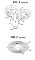
- the tibial component 10 includes a tibial tray 12 and a tibial stem 14 extending outward from and integral with the distal side 16 of the tibial tray 12.
- the stem is hollow and can accept a stem extension (not shown) at its distal end 24.
- the keels 18, 20, 22 serve to help stabilize the implant 10 in the proximal tibia.
- FIGS. 2-5 of the drawings An example of such a system is illustrated in FIGS. 2-5 of the drawings.
- the tibial component 30 of this prior art system also has a tibial tray 32 and an integral stem 34 that can be connected to stem extensions (not shown) at the distal end 38.
- stem extensions not shown
- FIGS. 2-5 An example of such a system is illustrated in FIGS. 2-5 of the drawings.
- the tibial component 30 of this prior art system also has a tibial tray 32 and an integral stem 34 that can be connected to stem extensions (not shown) at the distal end 38.
- stem extensions not shown
- the modular sleeve is shown at 40 in FIGS. 2-4.
- the modular sleeve 40 has a tapered interior bore 42 that in which part of the stem 34 of the tibial component 40 of FIG. 5 is received.
- the tapered interior bore 42 is widest at the proximal end and most narrow at the distal end, corresponding to the shape of the stem 34.
- the proximal surface 44 of the modular sleeve 40 has an overall elliptical shape and is generally flat to fit against the distal surface 36 of the tibial tray 32.
- the modular sleeve has a stepped or terraced outer surface 46. The sleeves help stabilize the implant, particularly in case of bone loss, and distribute load.
- the present invention provides a modular prosthetic implant system that provides the surgeon and patient with the advantages of both a keeled tibial component and a modular sleeve design, increasing the surgeon's options during surgery so that the optimal implant design can be selected for the patient's needs.
- the present invention provides a modular prosthetic tibial sleeve comprising a proximal surface having a generally oval outline with spaced reliefs.
- the sleeve also has a distal end and a terraced outer surface tapering from the proximal surface toward the distal end.
- the sleeve has an interior channel extending from the proximal surface to the distal end.
- the present invention provides a prosthetic knee system comprising a tibial component and a modular sleeve.
- the tibial component comprises a tibial tray, a stem and keels.
- the modular sleeve comprises a proximal surface with spaced reliefs, a distal end, and an interior channel extending from the proximal surface to the distal end.
- the reliefs are sized, shaped and positioned to allow the modular sleeve to be mounted on the tibial component with the stem of the tibial component received in the interior channel of the sleeve and the keels of the tibial component received in the spaced reliefs of the modular sleeve.
- FIGS. 6 to 22 show a prosthetic knee implant system 100 which includes a tibial component 102 and a modular sleeve 104.
- the tibial component 102 and modular sleeve 104 can be provided as components of a prosthetic knee implant system that also includes a femoral component and tibial bearing.
- FIG. 21 An example of a femoral component is illustrated at 103 in FIG. 21 and an example of a tibial bearing insert is illustrated at 105 in FIG. 22. It should be understood that these illustrated components 103, 105 are provided as examples of components that can be used with the tibial component 102 and modular sleeve 104 shown in FIGS. 6-20. The present invention is not limited to the particular femoral and tibial bearing insert components 103, 105 illustrated or the illustrated features of these components unless expressly called for in the claims.
- the tibial component 102 of the illustrated system 100 includes a tibial tray 106 and an integral stem 108 extending distally from the distal side 110 of the tibial tray 106.
- Two keels 112, 114 are integral with and connect the tibial tray 106 and the stem 108.
- the two keels 112, 114 extend outward and toward the posterior side 116 of the tray 106, defining an angle of 130°, as shown at ⁇ in FIG. 9.
- this particular keel configuration is provided by way of example only; the invention is not limited to any particular number or geometric relationship between the keels unless expressly called for in the claims; for example, the tibial component could have three or more keels.
- the illustrated tibial component is symmetrical about a central plane 121 that divides the tibial tray 106 into medial and lateral portions.
- the stem 108 is tapered from a widest dimension at the tibial tray 106 to a most narrow dimension at the distal end 109 of the stem 108.
- the stem has an anterior side 117 and posterior side 119.
- the central stem 108 has a Morse taper.
- the illustrated modular sleeve 104 has a stepped or terraced outer surface 118, tapering with each step from the proximal end 120 to the distal end 122.
- This terraced surface 118 serves the same function as the terraced surface of the prior art modular sleeve: it helps to stabilize the implant in the tibia, particularly in the case of bone loss, and to distribute load in the tibia.
- the invention is not limited to the illustrated configuration unless expressly called for in the claims.
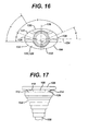
- the modular sleeve 104 of the illustrated embodiment has an overall elliptical outline, with a major axis 124 and a minor axis 126, and a central longitudinal axis 128. It has proximal surface 129 with a posterior-facing edge 130 and an anterior-facing edge 132.
- the major axis 124 defines a posterior portion 131 and an anterior portion 133 of the proximal surface (shown in FIGS. 12 and 16).
- the proximal surface 129 has an overall oval outline in top plan view.
- the modular sleeve 104 of the illustrated embodiment includes two reliefs 134, 136 in the proximal surface 129, generally in the posterior portion 131 between the major axis 124 and the posterior-facing edge 132 of the modular sleeve 104.
- These reliefs 134, 136 are shaped to receive the two keels 112, 114 of the tibial component 110 so that the modular sleeve can be used with the keeled tibial component.
- the two reliefs 134, 136 are shaped to allow some relative rotation between the tibial component 110 and the sleeve 104 when the tibial component 110 and sleeve 104 are assembled.
- FIG. 16 illustrates the angular relationships of various structures of the sleeve 104. In the illustrated embodiment, the angle ⁇ is 56°, ⁇ is 25°, ⁇ is 130° to correspond with the angle ⁇ between the keels 112, 114 as shown in FIG. 9, and ⁇ is 25°. With these angular relationships, the shapes of the keels 112, 114 and reliefs 134, 136 in the illustrated embodiment will allow for about plus or minus 20° relative rotation between these components 104, 110 in assembly.
- the modular sleeve 104 also has an interior channel 140 that extends from the proximal surface 129 to the distal end 122 of the sleeve 104.
- the interior channel 140 is shaped to receive and frictionally interlock with the stem 108 of the tibial component 110 when the sleeve 104 and tibial component 110 are assembled and impacted together.
- the interior channel 140 tapers from a largest diameter at the proximal surface 129 to a smallest diameter at the distal end 122.
- the tapers of the interior channel 140 and stem 108 are Morse tapers. Once the stem 108 and sleeve 104 frictionally interlock, there is no longer any relative rotation or longitudinal movement between the stem 108 and sleeve 104.
- the components of the system of the present invention may be made out of standard materials for such prosthetic implants.
- the modular sleeve may be made out of a titanium alloy or a cobalt chrome alloy
- the tibial component can be made also be made out of a titanium or cobalt chrome alloy.
- the system of the present invention may be provided with the features disclosed in the European patent applications filed with the present application which claim priority from US patent application no. 60/409319, entitled “Universal tibial augment”, and US patent application no. 60/409262, entitled “Duo-fixation prosthetic joints”.
- the surgeon prepares the patient and performs standard surgical techniques to prepare the bone to receive the tibial component 110. For example, the surgeon may progressively ream the intramedullary canal of the tibia to receive the stem 108 and an appropriately sized stem extension (not shown). Trialing may be done in a standard manner. During the procedure, the surgeon determines if the condition of the patient's proximal tibia is suitable for use of the tibial component 110 alone without the sleeve 104.
- the surgeon can implant the tibial component 110 in a standard manner, and the interaction of the keels 112, 114 and the patient's bone tissue should stabilize the tibial component 110 in the bone. If the surgeon determines that there is a cavity defect or inadequate healthy bone tissue in the proximal tibia, the surgeon can prepare the proximal tibia to receive the assembly of the tibial component and the sleeve using standard reamers and broaches. The surgeon can then insert the stem 108 through the channel 140 of the sleeve 104 and move them together until the keels 112, 114 are received in the reliefs 134, 136 of the sleeve.
- the modular assembly of the tibial component 110 and sleeve 104 can then be implanted in a standard manner. Impaction of the assembly 110, 104 should interlock the components 110, 104 together. The surgeon can perform other standard techniques to complete the preparation of the femur.
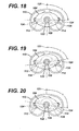
- FIGS. 17-20 The modular assembly of the tibial component 110 and the sleeve 104 is illustrated in FIGS. 17-20.
- the design of the reliefs 134, 136 in the present invention allows for some independent positioning of the sleeve 104 and the tibial component 110, as shown in FIGS. 18-20.
- the surgeon can place the sleeve 104 in an optimal position for stabilizing the implant while also setting the tibial component 110 in the proper position for interaction with the femoral component 103 of the implant system. For example, as shown in FIG.
- the sleeve 104 and be placed on the tibial component such that the keels 112, 114 are substantially centred in the reliefs 134, 136; in this configuration, the angle ⁇ between the central plane 121 of the tibial tray and a plane through the major axis 124 of the sleeve 104 can vary: in FIG. 18, the angle ⁇ is 90°.
- the keels can also be off-centre in the reliefs, as shown in FIGS. 19 and 20: in FIG. 19, the angle ⁇ is 70°; and in FIG. 20 the angle ⁇ is 110°.
- the illustrated embodiment of the invention allows the surgeon to rotate the tibial component and sleeve about the interior channel 140 of the sleeve, with a latitude of ⁇ 20°. It should be understood that these angles are provided as examples only; the present invention is not limited to these angles or to any particular degree of freedom unless expressly called for in the claims.
- the surgeon can interlock the tibial component 102 and the sleeve 104 in this optimal position by impacting the components to frictionally engage the stem 108 and the interior surface of the sleeve 104 that defines the interior channel 140.
- the tibial component 102 and sleeve 104 can be locked in a variety of relative positions, such as the positions illustrated in FIGS. 18 to 20.
- tibial components 110 and sleeves 104 can be provided in a single surgical kit for use by the surgeon.
- tibial component would be used in conjunction with a tibial bearing insert such as that illustrated at 105 in FIG. 22 and with a femoral component such as that illustrated at 103 in FIG. 21.
Landscapes
- Health & Medical Sciences (AREA)
- Orthopedic Medicine & Surgery (AREA)
- Cardiology (AREA)
- Oral & Maxillofacial Surgery (AREA)
- Transplantation (AREA)
- Engineering & Computer Science (AREA)
- Biomedical Technology (AREA)
- Heart & Thoracic Surgery (AREA)
- Vascular Medicine (AREA)
- Life Sciences & Earth Sciences (AREA)
- Animal Behavior & Ethology (AREA)
- General Health & Medical Sciences (AREA)
- Public Health (AREA)
- Veterinary Medicine (AREA)
- Physical Education & Sports Medicine (AREA)
- Prostheses (AREA)
Abstract
Description
Claims (13)
- A prosthetic knee system comprising:wherein the relief is sized, shaped and positioned to allow the modular sleeve to be mounted on the tibial component with the stem of the tibial component received in the interior channel of the sleeve and the keel of the tibial component received in the relief of the modular sleeve.a tibial component comprising a tibial tray, a stem and a keel;a modular sleeve comprising a proximal surface with a relief, a distal end, and an interior channel extending from the proximal surface to the distal end;
- The prosthetic knee system of claim 1 wherein the proximal surface of the sleeve has a generally oval shape with a major axis defining posterior and anterior portions of the proximal surface, and wherein the relief is in the posterior portion of the proximal surface of the sleeve.
- The prosthetic knee system of claim 1 wherein the keel and relief are sized, shaped and positioned to allow relative rotation between the tibial component and the sleeve.
- The prosthetic knee system of claim 3 wherein the keel and relief are sized, shaped and positioned to allow plus or minus twenty degrees of rotation.
- The prosthetic knee system of claim 3 wherein the tibial component has a plurality of spaced keels and the sleeve has a plurality of spaced reliefs in the proximal surface to receive the keels.
- The prosthetic knee system of claim 3 wherein the stem of the tibial component and the interior channel of the modular sleeve are shaped to allow the tibial component and modular sleeve to be frictionally locked together with the tibial component and modular sleeve in a predetermined position.
- The prosthetic knee system of claim 6 wherein the tibial component has a central plane defining medial and lateral portions and the proximal surface of the modular sleeve has a major axis, and wherein the tibial component and modular sleeve are capable of being frictionally locked together in a position wherein the angle between the central plane of the tibial component and the major axis of the proximal surface of the modular sleeve is less than 90°.
- The prosthetic knee system of claim 6 wherein the tibial component has a central plane defining medial and lateral portions and the proximal surface of the modular sleeve has a major axis, and wherein the tibial component and modular sleeve are capable of being frictionally locked together in a position wherein the angle between the central plane of the tibial component and the major axis of the proximal surface of the modular sleeve is 90°.
- The prosthetic knee system of claim 8 wherein the tibial component has a central plane defining medial and lateral portions and the proximal surface of the modular sleeve has a major axis, and wherein the tibial component and modular sleeve are capable of being frictionally locked together in a position wherein the angle between the central plane of the tibial component and the major axis of the proximal surface of the modular sleeve is less than 90°.
- The prosthetic knee system of claim 9 wherein the tibial component has a central plane defining medial and lateral portions and the proximal surface of the modular sleeve has a major axis, and wherein the tibial component and modular sleeve are capable of being frictionally locked together in a position where the angle between the central plane of the tibial component and the major axis of the proximal surface of the modular sleeve is between 70° and 110°.
- A prosthetic knee system comprising:wherein the relief is sized, shaped and positioned to allow the modular sleeve to be mounted on the tibial component with the stem of the tibial component received in the interior channel of the sleeve and the keel of the tibial component received in the relief of the modular sleeve.a femoral component;a tibial component comprising a tibial tray, a stem and a keel;a tibial bearing component;a modular sleeve comprising a proximal surface with a relief, a distal end, and an interior channel extending from the proximal surface to the distal end;
- A modular prosthetic tibial sleeve comprising:a proximal surface having a generally oval outline with spaced reliefs;a distal end;a terraced outer surface tapering from the proximal surface toward the distal end; andan interior channel extending from the proximal surface to the distal end.
- The modular prosthetic tibial sleeve of claim 12 wherein the proximal surface has a posterior edge, an anterior edge and a major axis between the posterior edge and anterior edge defining a posterior portion and an anterior portion, and wherein the reliefs are positioned on the posterior portion of the proximal surface.
Applications Claiming Priority (4)
| Application Number | Priority Date | Filing Date | Title |
|---|---|---|---|
| US40928402P | 2002-09-09 | 2002-09-09 | |
| US409284P | 2002-09-09 | ||
| US10/641,752 US7291174B2 (en) | 2002-09-09 | 2003-08-15 | Prosthetic tibial component with modular sleeve |
| US641752 | 2003-08-15 |
Publications (3)
| Publication Number | Publication Date |
|---|---|
| EP1396240A2 true EP1396240A2 (en) | 2004-03-10 |
| EP1396240A3 EP1396240A3 (en) | 2004-03-31 |
| EP1396240B1 EP1396240B1 (en) | 2008-04-23 |
Family
ID=31720750
Family Applications (1)
| Application Number | Title | Priority Date | Filing Date |
|---|---|---|---|
| EP03255626A Expired - Lifetime EP1396240B1 (en) | 2002-09-09 | 2003-09-09 | Prosthetic tibial component with modular sleeve |
Country Status (5)
| Country | Link |
|---|---|
| US (1) | US7291174B2 (en) |
| EP (1) | EP1396240B1 (en) |
| AT (1) | ATE392868T1 (en) |
| AU (1) | AU2003244596B2 (en) |
| DE (1) | DE60320493T2 (en) |
Cited By (4)
| Publication number | Priority date | Publication date | Assignee | Title |
|---|---|---|---|---|
| WO2012162180A1 (en) * | 2011-05-20 | 2012-11-29 | Zimmer, Inc. | Stabilizing prosthesis support structure |
| WO2016183446A1 (en) * | 2015-05-13 | 2016-11-17 | Smith & Nephew, Inc. | Anatomically shaped augments |
| WO2016183439A1 (en) * | 2015-05-13 | 2016-11-17 | Smith & Nephew, Inc. | Anatomically relieved augments |
| US10413415B2 (en) | 2010-09-10 | 2019-09-17 | Zimmer, Inc. | Motion facilitating tibial components for a knee prosthesis |
Families Citing this family (85)
| Publication number | Priority date | Publication date | Assignee | Title |
|---|---|---|---|---|
| US20020120340A1 (en) | 2001-02-23 | 2002-08-29 | Metzger Robert G. | Knee joint prosthesis |
| US7497874B1 (en) | 2001-02-23 | 2009-03-03 | Biomet Manufacturing Corp. | Knee joint prosthesis |
| US7892288B2 (en) | 2001-08-27 | 2011-02-22 | Zimmer Technology, Inc. | Femoral augments for use with knee joint prosthesis |
| US20030065397A1 (en) | 2001-08-27 | 2003-04-03 | Hanssen Arlen D. | Prosthetic implant support structure |
| US20040162619A1 (en) | 2001-08-27 | 2004-08-19 | Zimmer Technology, Inc. | Tibial augments for use with knee joint prostheses, method of implanting the tibial augment, and associated tools |
| USD684693S1 (en) | 2002-08-22 | 2013-06-18 | Zimmer, Inc. | Prosthetic implant support structure |
| US8328873B2 (en) | 2007-01-10 | 2012-12-11 | Biomet Manufacturing Corp. | Knee joint prosthesis system and method for implantation |
| US8562616B2 (en) | 2007-10-10 | 2013-10-22 | Biomet Manufacturing, Llc | Knee joint prosthesis system and method for implantation |
| US8163028B2 (en) | 2007-01-10 | 2012-04-24 | Biomet Manufacturing Corp. | Knee joint prosthesis system and method for implantation |
| US8157869B2 (en) | 2007-01-10 | 2012-04-17 | Biomet Manufacturing Corp. | Knee joint prosthesis system and method for implantation |
| US8187280B2 (en) | 2007-10-10 | 2012-05-29 | Biomet Manufacturing Corp. | Knee joint prosthesis system and method for implantation |
| DE102007028087B4 (en) | 2007-06-11 | 2014-05-15 | Aesculap Ag | Modular implant part and knee joint prosthesis |
| US8435241B2 (en) * | 2007-12-20 | 2013-05-07 | Depuy Products, Inc. | Keel punch impactor with connection device |
| DE102008014837A1 (en) | 2008-03-07 | 2009-09-10 | Aesculap Ag | Medical implant and knee joint endoprosthesis |
| US20100114323A1 (en) | 2008-10-31 | 2010-05-06 | Depuy Products, Inc. | Knee prosthesis kit with winged sleeves and milling guide |
| US9510949B2 (en) * | 2009-06-26 | 2016-12-06 | The Cleveland Clinic Foundation | Prosthetic joint component with rotation-regulating structure |
| US20110082561A1 (en) * | 2009-10-05 | 2011-04-07 | Perry Forrester | Surgical implant |
| US8932364B2 (en) | 2010-07-14 | 2015-01-13 | Howmedica Osteonics Corp. | Prosthetic knee void filers with splined fixation |
| BR112013001673B1 (en) | 2010-07-24 | 2021-02-09 | Zimmer, Inc | asymmetric tibia components for a knee prosthesis |
| WO2012018563A1 (en) | 2010-07-24 | 2012-02-09 | Zimmer, Inc. | Tibial prosthesis |
| US8535386B2 (en) | 2010-10-21 | 2013-09-17 | Howmedica Osteonics Corp. | Stem with pressfit porous element |
| US8603101B2 (en) | 2010-12-17 | 2013-12-10 | Zimmer, Inc. | Provisional tibial prosthesis system |
| US8926619B2 (en) | 2011-06-30 | 2015-01-06 | Depuy (Ireland) | Method of surgically preparing a tibia for implantation of a prosthetic component |
| US8986390B2 (en) | 2011-06-30 | 2015-03-24 | Depuy (Ireland) | Method of trialing a knee prosthesis |
| US8968412B2 (en) | 2011-06-30 | 2015-03-03 | Depuy (Ireland) | Trialing system for a knee prosthesis and method of use |
| US8939986B2 (en) | 2011-06-30 | 2015-01-27 | Depuy (Ireland) | Surgical instruments for use in surgically preparing a tibia for implantation of a prosthetic component |
| USD666713S1 (en) * | 2011-06-30 | 2012-09-04 | Depuy Products, Inc. | Tibial keel punch |
| US8951301B2 (en) | 2011-06-30 | 2015-02-10 | Depuy (Ireland) | Method of using a trialing system for a knee prosthesis |
| US8852197B2 (en) | 2011-06-30 | 2014-10-07 | Depuy (Ireland) | Surgical instrument assemblies for use in surgically preparing a tibia for implantation of a prosthetic component |
| EP2779950B1 (en) | 2011-11-18 | 2015-12-16 | Zimmer, Inc. | Tibial bearing component for a knee prosthesis with improved articular characteristics |
| CN104093380B (en) | 2011-11-21 | 2016-08-31 | 捷迈有限公司 | Tibial baseplate with asymmetrically placed fixation structures |
| WO2013086340A1 (en) | 2011-12-09 | 2013-06-13 | Howmedica Osteonics Corp. | Surgical reaming instrument for shaping a bone cavity |
| AU2012362279A1 (en) | 2011-12-30 | 2014-07-24 | Howmedica Osteonics Corp. | Systems for preparing bone voids to receive a prosthesis |
| CN104203160B (en) | 2012-01-30 | 2016-05-11 | 捷迈有限公司 | For the asymmetric shin bone part of knee-joint prosthesis |
| US8721733B2 (en) | 2012-05-14 | 2014-05-13 | Depuy (Ireland) | Prosthesis kit with finned sleeve |
| WO2013190573A1 (en) * | 2012-06-20 | 2013-12-27 | Dominions Healthcare Pvt. Ltd. | Knee joint prosthesis |
| US8961612B2 (en) | 2012-08-30 | 2015-02-24 | Biomet Manufacturing, Llc | Knee component having orbital interface boss |
| US20140081410A1 (en) | 2012-09-20 | 2014-03-20 | Jay R. Lieberman | Modular knee prosthesis system with multiple lengths of sleeves sharing a common geometry |
| US9532879B2 (en) | 2012-09-20 | 2017-01-03 | Depuy Ireland Unlimited Company | Femoral knee prosthesis system with augments and multiple lengths of sleeves sharing a common geometry |
| US8998996B2 (en) | 2012-09-20 | 2015-04-07 | Depuy (Ireland) | Knee prosthesis system with standard and distal offset joint line |
| US9320603B2 (en) | 2012-09-20 | 2016-04-26 | Depuy (Ireland) | Surgical instrument system with multiple lengths of broaches sharing a common geometry |
| US9265613B2 (en) | 2012-09-24 | 2016-02-23 | Russell Nevins | Cementless tibial implant |
| US9526513B2 (en) | 2013-03-13 | 2016-12-27 | Howmedica Osteonics Corp. | Void filling joint prosthesis and associated instruments |
| US10596009B2 (en) | 2013-03-15 | 2020-03-24 | Smith & Nephew, Inc. | Knee augment |
| CN103239303A (en) * | 2013-05-27 | 2013-08-14 | 北京市春立正达医疗器械股份有限公司 | Anatomical tibial plateau prosthesis |
| US9925052B2 (en) | 2013-08-30 | 2018-03-27 | Zimmer, Inc. | Method for optimizing implant designs |
| USD748786S1 (en) * | 2013-10-16 | 2016-02-02 | Depuy (Ireland) | Tibial trial component |
| US9861491B2 (en) | 2014-04-30 | 2018-01-09 | Depuy Ireland Unlimited Company | Tibial trial system for a knee prosthesis |
| US9498343B2 (en) * | 2014-07-25 | 2016-11-22 | Russell Nevins | Implant system for knee prosthesis |
| US10149763B2 (en) | 2015-01-12 | 2018-12-11 | Howmedica Osteonics Corp. | Multipurpose void filling prosthesis |
| US9943413B2 (en) | 2015-01-30 | 2018-04-17 | Russell Nevins | Revision stepped tibial implant |
| MX382177B (en) | 2015-07-09 | 2025-03-13 | Link Waldemar Gmbh Co | TIBIAL AUGMENTATION DEVICE AND TOOL. |
| KR102178695B1 (en) * | 2015-07-09 | 2020-11-13 | 발데마르 링크 게엠베하 운트 코.카게 | Joint sleeve reinforcement device |
| US10278827B2 (en) | 2015-09-21 | 2019-05-07 | Zimmer, Inc. | Prosthesis system including tibial bearing component |
| US10195056B2 (en) | 2015-10-19 | 2019-02-05 | Depuy Ireland Unlimited Company | Method for preparing a patient's tibia to receive an implant |
| US10537445B2 (en) | 2015-10-19 | 2020-01-21 | Depuy Ireland Unlimited Company | Surgical instruments for preparing a patient's tibia to receive an implant |
| CN110191691B (en) | 2017-01-20 | 2022-03-22 | 拜欧米特制造有限责任公司 | Modular expansion component |
| ES3025978T3 (en) | 2017-03-10 | 2025-06-10 | Zimmer Inc | Tibial prosthesis with tibial bearing component securing feature |
| CN110636818B (en) | 2017-05-12 | 2021-06-04 | 捷迈有限公司 | Femoral prosthesis with size augmentation and size reduction capabilities |
| US10987225B2 (en) * | 2017-08-04 | 2021-04-27 | Zimmer, Inc. | Systems and methods for attaching sleeve or cone in prosthetic implant having a stem |
| WO2019075066A1 (en) | 2017-10-11 | 2019-04-18 | Zimmer, Inc. | Impaction cradle |
| JP7125480B2 (en) | 2017-10-13 | 2022-08-24 | ジンマー,インコーポレイティド | Knee arthroplasty method and instrument |
| US10603054B2 (en) | 2017-10-31 | 2020-03-31 | Sicage Llc | Parallel guide for surgical implants |
| USD847336S1 (en) | 2017-10-31 | 2019-04-30 | Sicage Llc | Parallel surgical guide spacer |
| USD850616S1 (en) | 2017-10-31 | 2019-06-04 | Sicage Llc | Parallel surgical guide spacer |
| US11426282B2 (en) | 2017-11-16 | 2022-08-30 | Zimmer, Inc. | Implants for adding joint inclination to a knee arthroplasty |
| US10610365B2 (en) * | 2017-12-23 | 2020-04-07 | Onkos Surgical, Inc. | Implant with ability to capture extravasating fixation medium |
| US10835380B2 (en) | 2018-04-30 | 2020-11-17 | Zimmer, Inc. | Posterior stabilized prosthesis system |
| CA3064394A1 (en) * | 2018-12-07 | 2020-06-07 | Smed-Ta/Td, Llc | Patellofemoral implant with porous ingrowth material and method of manufacturing the same |
| US11565021B1 (en) | 2019-08-12 | 2023-01-31 | Ortho Development Corporation | Composite structure porous implant for replacing bone stock |
| USD901014S1 (en) | 2019-08-12 | 2020-11-03 | Ortho Development Corporation | Porous implant |
| USD901013S1 (en) | 2019-08-12 | 2020-11-03 | Ortho Development Corporation | Porous implant |
| USD901012S1 (en) | 2019-08-12 | 2020-11-03 | Ortho Development Corporation | Porous implant |
| US11498124B1 (en) | 2019-11-25 | 2022-11-15 | Ortho Development Corporation | Method for sintering porous structures from powder using additive manufacturing |
| US12434302B2 (en) | 2019-11-25 | 2025-10-07 | Ortho Development Corporation | Method for manufacturing porous structures using additive manufacturing |
| US11660199B2 (en) | 2020-01-29 | 2023-05-30 | Encore Medical, L.P. | Modular knee augment cones |
| JP7699616B2 (en) * | 2020-07-06 | 2025-06-27 | リマコーポレート・ソチエタ・ペル・アチオニ | Reinforcing elements for knee prostheses |
| IT202000016288A1 (en) * | 2020-07-06 | 2022-01-06 | Limacorporate Spa | AUGMENTATION ELEMENT FOR PROSTHESIS, IN PARTICULAR FOR KNEE PROSTHESIS |
| US11478260B2 (en) | 2020-07-17 | 2022-10-25 | Asfora Ip, Llc | Parallel guide for access needle |
| US12115084B2 (en) | 2021-12-21 | 2024-10-15 | Depuy Ireland Unlimited Company | Method of installing a knee cone augment in an orthopaedic surgical procedure |
| US12478477B2 (en) | 2021-12-21 | 2025-11-25 | Depuy Ireland Unlimited Company | Modular tibial cone augments and method of surgically using the same |
| US12369930B2 (en) | 2022-06-20 | 2025-07-29 | Zimmer, Inc. | Systems for guided reaming of complex shapes |
| US20240033065A1 (en) * | 2022-07-30 | 2024-02-01 | Optimotion Implants LLC | Adjustable arthroplasty devices, systems, and methods |
| US20240033089A1 (en) * | 2022-07-30 | 2024-02-01 | Optimotion Implants LLC | Adjustable arthroplasty devices, systems, and methods |
| CN116115392B (en) * | 2023-02-01 | 2024-08-13 | 中国人民解放军总医院第一医学中心 | A universal anatomical stepped porous metal cone for the tibial side |
Family Cites Families (9)
| Publication number | Priority date | Publication date | Assignee | Title |
|---|---|---|---|---|
| US4634444A (en) | 1984-02-09 | 1987-01-06 | Joint Medical Products Corporation | Semi-constrained artificial joint |
| US5011496A (en) | 1988-02-02 | 1991-04-30 | Joint Medical Products Corporation | Prosthetic joint |
| US4888021A (en) | 1988-02-02 | 1989-12-19 | Joint Medical Products Corporation | Knee and patellar prosthesis |
| US4944757A (en) | 1988-11-07 | 1990-07-31 | Martinez David M | Modulator knee prosthesis system |
| US5152797A (en) | 1991-10-25 | 1992-10-06 | Johnson & Johnson Orthopaedics, Inc. | Modular prosthesis |
| US5282866A (en) | 1992-02-12 | 1994-02-01 | Osteonics Corp. | Prosthetic knee tibial component with axially ribbed keel and apparatus for effecting implant |
| US5480445A (en) | 1994-06-09 | 1996-01-02 | Intermedics Orthopedics, Inc. | Interlocking tibial prosthesis |
| US6053945A (en) * | 1997-09-25 | 2000-04-25 | Johnson & Johnson Professional, Inc. | Joint prosthesis having controlled rotation |
| DE69918894T2 (en) | 1998-05-13 | 2005-08-11 | Depuy Products, Inc., Warsaw | Tibial platform with adjustable shaft |
-
2003
- 2003-08-15 US US10/641,752 patent/US7291174B2/en not_active Expired - Lifetime
- 2003-09-08 AU AU2003244596A patent/AU2003244596B2/en not_active Expired
- 2003-09-09 AT AT03255626T patent/ATE392868T1/en not_active IP Right Cessation
- 2003-09-09 DE DE60320493T patent/DE60320493T2/en not_active Expired - Lifetime
- 2003-09-09 EP EP03255626A patent/EP1396240B1/en not_active Expired - Lifetime
Cited By (14)
| Publication number | Priority date | Publication date | Assignee | Title |
|---|---|---|---|---|
| US10413415B2 (en) | 2010-09-10 | 2019-09-17 | Zimmer, Inc. | Motion facilitating tibial components for a knee prosthesis |
| US9517138B2 (en) | 2011-05-20 | 2016-12-13 | Zimmer, Inc. | Stabilizing prosthesis support structure |
| US8900317B2 (en) | 2011-05-20 | 2014-12-02 | Zimmer, Inc. | Stabilizing prosthesis support structure |
| AU2012258998B2 (en) * | 2011-05-20 | 2016-05-05 | Zimmer, Inc. | Stabilizing prosthesis support structure |
| WO2012162180A1 (en) * | 2011-05-20 | 2012-11-29 | Zimmer, Inc. | Stabilizing prosthesis support structure |
| JP2018518239A (en) * | 2015-05-13 | 2018-07-12 | スミス アンド ネフュー インコーポレイテッド | Anatomically relaxed aid |
| WO2016183439A1 (en) * | 2015-05-13 | 2016-11-17 | Smith & Nephew, Inc. | Anatomically relieved augments |
| WO2016183446A1 (en) * | 2015-05-13 | 2016-11-17 | Smith & Nephew, Inc. | Anatomically shaped augments |
| US10912649B2 (en) | 2015-05-13 | 2021-02-09 | Smith & Nephew, Inc. | Anatomically shaped augments |
| AU2016260418B2 (en) * | 2015-05-13 | 2021-04-01 | Smith & Nephew, Inc. | Anatomically relieved augments |
| US11116637B2 (en) | 2015-05-13 | 2021-09-14 | Smith & Nephew, Inc. | Anatomically relieved augments |
| US12048627B2 (en) | 2015-05-13 | 2024-07-30 | Smith & Nephew, Inc. | Anatomically relieved augments |
| EP3294224B1 (en) | 2015-05-13 | 2024-10-23 | Smith & Nephew, Inc. | Anatomically shaped augments |
| US12186194B2 (en) | 2015-05-13 | 2025-01-07 | Smith & Nephew, Inc. | Anatomically shaped augments |
Also Published As
| Publication number | Publication date |
|---|---|
| EP1396240A3 (en) | 2004-03-31 |
| AU2003244596A1 (en) | 2004-03-25 |
| ATE392868T1 (en) | 2008-05-15 |
| DE60320493D1 (en) | 2008-06-05 |
| AU2003244596B2 (en) | 2009-05-28 |
| EP1396240B1 (en) | 2008-04-23 |
| US20040049286A1 (en) | 2004-03-11 |
| DE60320493T2 (en) | 2009-07-09 |
| US7291174B2 (en) | 2007-11-06 |
Similar Documents
| Publication | Publication Date | Title |
|---|---|---|
| EP1396240B1 (en) | Prosthetic tibial component with modular sleeve | |
| US11648127B2 (en) | Method and system including sleeves and broaches for surgically preparing the patient's bone | |
| AU2018204287B2 (en) | Femoral knee prosthesis system with augments and multiple lengths of sleeves sharing common geometry | |
| EP1398006A2 (en) | Duo-fixation prosthetic joints | |
| EP1623686B1 (en) | Modular orthopaedic implant system | |
| EP2664301B1 (en) | Prosthesis kit with finned sleeve | |
| EP2710979B1 (en) | Modular knee prosthesis system | |
| EP1430856A1 (en) | Modular prosthetic knee implant system comprising femoral stem augment | |
| AU2018204289B2 (en) | Modular knee prosthesis with multiple lengths of sleeves sharing a common geometry | |
| US20070050039A1 (en) | Orthopaedic implant, stem and associated method | |
| EP2682073B1 (en) | Knee prosthesis system with side-mounted augments |
Legal Events
| Date | Code | Title | Description |
|---|---|---|---|
| PUAI | Public reference made under article 153(3) epc to a published international application that has entered the european phase |
Free format text: ORIGINAL CODE: 0009012 |
|
| PUAL | Search report despatched |
Free format text: ORIGINAL CODE: 0009013 |
|
| AK | Designated contracting states |
Kind code of ref document: A2 Designated state(s): AT BE BG CH CY CZ DE DK EE ES FI FR GB GR HU IE IT LI LU MC NL PT RO SE SI SK TR |
|
| AX | Request for extension of the european patent |
Extension state: AL LT LV MK |
|
| AK | Designated contracting states |
Kind code of ref document: A3 Designated state(s): AT BE BG CH CY CZ DE DK EE ES FI FR GB GR HU IE IT LI LU MC NL PT RO SE SI SK TR |
|
| AX | Request for extension of the european patent |
Extension state: AL LT LV MK |
|
| 17P | Request for examination filed |
Effective date: 20040903 |
|
| AKX | Designation fees paid |
Designated state(s): AT BE BG CH CY CZ DE DK EE ES FI FR GB GR HU IE IT LI LU MC NL PT RO SE SI SK TR |
|
| GRAP | Despatch of communication of intention to grant a patent |
Free format text: ORIGINAL CODE: EPIDOSNIGR1 |
|
| GRAS | Grant fee paid |
Free format text: ORIGINAL CODE: EPIDOSNIGR3 |
|
| GRAA | (expected) grant |
Free format text: ORIGINAL CODE: 0009210 |
|
| AK | Designated contracting states |
Kind code of ref document: B1 Designated state(s): AT BE BG CH CY CZ DE DK EE ES FI FR GB GR HU IE IT LI LU MC NL PT RO SE SI SK TR |
|
| REG | Reference to a national code |
Ref country code: GB Ref legal event code: FG4D |
|
| REG | Reference to a national code |
Ref country code: CH Ref legal event code: EP |
|
| REG | Reference to a national code |
Ref country code: CH Ref legal event code: NV Representative=s name: E. BLUM & CO. AG PATENT- UND MARKENANWAELTE VSP |
|
| REF | Corresponds to: |
Ref document number: 60320493 Country of ref document: DE Date of ref document: 20080605 Kind code of ref document: P |
|
| REG | Reference to a national code |
Ref country code: IE Ref legal event code: FG4D Free format text: LANGUAGE OF EP DOCUMENT: FRENCH |
|
| PG25 | Lapsed in a contracting state [announced via postgrant information from national office to epo] |
Ref country code: SI Free format text: LAPSE BECAUSE OF FAILURE TO SUBMIT A TRANSLATION OF THE DESCRIPTION OR TO PAY THE FEE WITHIN THE PRESCRIBED TIME-LIMIT Effective date: 20080423 |
|
| NLV1 | Nl: lapsed or annulled due to failure to fulfill the requirements of art. 29p and 29m of the patents act | ||
| PG25 | Lapsed in a contracting state [announced via postgrant information from national office to epo] |
Ref country code: ES Free format text: LAPSE BECAUSE OF FAILURE TO SUBMIT A TRANSLATION OF THE DESCRIPTION OR TO PAY THE FEE WITHIN THE PRESCRIBED TIME-LIMIT Effective date: 20080803 Ref country code: NL Free format text: LAPSE BECAUSE OF FAILURE TO SUBMIT A TRANSLATION OF THE DESCRIPTION OR TO PAY THE FEE WITHIN THE PRESCRIBED TIME-LIMIT Effective date: 20080423 Ref country code: FI Free format text: LAPSE BECAUSE OF FAILURE TO SUBMIT A TRANSLATION OF THE DESCRIPTION OR TO PAY THE FEE WITHIN THE PRESCRIBED TIME-LIMIT Effective date: 20080423 Ref country code: BG Free format text: LAPSE BECAUSE OF FAILURE TO SUBMIT A TRANSLATION OF THE DESCRIPTION OR TO PAY THE FEE WITHIN THE PRESCRIBED TIME-LIMIT Effective date: 20080723 Ref country code: PT Free format text: LAPSE BECAUSE OF FAILURE TO SUBMIT A TRANSLATION OF THE DESCRIPTION OR TO PAY THE FEE WITHIN THE PRESCRIBED TIME-LIMIT Effective date: 20080923 |
|
| PG25 | Lapsed in a contracting state [announced via postgrant information from national office to epo] |
Ref country code: AT Free format text: LAPSE BECAUSE OF FAILURE TO SUBMIT A TRANSLATION OF THE DESCRIPTION OR TO PAY THE FEE WITHIN THE PRESCRIBED TIME-LIMIT Effective date: 20080423 |
|
| ET | Fr: translation filed | ||
| PG25 | Lapsed in a contracting state [announced via postgrant information from national office to epo] |
Ref country code: SE Free format text: LAPSE BECAUSE OF FAILURE TO SUBMIT A TRANSLATION OF THE DESCRIPTION OR TO PAY THE FEE WITHIN THE PRESCRIBED TIME-LIMIT Effective date: 20080723 Ref country code: DK Free format text: LAPSE BECAUSE OF FAILURE TO SUBMIT A TRANSLATION OF THE DESCRIPTION OR TO PAY THE FEE WITHIN THE PRESCRIBED TIME-LIMIT Effective date: 20080423 Ref country code: CZ Free format text: LAPSE BECAUSE OF FAILURE TO SUBMIT A TRANSLATION OF THE DESCRIPTION OR TO PAY THE FEE WITHIN THE PRESCRIBED TIME-LIMIT Effective date: 20080423 |
|
| PG25 | Lapsed in a contracting state [announced via postgrant information from national office to epo] |
Ref country code: SK Free format text: LAPSE BECAUSE OF FAILURE TO SUBMIT A TRANSLATION OF THE DESCRIPTION OR TO PAY THE FEE WITHIN THE PRESCRIBED TIME-LIMIT Effective date: 20080423 Ref country code: BE Free format text: LAPSE BECAUSE OF FAILURE TO SUBMIT A TRANSLATION OF THE DESCRIPTION OR TO PAY THE FEE WITHIN THE PRESCRIBED TIME-LIMIT Effective date: 20080423 Ref country code: RO Free format text: LAPSE BECAUSE OF FAILURE TO SUBMIT A TRANSLATION OF THE DESCRIPTION OR TO PAY THE FEE WITHIN THE PRESCRIBED TIME-LIMIT Effective date: 20080423 |
|
| PLBE | No opposition filed within time limit |
Free format text: ORIGINAL CODE: 0009261 |
|
| STAA | Information on the status of an ep patent application or granted ep patent |
Free format text: STATUS: NO OPPOSITION FILED WITHIN TIME LIMIT |
|
| 26N | No opposition filed |
Effective date: 20090126 |
|
| PG25 | Lapsed in a contracting state [announced via postgrant information from national office to epo] |
Ref country code: MC Free format text: LAPSE BECAUSE OF NON-PAYMENT OF DUE FEES Effective date: 20080930 Ref country code: EE Free format text: LAPSE BECAUSE OF FAILURE TO SUBMIT A TRANSLATION OF THE DESCRIPTION OR TO PAY THE FEE WITHIN THE PRESCRIBED TIME-LIMIT Effective date: 20080423 |
|
| PG25 | Lapsed in a contracting state [announced via postgrant information from national office to epo] |
Ref country code: LU Free format text: LAPSE BECAUSE OF NON-PAYMENT OF DUE FEES Effective date: 20080909 Ref country code: HU Free format text: LAPSE BECAUSE OF FAILURE TO SUBMIT A TRANSLATION OF THE DESCRIPTION OR TO PAY THE FEE WITHIN THE PRESCRIBED TIME-LIMIT Effective date: 20081024 Ref country code: CY Free format text: LAPSE BECAUSE OF FAILURE TO SUBMIT A TRANSLATION OF THE DESCRIPTION OR TO PAY THE FEE WITHIN THE PRESCRIBED TIME-LIMIT Effective date: 20080423 |
|
| PG25 | Lapsed in a contracting state [announced via postgrant information from national office to epo] |
Ref country code: TR Free format text: LAPSE BECAUSE OF FAILURE TO SUBMIT A TRANSLATION OF THE DESCRIPTION OR TO PAY THE FEE WITHIN THE PRESCRIBED TIME-LIMIT Effective date: 20080423 |
|
| PG25 | Lapsed in a contracting state [announced via postgrant information from national office to epo] |
Ref country code: GR Free format text: LAPSE BECAUSE OF FAILURE TO SUBMIT A TRANSLATION OF THE DESCRIPTION OR TO PAY THE FEE WITHIN THE PRESCRIBED TIME-LIMIT Effective date: 20080724 |
|
| REG | Reference to a national code |
Ref country code: FR Ref legal event code: PLFP Year of fee payment: 14 |
|
| REG | Reference to a national code |
Ref country code: FR Ref legal event code: PLFP Year of fee payment: 15 |
|
| REG | Reference to a national code |
Ref country code: FR Ref legal event code: PLFP Year of fee payment: 16 |
|
| PGFP | Annual fee paid to national office [announced via postgrant information from national office to epo] |
Ref country code: IT Payment date: 20220811 Year of fee payment: 20 Ref country code: IE Payment date: 20220809 Year of fee payment: 20 Ref country code: GB Payment date: 20220728 Year of fee payment: 20 Ref country code: DE Payment date: 20220609 Year of fee payment: 20 |
|
| PGFP | Annual fee paid to national office [announced via postgrant information from national office to epo] |
Ref country code: FR Payment date: 20220808 Year of fee payment: 20 |
|
| PGFP | Annual fee paid to national office [announced via postgrant information from national office to epo] |
Ref country code: CH Payment date: 20221001 Year of fee payment: 20 |
|
| REG | Reference to a national code |
Ref country code: DE Ref legal event code: R071 Ref document number: 60320493 Country of ref document: DE |
|
| REG | Reference to a national code |
Ref country code: CH Ref legal event code: PL |
|
| REG | Reference to a national code |
Ref country code: GB Ref legal event code: PE20 Expiry date: 20230908 |
|
| REG | Reference to a national code |
Ref country code: IE Ref legal event code: MK9A |
|
| PG25 | Lapsed in a contracting state [announced via postgrant information from national office to epo] |
Ref country code: GB Free format text: LAPSE BECAUSE OF EXPIRATION OF PROTECTION Effective date: 20230908 |
|
| PG25 | Lapsed in a contracting state [announced via postgrant information from national office to epo] |
Ref country code: IE Free format text: LAPSE BECAUSE OF EXPIRATION OF PROTECTION Effective date: 20230909 |