EP1396128B1 - Adaptive symbol mapping in mobile system - Google Patents
Adaptive symbol mapping in mobile system Download PDFInfo
- Publication number
- EP1396128B1 EP1396128B1 EP02722315A EP02722315A EP1396128B1 EP 1396128 B1 EP1396128 B1 EP 1396128B1 EP 02722315 A EP02722315 A EP 02722315A EP 02722315 A EP02722315 A EP 02722315A EP 1396128 B1 EP1396128 B1 EP 1396128B1
- Authority
- EP
- European Patent Office
- Prior art keywords
- channel
- transmitter
- bit
- receiver
- status
- Prior art date
- Legal status (The legal status is an assumption and is not a legal conclusion. Google has not performed a legal analysis and makes no representation as to the accuracy of the status listed.)
- Expired - Lifetime
Links
Images


Classifications
-
- H—ELECTRICITY
- H04—ELECTRIC COMMUNICATION TECHNIQUE
- H04L—TRANSMISSION OF DIGITAL INFORMATION, e.g. TELEGRAPHIC COMMUNICATION
- H04L1/00—Arrangements for detecting or preventing errors in the information received
- H04L1/0001—Systems modifying transmission characteristics according to link quality, e.g. power backoff
- H04L1/0023—Systems modifying transmission characteristics according to link quality, e.g. power backoff characterised by the signalling
-
- H—ELECTRICITY
- H04—ELECTRIC COMMUNICATION TECHNIQUE
- H04B—TRANSMISSION
- H04B7/00—Radio transmission systems, i.e. using radiation field
- H04B7/02—Diversity systems; Multi-antenna system, i.e. transmission or reception using multiple antennas
- H04B7/04—Diversity systems; Multi-antenna system, i.e. transmission or reception using multiple antennas using two or more spaced independent antennas
- H04B7/06—Diversity systems; Multi-antenna system, i.e. transmission or reception using multiple antennas using two or more spaced independent antennas at the transmitting station
- H04B7/0613—Diversity systems; Multi-antenna system, i.e. transmission or reception using multiple antennas using two or more spaced independent antennas at the transmitting station using simultaneous transmission
- H04B7/0615—Diversity systems; Multi-antenna system, i.e. transmission or reception using multiple antennas using two or more spaced independent antennas at the transmitting station using simultaneous transmission of weighted versions of same signal
-
- H—ELECTRICITY
- H04—ELECTRIC COMMUNICATION TECHNIQUE
- H04L—TRANSMISSION OF DIGITAL INFORMATION, e.g. TELEGRAPHIC COMMUNICATION
- H04L1/00—Arrangements for detecting or preventing errors in the information received
- H04L1/0001—Systems modifying transmission characteristics according to link quality, e.g. power backoff
- H04L1/0002—Systems modifying transmission characteristics according to link quality, e.g. power backoff by adapting the transmission rate
- H04L1/0003—Systems modifying transmission characteristics according to link quality, e.g. power backoff by adapting the transmission rate by switching between different modulation schemes
Definitions
- the invention is applied in mobile systems, particularly systems where information is transmitted between a transmitter and a receiver via at least two transmitting antennas.
- a mobile system In a mobile system, several transmitting antennas are employed to transmit user information in the downlink direction. In the uplink direction the use of several antennas will probably become relevant with the new media terminals.
- Use of a plurality of transmit antenna branches e.g. in a mobile system base station provides diversity gains over the radio connection. Diversity gains are obtained e.g. by means of coherent signal combination and more effective prevention of fading.
- the values a signal obtains over the radio connection are modelled by means of complex numbers, where the absolute value or module of the complex number represents signal amplitude and the polar angle or argument of the complex number represents signal phase.
- the signals transmitted via different antennas are summed in the combined signal propagating over the radio path, the complex values of the signal thus corresponding to the sums of the values obtained by the signals transmitted via different antennas.
- the set of values the combined signal has obtained in the complex plane is referred to as a combined constellation.
- a combined constellation is utilized in the receiver for deducing, from the complex value of the combined signal, the signals transmitted from different antenna branches of the transmitter and combined over the radio path to provide the received complex value.
- the received complex value does not fully correspond to any constellation point, and the receiver must therefore make a decision for example on the basis of the constellation point that is closest to the received complex value.
- the combined constellation is also continuously altered since the transmission channels change e.g. due to different propagation paths of the signals.
- Transmission scheme using fading-resistant constellations discloses a scheme combining space diversity and multidimensional constellations, in order to achieve efficient transmission over slow fading channels. The idea is to map information bits to points of a N-dimensional signal constellation and project these points on certain sub-spaces.
- EP 0998 045 discloses a tranmission method for transmission of a multilevel modulated signal.
- the soft output information of a channel decoder is fed back and utilised by a soft demapping device in order to improve the decoding result by further iterative decoding steps.
- bit-to-symbol mapping remains constant during the connection, i.e. mapping of bits to symbols is independent of the channel status. Since the bit-to-symbol mapping is fixed and radio channel statuses keep changing, the likelihood of erroneous bit decisions made by the receiver increases, thus reducing the accuracy of identification of the transmitted information in the receiver.
- An objective of the invention is to provide an improved method and equipment implementing the method for making correct bit decisions in the receiver. This is achieved by a method according to claim 1 and by apparatus according to claims 12 and 21.
- the invention can be applied in digital radio systems, such as mobile systems.
- the arrangement according to the invention which relates to transmission of information between the transmitter and the receiver, is not restricted to the data transmission direction used, but it can be applied to both uplink and downlink transmission.
- a radio system base station and a terminal equipment operating in the network area can both operate as a transmitter and a receiver.
- the only restriction is that the transmitter must transmit via at least two transmitting antennas.
- information bits to be transmitted by the transmitter are mapped by means of adaptive bit-to-symbol mapping to channel symbols to be transmitted on a transmission channel.
- Adaptivity means herein that the bit-to-symbol mapping and the combined constellation related thereto are altered with the changing radio channel status. A change in the radio channel status is detected by means of measurements performed on the channel.
- bit decisions are carried out on the basis of the values of the received combined signal and the combined constellation used.
- the radio channel changes i.e. the transmission channel transmitted via an antenna changes
- the values of the combined constellation must be updated.
- a combined constellation is formed by summing up all the possible combinations of the channel symbols to be transmitted via different transmitting antennas, the symbols being multiplied by channel coefficients corresponding to the transmission channels.
- the mapping of bits to channel symbols utilizes channel-dependent bit-to-symbol mapping.
- the mapping and the resulting combined constellation are selected from a predetermined set of constellations known to the transmitter and the receiver.
- Radio channel status can be determined by several methods.
- the status is preferably determined by means of channel coefficients, each of which corresponds to a particular transmission channel or antenna.
- a channel coefficient represents the amplitude and phase of the signal transmitted on the transmission channel at one or more instants. Therefore the invention is not restricted to the channel model used, but it can be applied in connection with channel models of one or more taps.
- the radio channel status or channel parameter can also be given in the form of a phase difference or amplitude difference between antennas.
- the radio channel status is determined in the receiver, which forms an estimate of the channel status by means of the received signal, and signals the estimate to the transmitter.
- both the transmitter and the receiver form an estimate of the transmission channel. This embodiment is applicable for example in radio systems based on time division duplex (TDD).
- TDD time division duplex
- only the transmitter measures the channel, and if needed, it signals channel-related information to the receiver.
- Channel-related information is only signalled if necessary, i.e. for example when only the receiver measures the channel and the channel status has changed to such an extent that the bit-to-symbol mapping scheme has to be updated to correspond to the channel status.
- a change in the channel status can be estimated by setting a threshold value for a change of the coefficient, exceeding of the threshold value resulting in a changing bit-to-symbol mapping scheme.
- the bit-to-symbol mapping scheme and the related combined constellation can also be updated for example periodically.
- bit-to-symbol mapping and the related mapping of information bits to binary indices preferably employ such a mapping scheme that results in the combined constellation in a minimum Hamming distance between adjacent constellation points.
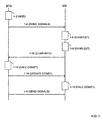
- Figure 1 shows a preferred embodiment of the method according to the invention.
- the figure shows signalling between a base station BTS and a mobile station MS and the operations carried out in these network parts.
- the first step 1-2 of the method comprises downlink transmission of information, such as user or control information.
- Information bits are converted into channel symbols according to the current bit-to-symbol mapping scheme for transmission via two or more transmitting antennas.
- the information to be transmitted can be divided in several manners to the antennas. For example in the case of two antennas, the information can be split in two such that two bits are transmitted via the first antenna, two bits via the second antenna, two bits again via the first antenna and so forth. It is also possible to transmit all the information via both antennas, in which case the information is transmitted via the second antenna in an interleaved, delayed or coded form.
- Method step 1-4 of Figure 1 comprises transmitting information from the transmitter BTS via at least two antennas.
- the pieces of information transmitted via different antennas are summed up over the radio path into a combined signal received in the receiver MS.
- the receiver MS forms channel parameters from the radio channel, i.e. estimates of the channels that were used to transmit the information.
- the transmissions sent via the antennas are separated and channel coefficients based on e.g. a one-tap channel model are formed from the channels. It is simultaneously estimated whether the channel parameters have changed to such an extent that the constellation point system in use should be updated.
- the receiver MS decomposes the received information by forming estimates of the transmitted symbols. The estimates are formed based on the constellation point system, which includes possible values of the combined signal that are used in an optimum receiver for selecting the constellation point closest to the value of the received signal.
- Method step 1-10 describes transmission of a channel parameter from the receiver to the transmitter.
- a channel parameter can be transmitted e.g. on a control channel in a particular field once during a transmission frame, for instance.
- the channel parameter value can comprise channel information in various forms, such as the value of the channel coefficient, exceeding of the threshold value for the channel coefficient, or a number representing the antenna-specific bit-to-symbol mapping scheme to be used next.
- the transmitter utilizes the information received in step 1-10 to estimate whether the constellation point system should be updated. As an example, it is shown in method step 1-12 that the combined constellation is recalculated and the bit-to-symbol mapping scheme to be used is also reformed.
- Figures 2A , 3A and 3B refer to a prior art arrangement and Figures 2B, 2C , 3C and 3D to an arrangement according to the invention.
- the binary word to be transmitted is [0111] and it is divided between the transmitting antennas such that the first antenna transmits binary word [01] and the second antenna transmits binary word [11].
- the transmission of the aforementioned binary word is described by way of an example at two instants with different channel coefficients of the transmission channels.
- the prior art arrangement utilizes a fixed modulation mapping scheme according to the QPSK modulation method as shown in Figure 2A in both transmitting antennas at each instant.
- Bit combination 00 thus corresponds to complex channel symbol (1+0i)
- bit combination 01 corresponds to symbol (0+1i)
- combination 10 corresponds to symbol (-1+0i)
- combination 11 corresponds to symbol (0-1i).
- the arrangement according to the invention in turn utilizes, at the first instant, the mapping scheme shown in Figure 2B .
- the constellation used by the first transmitting antenna is shown on the left in Figure 2B and the modulation constellation used by the second transmitting antenna is shown on the right.
- Figure 2C in turn shows the modulation constellations used at the second instant in the bit-to-symbol mapping scheme of the arrangement according to the invention, the constellation of the first antenna being shown on the left and the constellation of the second antenna on the right.
- the combined constellation used by the receiver for bit decisions can be formed by summing up the product of c 1 and the QPSK modulation points and the product of c 2 and the QPSK modulation points.
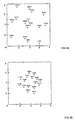
- Examine first Figure 3A which shows the constellation point system formed with the aforementioned channel coefficients.
- the values of the constellation points are shown in Table 1 in a situation where the first two bits of a 4-bit information section are transmitted via the first antenna and the last two bits via the second antenna.
- Table 1 Calculation of constellation points Binary index Calculation of signal value Signal value 0 (0000) (1.4+1.1i)(1+0i)+(-2.0-0.9i)(1+0i) -0.6+0.2i 1 (0001) c 1 (1+0i)+c 2 (0+1i) -2.3-0.9i 2 (0010) c 1 (1+0i)+c 2 (-1+0i) 3.4+2i ... ... ... 7 (0111) c 1 (0+1i)+c 2 (1+0i) -2.0+3.4i ... ... ... ...
- Figure 2A shows two different bit values in the complex plane.
- Binary word [0111] examined in this example thus corresponds to value (-2.0+3.4i) in the complex plane, which is a signal received by the receiver.
- the receiver makes decisions about the value of the received signal on the basis of the combined constellation shown in Figure 2A .
- Figure 3A clearly shows that there is a great likelihood of bit error decisions in the receiver. For example the points corresponding to binary words [0100] and [1011] are situated adjacent to one another in the complex plane. An erroneous decision with respect to these binary words would result in a maximum error of four bits.
- the transmitter utilizes the antenna-specific mapping schemes shown in Figure 2B and at the second instant the mapping schemes shown in Figure 2C .
- Suitable rotation of the modulation constellation thus provides a bit conversion resulting in the optimum reception constellation for the channel symbols shown in Figures 3C and 3D .
- the transmitter and the receiver must be aware of the measured channel parameters and the mapping scheme to be used, and the coordination of these matters will be described below in connection with an arrangement illustrating the invention.
- the order of the combined constellation shown in Figures 3C and 3D is only illustrated by way of an example, and the arrangement according to the invention is not restricted to the above description, nor is it naturally restricted to the modulation method used or the manner of dividing the information to be transmitted to the transmitting antennas. The invention will be described below with respect to the aforementioned arrangement and with reference to Figures 4 to 7 .
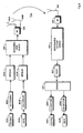
- FIG. 4 shows generally the structure of the UMTS.
- the main elements of the system are a core network CN, a UMTS terrestrial radio access network UTRAN and a user equipment UE, which has been referred to as a mobile station MS in Figure 1 .
- the interface between the CN and the UTRAN is referred to as an lu interface, and the air interface between the UTRAN and the UE is referred to as a Uu interface.
- the functionality related to a radio connection to the UE is carried out in the UTRAN.
- the CN in turn manages routing and connections to systems outside the UMTS, such as a public switched telephone network PSTN and the Internet.
- the user equipment consists of two parts: a mobile equipment ME used as a radio terminal responsible for communication over the Uu interface, and a UMTS subscriber identity module USIM that is a smart card containing data required for user identification and authentication.
- the UTRAN comprises one or more radio network subsystems RNS, each of which in turn consists of at least one radio network controller RNC and nodes B or base stations denoted by BTS in Figure 1 .
- the primary function of node B is to manage the air interface to the UE and the related processing, such as channel coding, interleaving, power control and spreading of user signals.
- the RNC that controls node B in turn manages the UTRAN radio resources, the loading of the cells C of the RNC and the functionality related to allocation of new spreading codes in the cells.
- the core network comprises a gateway MSC GMSC providing access to external networks, a home location register HLR, a mobile services switching centre MSC, a visitor location register VLR, and a serving GPRS (General Packet Radio Service) support node SGSN providing packet switched connections with routing services.
- the Uu radio interface is a three-layer protocol stack comprising a physical layer L1, a data link layer L2 and a network layer L3.
- the data link layer L2 is further divided into two sublayers, i.e. radio link control RLC and medium access control MAC.
- the L3 and the LAC are further divided into control C and user U planes.
- the L1 provides the transmission channels with information transfer services to the MAC and the higher layers.
- the L2/MAC in turn transmits the information between the physical transmission channels and the logical channels that are higher on the protocol stack.
- Logical channels can be divided into control channels and traffic channels according to their functionality.
- UTRAN control channels include a broadcast control channel (BCCH) used for downlink transmission of system control information to the terminal equipments, a paging control channel (PCCH) for transmitting paging information for locating a terminal equipment in a cell, a dedicated control channel (DCCH) that is a bidirectional channel for transmitting control information between a terminal equipment and the network, and a common control channel (CCCH) that is a bidirectional channel for transmitting control information between a terminal equipment and the network and that is always linked to transmission channels related to call set-up, i.e. a random access channel (RACH) and a forward access channel (FACH).
- BCCH broadcast control channel
- PCCH paging control channel
- DCCH dedicated control channel
- CCCH common control channel
- RACH random access channel
- FACH forward access channel
- Traffic channels include a dedicated traffic channel (DTCH) that is a bidirectional traffic channel dedicated to one terminal equipment for transmitting user information, and a common traffic channel (CTCH) that is a point-to-multipoint channel for transmitting traffic information simultaneously to one or more terminals.
- DTCH dedicated traffic channel
- CCH common traffic channel
- transmission channels it can be stated by way of an example that e.g. logical channel BCCH is implemented on transmission channel BCH, logical channel DTCH is implemented on transmission channel DCH and logical channel PCCH on transmission channel PCH.
- the transmission channels are implemented in the physical protocol layer L1 by means of physical channels.
- DTCH is implemented in the physical layer in a downlink dedicated physical channel (Downlink DPCH).
- the modulation method is BPSK and in the downlink direction it is QPSK.
- the frame and burst structures used in the physical channels differ from one another depending on the physical channel used for transmission.
- a transmission frame of 10 ms includes 15 time slots, each of which has a duration of 0.667 ms.
- a data packet to be transmitted in a time slot is referred to as a burst, each burst consisting of 2560 chips.
- chips 0 to 1103 typically contain data
- chips 1104 to 1359 contain a training sequence
- chips 1360 to 2463 contain again data
- the end of the burst comprises a 96-chip guard period.
- the training sequence consists of a number of symbols that are known both to the transmitter and the receiver and are used by the receiver to conclude the distortion produced in the information over the transmission path, this data on the distortion enabling the receiver to correct the information, if required.
- a training sequence to be used on an uplink channel is usually longer in order to facilitate the separation of bursts received by the base station from different users.
- the above description illustrates the UMTS very generally. With reference to the channels used in the UMTS, the bit-to-symbol mapping according to the invention can be performed on information transmitted both on channels dedicated to a user and on the common control channels.
- the direction of transmission can be either downlink or uplink, the only restriction resulting from the physical properties of the equipment, such as whether the terminal equipment is suitable for implementing a system with two transmitting antennas.
- Figure 5 shows a base station BTS and a mobile station MS located in the coverage area of the base station and communicating with the base station over a bidirectional radio connection. Instead of the communication shown in the figure between the base station BTS and the mobile station MS, the arrangement according to the invention also enables transmission of information between base stations over the radio path, if required.
- downlink transmission from the base station BTS takes place via two transmitting antennas 500A and 500B, which constitute two transmission channels 502A and 502B, respectively, fading over the radio path.
- Signals transmitted to the transmission channels 502A and 502B are received in the mobile station by a receiving and transmitting antenna 504 and they can be combined coherently in the receiver.
- the figure also shows an uplink control channel 506 for transmitting control information from the mobile station MS to the base station BTS.
- the control information can also be transmitted by means of the data transmission capacity provided by user information, i.e. the control information can be adapted to the user information in a known manner.
- the need to transmit control information is the greatest particularly in cellular radio systems based on frequency division duplex (FDD), where the uplink and downlink directions are implemented at different frequency ranges.
- FDD frequency division duplex
- both the transmitter and the receiver can independently carry out measurements on the communication channels used, and if the constellation point system is updated periodically or in some other manner according to common operating principles, there may be no need to transmit control information between the transmitter and the receiver.
- a radio transmitter is located for example in a base station B/BTS and a radio receiver is situated e.g. in a subscriber terminal UE/MS.
- the upper half of Figure 6 shows the essential functions of the radio transmitter, such that the upper row illustrates the steps of processing the control channel, and the lower row illustrates the steps of processing the traffic channel before the channels are combined and transmitted to the physical channel of the radio connection.
- the information 600B to be placed on the traffic channel includes speech, data and moving or still video image.
- the control channel is provided with control information 600A, such as system information, which in the case of a pilot channel consists of the pilot bits forming the training sequence and used by the receiver for channel estimation.
- the channels are subjected to channel coding in blocks 602A and 602B, the coding consisting e.g. of block coding or convolutional coding.
- pilot bits are not subjected to channel coding, since the purpose is to detect the distortions the channel causes to the signal.
- the different channels have been channel-coded, they are interleaved in an interleaver 602A, 602B. The purpose of interleaving is to facilitate error correction.
- the interleaved bits are spread by a spreading code in blocks 604A and 604B.
- the control channels and the traffic channels share the same code tree resources e.g. in a particular base station sector.
- block 606 comprises e.g. means for mapping the bits to channel symbols and means for forming a new bit-to-symbol mapping scheme or means for selecting a new mapping scheme based on the control information. If required, block 606 also comprises means for forming control information with which the transmitter and the receiver are able to use the same combined constellation. Block 606 also comprises means according to certain embodiments for setting a threshold value for the channel parameter and means for comparing the channel parameter to the set threshold value.
- the aforementioned means according of the preferred embodiments of the method according to the invention and the means according to the other preferred embodiments are implemented in the transmitter e.g. by means of software, separate logical components or ASICs (Application Specific Integrated Circuit). Furthermore, the signals obtained from different channels are combined in block 606 for transmission via the same transmitter. The combined signal is finally supplied to radio-frequency parts 608, which can comprise various power amplifiers and filters restricting the bandwidth.
- An analog radio signal is transmitted via at least two transmitting antennas 500A, 500B to the radio path Uu.
- the lower half of Figure 6 shows the essential functions of the radio receiver, which is typically a rake receiver.
- the analog radio-frequency signal is received from the radio path Uu by a receiving antenna 504.
- Block 622 also comprises carrying out the functions that are in accordance with the method according to the invention and required by the receiver of the invention. Therefore block 622 preferably comprises e.g. means for measuring the status of the radio channel for transmitting information, means for mapping channel symbols to bits, means for forming a new combined constellation and means for selecting a new constellation point system based on the control information.
- block 622 also comprises means for forming control information with which the transmitter and the receiver can use the same constellation point system.
- the receiver In order to form a new combined constellation, the receiver only has to have information on the channel, e.g. channel coefficients. When the receiver knows the locations of the general points of the combined constellation with respect to one another, it can use the channel coefficients to independently form a new combined constellation. The only matter to be co-ordinated by the receiver and the transmitter is the instant of introducing the new constellation.
- Block 622 also comprises means according to certain embodiments for setting a threshold value for the channel parameter and means for comparing the channel parameter to the set threshold value.
- the means according to the preferred embodiments of the method of the invention and the means according to the other preferred embodiments are implemented in the receiver e.g.
- the obtained physical channel is deinterleaved in deinterleaving means 624, and the deinterleaved physical channel is divided in a demultiplexer 626 into data streams for different channels.
- Each channel is guided into a separate channel decoding block 628A and 628B, the output of which provides the control information 630A and the user data 630B transmitted from the transmitter.
- block 606 is preferably provided with feedback to block 600A, which actually forms the control information for providing a new constellation point system.
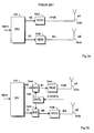
- Figure 7A shows a prior art transmitter and Figure 7B shows a transmitter according to a preferred embodiment of the invention.
- the transmitters comprise a block DIV 700, which receives a bit stream and divides it between the antennas.
- the bits received in Figure 7A are modulated in blocks 702A and 702B and transmitted to the radio path via antennas 500A and 500B, respectively.
- the transmission channels to be transmitted via the transmitting antennas 500A, 500B have particular time-dependent channel coefficients c1 and c2, respectively, that describe the fading and delay caused by the channel in the signal.
- Figure 7B shows a transmitter according to a preferred embodiment of the invention, which comprises means 704A and 704B for providing bit-to-symbol mapping.
- block 704A converts received bits 10 to bits 01
- block 704B carries out bit conversion 11 ⁇ 00.
- the bits obtained from the outputs of means 704A and 704B are further guided to modulation blocks 702A and 702B for transmission via transmitting antennas 500A and 500B.
- the means for providing bit-to-symbol mapping are guided by bit-to-symbol mapping control means 706, which receive, as input, for example channel information or information about the status of the constellation point system used.
- the aforementioned means and the other means implementing the method according to the invention are realized in the receiver e.g. by means of software, separate logical components or ASICs.
Landscapes
- Engineering & Computer Science (AREA)
- Computer Networks & Wireless Communication (AREA)
- Signal Processing (AREA)
- Quality & Reliability (AREA)
- Mobile Radio Communication Systems (AREA)
- Radio Transmission System (AREA)
- Fittings On The Vehicle Exterior For Carrying Loads, And Devices For Holding Or Mounting Articles (AREA)
- Closed-Circuit Television Systems (AREA)
- Stereoscopic And Panoramic Photography (AREA)
Abstract
Description
- The invention is applied in mobile systems, particularly systems where information is transmitted between a transmitter and a receiver via at least two transmitting antennas.
- In a mobile system, several transmitting antennas are employed to transmit user information in the downlink direction. In the uplink direction the use of several antennas will probably become relevant with the new media terminals. Use of a plurality of transmit antenna branches e.g. in a mobile system base station provides diversity gains over the radio connection. Diversity gains are obtained e.g. by means of coherent signal combination and more effective prevention of fading.
- The values a signal obtains over the radio connection are modelled by means of complex numbers, where the absolute value or module of the complex number represents signal amplitude and the polar angle or argument of the complex number represents signal phase. The signals transmitted via different antennas are summed in the combined signal propagating over the radio path, the complex values of the signal thus corresponding to the sums of the values obtained by the signals transmitted via different antennas. The set of values the combined signal has obtained in the complex plane is referred to as a combined constellation. A combined constellation is utilized in the receiver for deducing, from the complex value of the combined signal, the signals transmitted from different antenna branches of the transmitter and combined over the radio path to provide the received complex value. In several cases the received complex value does not fully correspond to any constellation point, and the receiver must therefore make a decision for example on the basis of the constellation point that is closest to the received complex value. As the receiver moves in the radio system, the combined constellation is also continuously altered since the transmission channels change e.g. due to different propagation paths of the signals.
- Article of da Silva and de Assis, "Transmission scheme using fading-resistant constellations" discloses a scheme combining space diversity and multidimensional constellations, in order to achieve efficient transmission over slow fading channels. The idea is to map information bits to points of a N-dimensional signal constellation and project these points on certain sub-spaces.
-
EP 0998 045 discloses a tranmission method for transmission of a multilevel modulated signal. The soft output information of a channel decoder is fed back and utilised by a soft demapping device in order to improve the decoding result by further iterative decoding steps. - The prior art arrangements are able to react to the changing values or locations of the constellation points in the complex plane. However, in these arrangements the bit-to-symbol mapping remains constant during the connection, i.e. mapping of bits to symbols is independent of the channel status. Since the bit-to-symbol mapping is fixed and radio channel statuses keep changing, the likelihood of erroneous bit decisions made by the receiver increases, thus reducing the accuracy of identification of the transmitted information in the receiver.
- An objective of the invention is to provide an improved method and equipment implementing the method for making correct bit decisions in the receiver. This is achieved by a method according to
claim 1 and by apparatus according to claims 12 and 21. - The preferred embodiments of the invention are disclosed in the dependent claims.
- The invention can be applied in digital radio systems, such as mobile systems. The arrangement according to the invention, which relates to transmission of information between the transmitter and the receiver, is not restricted to the data transmission direction used, but it can be applied to both uplink and downlink transmission. This means that a radio system base station and a terminal equipment operating in the network area can both operate as a transmitter and a receiver. The only restriction is that the transmitter must transmit via at least two transmitting antennas.
- In the method, information bits to be transmitted by the transmitter are mapped by means of adaptive bit-to-symbol mapping to channel symbols to be transmitted on a transmission channel. Adaptivity means herein that the bit-to-symbol mapping and the combined constellation related thereto are altered with the changing radio channel status. A change in the radio channel status is detected by means of measurements performed on the channel.
- In the receiver bit decisions are carried out on the basis of the values of the received combined signal and the combined constellation used. Whenever the radio channel changes, i.e. the transmission channel transmitted via an antenna changes, the values of the combined constellation must be updated. In a preferred embodiment of the invention, a combined constellation is formed by summing up all the possible combinations of the channel symbols to be transmitted via different transmitting antennas, the symbols being multiplied by channel coefficients corresponding to the transmission channels. The mapping of bits to channel symbols utilizes channel-dependent bit-to-symbol mapping. In another preferred embodiment, the mapping and the resulting combined constellation are selected from a predetermined set of constellations known to the transmitter and the receiver.
- Radio channel status can be determined by several methods. The status is preferably determined by means of channel coefficients, each of which corresponds to a particular transmission channel or antenna. A channel coefficient represents the amplitude and phase of the signal transmitted on the transmission channel at one or more instants. Therefore the invention is not restricted to the channel model used, but it can be applied in connection with channel models of one or more taps. The radio channel status or channel parameter can also be given in the form of a phase difference or amplitude difference between antennas.
- In a preferred embodiment, the radio channel status is determined in the receiver, which forms an estimate of the channel status by means of the received signal, and signals the estimate to the transmitter. In another preferred embodiment, both the transmitter and the receiver form an estimate of the transmission channel. This embodiment is applicable for example in radio systems based on time division duplex (TDD). In an embodiment, only the transmitter measures the channel, and if needed, it signals channel-related information to the receiver.
- Channel-related information is only signalled if necessary, i.e. for example when only the receiver measures the channel and the channel status has changed to such an extent that the bit-to-symbol mapping scheme has to be updated to correspond to the channel status. For example in connection with a channel coefficient, a change in the channel status can be estimated by setting a threshold value for a change of the coefficient, exceeding of the threshold value resulting in a changing bit-to-symbol mapping scheme. The bit-to-symbol mapping scheme and the related combined constellation can also be updated for example periodically.
- The bit-to-symbol mapping and the related mapping of information bits to binary indices preferably employ such a mapping scheme that results in the combined constellation in a minimum Hamming distance between adjacent constellation points.
- The invention will be described below in more detail in connection with the preferred embodiments and with reference to the accompanying drawings, in which
-
Figure 1 shows a preferred embodiment of a method according to the invention, -
Figure 2A shows an arrangement based on a fixed mapping scheme, -
Figure 2B shows, at a first instant, a bit-to-symbol mapping scheme changing according to channel status, -
Figure 2C shows, at a second instant, a bit-to-symbol mapping scheme changing according to the channel status, -
Figure 3A shows a constellation provided by fixed modulation mapping in the case of first channel coefficients, -
Figure 3B shows a combined constellation provided by fixed mapping in the case of second channel coefficients, -
Figure 3C shows a constellation changing according to the channel status in the case of the first channel coefficients, -
Figure 3D shows the constellation changing according to the channel status in the case of the second channel coefficients, -
Figure 4 shows a structural diagram of the structure of UMTS, -
Figure 5 shows an embodiment of an arrangement according to the invention, -
Figure 6 shows a preferred structure of a transmitter and a receiver according to the invention, -
Figure 7A shows a prior art transmitter, and -
Figure 7B shows a transmitter according to a preferred embodiment of the invention. - The invention will be described below by means of preferred embodiments and with reference to the accompanying drawings.
Figure 1 shows a preferred embodiment of the method according to the invention. The figure shows signalling between a base station BTS and a mobile station MS and the operations carried out in these network parts. The first step 1-2 of the method comprises downlink transmission of information, such as user or control information. Information bits are converted into channel symbols according to the current bit-to-symbol mapping scheme for transmission via two or more transmitting antennas. The information to be transmitted can be divided in several manners to the antennas. For example in the case of two antennas, the information can be split in two such that two bits are transmitted via the first antenna, two bits via the second antenna, two bits again via the first antenna and so forth. It is also possible to transmit all the information via both antennas, in which case the information is transmitted via the second antenna in an interleaved, delayed or coded form. - Method step 1-4 of
Figure 1 comprises transmitting information from the transmitter BTS via at least two antennas. The pieces of information transmitted via different antennas are summed up over the radio path into a combined signal received in the receiver MS. In method step 1-6, the receiver MS forms channel parameters from the radio channel, i.e. estimates of the channels that were used to transmit the information. The transmissions sent via the antennas are separated and channel coefficients based on e.g. a one-tap channel model are formed from the channels. It is simultaneously estimated whether the channel parameters have changed to such an extent that the constellation point system in use should be updated. In method step 1-8, the receiver MS decomposes the received information by forming estimates of the transmitted symbols. The estimates are formed based on the constellation point system, which includes possible values of the combined signal that are used in an optimum receiver for selecting the constellation point closest to the value of the received signal. - Method step 1-10 describes transmission of a channel parameter from the receiver to the transmitter. A channel parameter can be transmitted e.g. on a control channel in a particular field once during a transmission frame, for instance. The channel parameter value can comprise channel information in various forms, such as the value of the channel coefficient, exceeding of the threshold value for the channel coefficient, or a number representing the antenna-specific bit-to-symbol mapping scheme to be used next. In method step 1-12, the transmitter utilizes the information received in step 1-10 to estimate whether the constellation point system should be updated. As an example, it is shown in method step 1-12 that the combined constellation is recalculated and the bit-to-symbol mapping scheme to be used is also reformed. It is assumed in
Figure 1 that the updating of the constellation point system is controlled by the transmitter BTS, which then informs the receiver in step 1-14 about the changing mapping scheme so that the receiver can reform the combined constellation to be used. The receiver calculates or starts using another constellation in step 1-16. When both the transmitter and the receiver know the new point system and the corresponding bit-to-symbol mapping scheme, the next frame can be transmitted in the recurring step 1-4 by means of the updated point system. - The method according to the invention will be illustrated below with reference to
Figures 2A to 3D .Figures 2A ,3A and 3B refer to a prior art arrangement andFigures 2B, 2C ,3C and 3D to an arrangement according to the invention. It is assumed in both examples that the binary word to be transmitted is [0111] and it is divided between the transmitting antennas such that the first antenna transmits binary word [01] and the second antenna transmits binary word [11]. The transmission of the aforementioned binary word is described by way of an example at two instants with different channel coefficients of the transmission channels. It is further assumed that the prior art arrangement utilizes a fixed modulation mapping scheme according to the QPSK modulation method as shown inFigure 2A in both transmitting antennas at each instant.Bit combination 00 thus corresponds to complex channel symbol (1+0i),bit combination 01 corresponds to symbol (0+1i),combination 10 corresponds to symbol (-1+0i) andcombination 11 corresponds to symbol (0-1i). The arrangement according to the invention in turn utilizes, at the first instant, the mapping scheme shown inFigure 2B . The constellation used by the first transmitting antenna is shown on the left inFigure 2B and the modulation constellation used by the second transmitting antenna is shown on the right.Figure 2C in turn shows the modulation constellations used at the second instant in the bit-to-symbol mapping scheme of the arrangement according to the invention, the constellation of the first antenna being shown on the left and the constellation of the second antenna on the right. - The prior art arrangement is compared to the arrangement according to the invention by assuming that the signals to be transmitted via the transmitting antennas are mapped by means of a one-tap channel model, the channel coefficient of the first channel at the first instant being c1=1.4+1.1i and the channel coefficient of the second channel being c2=-2.0-0.9i. The combined constellation used by the receiver for bit decisions can be formed by summing up the product of c1 and the QPSK modulation points and the product of c2 and the QPSK modulation points. Examine first
Figure 3A , which shows the constellation point system formed with the aforementioned channel coefficients. The values of the constellation points are shown in Table 1 in a situation where the first two bits of a 4-bit information section are transmitted via the first antenna and the last two bits via the second antenna.Table 1. Calculation of constellation points Binary index Calculation of signal value Signal value 0 (0000) (1.4+1.1i)(1+0i)+(-2.0-0.9i)(1+0i) -0.6+0.2i 1 (0001) c1(1+0i)+c2(0+1i) -2.3-0.9i 2 (0010) c1(1+0i)+c2(-1+0i) 3.4+2i ... ... ... 7 (0111) c1(0+1i)+c2(1+0i) -2.0+3.4i ... ... ... - With reference to Table 1,
Figure 2A shows two different bit values in the complex plane. Binary word [0111] examined in this example thus corresponds to value (-2.0+3.4i) in the complex plane, which is a signal received by the receiver. Thus, the receiver makes decisions about the value of the received signal on the basis of the combined constellation shown inFigure 2A .Figure 3A clearly shows that there is a great likelihood of bit error decisions in the receiver. For example the points corresponding to binary words [0100] and [1011] are situated adjacent to one another in the complex plane. An erroneous decision with respect to these binary words would result in a maximum error of four bits. - Assume that the transmission channel changes and the new channel coefficients are c1=0.1-1.5i and c2=0.5+0.3i. Therefore with the binary word [0111] used in the example, the prior art arrangement would provide the received signal with the value (0+1i)(0.1-1.5i)+(0-i)(0.5+0.3i)=1.8-0.4i. It is evident that the signal value the receiver has received differs significantly from the first instant, i.e. the signal value has changed from (-2.0+3.4i) to (1.8-0.4i). Due to the new channel coefficients, the locations of the binary words in the complex plane have also changed considerably. Furthermore, the binary words are not at all optimally located in view of signal decisions carried out by the receiver.
- Examine below the arrangement according to the invention with reference to
Figures 3C and 3D. Figure 3C shows the constellation of a combined signal transmitted by the antennas in the case of the channel coefficients of the first instant, i.e. c1=1.4+1.1i and c2=-2.0-0.9i. InFigure 3D , the channel coefficients are the coefficients of the second instant, i.e. c1=0.1-1.5i and c2=0.5+0.3i. At the first instant, the transmitter utilizes the antenna-specific mapping schemes shown inFigure 2B and at the second instant the mapping schemes shown inFigure 2C . Comparison of the combined signal constellations shown inFigures 3C and 3D shows that the order of points in the constellation remains constant and only the distances between the points have changed along with the altered channel coefficients. Since the order of the constellation is the same inFigures 3C and 3D , the receiver can select for use the combined constellation with optimum protection against error decisions by the receiver. The constellation shows that the constellation points are arranged with a minimum Hamming distance of 1 between adjacent points. Therefore possible erroneous bit decisions will be mostly likely restricted to 1-bit errors. In a situation according to a preferred embodiment of the invention shown inFigures 3C and 3D , the binary words to be transmitted are subjected to bit-to-symbol mapping by means of different modulation constellations for different values of channel coefficients. Suitable rotation of the modulation constellation thus provides a bit conversion resulting in the optimum reception constellation for the channel symbols shown inFigures 3C and 3D . In this arrangement, the transmitter and the receiver must be aware of the measured channel parameters and the mapping scheme to be used, and the coordination of these matters will be described below in connection with an arrangement illustrating the invention. With further reference to the method described above, it is evident that the order of the combined constellation shown inFigures 3C and 3D is only illustrated by way of an example, and the arrangement according to the invention is not restricted to the above description, nor is it naturally restricted to the modulation method used or the manner of dividing the information to be transmitted to the transmitting antennas. The invention will be described below with respect to the aforementioned arrangement and with reference toFigures 4 to 7 . The equipment alternatives shown herein are not exhaustive, but it is evident to a person skilled in the art that the figures do not need to be described in more detail in order to illustrate the arrangement according to the invention. The description of the equipment contains references to a universal mobile telephony system (UMTS) without restricting the invention thereto, however.Figure 4 shows generally the structure of the UMTS. The main elements of the system are a core network CN, a UMTS terrestrial radio access network UTRAN and a user equipment UE, which has been referred to as a mobile station MS inFigure 1 . The interface between the CN and the UTRAN is referred to as an lu interface, and the air interface between the UTRAN and the UE is referred to as a Uu interface. The functionality related to a radio connection to the UE is carried out in the UTRAN. The CN in turn manages routing and connections to systems outside the UMTS, such as a public switched telephone network PSTN and the Internet. The user equipment consists of two parts: a mobile equipment ME used as a radio terminal responsible for communication over the Uu interface, and a UMTS subscriber identity module USIM that is a smart card containing data required for user identification and authentication. The UTRAN comprises one or more radio network subsystems RNS, each of which in turn consists of at least one radio network controller RNC and nodes B or base stations denoted by BTS inFigure 1 . The primary function of node B is to manage the air interface to the UE and the related processing, such as channel coding, interleaving, power control and spreading of user signals. The RNC that controls node B in turn manages the UTRAN radio resources, the loading of the cells C of the RNC and the functionality related to allocation of new spreading codes in the cells. The core network comprises a gateway MSC GMSC providing access to external networks, a home location register HLR, a mobile services switching centre MSC, a visitor location register VLR, and a serving GPRS (General Packet Radio Service) support node SGSN providing packet switched connections with routing services. The Uu radio interface is a three-layer protocol stack comprising a physical layer L1, a data link layer L2 and a network layer L3. The data link layer L2 is further divided into two sublayers, i.e. radio link control RLC and medium access control MAC. The L3 and the LAC are further divided into control C and user U planes. The L1 provides the transmission channels with information transfer services to the MAC and the higher layers. The L2/MAC in turn transmits the information between the physical transmission channels and the logical channels that are higher on the protocol stack. Logical channels can be divided into control channels and traffic channels according to their functionality. UTRAN control channels include a broadcast control channel (BCCH) used for downlink transmission of system control information to the terminal equipments, a paging control channel (PCCH) for transmitting paging information for locating a terminal equipment in a cell, a dedicated control channel (DCCH) that is a bidirectional channel for transmitting control information between a terminal equipment and the network, and a common control channel (CCCH) that is a bidirectional channel for transmitting control information between a terminal equipment and the network and that is always linked to transmission channels related to call set-up, i.e. a random access channel (RACH) and a forward access channel (FACH). Traffic channels include a dedicated traffic channel (DTCH) that is a bidirectional traffic channel dedicated to one terminal equipment for transmitting user information, and a common traffic channel (CTCH) that is a point-to-multipoint channel for transmitting traffic information simultaneously to one or more terminals. With respect to transmission channels it can be stated by way of an example that e.g. logical channel BCCH is implemented on transmission channel BCH, logical channel DTCH is implemented on transmission channel DCH and logical channel PCCH on transmission channel PCH. The transmission channels are implemented in the physical protocol layer L1 by means of physical channels. For example DTCH is implemented in the physical layer in a downlink dedicated physical channel (Downlink DPCH). In the uplink transmission direction, the modulation method is BPSK and in the downlink direction it is QPSK. The frame and burst structures used in the physical channels differ from one another depending on the physical channel used for transmission. For example in Downlink DPCH, a transmission frame of 10 ms includes 15 time slots, each of which has a duration of 0.667 ms. A data packet to be transmitted in a time slot is referred to as a burst, each burst consisting of 2560 chips. In one burst,chips 0 to 1103 typically contain data, chips 1104 to 1359 contain a training sequence, chips 1360 to 2463 contain again data, and the end of the burst comprises a 96-chip guard period. The training sequence consists of a number of symbols that are known both to the transmitter and the receiver and are used by the receiver to conclude the distortion produced in the information over the transmission path, this data on the distortion enabling the receiver to correct the information, if required. A training sequence to be used on an uplink channel is usually longer in order to facilitate the separation of bursts received by the base station from different users. The above description illustrates the UMTS very generally. With reference to the channels used in the UMTS, the bit-to-symbol mapping according to the invention can be performed on information transmitted both on channels dedicated to a user and on the common control channels. The direction of transmission can be either downlink or uplink, the only restriction resulting from the physical properties of the equipment, such as whether the terminal equipment is suitable for implementing a system with two transmitting antennas.Figure 5 shows a base station BTS and a mobile station MS located in the coverage area of the base station and communicating with the base station over a bidirectional radio connection. Instead of the communication shown in the figure between the base station BTS and the mobile station MS, the arrangement according to the invention also enables transmission of information between base stations over the radio path, if required. InFigure 5 , downlink transmission from the base station BTS takes place via two transmittingantennas transmission channels transmission channels antenna 504 and they can be combined coherently in the receiver. The figure also shows anuplink control channel 506 for transmitting control information from the mobile station MS to the base station BTS. Instead of or in addition to the control channel, the control information can also be transmitted by means of the data transmission capacity provided by user information, i.e. the control information can be adapted to the user information in a known manner. The need to transmit control information is the greatest particularly in cellular radio systems based on frequency division duplex (FDD), where the uplink and downlink directions are implemented at different frequency ranges. In systems based on TDD, both the transmitter and the receiver can independently carry out measurements on the communication channels used, and if the constellation point system is updated periodically or in some other manner according to common operating principles, there may be no need to transmit control information between the transmitter and the receiver. - The steps related to transmission of information to the physical channels of the radio path by the transmitter-receiver technique will be described below with reference to
Figure 6 . In the situation according to the invention, a radio transmitter is located for example in a base station B/BTS and a radio receiver is situated e.g. in a subscriber terminal UE/MS. The upper half ofFigure 6 shows the essential functions of the radio transmitter, such that the upper row illustrates the steps of processing the control channel, and the lower row illustrates the steps of processing the traffic channel before the channels are combined and transmitted to the physical channel of the radio connection. Theinformation 600B to be placed on the traffic channel includes speech, data and moving or still video image. The control channel is provided withcontrol information 600A, such as system information, which in the case of a pilot channel consists of the pilot bits forming the training sequence and used by the receiver for channel estimation. The channels are subjected to channel coding inblocks interleaver blocks indices - The chips obtained from the spreading are scrambled by a base-station-specific scrambling code and modulated in
block 606, which also comprises the other measures required by the method according to the invention. Thus, block 606 comprises e.g. means for mapping the bits to channel symbols and means for forming a new bit-to-symbol mapping scheme or means for selecting a new mapping scheme based on the control information. If required, block 606 also comprises means for forming control information with which the transmitter and the receiver are able to use the same combined constellation. Block 606 also comprises means according to certain embodiments for setting a threshold value for the channel parameter and means for comparing the channel parameter to the set threshold value. The aforementioned means according of the preferred embodiments of the method according to the invention and the means according to the other preferred embodiments are implemented in the transmitter e.g. by means of software, separate logical components or ASICs (Application Specific Integrated Circuit). Furthermore, the signals obtained from different channels are combined inblock 606 for transmission via the same transmitter. The combined signal is finally supplied to radio-frequency parts 608, which can comprise various power amplifiers and filters restricting the bandwidth. An analog radio signal is transmitted via at least two transmittingantennas
The lower half ofFigure 6 shows the essential functions of the radio receiver, which is typically a rake receiver. The analog radio-frequency signal is received from the radio path Uu by a receivingantenna 504. The signal is supplied to radio-frequency parts 620 and converted into an intermediate frequency or directly into a baseband, and the analog signal is sampled and quantized. Since the signal has propagated via several paths, the different multipath-propagated signal components are to be combined inblock 622 comprising the actual rake fingers of the receiver. The information is composed from the combined signal by multiplying the signal with the user's spreading code. Block 622 also comprises carrying out the functions that are in accordance with the method according to the invention and required by the receiver of the invention. Therefore block 622 preferably comprises e.g. means for measuring the status of the radio channel for transmitting information, means for mapping channel symbols to bits, means for forming a new combined constellation and means for selecting a new constellation point system based on the control information. If required, block 622 also comprises means for forming control information with which the transmitter and the receiver can use the same constellation point system. In order to form a new combined constellation, the receiver only has to have information on the channel, e.g. channel coefficients. When the receiver knows the locations of the general points of the combined constellation with respect to one another, it can use the channel coefficients to independently form a new combined constellation. The only matter to be co-ordinated by the receiver and the transmitter is the instant of introducing the new constellation. Block 622 also comprises means according to certain embodiments for setting a threshold value for the channel parameter and means for comparing the channel parameter to the set threshold value. The means according to the preferred embodiments of the method of the invention and the means according to the other preferred embodiments are implemented in the receiver e.g. by means of software, separate logical components or ASICs (Application Specific Integrated Circuit).
The obtained physical channel is deinterleaved in deinterleaving means 624, and the deinterleaved physical channel is divided in ademultiplexer 626 into data streams for different channels. Each channel is guided into a separatechannel decoding block control information 630A and theuser data 630B transmitted from the transmitter. - Even though the above description relates to the operations according to the invention carried out in
blocks example block 606 is preferably provided with feedback to block 600A, which actually forms the control information for providing a new constellation point system. -
Figure 7A shows a prior art transmitter andFigure 7B shows a transmitter according to a preferred embodiment of the invention. The transmitters comprise ablock DIV 700, which receives a bit stream and divides it between the antennas. The bits received inFigure 7A are modulated inblocks antennas antennas Figure 7B shows a transmitter according to a preferred embodiment of the invention, which comprises means 704A and 704B for providing bit-to-symbol mapping. Forexample block 704A converts receivedbits 10 tobits 01, and block 704B carries outbit conversion 11→00. The bits obtained from the outputs ofmeans modulation blocks antennas - Even though the invention is described above with respect to the example according to the accompanying drawings, it is clear that the invention is not restricted thereto but it can be modified in various manners within the scope of the inventive idea disclosed in the appended claims.
Claims (24)
- A method for transmitting information between a transmitter and a receiver in a mobile system, comprising:mapping bits contained in the information to be transmitted with antenna-specific bit-to-symbol mappings in the transmitter to channel symbols (1-2);transmitting (1-4) the channel symbols to a radio channel via at least two transmitting antennas;receiving (1-10) a measurement report of the status of the radio channel used for transmitting information (1-6), characterized by:forming a combined constellation of the antenna-specific mappings and the status of the radio channel;changing (1-12) a binary representation of a channel symbol in at least one of the antenna-specific bit-to-symbol mapping schemes on the basis of the measured radio channel status such that the relative order of the constellation points in the combined constellation remains constant.
- A method according to claim 1, characterized by changing (1-12) the channel symbols to be transmitted via different antennas in the bit-to-symbol mapping such that the value of the signal to be transmitted to the receiver corresponds to the radio channel status in the combined constellation.
- A method according to claim 1, characterized in that when the bit-to-symbol mapping scheme is to be changed (1-12),
all the possible combinations of symbols multiplied with channel parameters and to be transmitted via the different antennas are summed up to form a combined constellation. - A method according to claim 1, characterized in that when the bit-to-symbol mapping scheme is to be changed (1-12),
the transmitter utilizes a mapping group containing at least two predetermined mapping schemes and selects the mapping scheme to be used from the mapping group on the basis of the measured status of the radio channel. - A method according to claim 1, characterized in that during measurement of the radio channel status, a channel parameter is formed (1-6) to represent one or more of the following: channel coefficients of transmission channels formed by transmitting antennas, a phase difference or an amplitude difference between two antennas, an identifier of the mapping scheme to be used.
- A method according to claim 1, characterized by changing (1-12) the bit-to-symbol mapping scheme periodically to correspond to the status of the transmission channel.
- A method according to claim 1, characterized by setting (1-6) a threshold value for a channel coefficient describing the phase and amplitude of the signal to be transmitted at one or several instants, exceeding of the threshold value resulting in reformation of the bit-to-symbol mapping scheme.
- A method according to claim 1, characterized in that during the measurement of the radio channel status, a channel parameter representing the radio channel status is formed (1-8) in one or more of the following manners: measuring the channel status in the receiver, measuring the channel status in the transmitter, measuring the channel status in both the transmitter and the receiver.
- A method according to claim 8, characterized by transmitting (1-10) the channel parameter representing the channel status from the transmitter to the receiver or vice versa.
- A method according to claim 1, characterized in that the method comprises transmitting (1-4) at least some of the information bits via a first transmitting antenna of the transmitter transmitting to the first transmission channel, and at least some of the information bits via at least one other transmitting antenna of the transmitter transmitting to the other transmission channels, the information transmitted to the first channel and to the other transmission channels forming a combined signal on the radio path, the values obtained by the signal being represented in the system by a combined constellation and the combined signal being received in the receiver, which carries out symbol and bit decisions on the information in the received combined signal on the basis of the combined constellation.
- A method according to claim 10, characterized by arranging (1-12) binary indices in the combined constellation of the bit-to-symbol mapping scheme such that the Hamming distance between adjacent constellation points is at a minimum.
- A transmitter for use in a mobile system, comprising:mapping means (704A-704B) for mapping bits of the information to be transmitted to channel symbols antenna-specifically;at least two transmitting antennas (500A-500B) for transmitting the channel symbols to a radio channel of the mobile system;means for processing (706) measurement information on the status of the mobile system radio channel, characterized in that the transmitter comprises:means for forming a combined constellation of the antenna-specific bit-to-symbol mappings and the status of the radio channel, the mapping means (704A-704B) are arranged to change a binary representation of a channel symbol in at least one of the antenna-specific bit-to-symbol mappings on the basis of the measured radio channel status such that the relative order of the constellation points in the combined constellation remains constant.
- A transmitter according to claim 12, characterized in that information to be transmitted on the mobile system radio channel is described by means of a combined constellation, and that the mobile system is arranged to use a bit-to-symbol mapping scheme resulting in a combined constellation where the Hamming distance between adjacent constellation points is at a minimum.
- A transmitter according to claim 12, characterized in that the mapping means (704) are arranged to utilize, in the transmitter, a mapping group containing at least two predetermined bit-to-symbol mapping schemes and to select an antenna-specific bit-to-symbol mapping scheme from the mapping group on the basis of the measured radio channel status.
- A transmitter according to claim 12, characterized in that the processing means are arranged to form information representing the channel status and describing one or more of the following: channel coefficients of transmission channels formed by transmitting antennas, a phase difference or an amplitude difference between two antennas, an identifier of the mapping scheme to be used.
- A transmitter according to claim 12, characterized in that when the bit-to-symbol mapping scheme is being formed, the mapping means (704) are arranged to
sum up all the possible combinations of symbols multiplied with channel parameters and to be transmitted via different antennas to form a combined constellation. - A transmitter according to claim 12, characterized in that the mapping means (704) are arranged to utilize, in the transmitter, a mapping group containing at least two predetermined bit-to-symbol mapping schemes and to select the bit-to-symbol mapping scheme to be used from the mapping group on the basis of the measured radio channel status.
- A transmitter according to claim 12, characterized in that the transmitter is arranged to use a bit-to-symbol mapping scheme that changes periodically according to the status of the transmission channel.
- A transmitter according to claim 12, characterized in that the mobile system is arranged to set a threshold value for the channel coefficient representing the phase and amplitude of the signal to be transmitted at one or several instants, exceeding of the threshold value resulting in reformation of the bit-to-symbol mapping scheme by the transmitter.
- A transmitter according to claim 12, characterized in that the measuring means are arranged to form the channel parameter representing the radio channel status in one of the following manners: measuring the channel status in the receiver, measuring the channel status in the transmitter, measuring the channel status both in the transmitter and receiver.
- A receiver for use in a mobile system, comprising means for receiving (504) a combined signal consisting of signals transmitted via at least two transmitting antennas (500A-500B) and mapped with antenna-specific bit-to-symbol mappings, and means for carrying out bit decisions (622) on the combined signal by means of a combined constellation that represents the values the received signal obtains in the complex plane, and means for processing (622) measurement information on the radio channel used in the transmission of the received signal,
characterized in that the receiver comprises means for reforming the combined constellation used for bit decisions by changing a binary representation of the channel symbols for at least one of the antenna-specific bit to symbol mappings on the basis of the measurement information of the radio channel such that the relative order of the constellation points in the combined constellation remains constant. - A receiver according to claim 21, characterized in that the radio channel status is described by means of a channel parameter, such as channel coefficients of the transmission channels transmitted via the transmitting antennas, or a phase or amplitude difference between the antennas.
- A receiver according to claim 21, characterized in that the receiver comprises means for receiving (620) the control information from the transmitter in order to reform the combined constellation.
- A receiver according to claim 21, characterized in that the receiver is arranged to utilize a combined constellation where the Hamming distance between adjacent constellation points is at a minimum for carrying out bit decisions.
Applications Claiming Priority (3)
| Application Number | Priority Date | Filing Date | Title |
|---|---|---|---|
| FI20010963 | 2001-05-08 | ||
| FI20010963A FI20010963A0 (en) | 2001-05-08 | 2001-05-08 | Adaptive Symbol Description in a Mobile System |
| PCT/FI2002/000388 WO2002091695A1 (en) | 2001-05-08 | 2002-05-07 | Adaptive symbol mapping in mobile system |
Publications (2)
| Publication Number | Publication Date |
|---|---|
| EP1396128A1 EP1396128A1 (en) | 2004-03-10 |
| EP1396128B1 true EP1396128B1 (en) | 2010-07-07 |
Family
ID=8561151
Family Applications (1)
| Application Number | Title | Priority Date | Filing Date |
|---|---|---|---|
| EP02722315A Expired - Lifetime EP1396128B1 (en) | 2001-05-08 | 2002-05-07 | Adaptive symbol mapping in mobile system |
Country Status (7)
| Country | Link |
|---|---|
| US (1) | US7308036B2 (en) |
| EP (1) | EP1396128B1 (en) |
| CN (1) | CN1520668A (en) |
| AT (1) | ATE473576T1 (en) |
| DE (1) | DE60236932D1 (en) |
| FI (1) | FI20010963A0 (en) |
| WO (1) | WO2002091695A1 (en) |
Families Citing this family (7)
| Publication number | Priority date | Publication date | Assignee | Title |
|---|---|---|---|---|
| KR100976475B1 (en) * | 2003-08-19 | 2010-08-18 | 엘지전자 주식회사 | Method of securing quality of communication service |
| JP4269858B2 (en) * | 2003-09-10 | 2009-05-27 | 株式会社日立製作所 | Adaptive modulation / demodulation method and wireless communication system |
| KR100744336B1 (en) * | 2004-06-18 | 2007-07-30 | 삼성전자주식회사 | Handover method for ofdm-based wireless communication system |
| GB2415860B (en) * | 2004-06-30 | 2007-04-18 | Nokia Corp | A method of providing a radio service at a remote terminal |
| EP1764934B1 (en) * | 2005-09-15 | 2022-03-30 | Huawei Technologies Co., Ltd. | Method for generating a frame in an orthogonal frequency division multiple access communication system |
| KR100809604B1 (en) * | 2006-12-06 | 2008-03-04 | 한국전자통신연구원 | Apparatus and method for transmitting/receiving signals using the signaling point rotation at the mutual cooperation transmission |
| US8498243B2 (en) * | 2008-06-11 | 2013-07-30 | Qualcomm Incorporated | Apparatus and method for channel error control of non-exclusive multiplexing for control channels |
Family Cites Families (9)
| Publication number | Priority date | Publication date | Assignee | Title |
|---|---|---|---|---|
| US5289501A (en) * | 1991-11-26 | 1994-02-22 | At&T Bell Laboratories | Coded modulation with unequal error protection for fading channels |
| US5479448A (en) * | 1992-03-31 | 1995-12-26 | At&T Corp. | Method and apparatus for providing antenna diversity |
| US5696794A (en) | 1996-04-04 | 1997-12-09 | Motorola, Inc. | Method and apparatus for conditioning digitally modulated signals using channel symbol adjustment |
| EP0998045A1 (en) * | 1998-10-30 | 2000-05-03 | Lucent Technologies Inc. | Digital transmission system and method |
| US6594473B1 (en) * | 1999-05-28 | 2003-07-15 | Texas Instruments Incorporated | Wireless system with transmitter having multiple transmit antennas and combining open loop and closed loop transmit diversities |
| US6490270B1 (en) * | 1999-07-27 | 2002-12-03 | Lucent Technologies Inc. | Modulation method for transmitter |
| US6782037B1 (en) | 1999-07-27 | 2004-08-24 | Lucent Technologies Inc. | Demodulation method for receiver |
| US6771706B2 (en) * | 2001-03-23 | 2004-08-03 | Qualcomm Incorporated | Method and apparatus for utilizing channel state information in a wireless communication system |
| US8290098B2 (en) * | 2001-03-30 | 2012-10-16 | Texas Instruments Incorporated | Closed loop multiple transmit, multiple receive antenna wireless communication system |
-
2001
- 2001-05-08 FI FI20010963A patent/FI20010963A0/en unknown
-
2002
- 2002-05-07 EP EP02722315A patent/EP1396128B1/en not_active Expired - Lifetime
- 2002-05-07 CN CNA028095049A patent/CN1520668A/en active Pending
- 2002-05-07 WO PCT/FI2002/000388 patent/WO2002091695A1/en not_active Application Discontinuation
- 2002-05-07 AT AT02722315T patent/ATE473576T1/en not_active IP Right Cessation
- 2002-05-07 DE DE60236932T patent/DE60236932D1/en not_active Expired - Lifetime
-
2003
- 2003-11-06 US US10/701,602 patent/US7308036B2/en not_active Expired - Fee Related
Also Published As
| Publication number | Publication date |
|---|---|
| EP1396128A1 (en) | 2004-03-10 |
| US20040101063A1 (en) | 2004-05-27 |
| WO2002091695A1 (en) | 2002-11-14 |
| CN1520668A (en) | 2004-08-11 |
| DE60236932D1 (en) | 2010-08-19 |
| US7308036B2 (en) | 2007-12-11 |
| ATE473576T1 (en) | 2010-07-15 |
| FI20010963A0 (en) | 2001-05-08 |
Similar Documents
| Publication | Publication Date | Title |
|---|---|---|
| EP1114526B2 (en) | Method of identifying information addressed to a user in a communication system, and a communication system | |
| EP1075736B1 (en) | Transmit diversity methods, systems, and terminals using scramble coding | |
| EP1157483B1 (en) | Method and system using transmit diversity techniques | |
| US7949066B2 (en) | Method and apparatus for providing high speed data communications in a cellular environment | |
| EP1772969B1 (en) | Subscriber unit for CDMA wireless communication system | |
| FI105961B (en) | Reception procedure and recipients | |
| US6442146B1 (en) | Time-division multiple-access communication system | |
| US6646993B1 (en) | Communication apparatus and method of format adaptation therefor | |
| US5574989A (en) | Time division multiple access cellular communication system and method employing base station diversity transmission | |
| FI106663B (en) | Communication method and radio system | |
| EP1396128B1 (en) | Adaptive symbol mapping in mobile system | |
| EP1145573A3 (en) | Communication system with reduced power variation and method therefor | |
| US7440740B2 (en) | Method of transmitting data where in a first mode, the power level is not indicated in a message and an NPSK modulation scheme is used, and in a second mode, the power level is indicated in a message in an NQAM modulation scheme is used | |
| US20140362760A1 (en) | Method and apparatus for providing multi-rate broadcast services | |
| WO2001050670A1 (en) | Method of coding a signal, transmitter and receiver | |
| Sousa | CELLULAR RADIO | |
| WO2000008771A1 (en) | Method and apparatus for rotating modulation symbol indices |
Legal Events
| Date | Code | Title | Description |
|---|---|---|---|
| PUAI | Public reference made under article 153(3) epc to a published international application that has entered the european phase |
Free format text: ORIGINAL CODE: 0009012 |
|
| 17P | Request for examination filed |
Effective date: 20031119 |
|
| AK | Designated contracting states |
Kind code of ref document: A1 Designated state(s): AT BE CH CY DE DK ES FI FR GB GR IE IT LI LU MC NL PT SE TR |
|
| AX | Request for extension of the european patent |
Extension state: AL LT LV MK RO SI |
|
| RIN1 | Information on inventor provided before grant (corrected) |
Inventor name: SIPILAE, TEEMU |
|
| 17Q | First examination report despatched |
Effective date: 20070531 |
|
| RAP1 | Party data changed (applicant data changed or rights of an application transferred) |
Owner name: NOKIA SIEMENS NETWORKS OY |
|
| GRAP | Despatch of communication of intention to grant a patent |
Free format text: ORIGINAL CODE: EPIDOSNIGR1 |
|
| GRAS | Grant fee paid |
Free format text: ORIGINAL CODE: EPIDOSNIGR3 |
|
| GRAA | (expected) grant |
Free format text: ORIGINAL CODE: 0009210 |
|
| AK | Designated contracting states |
Kind code of ref document: B1 Designated state(s): AT BE CH CY DE DK ES FI FR GB GR IE IT LI LU MC NL PT SE TR |
|
| REG | Reference to a national code |
Ref country code: GB Ref legal event code: FG4D |
|
| REG | Reference to a national code |
Ref country code: CH Ref legal event code: EP |
|
| REG | Reference to a national code |
Ref country code: IE Ref legal event code: FG4D |
|
| REF | Corresponds to: |
Ref document number: 60236932 Country of ref document: DE Date of ref document: 20100819 Kind code of ref document: P |
|
| REG | Reference to a national code |
Ref country code: NL Ref legal event code: VDEP Effective date: 20100707 |
|
| PG25 | Lapsed in a contracting state [announced via postgrant information from national office to epo] |
Ref country code: FI Free format text: LAPSE BECAUSE OF FAILURE TO SUBMIT A TRANSLATION OF THE DESCRIPTION OR TO PAY THE FEE WITHIN THE PRESCRIBED TIME-LIMIT Effective date: 20100707 Ref country code: AT Free format text: LAPSE BECAUSE OF FAILURE TO SUBMIT A TRANSLATION OF THE DESCRIPTION OR TO PAY THE FEE WITHIN THE PRESCRIBED TIME-LIMIT Effective date: 20100707 Ref country code: NL Free format text: LAPSE BECAUSE OF FAILURE TO SUBMIT A TRANSLATION OF THE DESCRIPTION OR TO PAY THE FEE WITHIN THE PRESCRIBED TIME-LIMIT Effective date: 20100707 |
|
| PG25 | Lapsed in a contracting state [announced via postgrant information from national office to epo] |
Ref country code: CY Free format text: LAPSE BECAUSE OF FAILURE TO SUBMIT A TRANSLATION OF THE DESCRIPTION OR TO PAY THE FEE WITHIN THE PRESCRIBED TIME-LIMIT Effective date: 20100707 Ref country code: PT Free format text: LAPSE BECAUSE OF FAILURE TO SUBMIT A TRANSLATION OF THE DESCRIPTION OR TO PAY THE FEE WITHIN THE PRESCRIBED TIME-LIMIT Effective date: 20101108 |
|
| PG25 | Lapsed in a contracting state [announced via postgrant information from national office to epo] |
Ref country code: SE Free format text: LAPSE BECAUSE OF FAILURE TO SUBMIT A TRANSLATION OF THE DESCRIPTION OR TO PAY THE FEE WITHIN THE PRESCRIBED TIME-LIMIT Effective date: 20100707 Ref country code: GR Free format text: LAPSE BECAUSE OF FAILURE TO SUBMIT A TRANSLATION OF THE DESCRIPTION OR TO PAY THE FEE WITHIN THE PRESCRIBED TIME-LIMIT Effective date: 20101008 Ref country code: BE Free format text: LAPSE BECAUSE OF FAILURE TO SUBMIT A TRANSLATION OF THE DESCRIPTION OR TO PAY THE FEE WITHIN THE PRESCRIBED TIME-LIMIT Effective date: 20100707 |
|
| PG25 | Lapsed in a contracting state [announced via postgrant information from national office to epo] |
Ref country code: DK Free format text: LAPSE BECAUSE OF FAILURE TO SUBMIT A TRANSLATION OF THE DESCRIPTION OR TO PAY THE FEE WITHIN THE PRESCRIBED TIME-LIMIT Effective date: 20100707 |
|
| PLBE | No opposition filed within time limit |
Free format text: ORIGINAL CODE: 0009261 |
|
| STAA | Information on the status of an ep patent application or granted ep patent |
Free format text: STATUS: NO OPPOSITION FILED WITHIN TIME LIMIT |
|
| PG25 | Lapsed in a contracting state [announced via postgrant information from national office to epo] |
Ref country code: IT Free format text: LAPSE BECAUSE OF FAILURE TO SUBMIT A TRANSLATION OF THE DESCRIPTION OR TO PAY THE FEE WITHIN THE PRESCRIBED TIME-LIMIT Effective date: 20100707 |
|
| 26N | No opposition filed |
Effective date: 20110408 |
|
| PG25 | Lapsed in a contracting state [announced via postgrant information from national office to epo] |
Ref country code: ES Free format text: LAPSE BECAUSE OF FAILURE TO SUBMIT A TRANSLATION OF THE DESCRIPTION OR TO PAY THE FEE WITHIN THE PRESCRIBED TIME-LIMIT Effective date: 20101018 |
|
| REG | Reference to a national code |
Ref country code: DE Ref legal event code: R097 Ref document number: 60236932 Country of ref document: DE Effective date: 20110408 |
|
| PG25 | Lapsed in a contracting state [announced via postgrant information from national office to epo] |
Ref country code: MC Free format text: LAPSE BECAUSE OF NON-PAYMENT OF DUE FEES Effective date: 20110531 |
|
| REG | Reference to a national code |
Ref country code: CH Ref legal event code: PL |
|
| PG25 | Lapsed in a contracting state [announced via postgrant information from national office to epo] |
Ref country code: CH Free format text: LAPSE BECAUSE OF NON-PAYMENT OF DUE FEES Effective date: 20110531 Ref country code: LI Free format text: LAPSE BECAUSE OF NON-PAYMENT OF DUE FEES Effective date: 20110531 |
|
| REG | Reference to a national code |
Ref country code: IE Ref legal event code: MM4A |
|
| PG25 | Lapsed in a contracting state [announced via postgrant information from national office to epo] |
Ref country code: IE Free format text: LAPSE BECAUSE OF NON-PAYMENT OF DUE FEES Effective date: 20110507 |
|
| PG25 | Lapsed in a contracting state [announced via postgrant information from national office to epo] |
Ref country code: LU Free format text: LAPSE BECAUSE OF NON-PAYMENT OF DUE FEES Effective date: 20110507 |
|
| PG25 | Lapsed in a contracting state [announced via postgrant information from national office to epo] |
Ref country code: TR Free format text: LAPSE BECAUSE OF FAILURE TO SUBMIT A TRANSLATION OF THE DESCRIPTION OR TO PAY THE FEE WITHIN THE PRESCRIBED TIME-LIMIT Effective date: 20100707 |
|
| REG | Reference to a national code |
Ref country code: DE Ref legal event code: R081 Ref document number: 60236932 Country of ref document: DE Owner name: NOKIA SOLUTIONS AND NETWORKS OY, FI Free format text: FORMER OWNER: NOKIA SIEMENS NETWORKS OY, ESPOO, FI Effective date: 20140521 |
|
| REG | Reference to a national code |
Ref country code: FR Ref legal event code: CD Owner name: NOKIA SOLUTIONS AND NETWORKS OY, FI Effective date: 20141201 |
|
| REG | Reference to a national code |
Ref country code: FR Ref legal event code: PLFP Year of fee payment: 15 |
|
| REG | Reference to a national code |
Ref country code: FR Ref legal event code: PLFP Year of fee payment: 16 |
|
| PGFP | Annual fee paid to national office [announced via postgrant information from national office to epo] |
Ref country code: FR Payment date: 20170523 Year of fee payment: 16 Ref country code: GB Payment date: 20170519 Year of fee payment: 16 Ref country code: DE Payment date: 20170523 Year of fee payment: 16 |
|
| REG | Reference to a national code |
Ref country code: DE Ref legal event code: R119 Ref document number: 60236932 Country of ref document: DE |
|
| GBPC | Gb: european patent ceased through non-payment of renewal fee |
Effective date: 20180507 |
|
| REG | Reference to a national code |
Ref country code: GB Ref legal event code: 732E Free format text: REGISTERED BETWEEN 20190124 AND 20190130 |
|
| REG | Reference to a national code |
Ref country code: DE Ref legal event code: R081 Ref document number: 60236932 Country of ref document: DE Owner name: PROVENANCE ASSET GROUP LLC, PITTSFORD, US Free format text: FORMER OWNER: NOKIA SOLUTIONS AND NETWORKS OY, ESPOO, FI |
|
| PG25 | Lapsed in a contracting state [announced via postgrant information from national office to epo] |
Ref country code: GB Free format text: LAPSE BECAUSE OF NON-PAYMENT OF DUE FEES Effective date: 20180507 Ref country code: DE Free format text: LAPSE BECAUSE OF NON-PAYMENT OF DUE FEES Effective date: 20181201 Ref country code: FR Free format text: LAPSE BECAUSE OF NON-PAYMENT OF DUE FEES Effective date: 20180531 |