EP1395740B1 - Rewind cover guard - Google Patents
Rewind cover guard Download PDFInfo
- Publication number
- EP1395740B1 EP1395740B1 EP02739869A EP02739869A EP1395740B1 EP 1395740 B1 EP1395740 B1 EP 1395740B1 EP 02739869 A EP02739869 A EP 02739869A EP 02739869 A EP02739869 A EP 02739869A EP 1395740 B1 EP1395740 B1 EP 1395740B1
- Authority
- EP
- European Patent Office
- Prior art keywords
- flange
- engine
- cover
- blower housing
- rewind cover
- Prior art date
- Legal status (The legal status is an assumption and is not a legal conclusion. Google has not performed a legal analysis and makes no representation as to the accuracy of the status listed.)
- Expired - Lifetime
Links
- 239000007858 starting material Substances 0.000 claims description 18
- 238000002485 combustion reaction Methods 0.000 claims description 6
- 238000007373 indentation Methods 0.000 claims description 5
- XLYOFNOQVPJJNP-UHFFFAOYSA-N water Substances O XLYOFNOQVPJJNP-UHFFFAOYSA-N 0.000 description 7
- 230000006378 damage Effects 0.000 description 2
- 230000008018 melting Effects 0.000 description 2
- 238000002844 melting Methods 0.000 description 2
- 230000007797 corrosion Effects 0.000 description 1
- 238000005260 corrosion Methods 0.000 description 1
- 230000005484 gravity Effects 0.000 description 1
- 239000000463 material Substances 0.000 description 1
- 230000001681 protective effect Effects 0.000 description 1
Images



Classifications
-
- F—MECHANICAL ENGINEERING; LIGHTING; HEATING; WEAPONS; BLASTING
- F02—COMBUSTION ENGINES; HOT-GAS OR COMBUSTION-PRODUCT ENGINE PLANTS
- F02N—STARTING OF COMBUSTION ENGINES; STARTING AIDS FOR SUCH ENGINES, NOT OTHERWISE PROVIDED FOR
- F02N3/00—Other muscle-operated starting apparatus
- F02N3/02—Other muscle-operated starting apparatus having pull-cords
-
- F—MECHANICAL ENGINEERING; LIGHTING; HEATING; WEAPONS; BLASTING
- F02—COMBUSTION ENGINES; HOT-GAS OR COMBUSTION-PRODUCT ENGINE PLANTS
- F02B—INTERNAL-COMBUSTION PISTON ENGINES; COMBUSTION ENGINES IN GENERAL
- F02B63/00—Adaptations of engines for driving pumps, hand-held tools or electric generators; Portable combinations of engines with engine-driven devices
- F02B63/02—Adaptations of engines for driving pumps, hand-held tools or electric generators; Portable combinations of engines with engine-driven devices for hand-held tools
Definitions
- This application relates to internal combustion engines, and more particularly to a protective covering for a starter rewind of an internal combustion engine (see US-A-3744468).
- Snow throwers generally operate in an environment with large quantities of snow.
- the engine powering the snow thrower runs at a relatively high temperature, and snow may melt when contacting the engine.
- the melted snow may run down the sides of the engine, and flow into the engine housing.
- Moisture inside the engine housing may cause damage or corrosion, and may harm performance of the engine.
- Engines are made of several components, and the interfaces between the components may provide areas for moisture to enter the engine.
- the interface between a blower housing and a starter rewind cover is especially susceptible to moisture because the cover projects outward from the engine.
- An embodiment of the invention preferably reduces the amount of moisture that may enter an engine through the interface between the blower housing and the rewind starter cover.
- a guard is placed near the starter rewind cover to divert moisture, such as water or melted snow, away from the cover.
- the guard has a generally ring shaped mounting surface with an inner edge and an outer edge.
- a flange formed integral with the mounting surface projects outward from the mounting surface near a portion of the outer edge.
- the mounting surface is disposed between the blower housing and the starter rewind.
- the rewind cover is disposed on the side of the engine, and the flange extends away from the blower housing above the rewind cover.
- the guard preferably diverts water or melting snow away from the cover as it runs down the side of the engine.
- An indentation in the flange may provide clearance for a pull cord and handle that extends away from the rewind cover.
- Figs. 1-4 illustrates an internal combustion engine 10 having a blower housing 14 and a starter rewind cover 18.
- the blower housing 14 encloses a fan and the air intake system of the engine 10.
- the blower housing 14 has an intake opening 22 through which air passes as it enters the blower housing 14.
- the starter rewind cover 18 is disposed near the intake opening 22 and partially encloses the starter rewind mechanism.
- the engine 10 shown in Figs. 1-4 is a horizontal shaft engine with the starter rewind cover 18 interconnected to the side of the blower housing 14.
- the rewind cover 18 has an outer face 26 that lies in a substantially vertical plane. Air entering the blower housing 14 passes through apertures 30 in the outer face 26.
- the apertures 30 are sized to permit adequate air flow into the blower housing 14, while helping to prevent relatively large objects or debris from entering the blower housing 14.
- a guard 34 is disposed adjacent the blower housing 14 and rewind starter 18.
- the guard 34 includes a mounting surface 38 and a flange 42.
- the mounting surface 38 is a generally ring shaped member having an inner edge 46 and an outer edge 50.
- the mounting surface 38 is arc-shaped to correspond to the shape of the intake opening 22 (Fig. 4) of the blower housing 14.
- the mounting surface 38 could also have a multi-sided shape with the inner edge 46 and outer edge 50 comprised of several segments.
- the mounting surface 38 may have one or more fastening apertures 54 spaced along the mounting surface 38.
- the flange 42 is formed integral with the mounting surface 38, and projects outwardly from the mounting surface 38 in a generally axial direction. In the illustrated embodiment, the flange 42 projects in a direction transverse to the mounting surface 38, although it could form various angles with the mounting surface 38.
- the flange 42 has a deflecting surface 58 on the radially outward face of the flange 42. In the illustrations, the deflecting surface 58 and the flange 42 correspond to the arc-shape of the outer edge 50.
- the flange 42 has a free edge 62 at the edge of the flange 42 opposite the mounting surface 38, and a lip 66 that is disposed near the free edge 62.
- the lip 66 is a slightly raised ridge that projects from the deflecting surface 58 in a direction radially outward from the mounting surface 38.
- the lip 66 and the deflecting surface 58 channel moisture away from the rewind cover 18 (Fig. 4) and intake opening 22 (Fig. 4).
- the illustrated embodiment of the flange 42 includes an indentation 70 near an end of the flange 42 where the free edge 62 slants inward toward the mounting surface 38.
- Figs. 6 and 7 illustrate the flange 42 projecting from the mounting surface 38, as viewed from opposite sides of the guard 34.
- the lip 66 projects from the deflecting surface 58 near the free edge 62.
- the lip 66 helps direct the flow of moisture across the deflecting surface 58 and away from the rewind cover 18 (Fig. 4) and intake opening 22 (Fig. 4).
- the flange 42 includes an indentation 70 near an end of the flange 42.
- the guard 34 is disposed near the interface of the blower housing 14 and the rewind cover 18.
- the rewind cover 18 is coupled to the blower housing 14 with fasteners 74, such as screws, bolts, rivets, or other similar conventional fasteners.
- the mounting surface 38 is disposed between the blower housing 14 and the rewind cover 18, and the flange 42 extends outward away from the blower housing 14.
- the rewind cover 18, blower housing 14, and guard 34 are aligned so the fasteners 66 pass through the fastening apertures 54 on the mounting surface 38 before interconnecting to the blower housing 14.
- the guard 42 is preferably made from a slightly deformable plastic material that may seal the interface between the rewind cover 18 and blower housing 14.
- the mounting surface 38 may function as a gasket and generally improves the seal between the rewind cover 18 and the blower housing 14.
- this invention may be used on snow thrower engines exposed to environments with large quantities of snow.
- the running temperature of the engine 10 is above the melting point of snow, so snow that comes in contacts with the engine 10 will melt. Due to gravity, water or melted snow may run down the sides of the engine 10, and the guard 34 diverts the water away from the rewind cover 18.
- the flange 42 extends from at least a portion of the mounting surface 38, and could completely encircle the rewind cover 18.
- the flange 42 is at least partially disposed above the rewind cover 18, with the deflecting surface 58 facing away from the rewind cover 18. Water running down the engine 10 contacts the curved deflecting surface 58 and is directed around the sides of the rewind cover 18.
- the lip 66 along the free edge 62 of the flange 42 also diverts the water to the side of the rewind cover, and may prevent water from flowing over the free edge 62 and onto the rewind cover 18.
- a handle 78 extends away from the rewind cover 18.
- the handle 78 is attached to a pull cord that is used to start the engine 10 as part of a conventional pull cord starting mechanism.
- the indentation 70 in the flange 42 provides clearance for the handle 78 during operation of the engine 10, and for the pull cord when the handle 78 is pulled during starting.
Landscapes
- Engineering & Computer Science (AREA)
- Chemical & Material Sciences (AREA)
- Combustion & Propulsion (AREA)
- Mechanical Engineering (AREA)
- General Engineering & Computer Science (AREA)
- Motor Or Generator Frames (AREA)
- Structures Of Non-Positive Displacement Pumps (AREA)
Description
- This application relates to internal combustion engines, and more particularly to a protective covering for a starter rewind of an internal combustion engine (see US-A-3744468).
- Internal combustion engines are commonly used to power snow throwers, or other outdoor power equipment. Snow throwers generally operate in an environment with large quantities of snow. The engine powering the snow thrower runs at a relatively high temperature, and snow may melt when contacting the engine. The melted snow may run down the sides of the engine, and flow into the engine housing. Moisture inside the engine housing may cause damage or corrosion, and may harm performance of the engine.
- Engines are made of several components, and the interfaces between the components may provide areas for moisture to enter the engine. The interface between a blower housing and a starter rewind cover is especially susceptible to moisture because the cover projects outward from the engine. An embodiment of the invention preferably reduces the amount of moisture that may enter an engine through the interface between the blower housing and the rewind starter cover.
- A guard is placed near the starter rewind cover to divert moisture, such as water or melted snow, away from the cover. The guard has a generally ring shaped mounting surface with an inner edge and an outer edge. A flange formed integral with the mounting surface projects outward from the mounting surface near a portion of the outer edge. The mounting surface is disposed between the blower housing and the starter rewind. In the illustrated embodiment, the rewind cover is disposed on the side of the engine, and the flange extends away from the blower housing above the rewind cover. The guard preferably diverts water or melting snow away from the cover as it runs down the side of the engine. An indentation in the flange may provide clearance for a pull cord and handle that extends away from the rewind cover.
-
- Fig. 1 is a perspective view of an internal combustion engine having a rewind cover guard embodying the invention.
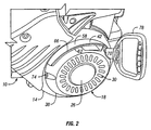
- Fig. 2 is an enlarged view of the engine having a rewind cover guard of Fig. 1.
- Fig. 3 is an enlarged view of the engine having a rewind cover guard of Fig. 1.
- Fig. 4 is an assembly view of the engine having a rewind cover guard of Fig. 1.
- Fig. 5 is a perspective view of the rewind cover guard embodying the invention.
- Fig. 6 is a plan view of the rewind cover guard of Fig. 5.
- Fig. 7 is a plan view of the rewind cover guard of Fig. 5.
- Figs. 1-4 illustrates an
internal combustion engine 10 having ablower housing 14 and astarter rewind cover 18. Theblower housing 14 encloses a fan and the air intake system of theengine 10. Theblower housing 14 has an intake opening 22 through which air passes as it enters theblower housing 14. Thestarter rewind cover 18 is disposed near theintake opening 22 and partially encloses the starter rewind mechanism. - The
engine 10 shown in Figs. 1-4 is a horizontal shaft engine with thestarter rewind cover 18 interconnected to the side of theblower housing 14. In the illustrated embodiment, therewind cover 18 has anouter face 26 that lies in a substantially vertical plane. Air entering theblower housing 14 passes throughapertures 30 in theouter face 26. Theapertures 30 are sized to permit adequate air flow into theblower housing 14, while helping to prevent relatively large objects or debris from entering theblower housing 14. - A
guard 34 is disposed adjacent theblower housing 14 andrewind starter 18. Theguard 34 includes amounting surface 38 and aflange 42. As shown in Fig. 5, themounting surface 38 is a generally ring shaped member having aninner edge 46 and anouter edge 50. In the illustrated embodiment, themounting surface 38 is arc-shaped to correspond to the shape of the intake opening 22 (Fig. 4) of theblower housing 14. However, themounting surface 38 could also have a multi-sided shape with theinner edge 46 andouter edge 50 comprised of several segments. Themounting surface 38 may have one ormore fastening apertures 54 spaced along themounting surface 38. - The
flange 42 is formed integral with themounting surface 38, and projects outwardly from themounting surface 38 in a generally axial direction. In the illustrated embodiment, theflange 42 projects in a direction transverse to themounting surface 38, although it could form various angles with themounting surface 38. Theflange 42 has a deflectingsurface 58 on the radially outward face of theflange 42. In the illustrations, thedeflecting surface 58 and theflange 42 correspond to the arc-shape of theouter edge 50. - The
flange 42 has afree edge 62 at the edge of theflange 42 opposite themounting surface 38, and alip 66 that is disposed near thefree edge 62. Thelip 66 is a slightly raised ridge that projects from thedeflecting surface 58 in a direction radially outward from themounting surface 38. Thelip 66 and the deflectingsurface 58 channel moisture away from the rewind cover 18 (Fig. 4) and intake opening 22 (Fig. 4). The illustrated embodiment of theflange 42 includes anindentation 70 near an end of theflange 42 where thefree edge 62 slants inward toward themounting surface 38. - Figs. 6 and 7 illustrate the
flange 42 projecting from themounting surface 38, as viewed from opposite sides of theguard 34. As shown in Figs. 6 and 7, thelip 66 projects from thedeflecting surface 58 near thefree edge 62. As mentioned above, thelip 66 helps direct the flow of moisture across thedeflecting surface 58 and away from the rewind cover 18 (Fig. 4) and intake opening 22 (Fig. 4). As shown in Fig. 7, theflange 42 includes anindentation 70 near an end of theflange 42. - As shown in Figs. 1-4, the
guard 34 is disposed near the interface of theblower housing 14 and therewind cover 18. Therewind cover 18 is coupled to theblower housing 14 withfasteners 74, such as screws, bolts, rivets, or other similar conventional fasteners. Themounting surface 38 is disposed between theblower housing 14 and therewind cover 18, and theflange 42 extends outward away from theblower housing 14. Therewind cover 18,blower housing 14, andguard 34 are aligned so thefasteners 66 pass through thefastening apertures 54 on themounting surface 38 before interconnecting to theblower housing 14. Theguard 42 is preferably made from a slightly deformable plastic material that may seal the interface between therewind cover 18 andblower housing 14. Themounting surface 38 may function as a gasket and generally improves the seal between therewind cover 18 and theblower housing 14. - As mentioned above, this invention may be used on snow thrower engines exposed to environments with large quantities of snow. The running temperature of the
engine 10 is above the melting point of snow, so snow that comes in contacts with theengine 10 will melt. Due to gravity, water or melted snow may run down the sides of theengine 10, and theguard 34 diverts the water away from therewind cover 18. In the illustrated embodiment, theflange 42 extends from at least a portion of themounting surface 38, and could completely encircle therewind cover 18. Theflange 42 is at least partially disposed above therewind cover 18, with the deflectingsurface 58 facing away from therewind cover 18. Water running down theengine 10 contacts the curveddeflecting surface 58 and is directed around the sides of therewind cover 18. Thelip 66 along thefree edge 62 of theflange 42 also diverts the water to the side of the rewind cover, and may prevent water from flowing over thefree edge 62 and onto therewind cover 18. - As shown in Figs. 1-4, a
handle 78 extends away from therewind cover 18. Thehandle 78 is attached to a pull cord that is used to start theengine 10 as part of a conventional pull cord starting mechanism. Theindentation 70 in theflange 42 provides clearance for thehandle 78 during operation of theengine 10, and for the pull cord when thehandle 78 is pulled during starting. - While several embodiments of the invention have been shown and described, alternate embodiments will be apparent to those skilled in the art and are within the intended scope of the following claims.
Claims (8)
- An internal combustion engine (10) comprising:a blower housing (14);a starter rewind cover (18) adjacent to the blower housing (14); and being characterized by a flange (42) disposed vertically above the starter rewind cover (18) that diverts moisture away from the starter rewind cover (18).
- The engine of claim 1, wherein the flange (42) extends from the blower housing (14) beyond the starter rewind cover (18).
- The engine of claim 1, wherein the flange (42) is substantially arc-shaped.
- The engine of claim 1, wherein the flange (42) further comprises:a free edge (62) disposed opposite the blower housing (14);a deflecting surface (58) on a face of the flange (42) opposite the starter rewind cover (18); anda lip (66) disposed along the free edge (62) that is raised from the deflecting surface (58) of the flange (42).
- The engine of claim 4, wherein the flange (42) has an indentation (70) in the free edge (62) that provides clearance for a pull cord and handle (78) that extend away from the starter rewind cover (18).
- The engine of claim 1, further comprising:a mounting portion (38) formed integral with the flange (42), wherein the mounting portion (38) is disposed between the blower housing (14) and the starter rewind cover (18), and wherein the flange (42) projects outwardly from the mounting portion (38).
- The engine of claim 6, wherein the mounting portion (38) substantially ring shaped and includes an inner edge and an outer edge, and wherein the flange (42) extends from the mounting portion (38) near the outer edge.
- The engine of claim 1, wherein the flange (42) extends in a direction substantially transverse to the starter rewind cover (18).
Applications Claiming Priority (5)
| Application Number | Priority Date | Filing Date | Title |
|---|---|---|---|
| US29822101P | 2001-06-14 | 2001-06-14 | |
| US298221P | 2001-06-14 | ||
| US154226 | 2002-05-23 | ||
| US10/154,226 US6520141B2 (en) | 2001-06-14 | 2002-05-23 | Rewind cover guard |
| PCT/US2002/018747 WO2002103175A1 (en) | 2001-06-14 | 2002-06-14 | Rewind cover guard |
Publications (2)
| Publication Number | Publication Date |
|---|---|
| EP1395740A1 EP1395740A1 (en) | 2004-03-10 |
| EP1395740B1 true EP1395740B1 (en) | 2006-10-04 |
Family
ID=26851262
Family Applications (1)
| Application Number | Title | Priority Date | Filing Date |
|---|---|---|---|
| EP02739869A Expired - Lifetime EP1395740B1 (en) | 2001-06-14 | 2002-06-14 | Rewind cover guard |
Country Status (4)
| Country | Link |
|---|---|
| US (1) | US6520141B2 (en) |
| EP (1) | EP1395740B1 (en) |
| DE (1) | DE60215160T2 (en) |
| WO (1) | WO2002103175A1 (en) |
Families Citing this family (16)
| Publication number | Priority date | Publication date | Assignee | Title |
|---|---|---|---|---|
| USD503723S1 (en) | 2004-02-16 | 2005-04-05 | Liquid Combustion Technology Llc | Portion of an engine |
| USD521024S1 (en) | 2004-02-16 | 2006-05-16 | Liquid Combustion Technology Llc | Portion of an engine |
| USD549241S1 (en) | 2004-08-11 | 2007-08-21 | Liquid Combustion Technology Llc | Portion of a recoil cover for an internal combustion engine |
| USD532794S1 (en) | 2004-08-16 | 2006-11-28 | Liquid Combustion Technology Llc | Portion of an internal combustion engine |
| USD540938S1 (en) * | 2006-07-10 | 2007-04-17 | R.W. Beckett Corporation | Igniter cover |
| USD573248S1 (en) * | 2006-12-13 | 2008-07-15 | R. W. Beckett Corporation | Burner controller cover |
| USD570879S1 (en) | 2007-01-05 | 2008-06-10 | Onihr Manufacturing Srl | Muffler housing |
| USD570877S1 (en) | 2007-01-05 | 2008-06-10 | Onihr Manufacturing Srl | Engine |
| USD576638S1 (en) * | 2007-09-21 | 2008-09-09 | Black & Decker Inc. | Engine |
| USD611411S1 (en) * | 2008-07-29 | 2010-03-09 | Wesley Harmelink | Engine recoil handle |
| USD610163S1 (en) | 2008-09-02 | 2010-02-16 | Wood Jeffery O | Engine |
| USD612402S1 (en) * | 2008-12-15 | 2010-03-23 | Loncin Industry Co., Ltd. | Internal-combustion engine |
| USD634333S1 (en) * | 2010-08-24 | 2011-03-15 | Briggs & Stratton Corporation | Engine |
| USD689522S1 (en) | 2011-08-26 | 2013-09-10 | Briggs & Stratton Corporation | Engine |
| USD671559S1 (en) * | 2011-10-13 | 2012-11-27 | Briggs & Stratton Corporation | Engine |
| USD749511S1 (en) | 2013-07-10 | 2016-02-16 | Champion Power Equipment, Inc. | Engine powered generator |
Family Cites Families (12)
| Publication number | Priority date | Publication date | Assignee | Title |
|---|---|---|---|---|
| US2741042A (en) * | 1951-07-25 | 1956-04-10 | Briggs & Stratton Corp | Snow plow with power driven rotor |
| US3465740A (en) * | 1968-02-13 | 1969-09-09 | Briggs & Stratton Corp | Pull rope type starter for vertical shaft engines |
| US3518979A (en) * | 1968-08-23 | 1970-07-07 | Briggs & Stratton Corp | Safety device for machine powered by small gas engine |
| US3583185A (en) * | 1969-11-03 | 1971-06-08 | Briggs & Stratton Corp | Key-controlled lock switch with reliable weather protection cover |
| US3871350A (en) * | 1971-07-29 | 1975-03-18 | Eaton Stamping Co | Recoil starter |
| US3779325A (en) | 1972-04-07 | 1973-12-18 | Valmet Oy | Motor guard |
| US3744468A (en) * | 1972-05-26 | 1973-07-10 | Briggs & Stratton Corp | Combined rope starter and guard for gasoline engines |
| US4211058A (en) | 1978-08-14 | 1980-07-08 | Outboard Marine Corporation | Lawn mower including a carburetor enclosure |
| US4995356A (en) | 1990-06-04 | 1991-02-26 | Tecumseh Products Company | Engine fuel tank shroud having dampened spring retainers |
| JP3591565B2 (en) | 1997-04-17 | 2004-11-24 | スズキ株式会社 | Intake device for internal combustion engine |
| US6381881B1 (en) | 1999-08-12 | 2002-05-07 | Murray, Inc. | Engine cover for a snow thrower |
| EP1079025A3 (en) | 1999-08-26 | 2002-08-28 | Tecumseh Products Company | Vertical shaft snow engine |
-
2002
- 2002-05-23 US US10/154,226 patent/US6520141B2/en not_active Expired - Fee Related
- 2002-06-14 WO PCT/US2002/018747 patent/WO2002103175A1/en not_active Ceased
- 2002-06-14 EP EP02739869A patent/EP1395740B1/en not_active Expired - Lifetime
- 2002-06-14 DE DE60215160T patent/DE60215160T2/en not_active Expired - Lifetime
Also Published As
| Publication number | Publication date |
|---|---|
| US6520141B2 (en) | 2003-02-18 |
| US20020189571A1 (en) | 2002-12-19 |
| EP1395740A1 (en) | 2004-03-10 |
| WO2002103175A1 (en) | 2002-12-27 |
| DE60215160D1 (en) | 2006-11-16 |
| DE60215160T2 (en) | 2007-10-18 |
Similar Documents
| Publication | Publication Date | Title |
|---|---|---|
| US6520141B2 (en) | Rewind cover guard | |
| US5857329A (en) | One-piece combined muffler exhaust outlet and exhaust gas deflector | |
| US6779989B2 (en) | Method for connecting compressor with built-in electric motor and external wiring, connection device used therefor, and compressor with built-in electric motor using the same | |
| US7316596B2 (en) | Outboard motor | |
| EP1893850B1 (en) | Turbocharger intake air chamber provided with air inlet from crankcase blowby ventilation (ccv) | |
| WO1996030642A1 (en) | Integrated dynamic air cleaner | |
| WO1999011929A3 (en) | Piston compressor for refrigerant, with thermal insulation | |
| US4716326A (en) | Electric motor with adjustable switch location | |
| GB2297806A (en) | Water pump for internal combustion engines | |
| US4086507A (en) | Outdoor motor enclosure | |
| FR2827345A1 (en) | Motor fan unit with integrated control card for cooling engine for road vehicle has input and output openings arranged so that cooling airflow sweeps over card components | |
| CN1261650A (en) | Outdoor machine power cover device for split air conditioner | |
| US5438825A (en) | Air-cooled engine for powering portable equipment | |
| JP3424027B2 (en) | Foreign matter suction prevention member for air-cooled internal combustion engine | |
| JP3322076B2 (en) | Mounting structure of crank angle sensor | |
| CN210720990U (en) | Lens splash-proof device and optical remote sensing equipment | |
| EP1079025A2 (en) | Vertical shaft snow engine | |
| CN215333083U (en) | Novel fan cover protection device | |
| JP4682124B2 (en) | Air-cooled V-type engine | |
| KR950004780Y1 (en) | Bathroom Vents | |
| CN222478844U (en) | Engine starter cover body and engine | |
| CN212106030U (en) | Fan housing of automobile cooling fan | |
| JPS5928086Y2 (en) | forced air cooled engine | |
| CN221374388U (en) | Speed reducer for coal mining machine | |
| JPH0229224Y2 (en) |
Legal Events
| Date | Code | Title | Description |
|---|---|---|---|
| PUAI | Public reference made under article 153(3) epc to a published international application that has entered the european phase |
Free format text: ORIGINAL CODE: 0009012 |
|
| 17P | Request for examination filed |
Effective date: 20030220 |
|
| AK | Designated contracting states |
Kind code of ref document: A1 Designated state(s): AT BE CH CY DE DK ES FI FR GB GR IE IT LI LU MC NL PT SE TR |
|
| GRAP | Despatch of communication of intention to grant a patent |
Free format text: ORIGINAL CODE: EPIDOSNIGR1 |
|
| RBV | Designated contracting states (corrected) |
Designated state(s): DE FR GB IT |
|
| GRAS | Grant fee paid |
Free format text: ORIGINAL CODE: EPIDOSNIGR3 |
|
| GRAA | (expected) grant |
Free format text: ORIGINAL CODE: 0009210 |
|
| AK | Designated contracting states |
Kind code of ref document: B1 Designated state(s): DE FR GB IT |
|
| PG25 | Lapsed in a contracting state [announced via postgrant information from national office to epo] |
Ref country code: IT Free format text: LAPSE BECAUSE OF FAILURE TO SUBMIT A TRANSLATION OF THE DESCRIPTION OR TO PAY THE FEE WITHIN THE PRESCRIBED TIME-LIMIT;WARNING: LAPSES OF ITALIAN PATENTS WITH EFFECTIVE DATE BEFORE 2007 MAY HAVE OCCURRED AT ANY TIME BEFORE 2007. THE CORRECT EFFECTIVE DATE MAY BE DIFFERENT FROM THE ONE RECORDED. Effective date: 20061004 |
|
| REG | Reference to a national code |
Ref country code: GB Ref legal event code: FG4D |
|
| REF | Corresponds to: |
Ref document number: 60215160 Country of ref document: DE Date of ref document: 20061116 Kind code of ref document: P |
|
| EN | Fr: translation not filed | ||
| PLBE | No opposition filed within time limit |
Free format text: ORIGINAL CODE: 0009261 |
|
| STAA | Information on the status of an ep patent application or granted ep patent |
Free format text: STATUS: NO OPPOSITION FILED WITHIN TIME LIMIT |
|
| 26N | No opposition filed |
Effective date: 20070705 |
|
| PG25 | Lapsed in a contracting state [announced via postgrant information from national office to epo] |
Ref country code: FR Free format text: LAPSE BECAUSE OF FAILURE TO SUBMIT A TRANSLATION OF THE DESCRIPTION OR TO PAY THE FEE WITHIN THE PRESCRIBED TIME-LIMIT Effective date: 20070525 |
|
| PG25 | Lapsed in a contracting state [announced via postgrant information from national office to epo] |
Ref country code: FR Free format text: LAPSE BECAUSE OF FAILURE TO SUBMIT A TRANSLATION OF THE DESCRIPTION OR TO PAY THE FEE WITHIN THE PRESCRIBED TIME-LIMIT Effective date: 20061004 |
|
| PGFP | Annual fee paid to national office [announced via postgrant information from national office to epo] |
Ref country code: GB Payment date: 20110608 Year of fee payment: 10 |
|
| PGFP | Annual fee paid to national office [announced via postgrant information from national office to epo] |
Ref country code: DE Payment date: 20120607 Year of fee payment: 11 |
|
| GBPC | Gb: european patent ceased through non-payment of renewal fee |
Effective date: 20120614 |
|
| PG25 | Lapsed in a contracting state [announced via postgrant information from national office to epo] |
Ref country code: GB Free format text: LAPSE BECAUSE OF NON-PAYMENT OF DUE FEES Effective date: 20120614 |
|
| REG | Reference to a national code |
Ref country code: DE Ref legal event code: R119 Ref document number: 60215160 Country of ref document: DE Effective date: 20140101 |
|
| PG25 | Lapsed in a contracting state [announced via postgrant information from national office to epo] |
Ref country code: DE Free format text: LAPSE BECAUSE OF NON-PAYMENT OF DUE FEES Effective date: 20140101 |