EP1395021A1 - Portable radio unit - Google Patents
Portable radio unit Download PDFInfo
- Publication number
- EP1395021A1 EP1395021A1 EP02705090A EP02705090A EP1395021A1 EP 1395021 A1 EP1395021 A1 EP 1395021A1 EP 02705090 A EP02705090 A EP 02705090A EP 02705090 A EP02705090 A EP 02705090A EP 1395021 A1 EP1395021 A1 EP 1395021A1
- Authority
- EP
- European Patent Office
- Prior art keywords
- housing
- antenna
- built
- user
- receiver
- Prior art date
- Legal status (The legal status is an assumption and is not a legal conclusion. Google has not performed a legal analysis and makes no representation as to the accuracy of the status listed.)
- Withdrawn
Links
Images

Classifications
-
- H—ELECTRICITY
- H04—ELECTRIC COMMUNICATION TECHNIQUE
- H04M—TELEPHONIC COMMUNICATION
- H04M1/00—Substation equipment, e.g. for use by subscribers
- H04M1/02—Constructional features of telephone sets
- H04M1/0202—Portable telephone sets, e.g. cordless phones, mobile phones or bar type handsets
- H04M1/0279—Improving the user comfort or ergonomics
-
- H—ELECTRICITY
- H01—ELECTRIC ELEMENTS
- H01Q—ANTENNAS, i.e. RADIO AERIALS
- H01Q1/00—Details of, or arrangements associated with, antennas
- H01Q1/12—Supports; Mounting means
- H01Q1/22—Supports; Mounting means by structural association with other equipment or articles
- H01Q1/24—Supports; Mounting means by structural association with other equipment or articles with receiving set
- H01Q1/241—Supports; Mounting means by structural association with other equipment or articles with receiving set used in mobile communications, e.g. GSM
- H01Q1/242—Supports; Mounting means by structural association with other equipment or articles with receiving set used in mobile communications, e.g. GSM specially adapted for hand-held use
- H01Q1/243—Supports; Mounting means by structural association with other equipment or articles with receiving set used in mobile communications, e.g. GSM specially adapted for hand-held use with built-in antennas
-
- H—ELECTRICITY
- H01—ELECTRIC ELEMENTS
- H01Q—ANTENNAS, i.e. RADIO AERIALS
- H01Q1/00—Details of, or arrangements associated with, antennas
- H01Q1/12—Supports; Mounting means
- H01Q1/22—Supports; Mounting means by structural association with other equipment or articles
- H01Q1/24—Supports; Mounting means by structural association with other equipment or articles with receiving set
- H01Q1/241—Supports; Mounting means by structural association with other equipment or articles with receiving set used in mobile communications, e.g. GSM
- H01Q1/242—Supports; Mounting means by structural association with other equipment or articles with receiving set used in mobile communications, e.g. GSM specially adapted for hand-held use
- H01Q1/245—Supports; Mounting means by structural association with other equipment or articles with receiving set used in mobile communications, e.g. GSM specially adapted for hand-held use with means for shaping the antenna pattern, e.g. in order to protect user against rf exposure
-
- H—ELECTRICITY
- H04—ELECTRIC COMMUNICATION TECHNIQUE
- H04B—TRANSMISSION
- H04B1/00—Details of transmission systems, not covered by a single one of groups H04B3/00 - H04B13/00; Details of transmission systems not characterised by the medium used for transmission
- H04B1/38—Transceivers, i.e. devices in which transmitter and receiver form a structural unit and in which at least one part is used for functions of transmitting and receiving
- H04B1/3827—Portable transceivers
- H04B1/3833—Hand-held transceivers
Definitions
- the present invention relates to a cellular phone, a portable terminal unit and other portable wireless apparatus having a built-in antenna.
- a portable wireless apparatus for example, a cellular phone is provided with a transmitter and receiver which are respectively arranged at both end portions of a housing on the surface side.
- a region which is a half of the surface of the housing on the side on which the transmitter is arranged this region will be referred to as a lower half region hereinafter, various key switches used for operation are arranged.
- this region will be referred to as an upper half region hereinafter, an image display section is arranged.
- the cellular phone composed as described above for example, when a user inputs the telephone number of an opponent, the user conducts inputting operation in many cases while holding the housing of the cellular.phone with the palm of one of his hands.
- the present invention has been accomplished to solve the above conventional problems. It is an object of the present invention to provide a portable wireless apparatus characterized in that: a housing can be stably held with the user's hand; and.even if it is not clear for the user where a built-in antenna is arranged in the housing, the apparatus is composed so that the user's fingers holding the housing can not carelessly come into close-contact with the portion of the housing in which the built-in antenna is arranged.
- the present invention provides a portable wireless apparatus comprising: a transmitter arranged at one end portion of a housing; a receiver arranged at the other end portion of the housing; and a recess portion, in which a user's finger tip to hold the housing is put, arranged on the rear side of the housing with respect to the surface side on which the transmitter and receiver are arranged, in a portion opposed to the receiver or in a portion on the transmitter side of the portion opposed to the receiver.
- the present invention also provides a portable wireless apparatus comprising: a transmitter arranged at one end portion of a housing; a receiver arranged at the other end portion of the housing; a built-in antenna arranged close to the receiver in the housing; and a recess portion to be used as an index for preventing a user' s finger to hold the housing from being located in a portion where 'the built-in antenna is arranged when the user holds the housing so as to use the' wireless apparatus, arranged on the receiver side with respect to the portion where the built-in antenna is arranged.
- the housing when a user holds the housing with his hand, at least one of the fingers of the hand is put in the recess provided in the portion opposed to the receiver on the rear face of the housing or provided in a portion close to the portion opposed to the receiver on the rear face of the housing, and then the housing can be stably held.
- the portion in which the built-in antenna is provided can be easily prevented from being covered with the user's hand or finger to hold the housing. Therefore, transmission and reception can be conducted at high sensitivity without deteriorating sensitivity of the built-in antenna.
- reference marks in the drawings represent components as follows.
- Reference mark 1a is a housing on the front side
- reference mark 1b is a housing on the rear side
- reference mark 1c is a recess portion
- reference mark 2 is an accommodating section
- reference mark 3 is a battery
- reference mark 4a is a transmitter
- reference mark 4b is a receiver
- reference mark 5 is a connector used for data communication
- reference mark 6 is a printed board
- reference mark 7 is a keyboard
- reference mark 8 is a liquid crystal display
- reference mark 9 is a built-in antenna
- reference mark 11 is a speaker
- reference mark 12 is a display means.
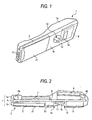
- FIG. 1 is a perspective view showing a rear face of the portable wireless apparatus of the present invention
- Fig. 2 is a sectional side view showing an outline of the portable wireless apparatus
- Fig. 3 is a view showing a state in which the portable wireless apparatus is used.
- a cellular phone is assumed to be the portable wireless apparatus.
- the portable wireless apparatus is not limited to a cellular phone. As long.as it is a portable terminal unit capable of communicating by wireless, any portable terminal unit can be used as the portable wireless apparatus.
- the housing 1 is composed of a front side housing 1a and rear side housing 1b.
- the front side housing 1a includes: a through-hole for the keyboard 7; a window through' which the liquid crystal display 8 is seen; a sound hole for the transmitter; and a sound hole for the receiver.
- a battery accommodating section 2 In the rear side housing 1b, there is provided a battery accommodating section 2.
- the cover 21 having the battery 3 is detachably attached to this battery accommodating section 2.
- the transmitter 4a and the receiver 4b are respectively built in.
- a connector 5 used for data communication.
- a printed board 6 On the front side of the printed board 6, in a portion close to the transmitter 4a, there is provided a keyboard 7. On the front side of the printed board 6, in a portion close to the receiver 4b, there is provided a liquid crystal display 8. On the rear side of the printer board 6, there are provided various electric parts 13. On the rear side of the printed board 6, in a portion close to the receiver 4b, there is provided a plate-shaped built-in antenna 9.
- a speaker 11 On the side close to the transmitter 4a with respect to the built-in antenna 9, there is provided a speaker 11 to generate a ringing tone.
- a recess portion 1c In a portion of the rear side housing 1b opposed to the speaker 11, there is provided a recess portion 1c, which becomes an index to position a hand or finger for holding the housing 1 when the portable wireless apparatus is used so that the built-in antenna 9 can not be covered with the hand or finger.
- the size of this recess portion 1c is determined so that a finger tip of a user can be put into the recess 1c, usually, the forefinger can be put into the recess 1c.
- the size of this recess portion 1c is determined to be a little larger than the size in which the forefinger can be put into the recess 1c.
- the recess portion 1c is formed into an accurate circle or an ellipse. Concerning the profile of this recess portion 1c, as shown in Fig. 2, in order for the user to easily put his finger from the lower side of the housing 1 into the recess, the inclination of the lower side face 1e is made to be smaller than that of the upper side face 1f.
- a sound hole 1d from which a sound of the speaker 11 is emitted.
- a display means 12 which is an index displaying that the built-in antenna exists in this portion.
- this display means 12 for example, there is an explanation "Antenna is arranged here", or alternatively there is a caution "Don't cover this portion with your hand because the antenna is arranged here".
- the built-in antenna 9 is arranged in a portion of the housing 1 close to the receiver 4b. Accordingly, in the case where the housing 1 is held so as to use the wireless apparatus, since the side'opposite to the side on which the built-in antenna 9 is arranged is usually held by the user, that is, the side on which the transmitter 4a is arranged is held, that is, a portion of the housing 1 where the keyboard is arranged is held. Accordingly, there is a small possibility that a hand or finger to hold the housing 1 comes close to the portion where the built-in antenna 9 is arranged.
- a recess portion 1c which becomes an index to be used so that a hand or finger to hold the housing 1 can not be located in a portion of the housing 1 opposed to the built-in antenna 9. Therefore, due to the above index, the hand or finger to hold the housing 1 can not be located in a portion where the built-in antenna is arranged.
- the forefinger is inserted into the recess portion 1c and the other fingers hold the housing 1. Then, no hand or finger is located in the portion where the built-in antenna 9 is arranged. Accordingly, a chance of the deterioration of sensitivity of the built-in antenna 9 caused by the approach of the hand or finger to the built-in antenna 9 can be reduced as small as possible.
- the recess portion 1c is opposed to the speaker 11, and the sound hole 1d is formed on the bottom face of the recess portion 1c. Therefore, the sound hole 1d is not blocked in the waiting time of the wireless apparatus, and a ringing sound can be effectively emitted from the speaker.
- the housing 1 Since the housing 1 is made thin, the other electronic parts are not attached at the position where the speaker 11 is arranged. Accordingly, a gap can be easily formed in this portion inside the housing 1. Therefore, this structure is advantageous in that the recess portion 1c can be effectively formed by utilizing this gap.
- the display means 12 for displaying that the built-in antenna 9 exists at the position is arranged in a portion of the housing 1 where the built-in antenna 9 is located. Therefore, it is possible for a user to hold the housing 1 while evading the portion where the built-in antenna 9 is located while fixing the user's aim at this display means 12. In this way, the built-in antenna 9 is not affected by the hand or finger to hold the housing 1.
- the recess portion 1c in order to prevent the built-in antenna 9 from being covered with the hand or finger, the recess portion 1c is provided.
- the position where the built-in antenna 9 is arranged is not limited to this specific position. In this case, if this recess portion is provided in a portion of the rear side housing opposed to the receiver or in a portion closer to the transmitter than this portion, at least one of the fingers of the hand to hold the housing 1 is inserted into this recess portion. Due to the foregoing, the housing can be more stably held.
- a portable wireless apparatus comprising: a transmitter arranged at one end portion of a housing; a receiver arranged at the other end portion of the housing; and a recess portion, in which a user's finger tip to hold the housing is put, arranged on the rear side of the housing with respect to the surface side on which the transmitter and receiver are arranged, in a portion opposed to the receiver or in a portion on the transmitter side of the portion opposed to the receiver. Therefore, when a finger is inserted into this recess portion, the housing can be held by this recess portion. Accordingly, the housing can be held stably.
- the built-in antenna is arranged on the side close to the receiver of the housing, and on the side of the built-in antenna close to the transmitter, there is provided a recess portion which becomes an index to be used so that a hand or finger to hold the housing can not be located in a portion opposed to the built-in antenna when the wireless apparatus is used while a user is holding the housing. Therefore, when the housing is held by utilizing this recess portion, even if it is not clear for the user where the built-in antenna is located in the housing, it is possible to prevent the user from coming into contact with the portion, in which the built-in antenna is located, with his hand or finger. Therefore, it is possible to provide an effect that transmission and reception can be conducted with high sensitivity at all times without deteriorating sensitivity of the built-in antenna.
- the built-in antenna can not be affected by the user's hand or finger when the finger or hand to hold the housing is kept at a distance from the portion.
Landscapes
- Engineering & Computer Science (AREA)
- Computer Networks & Wireless Communication (AREA)
- Signal Processing (AREA)
- Telephone Set Structure (AREA)
- Support Of Aerials (AREA)
- Transceivers (AREA)
- Casings For Electric Apparatus (AREA)
Abstract
A task of the present invention is to stably hold a
housing. Another task of the present invention is to
prevent a user from carelessly approaching a portion of the
housing, in which a built-in antenna is located, with his
hand or finger even if where the portion is located is not
clear for the user.
The present invention provides a portable wireless
apparatus comprising: a transmitter 4a arranged at one end
portion of a housing 1; a receiver 4b arranged at the other
end portion of the housing 1; a built-in antenna 8 arranged
close to the receiver 4b in the housing 1; and a recess
portion 1c to be used as an index for preventing a user's
finger to hold the housing 1 from being positioned in a
portion where the built-in antenna 9 is arranged when the
user holds the housing 1 so as to use the wireless
apparatus, arranged on the receiver 4b side with respect to
the portion where the built-in antenna 9 is arranged.
Description
- The present invention relates to a cellular phone, a portable terminal unit and other portable wireless apparatus having a built-in antenna.
- A portable wireless apparatus, for example, a cellular phone is provided with a transmitter and receiver which are respectively arranged at both end portions of a housing on the surface side. In a region which is a half of the surface of the housing on the side on which the transmitter is arranged, this region will be referred to as a lower half region hereinafter, various key switches used for operation are arranged. On the other hand, in a residual region which is a half of the surface of the housing on the side on which the receiver is arranged, this region will be referred to as an upper half region hereinafter, an image display section is arranged.
- In the case of the cellular phone composed as described above, for example, when a user inputs the telephone number of an opponent, the user conducts inputting operation in many cases while holding the housing of the cellular.phone with the palm of one of his hands.
- However, in the case where inputting operation is conducted on the key switches by the user while holding the housing with one of his hands, the user tends to hold only a lower half region of the housing in which the key switches are arranged. Therefore, inputting operation can not be stably conducted in many cases. Further, for example, when the user communicates with an opponent on the telephone, the user tends to hold only a lower half region on the rear side of the housing. Accordingly, the receiver on the surface side of the housing can not be closely contacted with the user's ear, and it is impossible for the user to clearly listen to voices of the opponent in many cases.
- Most of the conventional cellular phones are provided with a rod-shaped antenna protruding outside of the housing. Recently, there has been a tendency that the rod-shaped antenna is not used because sensitivity of the electronic device is enhanced and further performance of the antenna is enhanced. As a result, the rod-shaped antenna is not used but only a plate-shaped built-in antenna is used in many cases.
- However, in this type cellular phone, it is impossible for the user to detect from the outside of the housing where the built-in antenna is arranged in the housing. Accordingly, when the user uses the cellular phone while holding the housing with one of the hands, the user's finger tends to cower a portion where the built-in antenna is built in. Accordingly, there is a high possibility that sensitivity of the built-in antenna is remarkably deteriorated.
- The present invention has been accomplished to solve the above conventional problems. It is an object of the present invention to provide a portable wireless apparatus characterized in that: a housing can be stably held with the user's hand; and.even if it is not clear for the user where a built-in antenna is arranged in the housing, the apparatus is composed so that the user's fingers holding the housing can not carelessly come into close-contact with the portion of the housing in which the built-in antenna is arranged.
- In order to accomplish the above object, the present invention provides a portable wireless apparatus comprising: a transmitter arranged at one end portion of a housing; a receiver arranged at the other end portion of the housing; and a recess portion, in which a user's finger tip to hold the housing is put, arranged on the rear side of the housing with respect to the surface side on which the transmitter and receiver are arranged, in a portion opposed to the receiver or in a portion on the transmitter side of the portion opposed to the receiver.
- The present invention also provides a portable wireless apparatus comprising: a transmitter arranged at one end portion of a housing; a receiver arranged at the other end portion of the housing; a built-in antenna arranged close to the receiver in the housing; and a recess portion to be used as an index for preventing a user' s finger to hold the housing from being located in a portion where 'the built-in antenna is arranged when the user holds the housing so as to use the' wireless apparatus, arranged on the receiver side with respect to the portion where the built-in antenna is arranged.
- Therefore, according to the present invention, when a user holds the housing with his hand, at least one of the fingers of the hand is put in the recess provided in the portion opposed to the receiver on the rear face of the housing or provided in a portion close to the portion opposed to the receiver on the rear face of the housing, and then the housing can be stably held.
- According to the present invention, the portion in which the built-in antenna is provided can be easily prevented from being covered with the user's hand or finger to hold the housing. Therefore, transmission and reception can be conducted at high sensitivity without deteriorating sensitivity of the built-in antenna.
- In the drawings:
- Fig. 1 is a perspective view showing a cellular phone relating to the present invention;
- Fig. 2 is an arrangement view showing an outline of the section of the cellular phone shown in Fig. 1; and
- Fig. 3 is a schematic illustration showing a state in which the cellular phone is used.
-
- In this connection, reference marks in the drawings represent components as follows.
Reference mark 1a is a housing on the front side,reference mark 1b is a housing on the rear side,reference mark 1c is a recess portion,reference mark 2 is an accommodating section, reference mark 3 is a battery,reference mark 4a is a transmitter,reference mark 4b is a receiver,reference mark 5 is a connector used for data communication,reference mark 6 is a printed board,reference mark 7 is a keyboard, reference mark 8 is a liquid crystal display,reference mark 9 is a built-in antenna,reference mark 11 is a speaker andreference mark 12 is a display means. - Referring to the accompanying drawings, an embodiment of the present invention will be explained below.
- The drawings show an embodiment of the portable wireless apparatus relating to the present invention. Fig. 1 is a perspective view showing a rear face of the portable wireless apparatus of the present invention, Fig. 2 is a sectional side view showing an outline of the portable wireless apparatus, and.Fig. 3 is a view showing a state in which the portable wireless apparatus is used. In the above embodiment, a cellular phone is assumed to be the portable wireless apparatus. However, it should be noted that the portable wireless apparatus is not limited to a cellular phone. As long.as it is a portable terminal unit capable of communicating by wireless, any portable terminal unit can be used as the portable wireless apparatus.
- In Figs. 1 and 2, the
housing 1 is composed of afront side housing 1a andrear side housing 1b. Although not shown in the drawing, thefront side housing 1a includes: a through-hole for thekeyboard 7; a window through' which the liquid crystal display 8 is seen; a sound hole for the transmitter; and a sound hole for the receiver. - In the
rear side housing 1b, there is provided abattery accommodating section 2. Thecover 21 having the battery 3 is detachably attached to thisbattery accommodating section 2. At both end portions of thehousing 1 composed of thefront side housing 1a and therear side housing 1b, thetransmitter 4a and thereceiver 4b are respectively built in. At the end portion of thehousing 1 in which thetransmitter 4a is arranged, there is provided aconnector 5 used for data communication. - In the
housing 1, there is provided a printedboard 6. On the front side of the printedboard 6, in a portion close to thetransmitter 4a, there is provided akeyboard 7. On the front side of the printedboard 6, in a portion close to thereceiver 4b, there is provided a liquid crystal display 8. On the rear side of theprinter board 6, there are provided variouselectric parts 13. On the rear side of the printedboard 6, in a portion close to thereceiver 4b, there is provided a plate-shaped built-inantenna 9. - On the side close to the
transmitter 4a with respect to the built-inantenna 9, there is provided aspeaker 11 to generate a ringing tone. In a portion of therear side housing 1b opposed to thespeaker 11, there is provided arecess portion 1c, which becomes an index to position a hand or finger for holding thehousing 1 when the portable wireless apparatus is used so that the built-in antenna 9 can not be covered with the hand or finger. - Therefore, the size of this
recess portion 1c is determined so that a finger tip of a user can be put into therecess 1c, usually, the forefinger can be put into therecess 1c. Alternatively, the size of thisrecess portion 1c is determined to be a little larger than the size in which the forefinger can be put into therecess 1c. In order to make the user easily put his finger into therecess portion 1c, for example, therecess portion 1c is formed into an accurate circle or an ellipse. Concerning the profile of thisrecess portion 1c, as shown in Fig. 2, in order for the user to easily put his finger from the lower side of thehousing 1 into the recess, the inclination of thelower side face 1e is made to be smaller than that of theupper side face 1f. - On the bottom face of the
recess portion 1c, there is provided asound hole 1d from which a sound of thespeaker 11 is emitted. In one of the front side housing and the rear side housing, which are opposed to the built-inantenna 9, there is provided a display means 12 which is an index displaying that the built-in antenna exists in this portion. In this display means 12, for example, there is an explanation "Antenna is arranged here", or alternatively there is a caution "Don't cover this portion with your hand because the antenna is arranged here". - As explained above, in the above embodiment, the built-
in antenna 9 is arranged in a portion of thehousing 1 close to thereceiver 4b. Accordingly, in the case where thehousing 1 is held so as to use the wireless apparatus, since the side'opposite to the side on which the built-inantenna 9 is arranged is usually held by the user, that is, the side on which thetransmitter 4a is arranged is held, that is, a portion of thehousing 1 where the keyboard is arranged is held. Accordingly, there is a small possibility that a hand or finger to hold thehousing 1 comes close to the portion where the built-inantenna 9 is arranged. - In the above embodiment, in a portion of the'
housing 1 on the side close to thetransmitter 4a with respect to the built-inantenna 9, there is provided arecess portion 1c which becomes an index to be used so that a hand or finger to hold thehousing 1 can not be located in a portion of thehousing 1 opposed to the built-inantenna 9. Therefore, due to the above index, the hand or finger to hold thehousing 1 can not be located in a portion where the built-in antenna is arranged. - In other words, in the case where the wireless apparatus is used while a user is holding the
housing 1, as shown in Fig. 3, the forefinger is inserted into therecess portion 1c and the other fingers hold thehousing 1. Then, no hand or finger is located in the portion where the built-inantenna 9 is arranged. Accordingly, a chance of the deterioration of sensitivity of the built-inantenna 9 caused by the approach of the hand or finger to the built-inantenna 9 can be reduced as small as possible. - Further, in the above embodiment, the
recess portion 1c is opposed to thespeaker 11, and thesound hole 1d is formed on the bottom face of therecess portion 1c. Therefore, thesound hole 1d is not blocked in the waiting time of the wireless apparatus, and a ringing sound can be effectively emitted from the speaker. - Since the
housing 1 is made thin, the other electronic parts are not attached at the position where thespeaker 11 is arranged. Accordingly, a gap can be easily formed in this portion inside thehousing 1. Therefore, this structure is advantageous in that therecess portion 1c can be effectively formed by utilizing this gap. - In the above embodiment, the display means 12 for displaying that the built-in
antenna 9 exists at the position is arranged in a portion of thehousing 1 where the built-inantenna 9 is located. Therefore, it is possible for a user to hold thehousing 1 while evading the portion where the built-inantenna 9 is located while fixing the user's aim at this display means 12. In this way, the built-inantenna 9 is not affected by the hand or finger to hold thehousing 1. - In this connection, in this embodiment, in order to prevent the built-in
antenna 9 from being covered with the hand or finger, therecess portion 1c is provided. However, it should be noted that the position where the built-inantenna 9 is arranged is not limited to this specific position. In this case, if this recess portion is provided in a portion of the rear side housing opposed to the receiver or in a portion closer to the transmitter than this portion, at least one of the fingers of the hand to hold thehousing 1 is inserted into this recess portion. Due to the foregoing, the housing can be more stably held. - In this connection, this application is based on Japanese Patent Application No. 2001-174133 filed on June 8, 2001. The content of the above Japanese Patent Application is taken in as a reference.
- As explained above, according to the present invention, there is provided a portable wireless apparatus comprising: a transmitter arranged at one end portion of a housing; a receiver arranged at the other end portion of the housing; and a recess portion, in which a user's finger tip to hold the housing is put, arranged on the rear side of the housing with respect to the surface side on which the transmitter and receiver are arranged, in a portion opposed to the receiver or in a portion on the transmitter side of the portion opposed to the receiver. Therefore, when a finger is inserted into this recess portion, the housing can be held by this recess portion.. Accordingly, the housing can be held stably.
- According to the present invention, the built-in antenna is arranged on the side close to the receiver of the housing, and on the side of the built-in antenna close to the transmitter, there is provided a recess portion which becomes an index to be used so that a hand or finger to hold the housing can not be located in a portion opposed to the built-in antenna when the wireless apparatus is used while a user is holding the housing. Therefore, when the housing is held by utilizing this recess portion, even if it is not clear for the user where the built-in antenna is located in the housing, it is possible to prevent the user from coming into contact with the portion, in which the built-in antenna is located, with his hand or finger. Therefore, it is possible to provide an effect that transmission and reception can be conducted with high sensitivity at all times without deteriorating sensitivity of the built-in antenna.
- As shown in the embodiment, in the case where an index to indicate the portion of the housing, in which the built-in antenna is located, is provided, it is possible for the user to hold the housing while fixing the user's aim at this index. Accordingly, the built-in antenna can not be affected by the user's hand or finger when the finger or hand to hold the housing is kept at a distance from the portion.
Claims (4)
- A portable wireless apparatus comprising:a transmitter arranged at one end portion of a housing;a receiver arranged at the other end portion of the housing; anda recess portion, in which a user's finger tip to hold the housing is put, arranged on the rear side of the housing with respect to the surface side on which the transmitter and receiver are arranged, in a portion opposed to the receiver or in a portion on the transmitter side of the portion opposed to the receiver.
- A portable wireless apparatus comprising:a transmitter arranged at one end portion of a housing;a receiver arranged at the other end portion of the housing;a built-in antenna arranged close to the receiver in the housing; anda recess portion to be used as an index for preventing a user's finger to hold the housing from being located in a portion where the built-in antenna is arranged when the user holds the housing so as to use the wireless apparatus, arranged on the receiver side with respect to the portion where the built-in antenna is arranged.
- A portable wireless apparatus according to claim 1 or 2, further comprising: a speaker for generating a ringing sound arranged in a portion inside the housing opposed to the recess portion; and a sound hole formed in a bottom portion of the recess portion.
- A portable wireless apparatus according to claim 1 or 2, further comprising: a display means for describing an explanation to inform the user of existence of the antenna, arranged in a portion of the housing opposed to the built-in antenna or describing a caution to prohibit the portion from being covered with the user's hand.
Applications Claiming Priority (3)
| Application Number | Priority Date | Filing Date | Title |
|---|---|---|---|
| JP2001174133 | 2001-06-08 | ||
| JP2001174133A JP2002368853A (en) | 2001-06-08 | 2001-06-08 | Portable wireless devices |
| PCT/JP2002/002145 WO2002102034A1 (en) | 2001-06-08 | 2002-03-07 | Portable radio unit |
Publications (1)
| Publication Number | Publication Date |
|---|---|
| EP1395021A1 true EP1395021A1 (en) | 2004-03-03 |
Family
ID=19015463
Family Applications (1)
| Application Number | Title | Priority Date | Filing Date |
|---|---|---|---|
| EP02705090A Withdrawn EP1395021A1 (en) | 2001-06-08 | 2002-03-07 | Portable radio unit |
Country Status (5)
| Country | Link |
|---|---|
| US (1) | US20030186728A1 (en) |
| EP (1) | EP1395021A1 (en) |
| JP (1) | JP2002368853A (en) |
| CN (1) | CN1215692C (en) |
| WO (1) | WO2002102034A1 (en) |
Families Citing this family (30)
| Publication number | Priority date | Publication date | Assignee | Title |
|---|---|---|---|---|
| USD496355S1 (en) | 2003-03-10 | 2004-09-21 | Motorola, Inc. | Portion of a housing for a communication device |
| EP1811750A4 (en) * | 2004-11-09 | 2009-07-08 | Sharp Kk | Portable information terminal |
| KR20070075154A (en) * | 2006-01-12 | 2007-07-18 | 엘지전자 주식회사 | Mobile communication terminal |
| US7778678B2 (en) * | 2006-10-10 | 2010-08-17 | Panasonic Corporation | Radio control device |
| JP5033532B2 (en) * | 2007-07-30 | 2012-09-26 | 京セラ株式会社 | Communication terminal |
| US8892049B2 (en) * | 2007-10-10 | 2014-11-18 | Apple Inc. | Handheld electronic devices with antenna power monitoring |
| US8417296B2 (en) * | 2008-06-05 | 2013-04-09 | Apple Inc. | Electronic device with proximity-based radio power control |
| US8432322B2 (en) | 2009-07-17 | 2013-04-30 | Apple Inc. | Electronic devices with capacitive proximity sensors for proximity-based radio-frequency power control |
| US8466839B2 (en) * | 2009-07-17 | 2013-06-18 | Apple Inc. | Electronic devices with parasitic antenna resonating elements that reduce near field radiation |
| WO2011017559A2 (en) * | 2009-08-05 | 2011-02-10 | Brinton Services, Inc. | Media player and peripheral devices therefore |
| US8781420B2 (en) | 2010-04-13 | 2014-07-15 | Apple Inc. | Adjustable wireless circuitry with antenna-based proximity detector |
| US8577289B2 (en) | 2011-02-17 | 2013-11-05 | Apple Inc. | Antenna with integrated proximity sensor for proximity-based radio-frequency power control |
| JP5847637B2 (en) * | 2012-04-12 | 2016-01-27 | 京セラ株式会社 | Electronics |
| US9093745B2 (en) | 2012-05-10 | 2015-07-28 | Apple Inc. | Antenna and proximity sensor structures having printed circuit and dielectric carrier layers |
| KR101666327B1 (en) * | 2012-08-20 | 2016-10-13 | 노키아 테크놀로지스 오와이 | Antenna apparatus and method of making same |
| US9300342B2 (en) | 2013-04-18 | 2016-03-29 | Apple Inc. | Wireless device with dynamically adjusted maximum transmit powers |
| US9379445B2 (en) | 2014-02-14 | 2016-06-28 | Apple Inc. | Electronic device with satellite navigation system slot antennas |
| US9398456B2 (en) | 2014-03-07 | 2016-07-19 | Apple Inc. | Electronic device with accessory-based transmit power control |
| US9583838B2 (en) | 2014-03-20 | 2017-02-28 | Apple Inc. | Electronic device with indirectly fed slot antennas |
| US9559425B2 (en) | 2014-03-20 | 2017-01-31 | Apple Inc. | Electronic device with slot antenna and proximity sensor |
| US9728858B2 (en) | 2014-04-24 | 2017-08-08 | Apple Inc. | Electronic devices with hybrid antennas |
| US9791490B2 (en) | 2014-06-09 | 2017-10-17 | Apple Inc. | Electronic device having coupler for tapping antenna signals |
| US9444425B2 (en) | 2014-06-20 | 2016-09-13 | Apple Inc. | Electronic device with adjustable wireless circuitry |
| US10218052B2 (en) | 2015-05-12 | 2019-02-26 | Apple Inc. | Electronic device with tunable hybrid antennas |
| JP6655786B2 (en) * | 2015-10-30 | 2020-02-26 | パナソニックIpマネジメント株式会社 | Cordless telephone |
| USD784353S1 (en) | 2015-11-13 | 2017-04-18 | Michael Brown | Phone support apparatus |
| US10490881B2 (en) | 2016-03-10 | 2019-11-26 | Apple Inc. | Tuning circuits for hybrid electronic device antennas |
| US10290946B2 (en) | 2016-09-23 | 2019-05-14 | Apple Inc. | Hybrid electronic device antennas having parasitic resonating elements |
| US10484033B1 (en) * | 2018-08-03 | 2019-11-19 | Qualcomm Incorporated | User interface to enhance millimeter wave (mmWav) communications |
| WO2022220068A1 (en) * | 2021-04-15 | 2022-10-20 | パナソニックIpマネジメント株式会社 | Electronic apparatus |
Family Cites Families (11)
| Publication number | Priority date | Publication date | Assignee | Title |
|---|---|---|---|---|
| JP2663778B2 (en) * | 1992-01-24 | 1997-10-15 | 松下電器産業株式会社 | Small mobile phone |
| JP3099496B2 (en) * | 1992-02-14 | 2000-10-16 | 株式会社日立製作所 | Portable wireless telephone |
| JPH0725645U (en) * | 1993-10-06 | 1995-05-12 | 日通工株式会社 | Loudspeaker sound emitting structure in handset type cordless telephone |
| TW275174B (en) * | 1994-09-20 | 1996-05-01 | Motorola Inc | |
| US5909490A (en) * | 1997-07-07 | 1999-06-01 | Hughes Electronics Corporation | Omnidirectional audio in a communications device |
| JP3011193B2 (en) * | 1998-06-25 | 2000-02-21 | 松下電器産業株式会社 | Telephone device and wireless telephone device |
| JP2000236378A (en) * | 1999-02-16 | 2000-08-29 | Matsushita Electric Ind Co Ltd | Mobile phone equipment |
| US6201501B1 (en) * | 1999-05-28 | 2001-03-13 | Nokia Mobile Phones Limited | Antenna configuration for a mobile station |
| US6434407B1 (en) * | 1999-12-03 | 2002-08-13 | Denso Corporation, Ltd. | Speakerphone feature for a wireless handset |
| US6658274B1 (en) * | 2000-03-29 | 2003-12-02 | Tai-Her Yang | Cellular phone voice interface structure |
| JP2002033806A (en) * | 2000-07-14 | 2002-01-31 | Matsushita Electric Ind Co Ltd | Portable wireless devices |
-
2001
- 2001-06-08 JP JP2001174133A patent/JP2002368853A/en not_active Withdrawn
-
2002
- 2002-03-07 US US10/380,360 patent/US20030186728A1/en not_active Abandoned
- 2002-03-07 CN CNB028019555A patent/CN1215692C/en not_active Expired - Fee Related
- 2002-03-07 EP EP02705090A patent/EP1395021A1/en not_active Withdrawn
- 2002-03-07 WO PCT/JP2002/002145 patent/WO2002102034A1/en not_active Ceased
Non-Patent Citations (1)
| Title |
|---|
| See references of WO02102034A1 * |
Also Published As
| Publication number | Publication date |
|---|---|
| JP2002368853A (en) | 2002-12-20 |
| CN1463529A (en) | 2003-12-24 |
| CN1215692C (en) | 2005-08-17 |
| US20030186728A1 (en) | 2003-10-02 |
| WO2002102034A1 (en) | 2002-12-19 |
Similar Documents
| Publication | Publication Date | Title |
|---|---|---|
| EP1395021A1 (en) | Portable radio unit | |
| US6600662B1 (en) | Light guide for a foldable electronic device | |
| EP2071812A1 (en) | Mobile terminal in a bangle. | |
| US7197345B2 (en) | Replaceable sliding cover unit for folder in folder-type portable phone | |
| US20090088216A1 (en) | User attachable keypad | |
| US7331516B2 (en) | Portable terminal having movable keypad | |
| EP1635541A2 (en) | Data input key for a portable apparatus and key array thereof | |
| US6725070B2 (en) | Portable radio device | |
| KR101172454B1 (en) | Case for portable terminal | |
| US20050233707A1 (en) | Mobile phone with health care functionality | |
| KR20070014311A (en) | Side Button Structure of Mobile Communication Terminal | |
| KR200214684Y1 (en) | The mounting structure of touch pen for telephone and touch pen for telephone | |
| KR200365110Y1 (en) | Sliding type key pad apparatus of cellular phone | |
| KR100400550B1 (en) | Button apparatus of portable phone | |
| KR101134042B1 (en) | Portable phone | |
| KR200218519Y1 (en) | Portable radiotelephone with card type transmitting/receiving module | |
| KR20020031572A (en) | Holding device for button in portable radiotelephone | |
| JP2002051369A (en) | Portable wireless devices | |
| KR100839839B1 (en) | Microphone Fixture on Portable Terminal | |
| JP2002084353A (en) | Transmitter/receiver structure of portable telephone | |
| KR200214724Y1 (en) | Pen-type implement receiving device for touch screen of radiotelephone | |
| KR200270170Y1 (en) | Button apparatus of mobile phone | |
| KR200230002Y1 (en) | information displayer of caller | |
| KR100378868B1 (en) | information displayer of caller | |
| KR20030005541A (en) | Battery docking apparatus for mobile phone |
Legal Events
| Date | Code | Title | Description |
|---|---|---|---|
| PUAI | Public reference made under article 153(3) epc to a published international application that has entered the european phase |
Free format text: ORIGINAL CODE: 0009012 |
|
| 17P | Request for examination filed |
Effective date: 20030211 |
|
| AK | Designated contracting states |
Kind code of ref document: A1 Designated state(s): AT BE CH CY DE DK ES FI FR GB GR IE IT LI LU MC NL PT SE TR |
|
| AX | Request for extension of the european patent |
Extension state: AL LT LV MK RO SI |
|
| STAA | Information on the status of an ep patent application or granted ep patent |
Free format text: STATUS: THE APPLICATION HAS BEEN WITHDRAWN |
|
| 18W | Application withdrawn |
Effective date: 20080416 |