EP1394952A1 - NORMALIZING DEVICE AND METHOD, PROGRAM, RECORD MEDIUM ON WHICH THE PROGRAM IS RECORDED, AND COMMUNICATION TERMINAL - Google Patents
NORMALIZING DEVICE AND METHOD, PROGRAM, RECORD MEDIUM ON WHICH THE PROGRAM IS RECORDED, AND COMMUNICATION TERMINAL Download PDFInfo
- Publication number
- EP1394952A1 EP1394952A1 EP02728112A EP02728112A EP1394952A1 EP 1394952 A1 EP1394952 A1 EP 1394952A1 EP 02728112 A EP02728112 A EP 02728112A EP 02728112 A EP02728112 A EP 02728112A EP 1394952 A1 EP1394952 A1 EP 1394952A1
- Authority
- EP
- European Patent Office
- Prior art keywords
- data
- signals
- average
- turbo
- decoding
- Prior art date
- Legal status (The legal status is an assumption and is not a legal conclusion. Google has not performed a legal analysis and makes no representation as to the accuracy of the status listed.)
- Granted
Links
Images


Classifications
-
- H—ELECTRICITY
- H04—ELECTRIC COMMUNICATION TECHNIQUE
- H04L—TRANSMISSION OF DIGITAL INFORMATION, e.g. TELEGRAPHIC COMMUNICATION
- H04L1/00—Arrangements for detecting or preventing errors in the information received
- H04L1/004—Arrangements for detecting or preventing errors in the information received by using forward error control
- H04L1/0045—Arrangements at the receiver end
- H04L1/0047—Decoding adapted to other signal detection operation
- H04L1/005—Iterative decoding, including iteration between signal detection and decoding operation
-
- H—ELECTRICITY
- H03—ELECTRONIC CIRCUITRY
- H03M—CODING; DECODING; CODE CONVERSION IN GENERAL
- H03M13/00—Coding, decoding or code conversion, for error detection or error correction; Coding theory basic assumptions; Coding bounds; Error probability evaluation methods; Channel models; Simulation or testing of codes
- H03M13/29—Coding, decoding or code conversion, for error detection or error correction; Coding theory basic assumptions; Coding bounds; Error probability evaluation methods; Channel models; Simulation or testing of codes combining two or more codes or code structures, e.g. product codes, generalised product codes, concatenated codes, inner and outer codes
-
- H—ELECTRICITY
- H03—ELECTRONIC CIRCUITRY
- H03M—CODING; DECODING; CODE CONVERSION IN GENERAL
- H03M13/00—Coding, decoding or code conversion, for error detection or error correction; Coding theory basic assumptions; Coding bounds; Error probability evaluation methods; Channel models; Simulation or testing of codes
- H03M13/29—Coding, decoding or code conversion, for error detection or error correction; Coding theory basic assumptions; Coding bounds; Error probability evaluation methods; Channel models; Simulation or testing of codes combining two or more codes or code structures, e.g. product codes, generalised product codes, concatenated codes, inner and outer codes
- H03M13/2957—Turbo codes and decoding
- H03M13/296—Particular turbo code structure
-
- H—ELECTRICITY
- H03—ELECTRONIC CIRCUITRY
- H03M—CODING; DECODING; CODE CONVERSION IN GENERAL
- H03M13/00—Coding, decoding or code conversion, for error detection or error correction; Coding theory basic assumptions; Coding bounds; Error probability evaluation methods; Channel models; Simulation or testing of codes
- H03M13/65—Purpose and implementation aspects
- H03M13/6577—Representation or format of variables, register sizes or word-lengths and quantization
- H03M13/658—Scaling by multiplication or division
-
- H—ELECTRICITY
- H04—ELECTRIC COMMUNICATION TECHNIQUE
- H04L—TRANSMISSION OF DIGITAL INFORMATION, e.g. TELEGRAPHIC COMMUNICATION
- H04L1/00—Arrangements for detecting or preventing errors in the information received
- H04L1/004—Arrangements for detecting or preventing errors in the information received by using forward error control
- H04L1/0045—Arrangements at the receiver end
- H04L1/0055—MAP-decoding
-
- H—ELECTRICITY
- H04—ELECTRIC COMMUNICATION TECHNIQUE
- H04L—TRANSMISSION OF DIGITAL INFORMATION, e.g. TELEGRAPHIC COMMUNICATION
- H04L1/00—Arrangements for detecting or preventing errors in the information received
- H04L1/004—Arrangements for detecting or preventing errors in the information received by using forward error control
- H04L1/0056—Systems characterized by the type of code used
- H04L1/0064—Concatenated codes
- H04L1/0066—Parallel concatenated codes
-
- H—ELECTRICITY
- H04—ELECTRIC COMMUNICATION TECHNIQUE
- H04L—TRANSMISSION OF DIGITAL INFORMATION, e.g. TELEGRAPHIC COMMUNICATION
- H04L1/00—Arrangements for detecting or preventing errors in the information received
- H04L1/004—Arrangements for detecting or preventing errors in the information received by using forward error control
- H04L1/0056—Systems characterized by the type of code used
- H04L1/0067—Rate matching
- H04L1/0068—Rate matching by puncturing
Definitions
- the present invention relates to normalization of data to be inputted to a turbo decoder for turbo coding, which is a form of error correcting coding.
- Turbo coding is a method of error correction that offers a lower limit in the signal to noise ratio that is fairly close to a limit that would be determined by the Shannon's Theorem for error correction.
- the turbo coding was first introduced in a reference "C. Berrou, A. Glavieux, and G Montorsi; ''New Shannon Limit Error Correcting Coding and Decoding: Turbo Codes (1)," Proc. of ICC'93 (Geneva, Switzerland), pp. 1064 - 1070".
- the turbo coding has gained a lot of attention because of a significantly high performance.
- LLR log-likelihood space ratios
- Es energy per symbol (1 bit after turbo coding); and No is noise power per 1 Hz.
- No noise power per 1 Hz.
- a noise variance being added to a single piece of information must be estimated, and a receiving quality must be measured.
- a size of a circuit for measuring the receiving quality would not be negligible in comparison to a size of a circuit for an entire decoder. In other words, the size of the circuit for the entire decoder would become larger.
- a task of the present invention is to provides, for example, a normalizing apparatus for normalizing the input signals to the turbo decoder without increasing the size of the circuit by too much.
- the present invention is related to a normalizing apparatus.
- the normalizing apparatus of the present invention includes a means of input data averaging and a means of division.
- the means of input data averaging outputs an averaged data, which is an average of turbo coded input signals.
- the means of division outputs a normalized data, which is a value obtained by dividing the input signal by the averaged data.
- the normalization is made possible by dividing the turbo coded input signals by the average data. Furthermore, increases in the circuit size are minimized, because the circuit size would be relatively small scaled.
- the normalizing apparatus may preferably include a means of weighting and a means of determining coefficients for weighting.
- the means of weighting outputs by multiplying the normalized data and prescribed coefficients.
- the means of determining the weighting coefficients determines the prescribed coefficients based on a ratio between the number of input data and the number of output data in a rate matching for the input signals.
- the overall level for the input signals within the single frame may be maintained at a constant level, if the prescribed coefficients, which are used for the weighting, were determined based on the rate matching ratio.
- Fig. 1 is a block diagram showing a transmitter apparatus 10 and a receiver apparatus 20 according to the embodiment of the present invention.
- the transmitter apparatus 10 includes a turbo coding part 12, a rate matching part 14, and a transmitter part 16.
- the turbo coding part 12 performs turbo coding on information signals that are to be transmitted to the receiver apparatus 20.
- the turbo coding is a method of coding, which was originally introduced in a reference "C. Berrou, A. Glavieux and G Montorsi: 'Near Shannon Limit Error-Correcting Coding and Decoding: Turbo - Codes (1)' Proc. of ICC '93 (Geveva, Switzerland), pp. 1064 - 1070.”
- Fig. 2 shows a construction of the turbo coding part 12.
- the turbo coding part 12 includes coders 121, 122, an interleaving part 123, a switching part 124, and a parallel / serial converter part 125.
- the turbo coding will only be described briefly here, because a description is available in the reference mentioned above.
- the coder 121 codes information signals with structural convolutional coding codes (n, k) and provides an output to the switching part 124.
- the coder 122 codes an output from the interleaving part 123 with the structural convolutional coding code (n, k) and provides an output to a switching part 124.
- the interleaving part 123 interleaves the information signals at prescribed sizes and provides an output to the coder 122.
- the switching part 124 switches between the outputs from the coders 121, 122, in accordance with an interleaving performed by the interleaving part 123, and provides an output.
- the parallel / serial converter part 125 receives the output (coding bits) from the switching part 124 and the information signals (uncoded bits), performs switches (parallel / serial conversion), and provides an output.
- the output from the parallel / serial converter part 125 is an output of the turbo coding part 12.
- the rate matching part 14 receives the output from the turbo coding part 12 and performs a rate matching. Then, the rate matching part 14 provides the information signals with adjusted data block sizes as an output. Furthermore, the rate matching part 14 provides a ratio of the number of output data / the number of input data in the rate matching of the input signals, which is called a rate matching ratio, and provides as an output.
- a rate matching ratio a ratio of the number of output data / the number of input data in the rate matching of the input signals
- the rate matching is an adjustment of data block sizes of signals that have been turbo coded into data block sizes that can be transmitted and received through a transmission path.
- a reference "3GPP, 'TS 25.212 Ver 3.5.0 Multiplexing and Channel Coding (FDD)' 2001” describes an example of a communications systems relying on turbo coding and explains the rate matching.
- the transmitter part 16 performs modulations, spreading, and D/A conversions, as required, on the output information signals, which have been turbo coded and rate matched, from the rate matching part 14; pilot signals; and control signals, which indicates a modulation method, and transmits to the receiver apparatus 20.
- signals which indicate a rate matching ratio are also transmitted independently from these signals.
- the receiver apparatus 20 includes a receiver part 22, an A / D conversion part 24, a de-spreading part 26, a rate de-matching part 32, a normalizing apparatus 34, a data demodulation / decoding part 36, a control data demodulation / decoding part 42, a controller part 44, and a transmission path estimation part 52.
- the receiver part 22 receives signals, which include the information signals, the pilot signals, and the control signals that have been transmitted by the transmitter apparatus 10.
- the received signals are called received signals (coded signals) and are broken into frame units.
- the received signals include the information signals, the pilot signals, and the control signals and have been spread and modulated by the transmitter part 16 in the transmitter apparatus 10.
- the control signals specify a modulation method. For example, if the control signals indicate that the received signals have gone through a QPSK modulation at a base station, then a demodulation method must be QPSK. In other words, the control signals indicate the QPSK demodulation method.
- the receiver part 22 also receives signals that indicate the rate matching ratio, which are separate from the received signals.
- the A / D conversion part 24 digitizes the received signals and the signals that indicate the rate matching ratio.
- the de-spreader part 26 de-spreads the received signals, that have been digitized, and provides the information signals, the pilot signals, and the control signals as an output. By the way, the signals that indicate the rate matching ratio are also de-spread and provided as an output.
- the rate de-matching part 32 adjusts the data block sizes of the information signals received by the receiver apparatus 20 into data block sizes that can be processed by a turbo coding part 36b in the data demodulating / decoding part 36, and provides an output to the normalizing apparatus 34. In other words, the rate de-matching part 32 performs a function that is a reverse of the rate matching part 14.
- the normalizing apparatus 34 normalizes input signals from the rate de-matching part 32 and provides an output to the data demodulation / decoding part 36.
- Fig. 3 shows a construction of the normalizing apparatus 34.
- the normalizing apparatus 34 includes an input signal buffer 341, an input data averaging part 342, a divider 343, and a weighting coefficient determination part 344, and a weighting part 345.
- the input signal buffer 341, the input data averaging part 342, and the divider 343 make up the means of normalization.
- the average data should preferably be obtained in frame units.
- the divider 343 divides the input signals I (i) by the average data A and provides normalized data I (i) / A.
- the normalized data should preferably be data resulting from performing an additional weighting on the normalized data I (i) / A.
- the weighting coefficient determination part 344 determines the weighting coefficients ⁇ based on the rate matching ratio received by the receiver apparatus 20.
- the weighting part 345 multiplies the normalized data I (i) / A and the weighting coefficient ⁇ and provides an output.
- the output from the weighting part 345 is called weighted signals, which are an output from the normalizing apparatus 34.
- the weighting coefficient determination part 344 selects in frame units the weighting coefficient ⁇ , that corresponds with the rate matching ratio, by referring to a table that correlates the rate matching ratio with the weighting coefficient ⁇ .
- the weighting coefficient ⁇ should preferably be larger, when the rate matching ratio is smaller.
- the rate matching ratio is the ratio between the number of output data and the number of input data in the rate matching of the input signals. Therefore, a smaller rate matching ratio means a smaller number of output data from the rate matching part 14. Hence, the number of output data would be larger in the rate de-matching performed at the rate de-matching part 32.
- zero (0) is to be supplemented in order to increase the number of output data in rate de-matching.
- a level for the entire single frame becomes lower than the original level. Therefore, when the rate matching ratio is smaller, a larger weighting coefficient ⁇ is multiplied in order to make the number of output data larger. As a result, the amount of zero (0) supplement can be suppressed, and the level for the entire single frame is maintained almost at the original level.
- the data demodulation / decoding part 36 demodulates the normalized information signals, which are the output from the normalizing apparatus 34, with the demodulation method specified by the control signals, and performs a turbo decoding. By the way, the data demodulation / decoding part 36 performs a phase correction based on an amount of phase rotation calculated by the transmission path estimation part 52. Furthermore, the data demodulation / decoding part 36 includes a demodulation part 36a and the turbo decoding part 36b.
- the demodulation part 36a demodulates the information signals with the demodulation method (for example, QPSK, 16QAM, 64QAM) specified by the control signals.
- the turbo decoding part 36b turbo decodes the information signals, as shown in Fig. 5.
- the turbo decoding part 36b includes a serial / parallel conversion part 361, MAP decoding parts 362, 363, an interleaving part 364, and de-interleaving parts 365, 366.
- the serial / parallel conversion part 361 performs a serial / parallel conversion on the normalized information signals and provides an output to the MAP decoding parts 362, 363.
- a probability Pc for a correct decoding in this instance would be: if a probability at which each coding word is transmitted is P(wj).
- a coupling probability P (wj, y) P (wj) * P (y
- wj) the coding word that maximizes the conditional probability P (y
- wj) is called a posteriori probability
- a decoding based on an assumption that a coding word that maximizes this probability, has been transmitted is called a maximum a posteriori probability decoding (MAP decoding).
- the MAP decoding is described in detail in "L. R. Bahl, J. Cocke, F. Jelinek, and J. Raviv, : 'Optimal Decoding of Linear Codes for Minimizing Symbol Error Rate,' IEEE Trans. Inform. Theory, Vol. IT - 20, pp. 284 - 287, 1974.”
- the MAP decoding part 362 MAP-decodes the output from the serial / parallel conversion part 361 and the output from the interleaving part 365 and provides an output to the interleaving part 364.
- the MAP decoding part 363 MAP-decodes the output from the serial / parallel conversion part 361 and the output from the interleaving part 364 and provides an output to the de-interleaving parts 365 and 366.
- the interleaving part 364 rearranges the output from the MAP decoding part 362 with a length corresponding with the interleaving performed by the interleaving part 123 during coding and provides an output.
- the de-interleaving part 365 performs an operation, that is a reverse of the interleaving part 364, on the output from the MAP decoding part 363.
- the de-interleaving part 366 performs an operation that is a reverse of the interleaving part 364 on the output from the MAP decoding part 363 and provides an output.
- the output from the de-interleaving part 366 is an output from the turbo coding part 3 6b.
- control data demodulation / decoding part 42 demodulates and decodes the control signals, which are the output from the de-spreading part 26, with a predetermined format. For example, if it has been predetermined that the control signals should be QPSK modulated, then the demodulation would be in the QPSK format.
- the controlling part 44 reads out the demodulation method specified by the control signals, which are the output from the control data demodulation / decoding part 42. Then, the controlling part 44 controls the data demodulation / decoding part 36 in order to perform in the specified demodulation format.
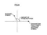
- the transmission path estimation part 52 obtains the amount of phase rotation based on the pilot signal, which is an output from the de-spreading part 26. As shown in Fig. 6, the amount of phase rotation is a phase difference between the received signal and received signal that are expected. The amount of phase rotation is determined by taking into account an effect of noise components on the pilot channel and by obtaining an average for M pieces of pilot symbols. The transmission path estimation part 52 transmits the amount of phase rotation to the data demodulation / decoding part 36.
- the information signals are turbo coded by the turbo coding part 12.
- the information signals, that have been turbo coded, are rate matched by the rate matching part 14.
- the information signals are converted into data block sizes suitable for communications.
- the information signals are modulated and spread, along with the pilot signals and the control signals, which indicate the modulation method, and are transmitted from the transmitter part 16 to the receiver apparatus 20.
- the rate matching ratio is also transmitted to the receiver apparatus 20 separately.
- the receiver part 22 of the receiver apparatus 20 receives the signals transmitted by the transmitter apparatus 10. These received signals are digitized by the A / D conversion part 24 and de-spread by the de-spreading part 26.
- the control signals which are an output from the de-spreading part 26, are demodulated and decoded by the control data demodulation / decoding part 42 and sent to the controller part 44.
- the controller part 44 reads out the demodulation format from the control signals.
- the pilot signals which are the output from the de-spreading part 26, are used by the transmission path estimation part 52 for obtaining the amount of phase rotation.
- the information signals which are the output from the de-spreading part 26, are rate de-matched by the rate de-matching part 32 and adjusted into block sizes that are suited for turbo decoding.
- the output signals from the rate de-matching part 32 are provided as the input signals I (i) to the normalizing apparatus 34.
- the weighting part 345 weights the normalized data I (i) / A by multiplying with the weighting coefficient ⁇ and provides an output. By the way, the weighting coefficient ⁇ is determined by the weighting coefficient determination part 344 based on the rate-matching ratio.
- a circuit size for realizing this normalizing apparatus 34 is small, because a receiving quality does not need to be measured.
- the data demodulation / decoding part 36 demodulates and turbo-decodes the output from the normalizing apparatus 34 with a demodulation format read out by the controller part 44. At this time, the amount of phase rotation obtained by the transmission path estimation part 52 is used for a phase correction.
- the level for the entire single frame tends to be small, when the rate-matching ratio is small.
- the smaller the rate-matching ratio the larger will the weighting coefficient determination part 344 make the weighting coefficient ⁇ .
- the weighting part 345 multiplies the normalized data I (i) / A with the weighting coefficient ⁇ , the level for the entire single frame of the input signals is maintained at a fairly constant level.
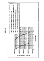
- Fig. 7 compares block error rates (in data block units for coding and decoding), when the LLR is used, and with the embodiment of the present invention.
- the quality levels resulting from using the LLR and from the embodiment of the present invention are approximately the same.
- the present invention is suited for application on a coding method, in which a power level of input signals into the decoder somehow affects decoding characteristics (error rates).
- a decoding method is, for example, the Log-MAP decoding.
- the Log-MAP decoding is a decoding method of selecting a larger value of two Branch Metric values and adding a correction term. It would not be necessary to perform the normalization process of the present invention for the Max-Log-MAP decoding, with which a larger value is simply selected out of the two Branch Metric values.
- the correction term in the Log-MAP decoding is stored in a reference table within a decoder.
- the signal power is not set appropriately, an inappropriate portion of the reference table would be read out, and the decoding characteristics can change significantly.
- a media accessing apparatus in a computer which includes a CPU, a hard disk, a flash memory, and a media accessing apparatus (for example, a floppy disk, a CD-ROM, or a memory stick), accesses a medium that stores a program, that implements the above-mentioned various parts, and installs on a hard disk or a flash memory.
- a media accessing apparatus for example, a floppy disk, a CD-ROM, or a memory stick
- the normalization is accomplished by dividing the turbo coded input signals by the average data. Furthermore, because the circuit size is relatively small, an increase in the circuit size is inhibited.
Landscapes
- Engineering & Computer Science (AREA)
- Computer Networks & Wireless Communication (AREA)
- Signal Processing (AREA)
- Physics & Mathematics (AREA)
- Probability & Statistics with Applications (AREA)
- Theoretical Computer Science (AREA)
- Error Detection And Correction (AREA)
Abstract
Description
| Rate Matching Ratios | Relationships Between Numbers of Input and Output Data in Rate Matching |
| Rate Matching Ratios > 1 | Number of Input Data < Number of Output Data |
| Rate Matching Ratios = 1 | Number of Input Data = Number of Output Data |
| Rate Matching Ratios < 1 | Number of Input Data > Number of Output Data |

Claims (12)
- A normalizing apparatus comprising:means of data averaging for outputting an average of turbo coded input signals as an average data; andmeans of division for outputting a value obtained by dividing said input signals by said average data as a normalized data.
- The normalizing apparatus of Claim 1, comprising means of weighting for multiplying said normalized data by a prescribed coefficient and providing an output.
- The normalizing apparatus of Claim 2, comprising means of weighting coefficient determination for determining said prescribed coefficient based on a ratio between the number of input data and the number of output data in a rate-matching of said input signals.
- A receiver comprising:the normalizing apparatus according to one of Claims 1 through Claim 3, andmeans of turbo decoding for turbo decoding an output from said normalizing apparatus.
- A method of normalization comprising:a step of data averaging for outputting an average of turbo coded input signals as an average data; anda step of division for outputting a value obtained by dividing said input signals by said average data as a normalized data.
- A program to be executed by a computer for performing:a process of data averaging for outputting an average of turbo coded input signals as an average data; anda process of division for outputting a value obtained by dividing said input signals by said average data as a normalized data.
- A recording medium that can be readable by a computer, which stores a program to be executed by the computer for performing:a process of data averaging for outputting an average of turbo coded input signals as an average data; anda process of division for outputting a value obtained by dividing said input signals by said average data as a normalized data.
- A communications terminal apparatus comprising:means of receiving for receiving coded signals separated into frame units;means of normalization for calculating an average value for signal levels for said coded signals, normalizing said coded signals and generating normalized signals;means of weighting coefficient determination for generating a weighting coefficient for said frame unit;means of weighting for multiplying said normalized signals and said weighting coefficient, and generating weighted signals; andmeans of decoding for decoding said weighted signals.
- The communications terminal apparatus of Claim 8, wherein said means of normalization calculates a signal level average value for the coded signals in said frame unit.
- The communications terminal apparatus of Claim 8, wherein
a rate-matching process is performed on said coded signals; and
said means of weighting coefficient determination determines said weighting coefficient based on a ratio between the number of input data and the number of output data in said rate-matching process. - The communications terminal apparatus of Claim 8 wherein
said coded signals are turbo coded signals; and
said means of decoding performs a turbo decoding process on said weighted signals. - The communications terminal apparatus of Claim 11 wherein said turbo decoding process comprises a Log-MAP decoding process.
Applications Claiming Priority (3)
| Application Number | Priority Date | Filing Date | Title |
|---|---|---|---|
| JP2001152886 | 2001-05-22 | ||
| JP2001152886A JP3624855B2 (en) | 2001-05-22 | 2001-05-22 | Normalization device, method, program, recording medium recording the program, and communication terminal device |
| PCT/JP2002/004959 WO2002095954A1 (en) | 2001-05-22 | 2002-05-22 | Normalizing device and method, program, record medium on which the program is recorded, and communication terminal |
Publications (3)
| Publication Number | Publication Date |
|---|---|
| EP1394952A1 true EP1394952A1 (en) | 2004-03-03 |
| EP1394952A4 EP1394952A4 (en) | 2006-03-22 |
| EP1394952B1 EP1394952B1 (en) | 2007-11-07 |
Family
ID=18997495
Family Applications (1)
| Application Number | Title | Priority Date | Filing Date |
|---|---|---|---|
| EP02728112A Expired - Lifetime EP1394952B1 (en) | 2001-05-22 | 2002-05-22 | Normalisation for turbo decoding |
Country Status (6)
| Country | Link |
|---|---|
| US (1) | US7131053B2 (en) |
| EP (1) | EP1394952B1 (en) |
| JP (1) | JP3624855B2 (en) |
| KR (1) | KR20040007588A (en) |
| DE (1) | DE60223362D1 (en) |
| WO (1) | WO2002095954A1 (en) |
Families Citing this family (5)
| Publication number | Priority date | Publication date | Assignee | Title |
|---|---|---|---|---|
| BRPI0805829B1 (en) | 2007-05-14 | 2020-05-26 | Samsung Electronics Co., Ltd | METHOD OF TRANSMITTING A MOBILE DIFFUSION SERVICE, AND APPLIANCE FOR TRANSMITTING A MOBILE DIFFUSION SERVICE |
| US7983251B2 (en) | 2007-05-17 | 2011-07-19 | Samsung Electronics Co., Ltd. | Broadcasting service transmission/reception method and apparatus for providing fast access to broadcasting service |
| WO2008156257A2 (en) | 2007-06-18 | 2008-12-24 | Samsung Electronics Co., Ltd. | Method and apparatus for transporting mobile broadcasting service, and method and apparatus for receiving mobile broadcasting service |
| US8995353B2 (en) | 2007-10-09 | 2015-03-31 | Samsung Electronics Co., Ltd. | Method and apparatus for transmitting broadcast data and method and apparatus for receiving broadcast data |
| EP3514791B1 (en) * | 2016-09-15 | 2021-07-28 | Nippon Telegraph and Telephone Corporation | Sample sequence converter, sample sequence converting method and program |
Family Cites Families (10)
| Publication number | Priority date | Publication date | Assignee | Title |
|---|---|---|---|---|
| US6965630B1 (en) * | 2000-10-10 | 2005-11-15 | Freescale Semiconductor, Inc. | Mode Controller for signal acquisition and tracking in an ultra wideband communication system |
| JP3144411B2 (en) * | 1999-03-17 | 2001-03-12 | 株式会社ワイ・アール・ピー移動通信基盤技術研究所 | Spread spectrum communication equipment |
| US6377607B1 (en) * | 1999-05-13 | 2002-04-23 | Qualcomm Incorporated | System and method for performing accurate demodulation of turbo-encoded signals via pilot assisted coherent demodulation |
| JP3928311B2 (en) * | 1999-09-06 | 2007-06-13 | 三菱電機株式会社 | Turbo code error correction decoding apparatus and turbo code error correction decoding method |
| EP1187344B1 (en) * | 2000-08-28 | 2005-11-23 | Sony Deutschland Gmbh | Soft-normaliser for a channel decoder |
| JP2002076920A (en) * | 2000-08-30 | 2002-03-15 | Toshiba Corp | Error correction device |
| JP3497480B2 (en) * | 2000-09-04 | 2004-02-16 | 松下電器産業株式会社 | Phase rotation detection device and radio base station device provided with the same |
| US7430237B2 (en) * | 2001-02-20 | 2008-09-30 | Lucent Technologies Inc. | Decoderless bit-error-rate estimation for convolutionally encoded transmissions in wireless systems |
| KR100449578B1 (en) * | 2001-09-14 | 2004-09-21 | 한국전자통신연구원 | Iterative decoding method for block turbo codes more than 3-dimensions |
| CA2405322A1 (en) * | 2001-09-28 | 2003-03-28 | Telecommunications Research Laboratories | Channel code decoding for the cdma forward link |
-
2001
- 2001-05-22 JP JP2001152886A patent/JP3624855B2/en not_active Expired - Fee Related
-
2002
- 2002-05-22 WO PCT/JP2002/004959 patent/WO2002095954A1/en not_active Ceased
- 2002-05-22 KR KR10-2003-7015184A patent/KR20040007588A/en not_active Abandoned
- 2002-05-22 US US10/478,766 patent/US7131053B2/en not_active Expired - Fee Related
- 2002-05-22 DE DE60223362T patent/DE60223362D1/en not_active Expired - Lifetime
- 2002-05-22 EP EP02728112A patent/EP1394952B1/en not_active Expired - Lifetime
Also Published As
| Publication number | Publication date |
|---|---|
| US7131053B2 (en) | 2006-10-31 |
| EP1394952A4 (en) | 2006-03-22 |
| JP2002353820A (en) | 2002-12-06 |
| WO2002095954A1 (en) | 2002-11-28 |
| EP1394952B1 (en) | 2007-11-07 |
| JP3624855B2 (en) | 2005-03-02 |
| DE60223362D1 (en) | 2007-12-20 |
| US20040158792A1 (en) | 2004-08-12 |
| KR20040007588A (en) | 2004-01-24 |
Similar Documents
| Publication | Publication Date | Title |
|---|---|---|
| US6662337B1 (en) | Digital transmission system and method | |
| EP1190489B1 (en) | Optimum turbo decoding architecture and method using a constant or quasi-constant signal-to-noise ratio | |
| US7340013B2 (en) | Soft sample scaling in a turbo decoder | |
| US6629286B1 (en) | Method and device for assessing the quality of service on transmission channels in a digital transmission system | |
| ES2282323T3 (en) | METHOD FOR ESTIMATING ERROR RATES IN RECEPTORS USING ITERATIVE DECODING. | |
| EP1264456A2 (en) | Method and apparatus for combined soft-decision based interference cancellation and decoding | |
| US8406354B2 (en) | Interference cancellation in a multi-user receiver | |
| US6536010B1 (en) | Digital transmission system and method | |
| CA2354463C (en) | Quantization method for iterative decoder in communication system | |
| EP1394952A1 (en) | NORMALIZING DEVICE AND METHOD&comma; PROGRAM&comma; RECORD MEDIUM ON WHICH THE PROGRAM IS RECORDED&comma; AND COMMUNICATION TERMINAL | |
| EP1235379A1 (en) | Decoderless bit-error-rate estimation for convolutionally encoded transmissions in wireless systems | |
| US8687746B2 (en) | SMU architecture for turbo decoder | |
| KR100724986B1 (en) | Method and apparatus for determining scaling factor for input data of turbo decoder in code division multiple access system | |
| JP2003258775A (en) | Iteration decoding system and power consumption reduction method therein | |
| JP2005260608A (en) | Receiving unit, portable communication terminal and decoding method |
Legal Events
| Date | Code | Title | Description |
|---|---|---|---|
| PUAI | Public reference made under article 153(3) epc to a published international application that has entered the european phase |
Free format text: ORIGINAL CODE: 0009012 |
|
| 17P | Request for examination filed |
Effective date: 20031106 |
|
| AK | Designated contracting states |
Kind code of ref document: A1 Designated state(s): AT BE CH CY DE DK ES FI FR GB GR IE IT LI LU MC NL PT SE TR |
|
| A4 | Supplementary search report drawn up and despatched |
Effective date: 20060203 |
|
| 17Q | First examination report despatched |
Effective date: 20060630 |
|
| GRAP | Despatch of communication of intention to grant a patent |
Free format text: ORIGINAL CODE: EPIDOSNIGR1 |
|
| RTI1 | Title (correction) |
Free format text: NORMALISATION FOR TURBO DECODING |
|
| RBV | Designated contracting states (corrected) |
Designated state(s): DE FR GB |
|
| GRAS | Grant fee paid |
Free format text: ORIGINAL CODE: EPIDOSNIGR3 |
|
| GRAA | (expected) grant |
Free format text: ORIGINAL CODE: 0009210 |
|
| AK | Designated contracting states |
Kind code of ref document: B1 Designated state(s): DE FR GB |
|
| REG | Reference to a national code |
Ref country code: GB Ref legal event code: FG4D |
|
| REF | Corresponds to: |
Ref document number: 60223362 Country of ref document: DE Date of ref document: 20071220 Kind code of ref document: P |
|
| EN | Fr: translation not filed | ||
| PLBE | No opposition filed within time limit |
Free format text: ORIGINAL CODE: 0009261 |
|
| STAA | Information on the status of an ep patent application or granted ep patent |
Free format text: STATUS: NO OPPOSITION FILED WITHIN TIME LIMIT |
|
| 26N | No opposition filed |
Effective date: 20080808 |
|
| PG25 | Lapsed in a contracting state [announced via postgrant information from national office to epo] |
Ref country code: FR Free format text: LAPSE BECAUSE OF FAILURE TO SUBMIT A TRANSLATION OF THE DESCRIPTION OR TO PAY THE FEE WITHIN THE PRESCRIBED TIME-LIMIT Effective date: 20080822 Ref country code: DE Free format text: LAPSE BECAUSE OF FAILURE TO SUBMIT A TRANSLATION OF THE DESCRIPTION OR TO PAY THE FEE WITHIN THE PRESCRIBED TIME-LIMIT Effective date: 20080208 |
|
| GBPC | Gb: european patent ceased through non-payment of renewal fee |
Effective date: 20080522 |
|
| PG25 | Lapsed in a contracting state [announced via postgrant information from national office to epo] |
Ref country code: GB Free format text: LAPSE BECAUSE OF NON-PAYMENT OF DUE FEES Effective date: 20080522 |