EP1394883A1 - Solid-oxide fuel cell system having tempering of fuel cell stacks by exhaust gas - Google Patents
Solid-oxide fuel cell system having tempering of fuel cell stacks by exhaust gas Download PDFInfo
- Publication number
- EP1394883A1 EP1394883A1 EP03076576A EP03076576A EP1394883A1 EP 1394883 A1 EP1394883 A1 EP 1394883A1 EP 03076576 A EP03076576 A EP 03076576A EP 03076576 A EP03076576 A EP 03076576A EP 1394883 A1 EP1394883 A1 EP 1394883A1
- Authority
- EP
- European Patent Office
- Prior art keywords
- fuel cell
- fuel
- air
- exhaust
- stack
- Prior art date
- Legal status (The legal status is an assumption and is not a legal conclusion. Google has not performed a legal analysis and makes no representation as to the accuracy of the status listed.)
- Granted
Links
Images


Classifications
-
- H—ELECTRICITY
- H01—ELECTRIC ELEMENTS
- H01M—PROCESSES OR MEANS, e.g. BATTERIES, FOR THE DIRECT CONVERSION OF CHEMICAL ENERGY INTO ELECTRICAL ENERGY
- H01M8/00—Fuel cells; Manufacture thereof
- H01M8/04—Auxiliary arrangements, e.g. for control of pressure or for circulation of fluids
- H01M8/04007—Auxiliary arrangements, e.g. for control of pressure or for circulation of fluids related to heat exchange
- H01M8/04014—Heat exchange using gaseous fluids; Heat exchange by combustion of reactants
- H01M8/04022—Heating by combustion
-
- H—ELECTRICITY
- H01—ELECTRIC ELEMENTS
- H01M—PROCESSES OR MEANS, e.g. BATTERIES, FOR THE DIRECT CONVERSION OF CHEMICAL ENERGY INTO ELECTRICAL ENERGY
- H01M8/00—Fuel cells; Manufacture thereof
- H01M8/04—Auxiliary arrangements, e.g. for control of pressure or for circulation of fluids
- H01M8/04007—Auxiliary arrangements, e.g. for control of pressure or for circulation of fluids related to heat exchange
- H01M8/04014—Heat exchange using gaseous fluids; Heat exchange by combustion of reactants
-
- H—ELECTRICITY
- H01—ELECTRIC ELEMENTS
- H01M—PROCESSES OR MEANS, e.g. BATTERIES, FOR THE DIRECT CONVERSION OF CHEMICAL ENERGY INTO ELECTRICAL ENERGY
- H01M8/00—Fuel cells; Manufacture thereof
- H01M8/04—Auxiliary arrangements, e.g. for control of pressure or for circulation of fluids
- H01M8/04223—Auxiliary arrangements, e.g. for control of pressure or for circulation of fluids during start-up or shut-down; Depolarisation or activation, e.g. purging; Means for short-circuiting defective fuel cells
- H01M8/04268—Heating of fuel cells during the start-up of the fuel cells
-
- H—ELECTRICITY
- H01—ELECTRIC ELEMENTS
- H01M—PROCESSES OR MEANS, e.g. BATTERIES, FOR THE DIRECT CONVERSION OF CHEMICAL ENERGY INTO ELECTRICAL ENERGY
- H01M8/00—Fuel cells; Manufacture thereof
- H01M8/06—Combination of fuel cells with means for production of reactants or for treatment of residues
- H01M8/0662—Treatment of gaseous reactants or gaseous residues, e.g. cleaning
-
- H—ELECTRICITY
- H01—ELECTRIC ELEMENTS
- H01M—PROCESSES OR MEANS, e.g. BATTERIES, FOR THE DIRECT CONVERSION OF CHEMICAL ENERGY INTO ELECTRICAL ENERGY
- H01M8/00—Fuel cells; Manufacture thereof
- H01M8/10—Fuel cells with solid electrolytes
- H01M8/12—Fuel cells with solid electrolytes operating at high temperature, e.g. with stabilised ZrO2 electrolyte
- H01M8/124—Fuel cells with solid electrolytes operating at high temperature, e.g. with stabilised ZrO2 electrolyte characterised by the process of manufacturing or by the material of the electrolyte
- H01M8/1246—Fuel cells with solid electrolytes operating at high temperature, e.g. with stabilised ZrO2 electrolyte characterised by the process of manufacturing or by the material of the electrolyte the electrolyte consisting of oxides
-
- H—ELECTRICITY
- H01—ELECTRIC ELEMENTS
- H01M—PROCESSES OR MEANS, e.g. BATTERIES, FOR THE DIRECT CONVERSION OF CHEMICAL ENERGY INTO ELECTRICAL ENERGY
- H01M8/00—Fuel cells; Manufacture thereof
- H01M8/24—Grouping of fuel cells, e.g. stacking of fuel cells
- H01M8/241—Grouping of fuel cells, e.g. stacking of fuel cells with solid or matrix-supported electrolytes
- H01M8/2425—High-temperature cells with solid electrolytes
- H01M8/2428—Grouping by arranging unit cells on a surface of any form, e.g. planar or tubular
-
- H—ELECTRICITY
- H01—ELECTRIC ELEMENTS
- H01M—PROCESSES OR MEANS, e.g. BATTERIES, FOR THE DIRECT CONVERSION OF CHEMICAL ENERGY INTO ELECTRICAL ENERGY
- H01M8/00—Fuel cells; Manufacture thereof
- H01M8/24—Grouping of fuel cells, e.g. stacking of fuel cells
- H01M8/241—Grouping of fuel cells, e.g. stacking of fuel cells with solid or matrix-supported electrolytes
- H01M8/2425—High-temperature cells with solid electrolytes
- H01M8/2432—Grouping of unit cells of planar configuration
-
- H—ELECTRICITY
- H01—ELECTRIC ELEMENTS
- H01M—PROCESSES OR MEANS, e.g. BATTERIES, FOR THE DIRECT CONVERSION OF CHEMICAL ENERGY INTO ELECTRICAL ENERGY
- H01M8/00—Fuel cells; Manufacture thereof
- H01M8/24—Grouping of fuel cells, e.g. stacking of fuel cells
- H01M8/2457—Grouping of fuel cells, e.g. stacking of fuel cells with both reactants being gaseous or vaporised
-
- H—ELECTRICITY
- H01—ELECTRIC ELEMENTS
- H01M—PROCESSES OR MEANS, e.g. BATTERIES, FOR THE DIRECT CONVERSION OF CHEMICAL ENERGY INTO ELECTRICAL ENERGY
- H01M8/00—Fuel cells; Manufacture thereof
- H01M8/24—Grouping of fuel cells, e.g. stacking of fuel cells
- H01M8/2465—Details of groupings of fuel cells
- H01M8/2483—Details of groupings of fuel cells characterised by internal manifolds
-
- H—ELECTRICITY
- H01—ELECTRIC ELEMENTS
- H01M—PROCESSES OR MEANS, e.g. BATTERIES, FOR THE DIRECT CONVERSION OF CHEMICAL ENERGY INTO ELECTRICAL ENERGY
- H01M8/00—Fuel cells; Manufacture thereof
- H01M8/24—Grouping of fuel cells, e.g. stacking of fuel cells
- H01M8/2465—Details of groupings of fuel cells
- H01M8/2484—Details of groupings of fuel cells characterised by external manifolds
- H01M8/2485—Arrangements for sealing external manifolds; Arrangements for mounting external manifolds around a stack
-
- F—MECHANICAL ENGINEERING; LIGHTING; HEATING; WEAPONS; BLASTING
- F28—HEAT EXCHANGE IN GENERAL
- F28D—HEAT-EXCHANGE APPARATUS, NOT PROVIDED FOR IN ANOTHER SUBCLASS, IN WHICH THE HEAT-EXCHANGE MEDIA DO NOT COME INTO DIRECT CONTACT
- F28D9/00—Heat-exchange apparatus having stationary plate-like or laminated conduit assemblies for both heat-exchange media, the media being in contact with different sides of a conduit wall
- F28D9/0031—Heat-exchange apparatus having stationary plate-like or laminated conduit assemblies for both heat-exchange media, the media being in contact with different sides of a conduit wall the conduits for one heat-exchange medium being formed by paired plates touching each other
- F28D9/0043—Heat-exchange apparatus having stationary plate-like or laminated conduit assemblies for both heat-exchange media, the media being in contact with different sides of a conduit wall the conduits for one heat-exchange medium being formed by paired plates touching each other the plates having openings therein for circulation of at least one heat-exchange medium from one conduit to another
- F28D9/005—Heat-exchange apparatus having stationary plate-like or laminated conduit assemblies for both heat-exchange media, the media being in contact with different sides of a conduit wall the conduits for one heat-exchange medium being formed by paired plates touching each other the plates having openings therein for circulation of at least one heat-exchange medium from one conduit to another the plates having openings therein for both heat-exchange media
-
- H—ELECTRICITY
- H01—ELECTRIC ELEMENTS
- H01M—PROCESSES OR MEANS, e.g. BATTERIES, FOR THE DIRECT CONVERSION OF CHEMICAL ENERGY INTO ELECTRICAL ENERGY
- H01M2250/00—Fuel cells for particular applications; Specific features of fuel cell system
- H01M2250/20—Fuel cells in motive systems, e.g. vehicle, ship, plane
-
- H—ELECTRICITY
- H01—ELECTRIC ELEMENTS
- H01M—PROCESSES OR MEANS, e.g. BATTERIES, FOR THE DIRECT CONVERSION OF CHEMICAL ENERGY INTO ELECTRICAL ENERGY
- H01M8/00—Fuel cells; Manufacture thereof
- H01M8/04—Auxiliary arrangements, e.g. for control of pressure or for circulation of fluids
- H01M8/04082—Arrangements for control of reactant parameters, e.g. pressure or concentration
- H01M8/04201—Reactant storage and supply, e.g. means for feeding, pipes
-
- H—ELECTRICITY
- H01—ELECTRIC ELEMENTS
- H01M—PROCESSES OR MEANS, e.g. BATTERIES, FOR THE DIRECT CONVERSION OF CHEMICAL ENERGY INTO ELECTRICAL ENERGY
- H01M8/00—Fuel cells; Manufacture thereof
- H01M8/24—Grouping of fuel cells, e.g. stacking of fuel cells
- H01M8/241—Grouping of fuel cells, e.g. stacking of fuel cells with solid or matrix-supported electrolytes
- H01M8/2425—High-temperature cells with solid electrolytes
-
- H—ELECTRICITY
- H01—ELECTRIC ELEMENTS
- H01M—PROCESSES OR MEANS, e.g. BATTERIES, FOR THE DIRECT CONVERSION OF CHEMICAL ENERGY INTO ELECTRICAL ENERGY
- H01M8/00—Fuel cells; Manufacture thereof
- H01M8/24—Grouping of fuel cells, e.g. stacking of fuel cells
- H01M8/2465—Details of groupings of fuel cells
- H01M8/247—Arrangements for tightening a stack, for accommodation of a stack in a tank or for assembling different tanks
- H01M8/2475—Enclosures, casings or containers of fuel cell stacks
-
- H—ELECTRICITY
- H01—ELECTRIC ELEMENTS
- H01M—PROCESSES OR MEANS, e.g. BATTERIES, FOR THE DIRECT CONVERSION OF CHEMICAL ENERGY INTO ELECTRICAL ENERGY
- H01M8/00—Fuel cells; Manufacture thereof
- H01M8/24—Grouping of fuel cells, e.g. stacking of fuel cells
- H01M8/249—Grouping of fuel cells, e.g. stacking of fuel cells comprising two or more groupings of fuel cells, e.g. modular assemblies
-
- Y—GENERAL TAGGING OF NEW TECHNOLOGICAL DEVELOPMENTS; GENERAL TAGGING OF CROSS-SECTIONAL TECHNOLOGIES SPANNING OVER SEVERAL SECTIONS OF THE IPC; TECHNICAL SUBJECTS COVERED BY FORMER USPC CROSS-REFERENCE ART COLLECTIONS [XRACs] AND DIGESTS
- Y02—TECHNOLOGIES OR APPLICATIONS FOR MITIGATION OR ADAPTATION AGAINST CLIMATE CHANGE
- Y02E—REDUCTION OF GREENHOUSE GAS [GHG] EMISSIONS, RELATED TO ENERGY GENERATION, TRANSMISSION OR DISTRIBUTION
- Y02E60/00—Enabling technologies; Technologies with a potential or indirect contribution to GHG emissions mitigation
- Y02E60/30—Hydrogen technology
- Y02E60/50—Fuel cells
-
- Y—GENERAL TAGGING OF NEW TECHNOLOGICAL DEVELOPMENTS; GENERAL TAGGING OF CROSS-SECTIONAL TECHNOLOGIES SPANNING OVER SEVERAL SECTIONS OF THE IPC; TECHNICAL SUBJECTS COVERED BY FORMER USPC CROSS-REFERENCE ART COLLECTIONS [XRACs] AND DIGESTS
- Y02—TECHNOLOGIES OR APPLICATIONS FOR MITIGATION OR ADAPTATION AGAINST CLIMATE CHANGE
- Y02P—CLIMATE CHANGE MITIGATION TECHNOLOGIES IN THE PRODUCTION OR PROCESSING OF GOODS
- Y02P70/00—Climate change mitigation technologies in the production process for final industrial or consumer products
- Y02P70/50—Manufacturing or production processes characterised by the final manufactured product
-
- Y—GENERAL TAGGING OF NEW TECHNOLOGICAL DEVELOPMENTS; GENERAL TAGGING OF CROSS-SECTIONAL TECHNOLOGIES SPANNING OVER SEVERAL SECTIONS OF THE IPC; TECHNICAL SUBJECTS COVERED BY FORMER USPC CROSS-REFERENCE ART COLLECTIONS [XRACs] AND DIGESTS
- Y02—TECHNOLOGIES OR APPLICATIONS FOR MITIGATION OR ADAPTATION AGAINST CLIMATE CHANGE
- Y02T—CLIMATE CHANGE MITIGATION TECHNOLOGIES RELATED TO TRANSPORTATION
- Y02T90/00—Enabling technologies or technologies with a potential or indirect contribution to GHG emissions mitigation
- Y02T90/40—Application of hydrogen technology to transportation, e.g. using fuel cells
Definitions
- the present invention relates to hydrogen/oxygen fuel cells having a solid-oxide electrolytic layer separating an anode layer from a cathode layer; more particularly, to fuel cell assemblies comprising a plurality of individual fuel cells in a stack wherein air and reformed fuel are supplied to the stack; and most particularly, to a fuel cell system including an on-board hydrocarbon reformer, waste energy recovery assembly including a spent fuel combustor and cathode air heat exchangers, an air supply assembly, a control system, and a three-dimensional fuel/air manifold, wherein exhaust gas from the combustor, after passing through the cathode air heat exchangers is passed around the fuel cell stack to temper the stack.
- Fuel cells which generate electric current by the electrochemical combination of hydrogen and oxygen are well known.
- an anodic layer and a cathodic layer are separated by an electrolyte formed of a ceramic solid oxide.
- Such a fuel cell is known in the art as a "solid oxide fuel cell” (SOFC).
- Hydrogen either pure or reformed from hydrocarbons, is flowed along the outer surface of the anode and diffuses into the anode.
- Oxygen typically from air, is flowed along the outer surface of the cathode and diffuses into the cathode.
- Each O 2 molecule is split and reduced to two O -2 anions catalytically by the cathode.
- the oxygen anions diffuse through the electrolyte and combine at the anode/electrolyte interface with four hydrogen ions to form two molecules of water.
- the anode and the cathode are connected externally through a load to complete the circuit whereby four electrons are transferred from the anode to the cathode.
- hydrogen is derived by "reforming" hydrocarbons such as gasoline in the presence of limited oxygen
- the "reformate” gas includes CO which is converted to CO 2 at the anode via an oxidation process similar to that of the hydrogen.
- Reformed gasoline is a commonly used fuel in automotive fuel cell applications.
- a single cell is capable of generating a relatively small voltage and wattage, typically between about 0.5 volt and about 1.0 volt, depending upon load, and less than about 2 watts per cm 2 of cell surface. Therefore, in practice it is known to stack together, in electrical series, a plurality of cells. Because each anode and cathode must have a free space for passage of gas over its surface, the cells are separated by perimeter spacers which are selectively vented to permit flow of gas to the anodes and cathodes as desired but which form seals on their axial surfaces to prevent gas leakage from the sides of the stack.
- the perimeter spacers may include dielectric layers to insulate the interconnects from each other.
- Adjacent cells are connected electrically by "interconnect" elements in the stack, the outer surfaces of the anodes and cathodes being electrically connected to their respective interconnects by electrical contacts disposed within the gas-flow space, typically by a metallic foam which is readily gas-permeable or by conductive filaments.
- the outermost, or end, interconnects of the stack define electric terminals, or "current collectors,” which may be connected across a load.
- a complete SOFC system typically includes auxiliary subsystems for, among other requirements, generating fuel by reforming hydrocarbons; tempering the reformate fuel and air entering the stack; providing air to the hydrocarbon reformer; providing air to the cathodes for reaction with hydrogen in the fuel cell stack; providing air for cooling the fuel cell stack; providing combustion air to a combustor for tail gas fuel exiting the stack; and providing air to the combustor and the stack.
- the fuel cell stack produces waste heat which must be removed to maintain the correct stack temperature. This is typically accomplished by flowing excess cathode air which then provides a cooling function from within the stack.
- this excess cathode air which may be three to four times the amount required to oxidize the fuel, requires additional power in the air supply system, which power is a parasitic loss and thus reduces the overall efficiency of the system.
- a fuel/air manifold conveys air and tail gas fuel from the anodes to a tail gas combustor, producing a heated combustor exhaust having the highest mass flow in the system.
- the exhaust is passed through a heat exchanger to warm incoming cathode reaction air, and the exhaust is partially cooled in the exchange.
- the exhaust gas is passed through a tempering jacket surrounding the fuel cells in a stack.
- the exhaust gas is hotter than the stack and so the warm-up period is shortened.
- the exhaust gas is cooler than the operating temperature and therefore cooling of the stack is assisted by contact with the exhaust gas.
- a fuel cell stack 10 includes elements known in the art of solid-oxide fuel cell stacks comprising more than one fuel cell.
- the example shown includes two identical fuel cells 11, connected in series, and is of a class of such fuel cells said to be "anode-supported" in that the anode is a structural element having the electrolyte and cathode deposited upon it. Element thicknesses as shown are not to scale.
- Each fuel cell 11 includes an electrolyte element 14 separating an anodic element 16 and a cathodic element 18.
- Each anode and cathode is in direct chemical contact with its respective surface of the electrolyte, and each anode and cathode has a respective free surface 20,22 forming one wall of a respective passageway 24,26 for flow of gas across the surface.
- Anode 16 of one fuel cell 11 faces and is electrically connected to an interconnect 28 by filaments 30 extending across but not blocking passageway 24.
- cathode 18 of fuel cell 11 faces and is electrically connected to interconnect 28 by filaments 30 extending across but not blocking passageway 26.
- cathode 18 of a second fuel cell 11 faces and is electrically connected to a cathodic current collector 32 by filaments 30 extending across but not blocking passageway 26
- anode 16 of fuel cell 11 faces and is electrically connected to an anodic current collector 34 by filaments 30 extending across but not blocking passageway 24.
- Current collectors 32,34 may be connected across a load 35 in order that the fuel cell stack 10 performs electrical work.
- Passageways 24 are formed by anode spacers 36 between the perimeter of anode 16 and either interconnect 28 or anodic current collector 34.
- Passageways 26 are formed by cathode spacers 38 between the perimeter of electrolyte 14 and either interconnect 28 or cathodic current collector 32.
- Anode spacer 36 and cathode spacer 38 are formed from sheet stock in such a way as to yield the desired height of the anode passageways 24 and cathode passageways 26.
- the interconnect and the current collectors are formed of an alloy, typically a "superalloy,” which is chemically and dimensionally stable at the elevated temperatures necessary for fuel cell operation, generally about 750°C or higher, for example, Hastelloy, Haynes 230, or a stainless steel.
- the electrolyte is formed of a ceramic oxide and preferably includes zirconia stabilized with yttrium oxide (yttria), known in the art as YSZ.
- the cathode is formed of, for example, porous lanthanum strontium manganate or lanthanum strontium iron, and the anode is formed of, for example, a mixture of nickel and YSZ.
- reformate gas 21 is provided to passageways 24 at a first edge 25 of the anode free surface 20, flows parallel to the surface of the anode across the anode in a first direction, and is removed at a second and opposite edge 29 of anode surface 20.
- Hydrogen and CO diffuse into the anode to the interface with the electrolyte.
- Oxygen 31, typically in air, is provided to passageways 26 at a first edge 39 of the cathode free surface 22, flows parallel to the surface of the cathode in a second direction which can be orthogonal to the first direction of the reformate (second direction shown in the same direction as the first for clarity in FIG. 1), and is removed at a second and opposite edge 43 of cathode surface 22.
- O 2 Molecular oxygen gas diffuses into the cathode and is catalytically reduced to two O -2 anions by accepting four electrons from the cathode and the cathodic current collector 32 or the interconnect 28 via filaments 30.
- the electrolyte ionically conducts or transports O -2 anions to the anode electrolyte innerface where they combine with four hydrogen atoms to form two water molecules, giving up four electrons to the anode and the anodic current collector 34 or the interconnect 28 via filaments 30.
- cells 11 are connected in series electrically between the two current collectors, and the total voltage and wattage between the current collectors is the sum of the voltage and wattage of the individual cells in a fuel cell stack.
- a schematic mechanization diagram of a solid-oxide fuel cell system 12 in accordance with the invention includes auxiliary equipment and controls.
- a conventional high speed inlet air pump 48 draws inlet air 50 through an air filter 52, past a first MAF sensor 54, through a sonic silencer 56, and through a cooling shroud 58 surrounding pump 48.
- Feed 62 goes as burner cooling air 64 to a tail gas afterburner 66 having an igniter 67 via a second MAF sensor 68 and a burner cool air control valve 70.
- Feed 72 is further split into branched conduits between an anode air feed 74 and a cathode air feed 75.
- Anode feed 74 goes to a hydrocarbon fuel vaporizer 76 via a third MAF sensor 78 and reformer air control valve 80.
- a portion of anode air feed 74 may be controllably diverted by control valve 82 through the cool side 83 of reformate pre-heat heat exchanger 84, then recombined with the non-tempered portion such that feed 74 is tempered to a desired temperature on its way to vaporizer 76.
- Downstream of vaporizer 76 is a start-up combustor 77 having an igniter 79.
- Cathode air feed 75 is controlled by cathode air control valve 86 and may be controllably diverted by cathode air preheat bypass valve 88 through the cool side 90 of cathode air pre-heat heat exchanger 92 on its way to stacks 44,46. After passing through the cathode sides of the cells in stacks 44,46, the partially spent, heated air 93 is fed to burner 66.
- a hydrocarbon fuel feed pump 94 draws fuel from a storage tank 96 and delivers the fuel via a pressure regulator 98 and filter 100 to a fuel injector 102 which injects the fuel into vaporizer 76.
- the injected fuel is combined with air feed 74, vaporized, and fed to a reformer catalyst 104 in main fuel reformer 106 which reforms the fuel to, principally, hydrogen and carbon monoxide. Reformate 108 from catalyst 104 is fed to the anodes in stacks 44,46.
- Unconsumed fuel 110 from the anodes is fed to afterburner 66 where it is combined with air supplies 64 and 93 and is burned. When gases are below self ignition temperature, they are ignited by igniter 67.
- the hot burner gases 112 are passed through a cleanup catalyst 114 in main reformer 106.
- the effluent 115 from catalyst 114 is passed through the hot sides 116,118 of heat exchangers 84, 92, respectively, to heat the incoming cathode and anode air.
- the partially-cooled effluent 115 is fed to a manifold 120 surrounding stacks 44,46 from whence it is eventually exhausted 122.
- a first check valve 150 and a first oxygen getter device 124 are provided in the conduit feeding reformate 108 to the anodes (not visible) in stacks 44,46.
- a second check valve 152 and second oxygen getter device 126 are similarly provided in the conduit feeding spent reformate 110 from the anodes to afterburner 66.
- Each check valve includes a typical frusto-conical valve seat 154 receptive of a valve ball 156.
- each valve 150,152 is oriented within assembly 12 such that the ball is held in the seat by gravity when reformate is flowed through the system in the forward direction.
- fuel flow opens the valve sufficiently for fuel to pass in the forward direction.
- each valve is closed by gravity.
- the valves may not be identical, as oxygen flows opposite to the reformate in valve 152, but in the same direction as the reformate in valve 150; the so the balls and seats may require different weights and/or sizes to function as intended.
- Each getter 124,126 includes a passageway 128 having an inlet 130 and an outlet 132 through which reformate is passed during operation of the fuel cell assembly.
- a readily-oxidized material 134 oxygen-reducing means
- nickel metal foam, nickel wire or nickel mesh which is capable of gettering oxygen by reaction therewith but which does not present a significant obstruction to flow of reformate through the passageway.
- Nickel in the getters reacts with oxygen to produce nickel oxide, NiO, when the assembly is shut down, thus protecting the nickel-containing anodes from oxidation.
- reformate is again produced which, in passing through the getters, reduces the NiO back to metallic nickel, allowing the getters to be used repeatedly.
- the cells 311 are arranged side-by-side and may comprise a plurality of cells 311, respectively, such that each of first stack 344 and second stack 346 is a stack of identical fuel cells 311.
- the plurality of cells is preferably about 30 in each of the two stacks.
- the cells 311 in stack 344 and stack 346 are connected electrically in series by interconnect 347, and the stacks are connected in series with cathode current collector 332 and anode current collector 334 on the bottom of the stacks.
- the current collectors are sized to have a "footprint" very close to the same dimension as a cover-sealing flange 340.
- the current collectors preferably are adhesively sealed to a stack mounting plate 338, and the stacks preferably are in turn adhesively sealed to the current collectors.
- the sealing flange 340 for the cover 342 and top 343 is then mounted and sealed to the current collector plates.
- a gasket 341 between flange 340 and the current collectors is a dielectric so that flange 340 does not cause a short between the current collectors.
- Power leads 350,352 are attached to current collectors 332,334, respectively, through strong, reliable and highly conductive metallurgical bonds, such as brazing.
- the current collectors may pass under the cover mounting flange 340, with no additional sealing or power lead attachment required, and do not have to pass undesirably through the cover itself, as in some prior art stack assemblies. Passing leads through the cover makes the assembly more complex and less reliable.
- a fuel cell assembly 400 in accordance with the invention comprises stack assembly 300 operatively mounted on an integrated fuel/air manifold assembly 500 which also supports first and second cathode air heat exchangers 600 and an integrated fuel reformer and waste energy recovery unit (“reforWER”) 1100.
- Assembly 400 receives air from air supply system 900 (FIGS. 10-12) as described below and selectively preheats air going to the reformer.
- ReforWER 1100 reforms hydrocarbon fuel, such as gasoline, into reformate fuel gas comprising mostly hydrogen, carbon monoxide, and lower-molecular weight hydrocarbons, tempers the air and reformate entering the stacks, selectively burns fuel not consumed in the stacks, recovers heat energy generated in various internal processes which would otherwise be wasted, and exhausts spent air and water, all in order to efficiently generate DC electric potential across power leads 350,352 (not visible in FIG. 8).
- FIGS. 9 and 11 there are two basic functions for the enclosure of a fuel cell system.
- the first is to provide thermal insulation for the components which function at an elevated temperature (700-900°C) to maintain them at that temperature for efficient operation, to protect lower temperature components, and to reduce the exterior temperature over the overall unit to a human-safe level.
- the second is to provide structural support for mounting of individual components, mounting the system to another structure such as a vehicle, protection of the internal components from the exterior environment, and protection of the surrounding environment from the high temperatures of the fuel cell assembly.
- Prior art systems utilize a single enclosure to provide all functions, which can be complex and costly to fabricate and assemble, and consumptive of space.
- enclosure of the fuel cell assembly comprises two nested enclosures: a thermal enclosure 700 and a structural enclosure 800.
- Fuel cell assembly 400 is first disposed in a "clam-shell" type thermal enclosure 700, comprising a bottom portion 702 and a top portion 704, which in turn is disposed in a structural enclosure 800.
- the split line 706 between bottom portion 702 and top portion 704 is easily arranged such that all pipes, manifolds, shafts, power leads, etc., which need to pass between the "hot zone” 716 within the thermal enclosure and the "cool zone” 816 within the structural enclosure, do so in the middle of split line 706. This provides for easy assembly of the hot components into the thermal enclosure.
- thermal enclosure 700 may be formed of any suitable high-temperature high-efficiency insulating material, as is known in the insulating art, and may be a composite including a light-weight metal case. The range of suitable insulating materials is expanded by removing the constraint of overall structural integrity afforded by providing a separate structural enclosure 800.
- Structural enclosure 800 preferably is fabricated from thicker metal, for example, to provide structural strength and a simple shape, such as a box with a removable lid, for ease of fabrication.
- Features such as brackets, studs, electrical connectors, studs, weld-nuts, air intake ducts, and exhaust ducts, for example, may be part of the structural enclosure for mounting internal components thereto and for connecting the system to external structures.
- Features for vibration and shock isolation may also be provided with the enclosure.
- control assembly 900 is connected to elements of fuel cell assembly 400 projecting through split line 706, and assemblies 700,900 are then installed within structural enclosure 800, as shown in FIG. 12, to form a fuel cell system 1000 in accordance with the invention.
- control system 200 shown schematically in FIG. 2 as power conditioner 202, circuit protection l/O 204, drivers 206, and electronic control unit 208, but not visible in FIG. 12
- control system 200 is also installed onboard the system within cool zone 816 to minimize the number of discrete signals 210 which must be passed through enclosure 800 via connector 820.
- high current capacity power leads also pass through enclosure 800 via dual connectors 821.
- an integrated fuel/air manifold assembly 500 receives air via flexible bellows elements from air supply assembly 900 and reformed fuel from reformer assembly 1100 and conveys high temperature air, exhaust, and hydrogen-rich reformate fuel to and from the core components of the system.
- Basal manifold assembly 500 is shown in FIG.
- manifold 500 is actually two mirror image manifolds 500-1,500-2 sharing some common features, for example, cathode air return from the stacks.
- reformate fuel flows from reforWER unit 1100 in two parallel streams to stacks 344 and 346 and is returned to reforWER 1100 in two parallel streams.
- cathode air flow from air supply assembly 900 is divided into two parallel streams and enters into each manifold 500-1,500-2 via mirror image couplings 902-1 and 902-2 (FIGs. 8-10 and 13).
- Fuel cell assembly 400 thus is seen to have its fuel cell stacks 344,346 connected in series electrically but serviced by gas flows in parallel.
- Bottom plate 502 is the base plate for the manifold and forms the bottom for various chambers formed by combination of plate 502 with lower partitioned element 504, defining a lower distribution element 505, as shown in FIG. 16.
- Intermediate plate 506 completes the chambers in element 504 and forms the bottom plate for upper partitioned element 508, defining an upper distribution element 509.
- Top plate 510 completes the chambers in element 508 and forms the mounting base for fuel cell assembly 300, heat exchangers 600, and reforWER unit 1100, as described above.
- the heated air is controllably mixed with cool air entering the chamber via bypass connection 904-1 from air supply assembly 900.
- the tempered air flows upwards from chamber 522 through opening 524 in plate 506 into a chamber 526 which defines a cathode supply plenum for supplying reaction and cooling air upwards through slotted openings 528 to the cathode air flow passages in stack 344.
- Spent air is returned from the cathodes via slotted openings 530 into a cathode return plenum 532 and flows downwards through an opening 534 in plate 506 into a common cathode air return runner 536 leading into a tail-gas combustor 1102 within reforWER 1100.
- Hot reformate from reforWER 1100 enters manifold 500-1 via opening 538 in top plate 510 and flows into chamber 540, thence downwards through opening 542 into a feed runner 544, and upwards through opening 546 into a chamber 548 defining an anode supply plenum for stack 344.
- opening 546 defines a seat for a valve having a ball 550 (FIG. 14), preferably held in place by gravity, for allowing flow of reformate during operation but preventing flow of oxygen into the anodes when the system is shut down.
- chamber 544 and/or 548 contains an oxygen-reactive material (not shown here but indicated as 134 in FIG. 2), such as nickel wool, through which reformate may easily pass but which can scavenge any oxygen passing by ball 550 on its way to the anodes.
- an oxygen-reactive material such as nickel wool
- cathode supply chamber 522 and anode supply chamber 544 are configured to maximize the area of the common wall between them, such that chambers 522,544 define a co-flow heat exchanger which tends to decrease the temperature difference between the cathode supply air and the anode supply reformate.
- reformate flows upwards through slots 552 into the anode flow passages in stack 344.
- Spent reformate (“tail gas”) flows downwards through slots 554 into an anode return plenum 556 and thence downwards through opening 558 into a reformate return runner 560.
- spent reformate flows upwards through opening 562 into elongate chamber 564 common with manifold 500-2 and thence through openings 566 into the tail-gas combustor in reforWER 1100.
- opening 562 is also formed as a check valve seat like opening 546 for receiving a check ball 563 preferably held in place by gravity for preventing reverse flow of oxygen into the anodes when the system is shut down.
- chamber 556 and/or 560 like chamber 548, contains an oxygen-reactive material (not shown here but indicated as 134 in FIG. 2), such as nickel wool, through which the tail gas may easily pass but which can scavenge any oxygen passing by ball 563 on its way to the anodes.
- an oxygen-reactive material such as nickel wool
- Burned tail gas from the combustor enters manifold 500-1 via slot 568-3 and flows via slots 568-2,568-1 into bottom chamber 570 and thence through opening 572 into chamber 574 which acts as a supply plenum for cathode air heat exchanger 600-1.
- Burned tail gas flows upward from chamber 574 through openings 576 and through heat exchanger 600-1, thus heating incoming cathode air and partially cooling the tail gas exhaust, returning through openings 578 into chamber 580 and thence via openings 582 into a tempering jacket space 354 (FIG. 7) surrounding stack 344 between the fuel cells 311 and cover 342. The stack is thus tempered by the exhaust gas.
- the exhaust gas When the system is running efficiently (>30%), the exhaust gas is considerably cooler than the stack operating temperature; thus the exhaust gas can help to cool the stack with virtually no penalty in pumping energy. This is particularly effective because the exhaust stream has the highest mass flow in the system. Additionally, during start-up of the system, the exhaust gas as it leaves heat exchanger 600-1 is typically hotter than the stack, so the exhaust gas helps to warm the stack and thus shortens the start-up period.
- the burned tail gas returns from jacket 354 via openings 584 into an exhaust plenum comprising openings 586-3,586-2,586-1 which is vented to the atmosphere by exhaust pipe 588 and pipe flange 590.
- An SOFC system 1000 in accordance with the invention is especially useful as an auxiliary power unit (APU) for vehicles 136 (FIG. 12) on which the APU may be mounted, such as cars and trucks, boats and ships, and airplanes, wherein motive power is supplied by a conventional engine and the auxiliary electrical power needs are met by an SOFC system.
- APU auxiliary power unit
- An SOFC assembly in accordance with the invention is also useful as a stationary power plant such as, for example, in a household or for commercial usage.
Abstract
Description
- The present invention relates to hydrogen/oxygen fuel cells having a solid-oxide electrolytic layer separating an anode layer from a cathode layer; more particularly, to fuel cell assemblies comprising a plurality of individual fuel cells in a stack wherein air and reformed fuel are supplied to the stack; and most particularly, to a fuel cell system including an on-board hydrocarbon reformer, waste energy recovery assembly including a spent fuel combustor and cathode air heat exchangers, an air supply assembly, a control system, and a three-dimensional fuel/air manifold, wherein exhaust gas from the combustor, after passing through the cathode air heat exchangers is passed around the fuel cell stack to temper the stack.
- Fuel cells which generate electric current by the electrochemical combination of hydrogen and oxygen are well known. In one form of such a fuel cell, an anodic layer and a cathodic layer are separated by an electrolyte formed of a ceramic solid oxide. Such a fuel cell is known in the art as a "solid oxide fuel cell" (SOFC). Hydrogen, either pure or reformed from hydrocarbons, is flowed along the outer surface of the anode and diffuses into the anode. Oxygen, typically from air, is flowed along the outer surface of the cathode and diffuses into the cathode. Each O2 molecule is split and reduced to two O-2 anions catalytically by the cathode. The oxygen anions diffuse through the electrolyte and combine at the anode/electrolyte interface with four hydrogen ions to form two molecules of water. The anode and the cathode are connected externally through a load to complete the circuit whereby four electrons are transferred from the anode to the cathode. When hydrogen is derived by "reforming" hydrocarbons such as gasoline in the presence of limited oxygen, the "reformate" gas includes CO which is converted to CO2 at the anode via an oxidation process similar to that of the hydrogen. Reformed gasoline is a commonly used fuel in automotive fuel cell applications.
- A single cell is capable of generating a relatively small voltage and wattage, typically between about 0.5 volt and about 1.0 volt, depending upon load, and less than about 2 watts per cm2 of cell surface. Therefore, in practice it is known to stack together, in electrical series, a plurality of cells. Because each anode and cathode must have a free space for passage of gas over its surface, the cells are separated by perimeter spacers which are selectively vented to permit flow of gas to the anodes and cathodes as desired but which form seals on their axial surfaces to prevent gas leakage from the sides of the stack. The perimeter spacers may include dielectric layers to insulate the interconnects from each other. Adjacent cells are connected electrically by "interconnect" elements in the stack, the outer surfaces of the anodes and cathodes being electrically connected to their respective interconnects by electrical contacts disposed within the gas-flow space, typically by a metallic foam which is readily gas-permeable or by conductive filaments. The outermost, or end, interconnects of the stack define electric terminals, or "current collectors," which may be connected across a load.
- A complete SOFC system typically includes auxiliary subsystems for, among other requirements, generating fuel by reforming hydrocarbons; tempering the reformate fuel and air entering the stack; providing air to the hydrocarbon reformer; providing air to the cathodes for reaction with hydrogen in the fuel cell stack; providing air for cooling the fuel cell stack; providing combustion air to a combustor for tail gas fuel exiting the stack; and providing air to the combustor and the stack.
- During normal operation, the fuel cell stack produces waste heat which must be removed to maintain the correct stack temperature. This is typically accomplished by flowing excess cathode air which then provides a cooling function from within the stack. However, this excess cathode air, which may be three to four times the amount required to oxidize the fuel, requires additional power in the air supply system, which power is a parasitic loss and thus reduces the overall efficiency of the system.
- At start-up of the system, it is necessary to bring the stack up to its operating temperature of 700-800°C. The time required to bring the stack up to operating temperature is dependent on the temperature and mass flow of the heated cathode air, which in turn is limited by thermal stresses indiced on the fuel cells by the hot air. Thermal modeling has shown that the stack can be heated more quickly if heat is added externally to the stack as well as internally. This is due both to the additional heat being put into the stack and to a reduction in thermal stresses as a result of both internal and external heating.
- What is needed is a means for heating the stack externally during start-up to provide faster warm-up, and for cooling the stack externally during normal operation to reduce the volume of cathode air required.
- It is a principal object of the present invention to improve the electrical efficiency of a solid-oxide fuel cell system.
- It is a further object of the invention to reduce the warm-up period for solid-oxide fuel cell upon start-up.
- Briefly described, in a solid-oxide fuel cell system, a fuel/air manifold conveys air and tail gas fuel from the anodes to a tail gas combustor, producing a heated combustor exhaust having the highest mass flow in the system. The exhaust is passed through a heat exchanger to warm incoming cathode reaction air, and the exhaust is partially cooled in the exchange. From the heat exchanger, the exhaust gas is passed through a tempering jacket surrounding the fuel cells in a stack. During start-up of the system, the exhaust gas is hotter than the stack and so the warm-up period is shortened. During normal operation of the system, the exhaust gas is cooler than the operating temperature and therefore cooling of the stack is assisted by contact with the exhaust gas.
- These and other features and advantages of the invention will be more fully understood and appreciated from the following description of certain exemplary embodiments of the invention taken together with the accompanying drawings, in which:
- FIG. 1 is a schematic cross-sectional view of a two-cell stack of solid oxide fuel cells;
- FIG. 2 is a schematic mechanization diagram of an SOFC system in accordance with the invention;
- FIG. 3 is an isometric view from above of a two-stack fuel cell assembly, shown connected electrically in series between two current collectors;
- FIG. 4 is an isometric view like that shown in FIG. 3, with a cover enclosing the stacks;
- FIG. 5 is an elevational cross-sectional view taken along line 5-5 in FIG. 4;
- FIG. 6 is an elevational cross-sectional view taken along line 6-6 in FIG. 4;
- FIG. 7 is an equatorial cross-sectional view taken along line 7-7 in FIG. 4;
- FIG. 8 is an isometric view from above, showing a fuel cell assembly comprising the apparatus of FIG. 4 mounted on a manifold in accordance with the invention, along with reforming, combusting, and heat exchanging apparatus for servicing the fuel cell stacks;
- FIG. 9 is an isometric view from above, showing the fuel cell assembly of FIG. 8 mounted in the lower element of a thermal enclosure;
- FIG. 10 is an isometric view from above of an air supply assembly for controllably providing air to the fuel cell assembly shown in FIGS. 8 and 9;
- FIG. 11 is an exploded isometric view of a fuel cell system in accordance with the invention, showing the air supply assembly of FIG. 10 disposed in a structural enclosure, and showing the fuel cell assembly of FIG. 9 fully enclosed by both upper and lower elements of a thermal enclosure;
- FIG. 12 is an isometric view from above of a fully assembled fuel cell system in accordance with the invention;
- FIG. 13 is an exploded isometric view from the front, showing a multi-element basal manifold in accordance with the invention for distributing air and reformate fuel and exhaust products through and around the fuel cell stacks, as shown in FIG. 8;
- FIG. 14 is an isometric view from the rear, showing the manifold of FIG. 13 partially assembled;
- FIG. 15 is an isometric view from the rear, showing the manifold of FIG. 13 further assembled;
- FIG. 16 is a plan view of the lower level of chambers formed by the lower two elements shown in FIG. 13;
- FIG. 17 is a plan view of the upper level of chambers formed by the third and fourth elements shown in FIG. 13; and
- FIG. 18 is a plan view of the uppermost element shown in FIG. 13, showing the mounting surface for the apparatus shown in FIG. 8.
-
- Referring to FIG. 1, a
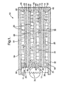
fuel cell stack 10 includes elements known in the art of solid-oxide fuel cell stacks comprising more than one fuel cell. The example shown includes twoidentical fuel cells 11, connected in series, and is of a class of such fuel cells said to be "anode-supported" in that the anode is a structural element having the electrolyte and cathode deposited upon it. Element thicknesses as shown are not to scale. - Each
fuel cell 11 includes anelectrolyte element 14 separating ananodic element 16 and acathodic element 18. Each anode and cathode is in direct chemical contact with its respective surface of the electrolyte, and each anode and cathode has a respectivefree surface respective passageway Anode 16 of onefuel cell 11 faces and is electrically connected to aninterconnect 28 byfilaments 30 extending across but not blockingpassageway 24. Similarly,cathode 18 offuel cell 11 faces and is electrically connected to interconnect 28 byfilaments 30 extending across but not blockingpassageway 26. Similarly,cathode 18 of asecond fuel cell 11 faces and is electrically connected to a cathodiccurrent collector 32 byfilaments 30 extending across but not blockingpassageway 26, andanode 16 offuel cell 11 faces and is electrically connected to an anodiccurrent collector 34 byfilaments 30 extending across but not blockingpassageway 24.Current collectors load 35 in order that thefuel cell stack 10 performs electrical work.Passageways 24 are formed byanode spacers 36 between the perimeter ofanode 16 and eitherinterconnect 28 or anodiccurrent collector 34.Passageways 26 are formed bycathode spacers 38 between the perimeter ofelectrolyte 14 and eitherinterconnect 28 or cathodiccurrent collector 32.Anode spacer 36 andcathode spacer 38 are formed from sheet stock in such a way as to yield the desired height of theanode passageways 24 andcathode passageways 26. - Preferably, the interconnect and the current collectors are formed of an alloy, typically a "superalloy," which is chemically and dimensionally stable at the elevated temperatures necessary for fuel cell operation, generally about 750°C or higher, for example, Hastelloy, Haynes 230, or a stainless steel. The electrolyte is formed of a ceramic oxide and preferably includes zirconia stabilized with yttrium oxide (yttria), known in the art as YSZ. The cathode is formed of, for example, porous lanthanum strontium manganate or lanthanum strontium iron, and the anode is formed of, for example, a mixture of nickel and YSZ.
- In operation (FIG. 1),
reformate gas 21 is provided topassageways 24 at afirst edge 25 of the anodefree surface 20, flows parallel to the surface of the anode across the anode in a first direction, and is removed at a second andopposite edge 29 ofanode surface 20. Hydrogen and CO diffuse into the anode to the interface with the electrolyte.Oxygen 31, typically in air, is provided topassageways 26 at afirst edge 39 of the cathodefree surface 22, flows parallel to the surface of the cathode in a second direction which can be orthogonal to the first direction of the reformate (second direction shown in the same direction as the first for clarity in FIG. 1), and is removed at a second andopposite edge 43 ofcathode surface 22. Molecular oxygen gas (O2) diffuses into the cathode and is catalytically reduced to two O-2 anions by accepting four electrons from the cathode and the cathodiccurrent collector 32 or theinterconnect 28 viafilaments 30. The electrolyte ionically conducts or transports O-2 anions to the anode electrolyte innerface where they combine with four hydrogen atoms to form two water molecules, giving up four electrons to the anode and the anodiccurrent collector 34 or theinterconnect 28 viafilaments 30. Thuscells 11 are connected in series electrically between the two current collectors, and the total voltage and wattage between the current collectors is the sum of the voltage and wattage of the individual cells in a fuel cell stack. - Referring to FIG. 2, a schematic mechanization diagram of a solid-oxide fuel cell system 12 in accordance with the invention includes auxiliary equipment and controls.
- A conventional high speed
inlet air pump 48 draws inlet air 50 through anair filter 52, past afirst MAF sensor 54, through asonic silencer 56, and through a coolingshroud 58 surroundingpump 48. -
Air output 60 frompump 48, at a pressure sensed by pressure sensor 61, is first split into branched conduits between afeed 62 and afeed 72.Feed 62 goes asburner cooling air 64 to atail gas afterburner 66 having anigniter 67 via asecond MAF sensor 68 and a burner coolair control valve 70. -
Feed 72 is further split into branched conduits between ananode air feed 74 and acathode air feed 75.Anode feed 74 goes to ahydrocarbon fuel vaporizer 76 via athird MAF sensor 78 and reformerair control valve 80. A portion ofanode air feed 74 may be controllably diverted bycontrol valve 82 through thecool side 83 of reformatepre-heat heat exchanger 84, then recombined with the non-tempered portion such thatfeed 74 is tempered to a desired temperature on its way tovaporizer 76. Downstream ofvaporizer 76 is a start-upcombustor 77 having anigniter 79. During start-up, when the reformer is cold or well below operating temperature, vaporized fuel is ignited incombustor 77 and the burned gas is passed directly through the reformer to warm the plates therein more rapidly. Obviously, the start-up combustor is deactivated during normal operation of the system. - Cathode air feed 75 is controlled by cathode
air control valve 86 and may be controllably diverted by cathode air preheat bypassvalve 88 through the cool side 90 of cathode airpre-heat heat exchanger 92 on its way tostacks stacks heated air 93 is fed toburner 66. - A hydrocarbon
fuel feed pump 94 draws fuel from astorage tank 96 and delivers the fuel via apressure regulator 98 andfilter 100 to afuel injector 102 which injects the fuel intovaporizer 76. The injected fuel is combined withair feed 74, vaporized, and fed to areformer catalyst 104 inmain fuel reformer 106 which reforms the fuel to, principally, hydrogen and carbon monoxide.Reformate 108 fromcatalyst 104 is fed to the anodes instacks Unconsumed fuel 110 from the anodes is fed to afterburner 66 where it is combined with air supplies 64 and 93 and is burned. When gases are below self ignition temperature, they are ignited byigniter 67. Thehot burner gases 112 are passed through acleanup catalyst 114 inmain reformer 106. The effluent 115 fromcatalyst 114 is passed through the hot sides 116,118 ofheat exchangers effluent 115 is fed to a manifold 120 surroundingstacks - Still referring to FIG. 2, a
first check valve 150 and a firstoxygen getter device 124 are provided in theconduit feeding reformate 108 to the anodes (not visible) instacks second check valve 152 and secondoxygen getter device 126 are similarly provided in the conduit feeding spentreformate 110 from the anodes toafterburner 66. As described above, during cool-down of the fuel cell stacks after shut-down of the assembly, it is important to prevent migration of oxygen intoanode passages 24 whereinanode surface 20, comprising metallic nickel, would be subject to damaging oxidation. Each check valve includes a typical frusto-conical valve seat 154 receptive of avalve ball 156. Preferably, each valve 150,152 is oriented within assembly 12 such that the ball is held in the seat by gravity when reformate is flowed through the system in the forward direction. Thus, fuel flow opens the valve sufficiently for fuel to pass in the forward direction. When assembly 12 is shut down, each valve is closed by gravity. The valves may not be identical, as oxygen flows opposite to the reformate invalve 152, but in the same direction as the reformate invalve 150; the so the balls and seats may require different weights and/or sizes to function as intended. Each getter 124,126 includes apassageway 128 having aninlet 130 and anoutlet 132 through which reformate is passed during operation of the fuel cell assembly. Within the passageway is a readily-oxidized material 134 (oxygen-reducing means), for example, nickel metal foam, nickel wire or nickel mesh, which is capable of gettering oxygen by reaction therewith but which does not present a significant obstruction to flow of reformate through the passageway. Nickel in the getters reacts with oxygen to produce nickel oxide, NiO, when the assembly is shut down, thus protecting the nickel-containing anodes from oxidation. When the assembly is turned back on, reformate is again produced which, in passing through the getters, reduces the NiO back to metallic nickel, allowing the getters to be used repeatedly. - For clarity of presentation and to enhance the reader's understanding, the numbers of elements of the invention as presented further below are grouped in century series depending upon the functional assembly in which the elements occur; therefore, elements recited above and shown in FIGS. 1 and 2 may have different numerical designators when shown and discussed below, e.g., stacks 44,46 become stacks 344,346.
- Referring to FIGS. 3 through 7, in a fuel
cell stack assembly 300 in accordance with the invention, thecells 311 are arranged side-by-side and may comprise a plurality ofcells 311, respectively, such that each offirst stack 344 andsecond stack 346 is a stack ofidentical fuel cells 311. The plurality of cells is preferably about 30 in each of the two stacks. Thecells 311 instack 344 and stack 346 are connected electrically in series byinterconnect 347, and the stacks are connected in series with cathodecurrent collector 332 and anodecurrent collector 334 on the bottom of the stacks. The current collectors are sized to have a "footprint" very close to the same dimension as a cover-sealingflange 340. The current collectors preferably are adhesively sealed to astack mounting plate 338, and the stacks preferably are in turn adhesively sealed to the current collectors. The sealingflange 340 for thecover 342 and top 343 is then mounted and sealed to the current collector plates. Agasket 341 betweenflange 340 and the current collectors is a dielectric so thatflange 340 does not cause a short between the current collectors. Power leads 350,352 are attached to current collectors 332,334, respectively, through strong, reliable and highly conductive metallurgical bonds, such as brazing. In this manner, the current collectors may pass under thecover mounting flange 340, with no additional sealing or power lead attachment required, and do not have to pass undesirably through the cover itself, as in some prior art stack assemblies. Passing leads through the cover makes the assembly more complex and less reliable. - Referring to FIG. 8, a
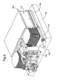
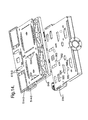
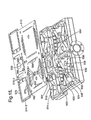
fuel cell assembly 400 in accordance with the invention comprisesstack assembly 300 operatively mounted on an integrated fuel/air manifold assembly 500 which also supports first and second cathode air heat exchangers 600 and an integrated fuel reformer and waste energy recovery unit ("reforWER") 1100.Assembly 400 receives air from air supply system 900 (FIGS. 10-12) as described below and selectively preheats air going to the reformer.ReforWER 1100 reforms hydrocarbon fuel, such as gasoline, into reformate fuel gas comprising mostly hydrogen, carbon monoxide, and lower-molecular weight hydrocarbons, tempers the air and reformate entering the stacks, selectively burns fuel not consumed in the stacks, recovers heat energy generated in various internal processes which would otherwise be wasted, and exhausts spent air and water, all in order to efficiently generate DC electric potential across power leads 350,352 (not visible in FIG. 8). - Referring to FIGS. 9 and 11, there are two basic functions for the enclosure of a fuel cell system. The first is to provide thermal insulation for the components which function at an elevated temperature (700-900°C) to maintain them at that temperature for efficient operation, to protect lower temperature components, and to reduce the exterior temperature over the overall unit to a human-safe level. The second is to provide structural support for mounting of individual components, mounting the system to another structure such as a vehicle, protection of the internal components from the exterior environment, and protection of the surrounding environment from the high temperatures of the fuel cell assembly. Prior art systems utilize a single enclosure to provide all functions, which can be complex and costly to fabricate and assemble, and consumptive of space.
- Still referring to FIGS. 9 and 11, in the present invention, enclosure of the fuel cell assembly comprises two nested enclosures: a
thermal enclosure 700 and astructural enclosure 800.Fuel cell assembly 400 is first disposed in a "clam-shell" typethermal enclosure 700, comprising abottom portion 702 and a top portion 704, which in turn is disposed in astructural enclosure 800. Thesplit line 706 betweenbottom portion 702 and top portion 704 is easily arranged such that all pipes, manifolds, shafts, power leads, etc., which need to pass between the "hot zone" 716 within the thermal enclosure and the "cool zone" 816 within the structural enclosure, do so in the middle ofsplit line 706. This provides for easy assembly of the hot components into the thermal enclosure. First, all hot zone components, included inassembly 400, are nestled into inbottom portion 702, which may be provided with a conforming well 708 for securely holding andcushioning assembly 400, as shown in FIG. 9. Themating surface 710 ofbottom portion 702, alongsplit line 706, is configured as required to accommodate the lower halves of the components extending throughenclosure 700. Top portion 704 is configured to matingly engagebottom portion 702. Top portion 704 is placed ontobottom portion 702 and may be sealed thereto alongline 706 as desired.Thermal enclosure 700 may be formed of any suitable high-temperature high-efficiency insulating material, as is known in the insulating art, and may be a composite including a light-weight metal case. The range of suitable insulating materials is expanded by removing the constraint of overall structural integrity afforded by providing a separatestructural enclosure 800. -
Structural enclosure 800 preferably is fabricated from thicker metal, for example, to provide structural strength and a simple shape, such as a box with a removable lid, for ease of fabrication. Features such as brackets, studs, electrical connectors, studs, weld-nuts, air intake ducts, and exhaust ducts, for example, may be part of the structural enclosure for mounting internal components thereto and for connecting the system to external structures. Features for vibration and shock isolation (not shown) may also be provided with the enclosure. - The
air control assembly 900 is connected to elements offuel cell assembly 400 projecting throughsplit line 706, and assemblies 700,900 are then installed withinstructural enclosure 800, as shown in FIG. 12, to form afuel cell system 1000 in accordance with the invention. Preferably, control system 200 (shown schematically in FIG. 2 aspower conditioner 202, circuit protection l/O 204,drivers 206, andelectronic control unit 208, but not visible in FIG. 12) is also installed onboard the system withincool zone 816 to minimize the number ofdiscrete signals 210 which must be passed throughenclosure 800 viaconnector 820. Note also that high current capacity power leads also pass throughenclosure 800 viadual connectors 821. - Referring to FIGS. 13 through 18, an integrated fuel/
air manifold assembly 500 receives air via flexible bellows elements fromair supply assembly 900 and reformed fuel fromreformer assembly 1100 and conveys high temperature air, exhaust, and hydrogen-rich reformate fuel to and from the core components of the system. Basalmanifold assembly 500 is shown in FIG. 13 as comprising a three-dimensional assembly of three perforated plates and two partitioned elements which are easily and inexpensively formed and which comprise a two-level network of passageways which allow for the mounting, close-coupling, and integration of critical fuel cell system components, including heat exchangers, combustors, fuel reformers, solid-oxide fuel cell stacks, check valves, threaded inserts, and catalyzed and non-catalyzed filters. Of course, while a five-component manifold is shown for simplicity, within the scope of the invention any two of the perforated plates obviously may be incorporated into the partitioned elements, through appropriate and obvious casting or moulding processes, such that the manifold comprises only three elements. - It should be noted that
manifold 500 is actually two mirror image manifolds 500-1,500-2 sharing some common features, for example, cathode air return from the stacks. Thus, reformate fuel flows fromreforWER unit 1100 in two parallel streams tostacks reforWER 1100 in two parallel streams. Likewise, cathode air flow fromair supply assembly 900 is divided into two parallel streams and enters into each manifold 500-1,500-2 via mirror image couplings 902-1 and 902-2 (FIGs. 8-10 and 13).Fuel cell assembly 400 thus is seen to have its fuel cell stacks 344,346 connected in series electrically but serviced by gas flows in parallel. - For simplicity of presentation and discussion, except where functions are unique, the following construction and function is directed to manifold 500-1 but should be understood to be equally applicable to mirror-image manifold 500-2.
-
Bottom plate 502 is the base plate for the manifold and forms the bottom for various chambers formed by combination ofplate 502 with lowerpartitioned element 504, defining alower distribution element 505, as shown in FIG. 16.Intermediate plate 506 completes the chambers inelement 504 and forms the bottom plate for upperpartitioned element 508, defining anupper distribution element 509.Top plate 510 completes the chambers inelement 508 and forms the mounting base forfuel cell assembly 300, heat exchangers 600, andreforWER unit 1100, as described above. - In operation, air enters a first
bottom chamber 512 via coupling 902-1, flows upwards through slots 514-1,514-2,514-3 into heat exchanger 600-1, through the heat exchanger conventionally where the air is heated as described below, downwards through slot 516-3 into a firstupper chamber 518, thence throughopening 520 inplate 506 into a secondlower chamber 522. Inchamber 518, the heated air is controllably mixed with cool air entering the chamber via bypass connection 904-1 fromair supply assembly 900. The tempered air flows upwards fromchamber 522 throughopening 524 inplate 506 into achamber 526 which defines a cathode supply plenum for supplying reaction and cooling air upwards through slottedopenings 528 to the cathode air flow passages instack 344. Spent air is returned from the cathodes via slottedopenings 530 into acathode return plenum 532 and flows downwards through anopening 534 inplate 506 into a common cathodeair return runner 536 leading into a tail-gas combustor 1102 withinreforWER 1100. - Hot reformate from
reforWER 1100 enters manifold 500-1 viaopening 538 intop plate 510 and flows intochamber 540, thence downwards throughopening 542 into afeed runner 544, and upwards throughopening 546 into achamber 548 defining an anode supply plenum forstack 344. - Preferably, opening 546 defines a seat for a valve having a ball 550 (FIG. 14), preferably held in place by gravity, for allowing flow of reformate during operation but preventing flow of oxygen into the anodes when the system is shut down. Further, preferably,
chamber 544 and/or 548 contains an oxygen-reactive material (not shown here but indicated as 134 in FIG. 2), such as nickel wool, through which reformate may easily pass but which can scavenge any oxygen passing byball 550 on its way to the anodes. - Preferably,
cathode supply chamber 522 andanode supply chamber 544 are configured to maximize the area of the common wall between them, such that chambers 522,544 define a co-flow heat exchanger which tends to decrease the temperature difference between the cathode supply air and the anode supply reformate. - From
chamber 548, reformate flows upwards throughslots 552 into the anode flow passages instack 344. Spent reformate ("tail gas") flows downwards throughslots 554 into ananode return plenum 556 and thence downwards throughopening 558 into areformate return runner 560. Fromrunner 560, spent reformate flows upwards throughopening 562 intoelongate chamber 564 common with manifold 500-2 and thence throughopenings 566 into the tail-gas combustor inreforWER 1100. Preferably, opening 562 is also formed as a check valve seat like opening 546 for receiving acheck ball 563 preferably held in place by gravity for preventing reverse flow of oxygen into the anodes when the system is shut down. Further, preferably,chamber 556 and/or 560, likechamber 548, contains an oxygen-reactive material (not shown here but indicated as 134 in FIG. 2), such as nickel wool, through which the tail gas may easily pass but which can scavenge any oxygen passing byball 563 on its way to the anodes. - Burned tail gas from the combustor enters manifold 500-1 via slot 568-3 and flows via slots 568-2,568-1 into
bottom chamber 570 and thence throughopening 572 intochamber 574 which acts as a supply plenum for cathode air heat exchanger 600-1. Burned tail gas flows upward fromchamber 574 throughopenings 576 and through heat exchanger 600-1, thus heating incoming cathode air and partially cooling the tail gas exhaust, returning throughopenings 578 intochamber 580 and thence viaopenings 582 into a tempering jacket space 354 (FIG. 7) surroundingstack 344 between thefuel cells 311 andcover 342. The stack is thus tempered by the exhaust gas. - When the system is running efficiently (>30%), the exhaust gas is considerably cooler than the stack operating temperature; thus the exhaust gas can help to cool the stack with virtually no penalty in pumping energy. This is particularly effective because the exhaust stream has the highest mass flow in the system. Additionally, during start-up of the system, the exhaust gas as it leaves heat exchanger 600-1 is typically hotter than the stack, so the exhaust gas helps to warm the stack and thus shortens the start-up period.
- The burned tail gas returns from
jacket 354 viaopenings 584 into an exhaust plenum comprising openings 586-3,586-2,586-1 which is vented to the atmosphere byexhaust pipe 588 andpipe flange 590. - An
SOFC system 1000 in accordance with the invention is especially useful as an auxiliary power unit (APU) for vehicles 136 (FIG. 12) on which the APU may be mounted, such as cars and trucks, boats and ships, and airplanes, wherein motive power is supplied by a conventional engine and the auxiliary electrical power needs are met by an SOFC system. - An SOFC assembly in accordance with the invention is also useful as a stationary power plant such as, for example, in a household or for commercial usage.
- While the invention has been described by reference to various specific embodiments, it should be understood that numerous changes may be made within the spirit and scope of the inventive concepts described. Accordingly, it is intended that the invention not be limited to the described embodiments, but will have full scope defined by the language of the following claims.
Claims (7)
- A fuel cell system having fuel cells tempered externally by burned tail gas exhaust, comprising:a) a plurality of individual fuel cells organized into at least one fuel cell stack assembly including a plurality of cathodes and anodes;b) means for conveying fuel to said anodes and for returning tail gas fuel from said anodes;c) means for conveying air to said cathodes and for returning air from said cathodes;d) a tempering jacket surrounding said fuel cells in said stack assembly;e) a combustor disposed in said means for returning tail gas fuel for burning said tail gas to produce exhaust gas;f) means for conveying said exhaust gas from said combustor through said tempering jacket; andg) heat exchange means disposed in both said air conveying means and said exhaust conveying means for heating said air and cooling said exhaust gas.
- A fuel cell system in accordance with Claim 1 wherein said fuel cells are solid-oxide fuel cells.
- A fuel cell system in accordance with Claim 1 wherein said system includes a plurality of fuel cell stacks connected electrically in series.
- A fuel cell system in accordance with Claim 1 wherein said system is mounted on a vehicle.
- A fuel cell system in accordance with Claim 4 wherein said vehicle is selected from the group consisting of car, truck, boat, and airplane.
- A fuel cell system in accordance with Claim 5 wherein said system is an auxiliary power unit for said vehicle.
- An automotive vehicle comprising a fuel cell system for generating auxiliary power for said vehicle, said system including fuel cells tempered externally by burned tail gas exhaust,
a plurality of individual fuel cells organized into at least one fuel cell stack assembly including a plurality of cathodes and anodes,
means for conveying fuel to said anodes and for returning tail gas fuel from said anodes,
means for conveying air to said cathodes and for returning air from said cathodes,
a tempering jacket surrounding said fuel cells in said stack assembly,
a combustor disposed in said means for returning tail gas fuel for burning said tail gas to produce exhaust gas,
means for conveying said exhaust gas from said combustor through said tempering jacket, and
heat exchange means disposed in both said air conveying means and said exhaust conveying means for heating said air and cooling said exhaust gas.
Applications Claiming Priority (2)
| Application Number | Priority Date | Filing Date | Title |
|---|---|---|---|
| US178855 | 2002-06-24 | ||
| US10/178,855 US7588849B2 (en) | 2002-06-24 | 2002-06-24 | Solid-oxide fuel cell system having tempering of fuel cell stacks by exhaust gas |
Publications (2)
| Publication Number | Publication Date |
|---|---|
| EP1394883A1 true EP1394883A1 (en) | 2004-03-03 |
| EP1394883B1 EP1394883B1 (en) | 2006-07-12 |
Family
ID=29734792
Family Applications (1)
| Application Number | Title | Priority Date | Filing Date |
|---|---|---|---|
| EP03076576A Expired - Fee Related EP1394883B1 (en) | 2002-06-24 | 2003-05-23 | Solid-oxide fuel cell system having tempering of fuel cell stacks by exhaust gas |
Country Status (3)
| Country | Link |
|---|---|
| US (1) | US7588849B2 (en) |
| EP (1) | EP1394883B1 (en) |
| DE (1) | DE60306725T2 (en) |
Cited By (3)
| Publication number | Priority date | Publication date | Assignee | Title |
|---|---|---|---|---|
| GB2462849A (en) * | 2008-08-21 | 2010-02-24 | Ceres Ip Co Ltd | Improved fuel cell stack flow hood air flow using an air distribution device |
| WO2010020797A1 (en) | 2008-08-21 | 2010-02-25 | Ceres Intellectual Property Company Limited | Improved fuel cell stack flow hood air flow using an air distribution device |
| WO2013104396A1 (en) * | 2012-01-10 | 2013-07-18 | Daimler Ag | Fuel cell stack |
Families Citing this family (15)
| Publication number | Priority date | Publication date | Assignee | Title |
|---|---|---|---|---|
| JP3994825B2 (en) * | 2002-08-28 | 2007-10-24 | ダイキン工業株式会社 | Fuel cell power generation system |
| CA2464546A1 (en) * | 2003-04-18 | 2004-10-18 | Coen Company, Inc. | Fuel cell anode gas oxidizing apparatus and process |
| FI121444B (en) * | 2005-01-03 | 2010-11-15 | Waertsilae Finland Oy | Device and process in a fuel cell plant |
| US9190693B2 (en) | 2006-01-23 | 2015-11-17 | Bloom Energy Corporation | Modular fuel cell system |
| US7659022B2 (en) | 2006-08-14 | 2010-02-09 | Modine Manufacturing Company | Integrated solid oxide fuel cell and fuel processor |
| FI119490B (en) * | 2006-06-22 | 2008-11-28 | Waertsilae Finland Oy | Preheating arrangement in fuel cell equipment |
| US8241801B2 (en) * | 2006-08-14 | 2012-08-14 | Modine Manufacturing Company | Integrated solid oxide fuel cell and fuel processor |
| US8968958B2 (en) | 2008-07-08 | 2015-03-03 | Bloom Energy Corporation | Voltage lead jumper connected fuel cell columns |
| DE102011078115A1 (en) * | 2011-06-27 | 2012-12-27 | Siemens Aktiengesellschaft | High-temperature energy storage device and method for thermally insulating a high-temperature chamber with a high-temperature energy storage |
| FR2985522B1 (en) * | 2012-01-09 | 2014-03-14 | Commissariat Energie Atomique | INSTALLATION OF HIGH TEMPERATURE WATER VAPOR ELECTROLYSIS (HVAC) WITH ALLOTHERMIC PRODUCTION OF HYDROGEN |
| US9461328B1 (en) | 2012-08-20 | 2016-10-04 | Ballard Power Systems Inc. | Solid oxide fuel cell power plant having a bootstrap start-up system |
| KR102371046B1 (en) * | 2016-07-15 | 2022-03-07 | 현대자동차주식회사 | End cell heater for fuel cell |
| KR20220127238A (en) | 2019-12-20 | 2022-09-19 | 세인트-고바인 세라믹스 앤드 플라스틱스, 인크. | Apparatus comprising an electrochemical device and a heat exchanger |
| US11566589B2 (en) * | 2021-01-20 | 2023-01-31 | International Engine Intellectual Property Company, Llc | Exhaust gas recirculation cooler barrier layer |
| DE102021214812A1 (en) | 2021-12-21 | 2023-06-22 | Robert Bosch Gesellschaft mit beschränkter Haftung | fuel cell device |
Citations (5)
| Publication number | Priority date | Publication date | Assignee | Title |
|---|---|---|---|---|
| EP0328812A1 (en) * | 1988-02-16 | 1989-08-23 | Westinghouse Electric Corporation | Electrochemical generators of rectangular design having corner heating |
| DE4037970A1 (en) * | 1989-12-21 | 1991-06-27 | Asea Brown Boveri | Automatic start-up of high-temp. hydrocarbon fuel cells - involves preheating of fuel and air by combustion with natural convection assistance in afterburner above stack |
| JPH03156859A (en) * | 1989-11-15 | 1991-07-04 | Nkk Corp | Solid electrolyte fuel cell power generating system |
| US5340664A (en) * | 1993-09-29 | 1994-08-23 | Ceramatec, Inc. | Thermally integrated heat exchange system for solid oxide electrolyte systems |
| US20010049035A1 (en) * | 2000-05-01 | 2001-12-06 | Haltiner Karl Jacob | Solid oxide fuel cell process gas sampling for analysis |
Family Cites Families (7)
| Publication number | Priority date | Publication date | Assignee | Title |
|---|---|---|---|---|
| US3718506A (en) * | 1971-02-22 | 1973-02-27 | Bbc Brown Boveri & Cie | Fuel cell system for reacting hydrocarbons |
| NL8800252A (en) | 1988-02-02 | 1989-09-01 | Veg Gasinstituut Nv | Carrier catalyst for non-selective oxidation of organic compounds, process for non-selective oxidation of, in particular, organic compounds. |
| US5968680A (en) * | 1997-09-10 | 1999-10-19 | Alliedsignal, Inc. | Hybrid electrical power system |
| JP2001518688A (en) * | 1997-10-01 | 2001-10-16 | アキュメントリクス・コーポレーション | Integrated solid oxygen fuel cell and improved machine |
| US6361891B1 (en) * | 1999-12-20 | 2002-03-26 | Utc Fuel Cells, Llc | Direct antifreeze cooled fuel cell power plant system |
| US6756144B2 (en) * | 2002-01-03 | 2004-06-29 | Hybrid Power Generation Systems, Llc | Integrated recuperation loop in fuel cell stack |
| US7279246B2 (en) * | 2002-06-24 | 2007-10-09 | Delphi Technologies, Inc. | Solid-oxide fuel cell system having an integrated air/fuel manifold |
-
2002
- 2002-06-24 US US10/178,855 patent/US7588849B2/en not_active Expired - Fee Related
-
2003
- 2003-05-23 DE DE60306725T patent/DE60306725T2/en not_active Expired - Lifetime
- 2003-05-23 EP EP03076576A patent/EP1394883B1/en not_active Expired - Fee Related
Patent Citations (5)
| Publication number | Priority date | Publication date | Assignee | Title |
|---|---|---|---|---|
| EP0328812A1 (en) * | 1988-02-16 | 1989-08-23 | Westinghouse Electric Corporation | Electrochemical generators of rectangular design having corner heating |
| JPH03156859A (en) * | 1989-11-15 | 1991-07-04 | Nkk Corp | Solid electrolyte fuel cell power generating system |
| DE4037970A1 (en) * | 1989-12-21 | 1991-06-27 | Asea Brown Boveri | Automatic start-up of high-temp. hydrocarbon fuel cells - involves preheating of fuel and air by combustion with natural convection assistance in afterburner above stack |
| US5340664A (en) * | 1993-09-29 | 1994-08-23 | Ceramatec, Inc. | Thermally integrated heat exchange system for solid oxide electrolyte systems |
| US20010049035A1 (en) * | 2000-05-01 | 2001-12-06 | Haltiner Karl Jacob | Solid oxide fuel cell process gas sampling for analysis |
Non-Patent Citations (1)
| Title |
|---|
| PATENT ABSTRACTS OF JAPAN vol. 015, no. 390 (E - 1118) 3 October 1991 (1991-10-03) * |
Cited By (6)
| Publication number | Priority date | Publication date | Assignee | Title |
|---|---|---|---|---|
| GB2462849A (en) * | 2008-08-21 | 2010-02-24 | Ceres Ip Co Ltd | Improved fuel cell stack flow hood air flow using an air distribution device |
| WO2010020797A1 (en) | 2008-08-21 | 2010-02-25 | Ceres Intellectual Property Company Limited | Improved fuel cell stack flow hood air flow using an air distribution device |
| GB2462849B (en) * | 2008-08-21 | 2012-03-07 | Ceres Ip Co Ltd | Improved fuel cell stack flow hood air flow using an air distribution device |
| US9093674B2 (en) | 2008-08-21 | 2015-07-28 | Ceres Intellectual Property Company Limited | Fuel cell stack flow hood air flow using an air distribution device |
| WO2013104396A1 (en) * | 2012-01-10 | 2013-07-18 | Daimler Ag | Fuel cell stack |
| US9406964B2 (en) | 2012-01-10 | 2016-08-02 | Daimler Ag | Fuel cell stack |
Also Published As
| Publication number | Publication date |
|---|---|
| US20030235733A1 (en) | 2003-12-25 |
| EP1394883B1 (en) | 2006-07-12 |
| US7588849B2 (en) | 2009-09-15 |
| DE60306725T2 (en) | 2007-07-12 |
| DE60306725D1 (en) | 2006-08-24 |
Similar Documents
| Publication | Publication Date | Title |
|---|---|---|
| US6942942B2 (en) | Solid-oxide fuel cell assembly having a thermal enclosure within a structural enclosure | |
| EP1401042B1 (en) | Solid-oxide fuel cell system having means for controlling tail gas combustion temperature | |
| US6608463B1 (en) | Solid-oxide fuel cell system having an integrated air supply system | |
| US6921596B2 (en) | Solid-oxide fuel cell system having an integrated reformer and waste energy recovery system | |
| EP1387427B1 (en) | Solid-oxide fuel cell system having a heat exchanger regulating the temperature of the cathode air feed | |
| EP1414092B1 (en) | Solid-oxide fuel cell system having an integrated air/fuel manifold | |
| EP1394883B1 (en) | Solid-oxide fuel cell system having tempering of fuel cell stacks by exhaust gas | |
| US6967064B2 (en) | Co-flow anode/cathode supply heat exchanger for a solid-oxide fuel cell assembly | |
| US6627339B2 (en) | Fuel cell stack integrated with a waste energy recovery system | |
| EP1403955B2 (en) | Solid-oxide fuel cell assembly having an electronic control unit within a structural enclosure | |
| EP1418637B1 (en) | Solid-oxide fuel cell assembly having simplified arrangement of current collectors | |
| US7410016B2 (en) | Solid-oxide fuel cell system having a fuel combustor to pre-heat reformer on start-up | |
| US7537849B2 (en) | Solid-oxide fuel cell assembly having a convectively vented structural enclosure | |
| EP1522114B1 (en) | Oxygen isolation and collection for anode protection in a solid-oxide fuel cell stack | |
| EP1376725B1 (en) | Mass flow metering air supply for a solid-oxide fuel cell stack |
Legal Events
| Date | Code | Title | Description |
|---|---|---|---|
| PUAI | Public reference made under article 153(3) epc to a published international application that has entered the european phase |
Free format text: ORIGINAL CODE: 0009012 |
|
| AK | Designated contracting states |
Kind code of ref document: A1 Designated state(s): AT BE BG CH CY CZ DE DK EE ES FI FR GB GR HU IE IT LI LU MC NL PT RO SE SI SK TR |
|
| AX | Request for extension of the european patent |
Extension state: AL LT LV MK |
|
| 17P | Request for examination filed |
Effective date: 20040903 |
|
| 17Q | First examination report despatched |
Effective date: 20041001 |
|
| AKX | Designation fees paid |
Designated state(s): DE FR GB |
|
| GRAP | Despatch of communication of intention to grant a patent |
Free format text: ORIGINAL CODE: EPIDOSNIGR1 |
|
| GRAS | Grant fee paid |
Free format text: ORIGINAL CODE: EPIDOSNIGR3 |
|
| GRAA | (expected) grant |
Free format text: ORIGINAL CODE: 0009210 |
|
| AK | Designated contracting states |
Kind code of ref document: B1 Designated state(s): DE FR GB |
|
| REG | Reference to a national code |
Ref country code: GB Ref legal event code: FG4D |
|
| REF | Corresponds to: |
Ref document number: 60306725 Country of ref document: DE Date of ref document: 20060824 Kind code of ref document: P |
|
| ET | Fr: translation filed | ||
| PLBE | No opposition filed within time limit |
Free format text: ORIGINAL CODE: 0009261 |
|
| STAA | Information on the status of an ep patent application or granted ep patent |
Free format text: STATUS: NO OPPOSITION FILED WITHIN TIME LIMIT |
|
| 26N | No opposition filed |
Effective date: 20070413 |
|
| GBPC | Gb: european patent ceased through non-payment of renewal fee |
Effective date: 20070523 |
|
| PG25 | Lapsed in a contracting state [announced via postgrant information from national office to epo] |
Ref country code: GB Free format text: LAPSE BECAUSE OF NON-PAYMENT OF DUE FEES Effective date: 20070523 |
|
| PGFP | Annual fee paid to national office [announced via postgrant information from national office to epo] |
Ref country code: FR Payment date: 20140519 Year of fee payment: 12 Ref country code: DE Payment date: 20140529 Year of fee payment: 12 |
|
| REG | Reference to a national code |
Ref country code: DE Ref legal event code: R119 Ref document number: 60306725 Country of ref document: DE |
|
| REG | Reference to a national code |
Ref country code: FR Ref legal event code: ST Effective date: 20160129 |
|
| PG25 | Lapsed in a contracting state [announced via postgrant information from national office to epo] |
Ref country code: DE Free format text: LAPSE BECAUSE OF NON-PAYMENT OF DUE FEES Effective date: 20151201 |
|
| PG25 | Lapsed in a contracting state [announced via postgrant information from national office to epo] |
Ref country code: FR Free format text: LAPSE BECAUSE OF NON-PAYMENT OF DUE FEES Effective date: 20150601 |