EP1394787A2 - Optical disc and optical disc apparatus - Google Patents
Optical disc and optical disc apparatus Download PDFInfo
- Publication number
- EP1394787A2 EP1394787A2 EP03019195A EP03019195A EP1394787A2 EP 1394787 A2 EP1394787 A2 EP 1394787A2 EP 03019195 A EP03019195 A EP 03019195A EP 03019195 A EP03019195 A EP 03019195A EP 1394787 A2 EP1394787 A2 EP 1394787A2
- Authority
- EP
- European Patent Office
- Prior art keywords
- light transmission
- transmission layer
- layer
- range
- optical disk
- Prior art date
- Legal status (The legal status is an assumption and is not a legal conclusion. Google has not performed a legal analysis and makes no representation as to the accuracy of the status listed.)
- Withdrawn
Links
Images




Classifications
-
- G—PHYSICS
- G11—INFORMATION STORAGE
- G11B—INFORMATION STORAGE BASED ON RELATIVE MOVEMENT BETWEEN RECORD CARRIER AND TRANSDUCER
- G11B7/00—Recording or reproducing by optical means, e.g. recording using a thermal beam of optical radiation by modifying optical properties or the physical structure, reproducing using an optical beam at lower power by sensing optical properties; Record carriers therefor
- G11B7/24—Record carriers characterised by shape, structure or physical properties, or by the selection of the material
- G11B7/24018—Laminated discs
- G11B7/24027—Layers; Shape, structure or physical properties thereof
-
- G—PHYSICS
- G11—INFORMATION STORAGE
- G11B—INFORMATION STORAGE BASED ON RELATIVE MOVEMENT BETWEEN RECORD CARRIER AND TRANSDUCER
- G11B7/00—Recording or reproducing by optical means, e.g. recording using a thermal beam of optical radiation by modifying optical properties or the physical structure, reproducing using an optical beam at lower power by sensing optical properties; Record carriers therefor
- G11B7/24—Record carriers characterised by shape, structure or physical properties, or by the selection of the material
- G11B7/2403—Layers; Shape, structure or physical properties thereof
- G11B7/24056—Light transmission layers lying on the light entrance side and being thinner than the substrate, e.g. specially adapted for Blu-ray® discs
-
- G—PHYSICS
- G11—INFORMATION STORAGE
- G11B—INFORMATION STORAGE BASED ON RELATIVE MOVEMENT BETWEEN RECORD CARRIER AND TRANSDUCER
- G11B7/00—Recording or reproducing by optical means, e.g. recording using a thermal beam of optical radiation by modifying optical properties or the physical structure, reproducing using an optical beam at lower power by sensing optical properties; Record carriers therefor
- G11B7/004—Recording, reproducing or erasing methods; Read, write or erase circuits therefor
-
- G—PHYSICS
- G11—INFORMATION STORAGE
- G11B—INFORMATION STORAGE BASED ON RELATIVE MOVEMENT BETWEEN RECORD CARRIER AND TRANSDUCER
- G11B7/00—Recording or reproducing by optical means, e.g. recording using a thermal beam of optical radiation by modifying optical properties or the physical structure, reproducing using an optical beam at lower power by sensing optical properties; Record carriers therefor
- G11B7/24—Record carriers characterised by shape, structure or physical properties, or by the selection of the material
- G11B7/241—Record carriers characterised by shape, structure or physical properties, or by the selection of the material characterised by the selection of the material
- G11B7/252—Record carriers characterised by shape, structure or physical properties, or by the selection of the material characterised by the selection of the material of layers other than recording layers
- G11B7/253—Record carriers characterised by shape, structure or physical properties, or by the selection of the material characterised by the selection of the material of layers other than recording layers of substrates
- G11B7/2533—Record carriers characterised by shape, structure or physical properties, or by the selection of the material characterised by the selection of the material of layers other than recording layers of substrates comprising resins
- G11B7/2534—Record carriers characterised by shape, structure or physical properties, or by the selection of the material characterised by the selection of the material of layers other than recording layers of substrates comprising resins polycarbonates [PC]
Definitions
- the present invention relates to an optical disk capable of high density recording.
- a DVD is constructed in such a way that an information recording layer is formed on a transparent substrate (hereafter, referred to as a light transmission layer) having a thickness of 0.6 mm, and laser light is allowed to pass through the light transmission layer to converge on the information recording surface to write or read information.
- the numerical aperture (NA) of an objective lens for converging a beam of this time is 0.6 as a reference.
- the reference of the thickness of the light transmission layer of a DVD is 0.6 mm as described above, it is unavoidable that a thickness dispersion occurs from the viewpoint of manufacturing of disks.
- the light transmission layer is designed in such a way that the standard value of the thickness thereof is 0.6 mm, if the thickness of a substrate is manufactured departing from 0.6 mm, aberration occurs. Since such aberration of an optical system increases a beam spot diameter and adversely affects reproduction of a signal, it is necessary to restrain the aberration to a predetermined value or less from the viewpoint of the system.
- the aberration of the optical system due to a thickness error of the light transmission layer is determined by both a deviation from a standard value of the light transmission layer and a deviation from a standard value of the refractive index of the light transmission layer. Accordingly, in the case of a DVD, in order to restrain the aberration of the optical system caused by a thickness error of the light transmission layer to a constant value or less, the range of the light transmission layer thickness is specified as a two-dimensional range of the light transmission layer thickness and the refractive index thereof. This range is disclosed for example in Jpn. Pat. Appln. KOKAI Publication No. 8-273199.
- n 1.45 to 1.65
- the error of the light transmission layer thickness with respect to the standard value is ⁇ 0.03 mm
- a horizontal axis represents the refractive index
- a vertical axis represents the light transmission layer thickness
- n becomes smaller than a lens load specification (standard value)
- a range which is shifted in a direction in which the light transmission layer thickness is increased is specified, and if it becomes larger, a range by which the light transmission layer thickness is not changed is specified.
- the spot size of focused light emitted on the information recording surface of an optical disk is in proportion to the wavelength and is in inverse proportion to the NA showing the iris angle of an objective lens for focusing light. Accordingly, in order to contract the spot size of focused light, aiming at improving the recording density, it is necessary to shorten the light source wavelength and increase the NA of the objective lens.
- the refractive index of the light transmission layer is dependent upon the light source wavelength, it is necessary to newly specify the range of the light transmission layer thickness as a two-dimensional range with its refractive index.
- An embodiment of the present invention is to provide an optical disk suitable for a high density recording, which specifies the range of the light transmission layer thickness and the refractive index of the light transmission layer available for a next generation optical disk.
- the wavelength of the laser light which is incident onto the light transmission layer is set within the range of 395 to 415 nm and the constant A 1 is 0.26200, constant A 2 is -0.32400, and constant A 3 is 0.00595.
- FIG. 1 shows one example of a cross-sectional view of an optical disk 1 of the present invention.
- An information recording layer 3 including for example a phase change recording film is formed on (under in the figure) a substrate 2 made of polycarbonate.
- an information recording layer 3 made of a metal reflective film instead of the phase change recording film is formed.
- a light transmitting layer 4 having a thickness of t is formed on (under in the figure) the information recording layer 3.
- the light transmitting layer 4 is for example polycarbonate.
- FIG. 2 shows an example of the formation of an optical disk apparatus for recording and reproducing data on the present disk.
- a semiconductor laser 20 of a short wavelength is employed as a light source.
- the wavelength of the emitted light is that of violet wavelength band generally of the range of 395 nm to 415 nm (405 ⁇ 10 nm).
- the light 100 emitted from the semiconductor laser light source 20 becomes parallel light by means of a collimator lens 21 and passes through a polarizing beamsplitter 22 and a ⁇ /4 plate 23 to enter an objective lens 25.
- the range of the NA of the objective lens is for example 0.6 to 0.7.
- the emitted light 100 passes through the light transmission layer 4 of the optical disk 1 and is focused on the information recording layer 3.
- Reflected light 101 by the information recording layer 3 of the optical disk 1 passes through the light transmitting layer 4 of the optical disk 1 again to pass through an objective lens 25 and the ⁇ /4 plate 23 and is reflected by means of the polarizing beam-splitter 22 to pass through a photo detection optical system 26 to enter a photo detector 27.
- a light receiving portion of the photo detector 27 is generally divided into plural portions, and each light receiving portion outputs current in response to light intensity.
- the output current after being converted into a voltage by an unillustrated I/V amplifier, is arithmetically processed into a RF signal, a focus error signal, and a track error signal by a data processing unit 29.
- a servo driver 28 drives a lens drive coil 12 to move the lens 25 in a focus direction (lens optical axis direction) and a tracking direction (disk radius direction). As a result, a beam spot is generated on a target track of the information recording layer 3.
- the apparatus when the thickness of the light transmission layer 4 falls into a standard value (for example, 0.6 mm), the apparatus has been designed in such a manner that the light enters the objective lens 25 as approximately parallel light.
- a standard value for example, 0.6 mm
- a spherical aberration caused by a thickness error of the light transmission layer 4 occurs.
- convergent spot shape on the information recording layer 3 of the optical disk 1 is distorted, stable, correct recording and reproducing becomes difficult.
- the optical disk 1 of the present invention is characterized by having the range of the thickness error and the refractive index of the light transmission layer 4 which is obtained by considering the trend of shortening the wavelength and_increasing the NA in an optical disk apparatus.
- FIG. 3 shows a manner in which the light beam 100 is focused on the recording layer 3 employing an ideal objective lens to which aberration is completely compensated with respect to the lens load in which in the light transmission layer of an optical disk the refractive index is 1.60 and the thickness is 0.6 mm so that a beam spot is generated.
- wave front is in order, and wave front aberration, that is, curvature of wave front does not occur.
- wave front aberration occurs due to residual spherical aberration of the lens system and the like, an ideal beam spot does not occur as shown by dotted curved lines 6 in the drawing.
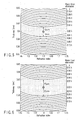
- FIG. 4 shows results obtained by calculation of rms (root mean square) values of wave front aberrations which occur in the case where optical disks 1 having various light transmission layer refractive indexes n and light transmission layer thicknesses t are employed instead of the above-described ideal objective lens.
- the horizontal axis represents the light transmission layer refractive index n'.and the vertical axis represents the light transmission layer thickness t
- rms values of wave front aberrations at each point on the coordinates plane are displayed by contour lines.
- the range of the refractive indexes and thicknesses of the light transmission layers of optical disks according to one embodiment of the present invention is the range shown in FIG. 5. This shows the following area.
- Refractive index n 1.45 ⁇ n ⁇ 1.75
- contour lines of the wave front aberration amounts of FIG. 4 line up approximately parallel to'the vertical axis direction, and their curved lines can be shown as curved lines obtained by imparting a constant offset to equation (3) given above. Accordingly, when acceptable values of aberrations are determined, the range of the light transmission layer thicknesses and the refractive indexes can be determined through the equations (1) to (3) by making the acceptable values correspond to offset t1, t2.
- the acceptable values of aberrations are values determined according to performance or acceptable aberrations of an optical disk apparatus which performs recording or reproducing on an optical disk.
- the range of the'refractive index is determined by the material of the light transmission layer 2 and the wavelength of the light source, and a range in which an effective material as the material of the light transmission layer of an optical disk is contained is specified.
- the refractive index in violet wavelength band of an effective material, such as polycarbonate, as the light transmission layer of an optical disk can be covered.
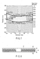
- the range of the thickness and the refractive index of the light transmission layer of an optical disk according to another embodiment of the present invention has a range shown in FIG. 7.
- This range although being approximately similar to the range of the optical disk of the embodiment shown in FIG. 5, is an area which is not encircled by curved lines but is encircled by straight lines. Its effect is similar to that of the optical disk of the embodiment described above.
- the range of the thickness and the refractive index of the light transmission layer of an optical disk according to another embodiment of the present invention is shown in FIG. 11.
- the range of the thickness and the refractive index of the light transmission layer although being defined by values which partly differ from those of FIG. 7, is not largely different therefrom. That is, the range is defined at the points of the refractive indexes 1.5 and 1.7.
- This embodiment has a similar effect that the refractive index can be covered in violet wavelength band of a material, such as polycarbonate and the like, which is effective as the light transmission layer of an optical disk.
- FIG. 8 shows an example of a cross-sectional view of an optical disk 51 according to another embodiment of the present invention.
- An information recording layer 53 including for example a phase change recording film on (under'in the drawing) a substrate 52 made of polycarbonate is formed.
- a space layer 54 having transparency is formed thereon, and another 'information recording layer 55 is formed further thereon.
- the information recording layers 53 and 55 may be layers for the exclusive use of reproduction, both of which are made of metallic reflection films, and both may be recordable and reproducible layers, or only one of which may be a reproduction-only layer and another of which may be recordable and reproducible layer.
- a light transmission layer 56 is formed on the information recording layer 55.
- the light transmission layer 56 is for example made of polycarbonate.
- a substrate 52 for example on which the information recording layer 53 is formed and the light transmission layer 56 on which the information recording layer 54 is formed are glued via a pressure sensitive adhesive such as a ultraviolet ray setting resin (to be the space layer 54).
- the role of the space layer 54 is to optically shut out information leak (cross talk) from another information recording layer when one side information recording layer is reproduced.
- the interval of the two information recording layers is better to be as large as possible, and the thickness of the space layer 54 is better to be thick.
- a load is put on a recording and reproducing optical system. That is, in the case where the thickness from the surface of the light transmission layer to the center of the space layer is specified as the load of the objective lens, even if either one of information recording layers is recorded and reproduced, aberration due to the thickness error of half the thickness of the space layer occurs. Accordingly, in view of the aberration of the recording and reproducing optical system, the thickness of the space layer is better to be thin. That is, the thickness of the space layer is set to a compromise point of trade off relationship in the cross talk of the information recording layer and the aberration of the recording/reproducing optical system.
- the thickness of the space layer is about 20 ⁇ m to 30 ⁇ m, considering the trade off. It is better to represent a thickness specification of the light transmission layer of a two layer disk by a minimum value of the thickness of the light transmission layer 56 and a maximum value of the sum of thicknesses of the light transmission layer 56, the information recording layer 55 in contact with this light transmission layer, and the space layer 54.
- the range of the thickness and the refractive index of the light transmission layer of the optical disk at this time becomes the range shown in FIG. 9.
- the lens load in which the refractive index of the light transmission layer of the optical disk is 1.60 and the thickness is 0.6 mm and that acceptable aberration of the system is 0.05 ⁇ .
- the specified area is the area shown below:
- the acceptable aberration is set to 0.05 ⁇ , considering the thickness of the space layer, the range of the thickness direction is widened compared to the case of single layer.
- the refractive index of the space layer is set within the range of +0.0 to -0.15 of the refractive index of the light transmission layer 56.
- the range of the thickness and the refractive index of the light transmission layer of an optical disk of another embodiment of the present invention has the range shown in FIG. 10.
- This range although being- substantially similar to the range of the optical disk of the embodiment shown in FIG. 9, is an area which is not encircled by curved lines but is encircled by straight lines. 'Its effect is similar to that of the optical disk of the embodiment described above.
- the range of the thickness and the refractive index of the light transmission layer of an optical disk according to another embodiment of the present invention is shown in FIG. 12.
- the range of the thickness and the refractive index of the light transmission layer is defined by values which are partly different from those in FIG. 10, the range is not largely different therefrom. That is, the range is defined at the points of the refractive indexes 1.5 and 1.7.
- This embodiment has a similar effect that the refractive index can be covered in violet wavelength band of a material, such as polycarbonate and the like, which is effective as the light transmission layer of an optical disk.
- the three embodiments show the cases where the information recording layer are two layers, 'it is needless to say that the embodiments can be' applied to an optical disk having two or more information recording layers.
- the present invention it is possible to specify the range of the light transmission layer thickness and the light transmission layer refractive index which is effective in a next generation disk and to provide an optical disk which is suitable for a high density recording.
Landscapes
- Optical Record Carriers And Manufacture Thereof (AREA)
- Optical Head (AREA)
Abstract
Description
That is, with respect to the range of the refractive index, n = 1.45 to 1.65, in the case where the error of the light transmission layer thickness with respect to the standard value is ±0.03 mm, when a horizontal axis represents the refractive index and a vertical axis represents the light transmission layer thickness,
if the refractive index n becomes smaller than a lens load specification (standard value), a range which is shifted in a direction in which the light transmission layer thickness is increased is specified, and if it becomes larger, a range by which the light transmission layer thickness is not changed is specified.
A2 = -0.32400
A3 = 0.00595
t1, t2 = 13 (µm)
t1, t2 = 22 µm
f(n) is according to equation (3).
Claims (18)
- An optical disk (1) which is constructed in such a manner that an information recording layer (3) formed on a substrate (4) is covered with a light transmission layer (2) and in which the range of the thickness and the refractive index of the light transmission layer is set so that aberration due to. a deviation of the thickness and the refractive-index of the light transmission layer from each standard value falls within the range of certain acceptable values, characterized in that
the thickness t of the light transmission layer is set within the range of f(n) - t1 ≤ t < f(n) + t2, employing function f(n) of the refractive index n of the light transmission layer and constants t1, t2 determined based on an acceptable value of aberration in the light transmission layer,
the refractive index of the light transmission layer is set within the range of 1.45 to 1.75,
the numerical aperture of a lens emitting laser light which is incident onto the light transmission layer is set to 0.65, and
the function f(n) is shown by - The optical disk according to claim 1, characterized in that the refractive index of the light transmission layer is set within the range of 1.5 to 1.7.
- The optical disk according to claim 1, characterized in that the wavelength of the laser light which is incident onto the light transmission layer is set within the range of 395 to 415 nm.
- The optical disk according to claim 1, characterized in that the constant A1 is 0.26200, constant A2 is -0.32400, and constant A3 is 0.00595.
- The optical disk according to claim 1, characterized in that minimum values of the constants t1, t2 are substantially set to 10 µm.
- The optical disk according to claim 1, characterized in that the constants t1, t2 are substantially set to 13 µm.
- The optical disk according to claim 1, characterized in that predetermined positions on curved lines that f(n) - t1 and f(n) + t2 show are sampled, and an area encircled by connecting each sample point by means of straight lines is set as the range of the thickness t of the light transmission layer.
- An optical disk which is constructed in such a manner that a plurality of information recording layers (53, 55) are laminated by sandwiching a space layer (54) having a light transmission property therebetween on a substrate (1) and are covered with alight transmission layer (52), characterized in that
the thickness t of the light transmission layer is set to f(n) - t1 or more, employing function f(n) of the refractive index n of the light transmission layer and constants t1, t2 determined based on an acceptable value of aberration in the layer comprising the light transmission layer, the information recording layers, and the space layer,
the sum of thicknesses of the light transmission layer, the space layer, and the information recording layer excluding the information recording layer which is closest to the substrate is set to f(n) + t2 or less,
the refractive index of the light transmission layer is set within the range of 1.45 to 1.75,
the refractive index of the space layer is set within the range of +0.0 to -0.15 of the refractive index of the light transmission layer,
the numerical aperture of a lens emitting laser light which is incident onto the light transmission layer is set to 0.65, and
the function f(n) is shown by - The optical disk according to claim 8, characterized in that the refractive index of the light transmission layer is set within the range of 1.5 to 1.7.
- The optical disk according to claim 8, characterized in that the wavelength of the laser light which is incident onto the light transmission layer is set within the range of 395 to 415 nm.
- The optical disk according to claim 8, characterized in that the constant A1 is 0.26200, constant A2 is -0.32400, and constant A3 is 0.00595.
- The optical disk according to claim 8, characterized in that minimum values of the constants t1, t2 are substantially set to 10 µm.
- The optical disk according to claim 8, characterized in that the constants t1, t2 are substantially set to 22 µm.
- The optical disk according to claim 8, characterized in that predetermined positions on a curved line that f(n) - t1 shows are sampled so that the thickness that a straight line connecting each sample point shows is set to a minimum value of the thickness t of the light transmission layer in a corresponding refractive index, and
predetermined positions on a curved line that f(n) + t2 shows are sampled so that the thickness that a straight line connecting each sample point shows is set to a maximum value of the thickness of the sum of the light transmission layer in a corresponding refractive index, the space layer, and the information recording layer excluding the information recording layer which is closest to the substrate. - An optical disk apparatus characterized by comprising:a semiconductor laser element emitting laser light whose wavelength is 395 to 415; anda processing unit allowing the laser light from the semiconductor laser element to be emitted to the optical disk to perform recording processing and reproducing processing, for an optical disk (1) which is constructed in such a manner that an information recording layer (3) formed on a substrate (4) is covered with a light transmission layer (2) and in which 'the range of the thickness and the refractive index of the light transmission layer is set so that aberration due to a deviation of the thickness and the refractive index of the light transmission layer from each standard value falls within the range of certain acceptable values, characterized in thatthe thickness t of the light transmission layer is set within the range of f(n) - t1 ≤ t ≤ f(n) + t2, employing function f(n) of the refractive index n of the light transmission layer and constants t1, t2 determined based on an acceptable value of aberration in the light transmission layer,the refractive index of the light transmission layer is set within the range of 1.45 to 1.75,the numerical aperture of a lens emitting laser light which is incident onto the light transmission layer is set to 0.65, andthe function f(n) is shown by
- The optical disk apparatus according to claim 15, characterized in that the refractive index of the light transmission layer is set within the range of 1.5 to 1.7.
- An optical disk apparatus characterized by comprising:a semiconductor laser element emitting laser light whose wavelength is 395 to 415 nm; anda processing unit allowing the laser light from the semiconductor laser element to be emitted to the optical disk to perform recording processing and reproducing processing, for an optical disk (1) which is constructed in such a manner that a plurality of information recording layers (53, 55) are laminated by sandwiching a space layer (54) having a light transmission property therebetween on a substrate (1) and are covered with a light transmission layer (52), characterized in thatthe thickness t of the light transmission layer is set to f(n) - t1 or more, employing function f(n) of the refractive index n of the light transmission layer and constants t1, t2 determined based on an acceptable value of aberration in the layer comprising the light transmission layer, the information recording layers, and the space layer,the sum of thicknesses of the light transmission layer, the space layer, and the information recording layer excluding the information recording layer which is closest to the substrate is set to f(n) + t2 or less,the refractive index of the light transmission layer is set within the range of 1.45 to 1.75,the refractive index of the space layer is set within the range of ±0.1 of the refractive index of the light transmission layer,the numerical aperture of a lens emitting laser light which is incident onto the light transmission layer is set to 0.65, andthe function f(n) is shown by
- The optical disk apparatus according to claim 17, characterized in that the refractive index of the light transmission layer is set within the range of 1.5 to 1.7.
Applications Claiming Priority (6)
| Application Number | Priority Date | Filing Date | Title |
|---|---|---|---|
| JP2002249202A JP2004087043A (en) | 2002-08-28 | 2002-08-28 | Optical disk and optical disk device |
| JP2002249202 | 2002-08-28 | ||
| JP2003096300 | 2003-03-31 | ||
| JP2003096300 | 2003-03-31 | ||
| JP2003161032 | 2003-06-05 | ||
| JP2003161032A JP2004355785A (en) | 2003-03-31 | 2003-06-05 | Optical disk and optical disk device |
Publications (2)
| Publication Number | Publication Date |
|---|---|
| EP1394787A2 true EP1394787A2 (en) | 2004-03-03 |
| EP1394787A3 EP1394787A3 (en) | 2006-11-22 |
Family
ID=31499126
Family Applications (1)
| Application Number | Title | Priority Date | Filing Date |
|---|---|---|---|
| EP03019195A Withdrawn EP1394787A3 (en) | 2002-08-28 | 2003-08-25 | Optical disc and optical disc apparatus |
Country Status (5)
| Country | Link |
|---|---|
| US (2) | US20040090902A1 (en) |
| EP (1) | EP1394787A3 (en) |
| KR (1) | KR100572159B1 (en) |
| CN (1) | CN1265369C (en) |
| TW (1) | TWI228251B (en) |
Families Citing this family (5)
| Publication number | Priority date | Publication date | Assignee | Title |
|---|---|---|---|---|
| US7133331B2 (en) * | 2000-12-28 | 2006-11-07 | Victor Company Of Japan, Limited | Recording medium having a substrate containing microscopic pattern of parallel groove and land sections and recording/reproducing equipment therefor |
| JP2006018877A (en) * | 2004-06-30 | 2006-01-19 | Toshiba Corp | Optical disk device |
| KR101104218B1 (en) * | 2009-07-10 | 2012-01-09 | 황인성 | Framed Glyph Doors |
| WO2021145017A1 (en) * | 2020-01-15 | 2021-07-22 | パナソニックIpマネジメント株式会社 | Optical disk, manufacturing method thereof, optical information device, and information processing method |
| US11892409B1 (en) | 2022-10-25 | 2024-02-06 | Taiwan Redeye Biomedical Inc. | Discrete light detection device |
Family Cites Families (12)
| Publication number | Priority date | Publication date | Assignee | Title |
|---|---|---|---|---|
| US5677903A (en) * | 1991-03-25 | 1997-10-14 | U.S. Phillips Corporation | Multi-layer information storage system with improved aberration correction |
| JPH08273199A (en) | 1995-01-31 | 1996-10-18 | Toshiba Corp | Optical disk and optical disk device |
| JPH10302310A (en) * | 1997-04-25 | 1998-11-13 | Sony Corp | Optical recording medium and optical disk device |
| KR100316772B1 (en) | 1998-04-09 | 2002-01-16 | 윤종용 | Optical recording medium |
| JP4258037B2 (en) * | 1998-06-29 | 2009-04-30 | ソニー株式会社 | Optical recording medium and optical recording / reproducing apparatus using the same |
| JP2000123416A (en) | 1998-10-14 | 2000-04-28 | Sony Corp | Optical recording medium and optical recording / reproducing device |
| JP4164984B2 (en) | 2000-03-27 | 2008-10-15 | ソニー株式会社 | Optical recording medium |
| CN1204556C (en) | 2000-10-03 | 2005-06-01 | 松下电器产业株式会社 | optical information recording medium |
| JP2002133719A (en) * | 2000-10-27 | 2002-05-10 | Pioneer Electronic Corp | Optical recording medium |
| JP2002163830A (en) | 2000-11-24 | 2002-06-07 | Toshiba Corp | Optical information processing system using optical aberration and information medium having recording layer protected by transparent layer with uneven thickness |
| TW583660B (en) | 2001-01-25 | 2004-04-11 | Koninkl Philips Electronics Nv | Optical information medium and a method of manufacturing the medium |
| JP2003173572A (en) * | 2001-12-06 | 2003-06-20 | Toshiba Corp | Optical disc and its recording / reproducing device |
-
2003
- 2003-08-25 EP EP03019195A patent/EP1394787A3/en not_active Withdrawn
- 2003-08-26 TW TW092123490A patent/TWI228251B/en not_active IP Right Cessation
- 2003-08-27 KR KR1020030059441A patent/KR100572159B1/en not_active Expired - Fee Related
- 2003-08-28 US US10/650,132 patent/US20040090902A1/en not_active Abandoned
- 2003-08-28 CN CNB031553850A patent/CN1265369C/en not_active Expired - Fee Related
-
2006
- 2006-09-28 US US11/528,579 patent/US7283447B2/en not_active Expired - Fee Related
Non-Patent Citations (1)
| Title |
|---|
| None * |
Also Published As
| Publication number | Publication date |
|---|---|
| US20070019532A1 (en) | 2007-01-25 |
| KR20040019946A (en) | 2004-03-06 |
| KR100572159B1 (en) | 2006-04-19 |
| EP1394787A3 (en) | 2006-11-22 |
| TWI228251B (en) | 2005-02-21 |
| TW200405300A (en) | 2004-04-01 |
| US20040090902A1 (en) | 2004-05-13 |
| CN1494070A (en) | 2004-05-05 |
| CN1265369C (en) | 2006-07-19 |
| US7283447B2 (en) | 2007-10-16 |
Similar Documents
| Publication | Publication Date | Title |
|---|---|---|
| EP0855701B1 (en) | Optical pickup compatible with recordable compact disk and digital video disk using plane parallel plates | |
| KR100230253B1 (en) | Object lens device and manufacturing method thereof and optical pickup using it | |
| JP2002245656A (en) | Two-position imaging objective lens for optical pickup | |
| US6859429B2 (en) | Aberration correcting unit, optical pickup apparatus, and recording/reproducing apparatus | |
| JP2002055274A (en) | Objective lens for optical recording medium and optical pickup device using the same | |
| EP1724771A1 (en) | Optical recording and reproducing apparatus, optical head, optical recording and reproducing method and skew detection method | |
| US6278670B1 (en) | Optical head apparatus | |
| US7283447B2 (en) | Optical disc and optical disc apparatus | |
| US7038978B2 (en) | Optical information recording and reproducing apparatus for recording information bits into an optical disk in a three dimensional arrangement | |
| JP2005535063A (en) | Scanning device including an objective lens formed of two kinds of materials | |
| EP1318510A2 (en) | Optical disk and recording/reproducing apparatus | |
| JP2004259439A (en) | Optical disc and its recording / reproducing device | |
| US20090109825A1 (en) | Optical scanning device | |
| US20060067204A1 (en) | Objective lens and scanning device using such an objective lens | |
| JP2001013406A (en) | Objective lens and optical pickup device using the same | |
| JPH10255306A (en) | Optical pickup device | |
| JP2004087043A (en) | Optical disk and optical disk device | |
| JP2004355785A (en) | Optical disk and optical disk device | |
| JP2005100647A (en) | Optical disc and optical disc apparatus | |
| JP2005267849A (en) | Optical disc and optical disc apparatus | |
| KR100562338B1 (en) | Optical pickup | |
| JPH103686A (en) | Information pickup device and objective lens therefor | |
| US20070111142A1 (en) | Optical disk and recording/reproducing apparatus | |
| KR20030071070A (en) | Structure for photo diode optical pick-up | |
| JP2005166257A (en) | Optical information recording medium |
Legal Events
| Date | Code | Title | Description |
|---|---|---|---|
| PUAI | Public reference made under article 153(3) epc to a published international application that has entered the european phase |
Free format text: ORIGINAL CODE: 0009012 |
|
| 17P | Request for examination filed |
Effective date: 20030825 |
|
| AK | Designated contracting states |
Kind code of ref document: A2 Designated state(s): AT BE BG CH CY CZ DE DK EE ES FI FR GB GR HU IE IT LI LU MC NL PT RO SE SI SK TR |
|
| AX | Request for extension of the european patent |
Extension state: AL LT LV MK |
|
| PUAL | Search report despatched |
Free format text: ORIGINAL CODE: 0009013 |
|
| AK | Designated contracting states |
Kind code of ref document: A3 Designated state(s): AT BE BG CH CY CZ DE DK EE ES FI FR GB GR HU IE IT LI LU MC NL PT RO SE SI SK TR |
|
| AX | Request for extension of the european patent |
Extension state: AL LT LV MK |
|
| 17Q | First examination report despatched |
Effective date: 20061227 |
|
| AKX | Designation fees paid |
Designated state(s): AT BE BG CH CY CZ DE DK EE ES FI FR GB GR HU IE IT LI LU MC NL PT RO SE SI SK TR |
|
| STAA | Information on the status of an ep patent application or granted ep patent |
Free format text: STATUS: THE APPLICATION IS DEEMED TO BE WITHDRAWN |
|
| 18D | Application deemed to be withdrawn |
Effective date: 20100302 |