EP1394761A2 - Obstacle detection device and method therefor - Google Patents
Obstacle detection device and method therefor Download PDFInfo
- Publication number
- EP1394761A2 EP1394761A2 EP03255358A EP03255358A EP1394761A2 EP 1394761 A2 EP1394761 A2 EP 1394761A2 EP 03255358 A EP03255358 A EP 03255358A EP 03255358 A EP03255358 A EP 03255358A EP 1394761 A2 EP1394761 A2 EP 1394761A2
- Authority
- EP
- European Patent Office
- Prior art keywords
- detection
- obstacle
- slope degree
- corresponding points
- image
- Prior art date
- Legal status (The legal status is an assumption and is not a legal conclusion. Google has not performed a legal analysis and makes no representation as to the accuracy of the status listed.)
- Granted
Links
Images





Classifications
-
- G—PHYSICS
- G08—SIGNALLING
- G08G—TRAFFIC CONTROL SYSTEMS
- G08G1/00—Traffic control systems for road vehicles
- G08G1/16—Anti-collision systems
- G08G1/165—Anti-collision systems for passive traffic, e.g. including static obstacles, trees
-
- G—PHYSICS
- G06—COMPUTING OR CALCULATING; COUNTING
- G06T—IMAGE DATA PROCESSING OR GENERATION, IN GENERAL
- G06T7/00—Image analysis
- G06T7/50—Depth or shape recovery
- G06T7/55—Depth or shape recovery from multiple images
- G06T7/593—Depth or shape recovery from multiple images from stereo images
-
- G—PHYSICS
- G06—COMPUTING OR CALCULATING; COUNTING
- G06T—IMAGE DATA PROCESSING OR GENERATION, IN GENERAL
- G06T7/00—Image analysis
- G06T7/70—Determining position or orientation of objects or cameras
-
- G—PHYSICS
- G06—COMPUTING OR CALCULATING; COUNTING
- G06T—IMAGE DATA PROCESSING OR GENERATION, IN GENERAL
- G06T7/00—Image analysis
- G06T7/70—Determining position or orientation of objects or cameras
- G06T7/73—Determining position or orientation of objects or cameras using feature-based methods
- G06T7/74—Determining position or orientation of objects or cameras using feature-based methods involving reference images or patches
-
- G—PHYSICS
- G06—COMPUTING OR CALCULATING; COUNTING
- G06V—IMAGE OR VIDEO RECOGNITION OR UNDERSTANDING
- G06V20/00—Scenes; Scene-specific elements
- G06V20/10—Terrestrial scenes
-
- G—PHYSICS
- G06—COMPUTING OR CALCULATING; COUNTING
- G06V—IMAGE OR VIDEO RECOGNITION OR UNDERSTANDING
- G06V20/00—Scenes; Scene-specific elements
- G06V20/10—Terrestrial scenes
- G06V20/182—Network patterns, e.g. roads or rivers
-
- G—PHYSICS
- G06—COMPUTING OR CALCULATING; COUNTING
- G06V—IMAGE OR VIDEO RECOGNITION OR UNDERSTANDING
- G06V20/00—Scenes; Scene-specific elements
- G06V20/50—Context or environment of the image
- G06V20/56—Context or environment of the image exterior to a vehicle by using sensors mounted on the vehicle
- G06V20/58—Recognition of moving objects or obstacles, e.g. vehicles or pedestrians; Recognition of traffic objects, e.g. traffic signs, traffic lights or roads
-
- G—PHYSICS
- G06—COMPUTING OR CALCULATING; COUNTING
- G06V—IMAGE OR VIDEO RECOGNITION OR UNDERSTANDING
- G06V20/00—Scenes; Scene-specific elements
- G06V20/50—Context or environment of the image
- G06V20/56—Context or environment of the image exterior to a vehicle by using sensors mounted on the vehicle
- G06V20/588—Recognition of the road, e.g. of lane markings; Recognition of the vehicle driving pattern in relation to the road
-
- G—PHYSICS
- G08—SIGNALLING
- G08G—TRAFFIC CONTROL SYSTEMS
- G08G1/00—Traffic control systems for road vehicles
- G08G1/16—Anti-collision systems
- G08G1/166—Anti-collision systems for active traffic, e.g. moving vehicles, pedestrians, bikes
-
- G—PHYSICS
- G06—COMPUTING OR CALCULATING; COUNTING
- G06T—IMAGE DATA PROCESSING OR GENERATION, IN GENERAL
- G06T2207/00—Indexing scheme for image analysis or image enhancement
- G06T2207/10—Image acquisition modality
- G06T2207/10016—Video; Image sequence
- G06T2207/10021—Stereoscopic video; Stereoscopic image sequence
-
- G—PHYSICS
- G06—COMPUTING OR CALCULATING; COUNTING
- G06T—IMAGE DATA PROCESSING OR GENERATION, IN GENERAL
- G06T2207/00—Indexing scheme for image analysis or image enhancement
- G06T2207/30—Subject of image; Context of image processing
- G06T2207/30248—Vehicle exterior or interior
- G06T2207/30252—Vehicle exterior; Vicinity of vehicle
- G06T2207/30261—Obstacle
Definitions
- the present invention relates to an obstacle detection device for detecting any obstacles on a road without confusing those with textures using a plurality of cameras mounted in a vehicle or provided above the road, and a method applied to the device.
- the obstacles are those located on the road such as other vehicles ahead, parked vehicles, and pedestrians.
- the textures include white lines, road signs, paint, road stains, and shadows of roadside objects, all of which do not disturb vehicle driving.
- the cameras are provided mainly for helping safe driving and realizing automatic driving of the vehicle, or for counting the number of passing vehicles on the road or monitoring those passing vehicles for their driving. Obstacle detection is possible even if the relationship between the road plane and the respective cameras constantly changes in relative position or posture due to camera vibration or a change in road tilt, for example.
- Amethod for detecting any obstacles on roads is classified into two types: one is a type using active sensors typified by sonars, radars, and range finders; and the other is a type using passive sensors typified by visible-light CCD cameras and infrared cameras.
- the active sensors are popular for measuring object positions in various applications, and well known for their usability.
- the active sensors have, however, problems for an application of detecting any obstacles lying in the vehicles' way on the roads such as other vehicles. Specifically, the problems are associated with low detection resolution, not enough measurement range, erroneous detection of non-obstacles on the roads, and erroneous detection of objects lying on non-disturbing road side due to no driving lane detection capability.
- image brightness intensity pattern or driving lanes recognized for the purpose.
- driving lanes cutting out parts in shades of gray with less texture will do from images picked up by a camera.
- stereoscopic views With stereoscopic views, three-dimensional (3D) information about a target detection region can be derived on the triangulation principle.
- 3D three-dimensional
- stereoscopic views seem to be a solution for obstacle and lane detection with higher accuracy, but still bear problems.
- a corresponding point search cannot be uniquely solved, and the calculation cost is quite expensive. This corresponding point search is done to find any specific point(s) in real world shared by a plurality of camera images.
- Patent Literature 1 JP-A-2000-293693
- Patent Literature 2 JP-A-2001-761278
- the equation 2 shows a parameter dependent on the positions and postures of the right and left cameras with respect to the road plane, lens focal distances of the cameras, points of origin of the images, and the like.
- a corresponding point P'(u', v') on the left image is derived based on the assumption that an arbitrary point P(u, v) on the right image is located on the road plane.
- the points P and P' are paired as the correct corresponding points, leading to a good match between two pixels or neighboring regions in terms of brightness intensity or feature.
- the points P and P' differ in brightness intensity, the point P is determined as belonging to an obstacle region. This method allows for determining whether an arbitrary point in the image has a height from the road plane directly only from the relational expression 1. There is thus no need for the corresponding point search between the right and left images.
- the parameter h is presumed as roughly constant when the vehicle is driving on rather flat road at low speed. Thus, there is no need to calculate the parameter h twice for correct obstacle detection.
- the correspondence detection section operates to convert a first image picked up by a first image pick-up device into an image viewed from a viewpoint of a second image pick-up device.
- a parameter used for this conversion is so calculated as to keep a typical geometric relationship between a plurality of image pick-up devices and the road plane, with a presumption that the vehicle is standing still on the no-tilting road plane.
- the parameter is not calculated twice, and not changed during obstacle detection, e.g., when the vehicle is moving.
- the parameter is calculated in a manner based on the Patent Literature 1, and described in the below.
- two cameras a and b are set up.
- the road surface has two parallel white lines 1 and 1' extending roughly along the optical axes of the cameras.
- the obstacle detection device is not notified of the relationship between the two cameras a and b in position and posture, but only of epipolar constraint.
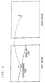
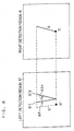
- the epipolar constraint means a constraint condition for stereoscopic images of a general type. Under this condition, as shown in FIG.
- the arbitrary point P on the image (right image) picked up by the camera a is so constrained as to be on a predetermined linear line including the corresponding point P' on the image (left image) picked up by the camera b.
- This linear line is referred to as an epipolar line.
- the epipolar line agrees with the scanning line.
- the epipolar constraint is dependent on the relationship between the stereoscopic cameras in relative position and posture, and internal parameters of the cameras, e.g., lens focal distance, origin point of images.
- the epipolar constraint being invariant means the relative positional relationship between the stereoscopic cameras and their internal parameters showing no change (during when the obstacle detection device is in operation or the vehicle having the device mounted therein is moving).
- (u, v) is the arbitrary point P on the right image
- (u', v') is the corresponding point of the point P on the left image.
- the equation 4 denotes an epipolar line corresponding to the point P(u, v) on the right image.
- Nine elements of the matrix F are not all independent, and theoretically, are derivable from seven corresponding points. Because 3D position is not required for each pair of the corresponding points, calculating the matrix F, i.e., the epipolar constraint, is rather easy.
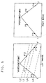
- the lines l and l' in each image are parallel three-dimensionally but not on the images picked up by the right and left cameras. As shown in FIG.
- the lines l and l' in each image cross each other at a point at infinity, which is called a vanishing point.
- derived is a relationship established between the corresponding points on the road plane.
- arbitrary points on the linear line l are P 1 and P 3
- arbitrary points on the linear line l' are P 2 and P 4 .
- corresponding points P 1 ', P 2 ', P 3 ', and P 4 ' in the left image can be calculated using the epipolar constraint previously derived. That is, the point P 1 ' correspond to the point P 1 agrees with an intersection point of the linear line l and the epipolar line L 1 of the point P 1 on the left image.
- the points P 2 ', P 3 ', and P 4 ' can be derived as intersections, respectively, of the epipolar lines L 2 , L 3 , and L 4 of the points P 2 , P 3 , and P 4 , and the linear line l or l' .
- the relation between the coordinates (u i , v i ) and (u i ', v i ') can be expressed by a relational expression 5.
- u ' h 11 u + h 12 v + h 13 h 31 u + h 32 u + h 33
- v ' h 21 u + h 22 v + h 23 h 31 u + h 32 u + h 33
- Patent Literatures 1 and 2 when the vehicle drives on typical outside roads, the relationship between the road plane and the respective cameras continuously changes in relative position and posture due to vibrations occurring to the obstacle detection device, or a change in road tilt. Consequently, these methods bear such problems, due to vehicle vibration, as frequent erroneous detection especially around the texture on the road plane such as white lines, road signs, paint, road stains, shadows of roadside objects and vehicles, and the like.
- the present invention is proposed in consideration of the above conventional problems, and an object thereof is to provide an obstacle detection device capable of correctly detecting only true obstacles no matter what road the device is set up, or no matter what road a vehicle having the device mounted therein is driving.
- An embodiment of the present invention is an obstacle detection device in which at least two image pick-up devices each pick up an image of a preset common detection region, and which determines whether an obstacle is present or not in the detection region from stereo images picked up using the image pick-up devices.
- the device includes: image input means for receiving the image from each of the image pick-up devices; correspondence detection means for deriving a plurality of pairs of corresponding points in the detection regions of the received two stereo images; slope degree calculation means for calculating a slope degree corresponding to a slope angle between a basic plane which is parallel to optical axes of the image pick-up devices and a detection plane including the derived plurality of corresponding points in the stereo images; and result determination means for determining as there being an obstacle when the slope degree of the detection plane is larger than a predetermined value.
- the slope degree calculation means regards the slope angle as a pitch angle between the basic plane and the detection plane, and a parameter of an affine transformation matrix indicating a relationship between the corresponding points in the images or a unique value derived from the parameter as a slope degree.
- the slope degree calculation means calculates the slope degree by solving an equation based on a parallax and vertical positions of the plurality of pairs of corresponding points.
- the slope degree calculation means calculates the slope degree by voting coordinate values of the plurality of pairs of corresponding points into a voting space based on an equation satisfied by the coordinate values.
- the slope degree calculation means detects, as an obstacle, out of the plurality of pairs of corresponding points, only the pair of corresponding points resulting in the slope degree large in value.
- An embodiment of the present invention is directed to an obstacle detection method in which at least two image pick-up devices each pick up an image of a preset common detection region, and which determines whether an obstacle is present or not in the detection region from stereo images picked up using the image pick-up device.
- the method includes: an image receiving step of receiving the image from each of the image pick-up devices; a correlation detecting step of deriving a plurality of pairs of corresponding points in the detection regions of the two stereo images; a slope degree calculating step of calculating a slope degree corresponding to a slope angle between a basic plane which in parallel to optical axes of the image pick-up devices and a detection plane including the derived plurality of corresponding points in the stereo images; and a result determining step of determining as there being an obstacle when the slope degree of the detection plane is larger than a predetermined value.
- An embodiment of the present invention is a program for realizing, by computer execution, an obstacle detection method in which at least two image pick-up devices each pick up an image of a preset common detection region, and which determines whether an obstacle is present or not in the detection region from stereo images picked up using the image pick-up device.
- the program realizes: an image input function for receiving the image from each of the image pick-up devices; a correspondence detection function for deriving a plurality of pairs of corresponding points in the detection regions of the two stereo images; a slope degree calculation function for calculating a slope degree corresponding to a slope angle between a basic plane which is parallel to both of optical axes of the image pick-up devices and a detection plane including the derived plurality of corresponding points in the stereo images; and a result determination function for determining as there being an obstacle when the slope degree of the detection plane is larger than a predetermined value.
- An embodiment of the present invention is an obstacle detection device in which at least two image pick-up devices each pick up an image of a preset common detection region, and a determination is made from stereo images picked up using the image pick-up devices whether or not the detection region includes an obstacle.
- an image input section for receiving the stereo images from the image pick-up devices; a correspondence detection section for deriving a plurality of pairs of corresponding points in the detection regions of the received stereo images; a slope degree calculation section for calculating a slope degree corresponding to a slope angle between a basic plane which is parallel to optical axes of the image pick-up devices and a detection plane including the derived plurality of corresponding points of the stereo images; and a result determination section for determining as there being an obstacle when the slope degree of the detection plane is larger than a predetermined value.
- An embodiment of the present invention is a recording medium having recorded a program for realizing, by computer execution, an obstacle detection method in which at least two image pick-up devices each pick up an image of a preset common detection region, and a determination is made from stereo images picked up using the image pick-up devices whether or not the detection region includes an obstacle.
- an image input function for receiving the stereo images from the image pick-up devices; a correspondence detection function for deriving a plurality of pairs of corresponding points in the detection regions of the received stereo images; a slope degree calculation function for calculating a slope degree corresponding to a slope angle between a basic plane which is parallel to optical axes of the image pick-up devices and a detection plane including the derived plurality of corresponding points in the stereo images; and a result determination function for determining as there being an obstacle when the slope degree of the detection plane is larger than a predetermined value.
- FIGS. 1, 2, and 6 to 14 An embodiment of the present invention is described by referring to FIGS. 1, 2, and 6 to 14.
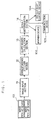
- FIG. 1 is a schematic diagram showing the structure of an obstacle detection device 10 of the present embodiment.
- the obstacle detection device 10 is structured by an image input section 11, a correspondence detection section 12, a slope degree calculation section 13, and a result determination section 14.
- a warning device 102 may warn a driver or a supervisor. Further, if the obstacle detection device 10 is mounted in a vehicle, vehicle body control means 103 may be provided for braking. Alternatively, vehicle braking by steering is a possibility. In any case, a communications device 104, or the like, may be provided to receive any output or transferred result.
- the image input section 11 the correspondence detection section 12, the slope degree calculation section 13, and the result determination section 14 are functionally realized by computer-stored programs.
- the image input section 11 receives images from arbitrary number of image pick-up devices 101.
- the image pick-up device 101 exemplified by a CCD camera are plurally provided.
- two of the devices are mounted in a vehicle, as shown in FIG. 2, those are attached to the front part of the vehicle, on the right and left sides. If two are provided above a road, as shown in FIG. 3, those are so provided as to face in the direction the road is extending.
- the optical axes of these two image pick-up devices 101 are parallel to each other.
- the image input section 11 subjects, to A/D conversion, video signals coming from a plurality of image pick-up devices. Then, the A/D conversion result is stored in memory of the image input section 11 as digital images or image sequences. In response to a request, the images of arbitrary time and arbitrary region are output to the correspondence detection section 12 in the following stage.
- the correspondence detection section 12 performs corresponding point search with respect to the images picked up by the image pick-up devices 101 and stored in the image input section 11.
- the corresponding point search is done to find any specific point(s) in real world shared by the images picked up by the cameras.
- thus found corresponding points are used for calculating a slope degree in the slope degree calculation section 13 in the next stage.
- 3D structure reconstruction is not done by the general stereoscopic image processing.
- the corresponding point search is not necessarily strictly done, and any simpler method requiring less calculation can be used.
- right image an image picked up by the right camera and stored in the image input section 11
- left image an image picked up by the left camera at the same time
- arbitrary pixels or arbitrary regions in the right image are calculated for their predetermined feature quantities. Any pixel or region large in feature quantity is selected as a feature point of the right image.
- the "feature quantity” denotes arbitrary information derivable for each pixel or in an arbitrary region. Possibly used as the feature quantity are simply a pixel brightness intensity value or color information, or an arbitrary scalar or vector calculatable from results derived by arbitrary object detection or a region segmentation process such as differentiation or integration result in space or time, arbitrary filter superposition result, or mean or variance statistic, or calculatable from images such as feature quantities or movement quantities of a region derived by these results. In this example, described is a case where the feature quantity is a brightness intensity pitch at a pixel position.
- the "intensity gradient” denotes a degree of brightness intensity change in the vicinity of the pixels, and the closer to the boundary regions, i.e., edges, of objects or object structures in images, the larger the value gets.
- a filter such as a Sobel operator may be applied to a target image.
- a brightness intensity value of a pixel (x, y) is I(x, y)
- D (x, y) is a brightness intensity pitch value in the vertical direction
- 2M+1 is the filter size.
- Non-patent Literature 1 (edited by Takagi and Shimoda, Image Analysis Handbook, Tokyo University Press, ISBN4-13-061107-0).
- Methods for calculating a matching level between arbitrary pixels or arbitrary regions is called matching, and typified by template matching.
- template matching a region in the vicinity of the feature point in the image is used as a template, and the template is compared to an arbitrary part of the target search region in the image to find a region showing a tight match.
- a template region K
- a brightness intensity value of a template pixel is T(i, j) (in this embodiment, the region in the vicinity of the feature point derived for the right image)
- a brightness intensity value of the pixel in the search region is I(x, y) (in this embodiment, the search region set for the feature point in the left image).
- the corresponding point is located on an epipolar line.
- the search region of the corresponding point is limited onto the epipolar line, thereby reducing calculating task for the corresponding point search.
- the epipolar line agrees with the scanning line, making the corresponding point search easier.
- Non-Patent Reference 1 shows details about well-known methods.
- a plurality of corresponding points in the left image may be searched for one feature point in the right image.
- Such a corresponding point search is applicable not only to original images, i.e., brightness intensity value images, but also to images as a result of the arbitrary feature quantity calculation described in the above.
- the slope degree calculation section 13 uses pairs of corresponding points in the right and left images derived by the correspondence detection section 12 to find a slope degree corresponding to a slope angle of a plane in a 3D space in the detection region (in the below, referred to as detection plane).
- the "slope angle” is an angle between the road plane and the detection plane, and is a pitch angle with respect to the road plane, having small yaw and roll angles. Details are left for later description.
- the road plane is a plane (basic plane) which is parallel to optical axes of two image pick-up devices 101.
- the slope angle is not a tilt to a horizontal plane but a tilt to the road plane. Even if a vehicle having the image pick-up device 101 mounted therein is driving on a road plane tilted against the horizontal plane, i.e., slope, the "slope angle" between the road plane and a plane parallel thereto is 0 degree.
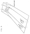
- the pitch angle is a slope angle ⁇ in the vertical direction forming with two image pick-up devices 101, as shown in FIG. 9.
- the yaw angle is a tilt in the horizontal direction, that is, the yaw angle is 0 degree if the road is straight.
- the roll angle is a tilt about an optical axis, that is, the roll angle is 0 degree with the horizontal plane.
- slope angle and “slope degree” are different, and a slope degree changes with respect to a slope angle. Details will be described later.
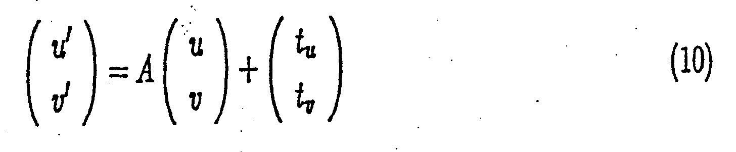
- A denotes a 2 ⁇ 2 affine transformation matrix
- (t u , t v ) T denotes a vector indicating translation.
- parallax d ⁇ v + t v
- ⁇ v is dependent on v
- ⁇ d is a parallax element generated by ⁇ v but not dependent on v, being constant in the local region.
- the fluctuation value ⁇ in the detection region of ⁇ can be derived.
- derived fluctuation value ⁇ is the "slope degree" as will be described later.
- the fluctuation value ⁇ is a factor for determining whether or not the detection region include any obstacle therein.
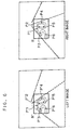
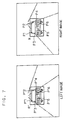
- FIG. 6 is a schematic diagram showing a case where image regions R and R' are previously set in the right and left images as both detection regions. Both detection regions each include white lines and a road sign, but no obstacle.
- FIG. 7 shows an exemplary result of finding corresponding points in the region R' with respect to feature points in the region R including an obstacle.
- FIG. 6 focus on a line segment P 2 P 5 in the region R and the corresponding line segment P 2 'P 5 ' in the region R'.
- FIG. 8 shows enlarged version of these line segments as s and s 1 ', s corresponding to P 2 P 5 , and s 1 ' to P 2 ' P 5 .
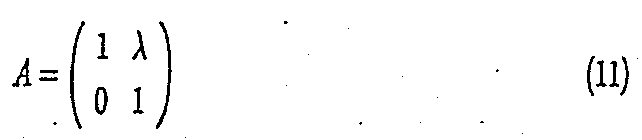
- the line segment s' in the left region R' is a result of converting the line segment s by the affine transformation equation 10 based on the approximation of the equation 11.
- the reason why the line segment s' in the image has a different tilt from the line segment s is that
- FIG. 7 focus on a line segment P 1 P 3 in the region R and the corresponding line segment P 1 'P 3 ' in the region R'.
- FIG. 8 shows enlarged version of these line segments as s and s 2 '.
- the line segment s is not located on the road plane, and thus the line segment s 2 ' corresponding thereto has a different angle from the line segment s' derived by subjecting the line segment s to affine transformation. That is, to transform the line segment s to s 2 ', the transformation should be carried out in such a manner as to laterally displace points on the line segment by an amount proportional to v.
- Described above is a case of calculating ⁇ using a line segment between two corresponding points on the detection plane in the detection region.
- the affine transformation parameter is derived utilizing a fact that the parallax d in the equation 13 is dependent only on a v coordinate of a feature point. This is equivalent of deriving a pitch angle (i.e., slope angle) from a road plane (i.e., basic plane) in the detection region, in which the detection region is a plane in 3D space or a part thereof (this is the detection plane).
- a pitch angle i.e., slope angle
- yaw and roll angles other than the pitch angle are presumed as being sufficiently small.
- the slope angle of the detection plane corresponds to ⁇ in FIG. 9.
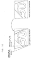
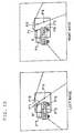
- Approximation such as the equation 11 is applicable to a case where only the slope angle ⁇ changes. If this is the case, in FIG. 10, the equation 10 means that the rectangular detection region in the right image is transformed into a parallelogram in the left image. Displacement occurring at the time of such a transformation is dependent, directly, on the size of ⁇ + ⁇ , and the actual cause is the size of ⁇ .
- the detection region is transformed into a parallelogram of intermediate state considering road being horizontal and obstacle being vertical.
- ⁇ will take an intermediate value between 0 and - ⁇ . Accordingly, by solving the equation 13, derived is the value ⁇ showing a monotonous change depending on the size of the slope angle ⁇ .
- the rectangle is transformed into a parallelogram using approximation of the equation 11. Accordingly, the feature points and corresponding points do not necessarily aligned on the linear lines, but only need to be located on some plane.
- ⁇ is a quantity derived depending on the slope angle ⁇ of the detection plane, and ⁇ can be forwarded to the result determination section 14 in the next stage as the slope degree.
- the detection region includes m feature points, and for each thereof, n corresponding point at the maximum, mxn pairs of corresponding points can be derived at the maximum. Solving the equation 13 derived from all of these pairs will lead to ⁇ . The equation can be solved using two pairs of corresponding points, but three or more pairs will make the equation redundant. Thus, a statistical technique such as least square is effective to derive ⁇ with higher accuracy.
- Solving the equation 13 is equivalent of deriving an intersection point of lines derived from a plurality of pairs of corresponding points.
- the equation 13 is regarded as a linear line in ⁇ d- ⁇ space.
- the ⁇ d- ⁇ space is divided into a plurality of square cells, and when a line passes though the cells, the corresponding cells are increased in value.
- a process is referred to as voting process. After subjecting such a voting process to every possible line, finding a cell position showing the largest value leads to ⁇ .
- Such a method is effective even if not all the lines intersect at a point, and if a plurality of maximum values are found, the cell position showing the largest value leads to ⁇ , for example.
- the distribution result may be forwarded to the next result determination section 14 as the distribution of the slope degrees.
- a detection region is extending over an obstacle and a road plane, and feature points and corresponding points are detected both on the obstacle (P 1 , P 3 , P 6 , P 1 ', P 3 ', and P 6 ') and the road plane (P 2 , P 4 , P 2 ', and P 4 ') , or detection of some corresponding points have gone wrong (P 5 , and P 5 ').
- the result determination section 14 refers to the slope degree of the detection region or a distribution thereof derived by the slope degree detection section 13, and determines whether or not the detection region includes any obstacle.
- ⁇ calculated by the slope degree calculation section 13 shows a monotonous change depending on the slope angle of the detection region.
- ⁇ is roughly equal to 0
- ⁇ is roughly equal to - ⁇ .
- a threshold value is so set in advance as to accept the FIG. 9 slope including no obstacle, and through comparison between ⁇ and the threshold value, a determination can be made whether there is any obstacle.
- the slope degree is at hand as distribution
- a statistical determination using the distribution may be used to make such a determination.
- the area above th is p 1
- the area below th is p 2
- a posteriori probability p of including an obstacle can be derived by p 1 /(p 1 +p 2 ), for example, and when p>0.5 is satisfied, it may be determined as there being an obstacle.
- any obstacles located on the road such as other vehicles ahead, parked vehicles, and pedestrians on the road can be detected without confusing those with textures including white lines, road signs, paint, road stains, and shadows of roadside objects, all of which do not disturb vehicle driving. Further, unnecessary operations such as erroneous warning or unnecessary vehicle control can be reduced to a great degree.
- the detection region is a square in the embodiment, but the shape is not restrictive thereto, and any predetermined arbitrary shape will do.
- the detection regions R and R' are predetermined in the right and left camera images.
- an obstacle detection method as described in Patent Literature 3 JP-A-2001-154569
- a result derived thereby may be used to set detection regions.
- some driving lane detection method may be used, and a result derived thereby may be used under a predetermined method.
- the right and left camera images may be scanned, and at each scanning position, the operation of the embodiment may be executed for a similar object detection process.
- equation 10 and other between-image relational expressions and drawings are provided for conversion from the right image region to the left image region. Those are not surely restrictive, and all allow conversion from the left image to the right image.
- Described above is a case where two of the image pickup devices such as cameras are provided.
- the number of the devices is not restrictive, and even if three or more of the image pick-up devices are provided, the embodiment is applicable to a combination of arbitrary two image pick-up devices. If this is the case, the results derived from every possible combination may be integrated together to realize the object detection device with a higher accuracy.
- the road plane is assumed as being plane.
- the present embodiment is applicable, even if the road surface is curved, it may be partially divided to approximate it as the plane.
- the object of the present invention is not limited for helping safe driving and realizing automatic driving of the vehicle, or for counting the number of passing vehicles on the road or monitoring those passing vehicles for their driving.
- Providing the cameras to the rear part of the vehicle allows rear monitoring, and to airplanes or helicopters allows object detection at the time of takeoff and landing. Also, providing the cameras to industrial or household robots allows object detection or monitoring for automatic driving. As such, the present invention is applicable to various many applications.
- the present invention no matter what road an obstacle detection device is set up, or no matter what road a vehicle having the device mounted therein is driving, object detection can be achieved with high accuracy regardless of vibration during the device operation or vehicle driving.
- the present invention successfully prevents the conventional problems of reducing the obstacle detection accuracy due to frequent erroneous detection especially around the texture on the road plane such as white lines, road signs, paint, road stains, shadows of roadside objects and vehicles, and the like. Accordingly, only true obstacles can be correctly detected, practically benefiting a great deal of effects.
Landscapes
- Engineering & Computer Science (AREA)
- Physics & Mathematics (AREA)
- General Physics & Mathematics (AREA)
- Theoretical Computer Science (AREA)
- Multimedia (AREA)
- Computer Vision & Pattern Recognition (AREA)
- Image Processing (AREA)
- Image Analysis (AREA)
- Traffic Control Systems (AREA)
- Closed-Circuit Television Systems (AREA)
- Measurement Of Optical Distance (AREA)
Abstract
Description


Claims (17)
- An obstacle detection device in which at least two image pick-up devices each pick up an image of a preset common detection region, and which determines whether an obstacle is present or not in the detection region from the stereo images picked up using the image pick-up devices, the device comprising:image input means for receiving the image from each of the image pick-up devices;correspondence detection means for deriving a plurality of pairs of corresponding points in the detection regions of the received two stereo images;slope degree calculation means for calculating a slope degree corresponding to a slope angle between a basic plane which is parallel to optical axes of the image pick-up devices and a detection plane including the derived plurality of corresponding points in the stereo images; andresult determination means for determining as there being an obstacle when the slope degree of the detection plane is larger than a predetermined value.
- The obstacle detection device according to claim 1, wherein
the slope degree calculation means regards the slope angle as a pitch angle between the basic plane and the detection plane, and a parameter of an affine transformation matrix indicating a relationship between the corresponding points in the images or a unique value derived from the parameter as a slope degree. - The obstacle detection device according to claim 2, wherein
the slope degree calculation means calculates the slope degree by solving an equation based on a parallax and vertical positions of the plurality of pairs of corresponding points. - The obstacle detection device according to claim 1, wherein
the slope degree calculation means calculates the slope degree by voting coordinate values of the plurality of pairs of corresponding points into a voting space based on an equation satisfied by the coordinate values. - The obstacle detection device according to claim 1, wherein
the slope degree calculation means detects, as an obstacle, out of the plurality of pairs of corresponding points, only the pair of corresponding points resulting in the slope degree large in value. - An obstacle detection method in which at least two image pick-up devices each pick up an image of a preset common detection region, and which determines whether an obstacles is present or not in the detection region from the stereo images picked up using the image pick-up devices, the method comprising:an image receiving step of receiving the image from each of the image pick-up devices;a correlation detecting step of deriving a plurality of pairs of corresponding points in the detection regions of the two stereo images;a slope degree calculating step of calculating a slope degree corresponding to a slope angle between a basic plane which is parallel to optical axes of the image pick-up devices and a detection plane including the derived plurality of corresponding points in the stereo images; anda result determining step of determining as there being an obstacle when the slope degree of the detection plane is larger than a predetermined value.
- The obstacle detection method according to claim 6, wherein
in the slope degree calculation step, the slope angle is regarded as a pitch angle between the basic plane and the detection plane, and a parameter of an affine transformation matrix indicating a relationship between the corresponding points in the images or a unique value derived from the parameter is regarded as a slope degree. - The obstacle detection method according to claim 7, wherein
in the slope degree calculation step, the slope degree is calculated by solving an equation based on a parallax and vertical positions of the plurality of pairs of corresponding points. - The obstacle detection method according to claim 6, wherein
in the slope degree calculation step, the slope degree is calculated by voting coordinate values of the plurality of pairs of corresponding points into a voting space based on an equation satisfied by the coordinate values. - The obstacle detection method according to claim 6, wherein
in the slope degree calculation step, out of the plurality of pairs of corresponding points, only the pair of corresponding points resulting in the slope degree large in value is detected as an obstacle. - A program for realizing, by computer execution, an obstacle detection method in which at least two image pick-up devices each pick up an image of a preset common detection region, and a determination is made from stereo images picked up using the image pick-up devices whether or not the detection region includes an obstacle, the program comprising:an image input function for receiving the stereo images from the image pick-up devices;a correspondence detection function for deriving a plurality of pairs of corresponding points in the detection regions of the received stereo images;a slope degree calculation function for calculating a slope degree corresponding to a slope angle between a basic plane which is parallel to optical axes of the image pick-up devices and a detection plane including the derived plurality of corresponding points in the stereo images; anda result determination function for determining as there being an obstacle when the slope degree of the detection plane is larger than a predetermined value.
- The program of the obstacle detection method according to claim 11, wherein
the slope degree calculation function regards the slope angle as a pitch angle between the basic plane and the detection plane, and a parameter of an affine transformation matrix indicating a relationship between the corresponding points in the stereo images or a unique value derived from the parameter as a slope degree. - The program of the obstacle detection method according to claim 12, wherein
the slope degree calculation function calculates the slope degree by solving an equation based on a parallax and vertical positions of the plurality of pairs of corresponding points. - The program of the obstacle detection method according to claim 11, wherein
the slope degree calculation function calculates the slope degree by voting coordinate values of the plurality of pairs of corresponding points into a voting space based on an equation satisfied by the coordinate values. - The program of the obstacle detection method according to claim 11, wherein
the slope degree calculation function detects, as an obstacle, out of the plurality of pairs of corresponding points, only the pair of corresponding points resulting in the slope degree large in value. - An obstacle detection device in which at least two image pick-up devices each pick up an image of a preset common detection region, and a determination is made from stereo images picked up using the image pick-up devices whether or not the detection region includes an obstacle, the device comprising:an image input section for receiving the stereo images from the image pick-up devices;a correspondence detection section for deriving a plurality of pairs of corresponding points in the detection regions of the received stereo images;a slope degree calculation section for calculating a slope degree corresponding to a slope angle between a basic plane which is parallel to optical axes of the image pick-up devices and a detection plane including the derived plurality of corresponding points in the stereo images; anda result determination section for determining as there being an obstacle when the slope degree of the detection plane is larger than a predetermined value.
- A recording medium having recorded a program for realizing, by computer execution, an obstacle detection method in which at least two image pick-up devices each pick up an image of a preset common detection region, and a determination is made from stereo images picked up using the image pick-up devices whether or not the detection region includes an obstacle, the program comprising:an image input function for receiving the stereo images from the image pick-up devices;a correspondence detection function for deriving a plurality of pairs of corresponding points in the detection regions of the received stereo images;a slope degree calculation function for calculating a slope degree corresponding to a slope angle between a basic plane which is parallel to optical axes of the image pick-up devices and a detection plane including the derived plurality of corresponding points in the stereo images; anda result determination function for determining as there being an obstacle when the slope degree of the detection plane is larger than a predetermined value.
Applications Claiming Priority (2)
| Application Number | Priority Date | Filing Date | Title |
|---|---|---|---|
| JP2002249782A JP3895238B2 (en) | 2002-08-28 | 2002-08-28 | Obstacle detection apparatus and method |
| JP2002249782 | 2002-08-28 |
Publications (3)
| Publication Number | Publication Date |
|---|---|
| EP1394761A2 true EP1394761A2 (en) | 2004-03-03 |
| EP1394761A3 EP1394761A3 (en) | 2005-12-07 |
| EP1394761B1 EP1394761B1 (en) | 2006-10-04 |
Family
ID=31492590
Family Applications (1)
| Application Number | Title | Priority Date | Filing Date |
|---|---|---|---|
| EP03255358A Expired - Lifetime EP1394761B1 (en) | 2002-08-28 | 2003-08-28 | Obstacle detection device and method therefor |
Country Status (4)
| Country | Link |
|---|---|
| US (2) | US6906620B2 (en) |
| EP (1) | EP1394761B1 (en) |
| JP (1) | JP3895238B2 (en) |
| DE (1) | DE60308782T2 (en) |
Cited By (11)
| Publication number | Priority date | Publication date | Assignee | Title |
|---|---|---|---|---|
| WO2005081200A3 (en) * | 2004-02-17 | 2005-11-10 | Daimler Chrysler Ag | Detection device for a motor vehicle |
| DE102006010295A1 (en) * | 2006-03-07 | 2007-09-13 | Conti Temic Microelectronic Gmbh | Camera system for e.g. motor vehicle, has two different image sensors, whose data are read and merged based on image characteristics to form three-dimensional image, where sensors are sensitive in different spectral regions |
| WO2011015843A2 (en) | 2009-08-07 | 2011-02-10 | Light Blue Optics Ltd | Head up displays |
| EP2731076A3 (en) * | 2012-11-13 | 2016-06-01 | Ricoh Company, Ltd. | Target point arrival detector, method of detecting target point arrival, carrier medium of program of detecting target point arrival and vehicle-mounted device control system |
| CN106937910A (en) * | 2017-03-20 | 2017-07-11 | 杭州视氪科技有限公司 | A kind of barrier and ramp detecting system and method |
| CN109416887A (en) * | 2016-08-24 | 2019-03-01 | 日立汽车系统株式会社 | Identify control object vehicle device for informing |
| CN109795494A (en) * | 2019-01-25 | 2019-05-24 | 温州大学 | A method of controlling an unmanned vehicle |
| DE102017223160A1 (en) | 2017-12-19 | 2019-06-19 | Volkswagen Aktiengesellschaft | Method for detecting at least one object lying on a motor vehicle and control device and motor vehicle |
| CN110619270A (en) * | 2019-08-08 | 2019-12-27 | 横琴善泊投资管理有限公司 | Method and system for detecting abnormity of barrier gate rod and handling alarm |
| CN112208438A (en) * | 2019-07-10 | 2021-01-12 | 中华汽车工业股份有限公司 | Driving auxiliary image generation method and system |
| US11330324B2 (en) | 2017-12-20 | 2022-05-10 | Piksel, Inc. | Dynamic advert selection for programme playback |
Families Citing this family (155)
| Publication number | Priority date | Publication date | Assignee | Title |
|---|---|---|---|---|
| US5877897A (en) | 1993-02-26 | 1999-03-02 | Donnelly Corporation | Automatic rearview mirror, vehicle lighting control and vehicle interior monitoring system using a photosensor array |
| US6822563B2 (en) | 1997-09-22 | 2004-11-23 | Donnelly Corporation | Vehicle imaging system with accessory control |
| US5910854A (en) | 1993-02-26 | 1999-06-08 | Donnelly Corporation | Electrochromic polymeric solid films, manufacturing electrochromic devices using such solid films, and processes for making such solid films and devices |
| US5668663A (en) | 1994-05-05 | 1997-09-16 | Donnelly Corporation | Electrochromic mirrors and devices |
| US6891563B2 (en) | 1996-05-22 | 2005-05-10 | Donnelly Corporation | Vehicular vision system |
| US7655894B2 (en) | 1996-03-25 | 2010-02-02 | Donnelly Corporation | Vehicular image sensing system |
| US6172613B1 (en) | 1998-02-18 | 2001-01-09 | Donnelly Corporation | Rearview mirror assembly incorporating vehicle information display |
| US6124886A (en) | 1997-08-25 | 2000-09-26 | Donnelly Corporation | Modular rearview mirror assembly |
| US6326613B1 (en) | 1998-01-07 | 2001-12-04 | Donnelly Corporation | Vehicle interior mirror assembly adapted for containing a rain sensor |
| US8294975B2 (en) | 1997-08-25 | 2012-10-23 | Donnelly Corporation | Automotive rearview mirror assembly |
| US6690268B2 (en) | 2000-03-02 | 2004-02-10 | Donnelly Corporation | Video mirror systems incorporating an accessory module |
| US8288711B2 (en) | 1998-01-07 | 2012-10-16 | Donnelly Corporation | Interior rearview mirror system with forwardly-viewing camera and a control |
| US6445287B1 (en) | 2000-02-28 | 2002-09-03 | Donnelly Corporation | Tire inflation assistance monitoring system |
| US6329925B1 (en) | 1999-11-24 | 2001-12-11 | Donnelly Corporation | Rearview mirror assembly with added feature modular display |
| US6693517B2 (en) | 2000-04-21 | 2004-02-17 | Donnelly Corporation | Vehicle mirror assembly communicating wirelessly with vehicle accessories and occupants |
| US6477464B2 (en) | 2000-03-09 | 2002-11-05 | Donnelly Corporation | Complete mirror-based global-positioning system (GPS) navigation solution |
| US7167796B2 (en) | 2000-03-09 | 2007-01-23 | Donnelly Corporation | Vehicle navigation system for use with a telematics system |
| US7370983B2 (en) | 2000-03-02 | 2008-05-13 | Donnelly Corporation | Interior mirror assembly with display |
| US7581859B2 (en) | 2005-09-14 | 2009-09-01 | Donnelly Corp. | Display device for exterior rearview mirror |
| US7255451B2 (en) | 2002-09-20 | 2007-08-14 | Donnelly Corporation | Electro-optic mirror cell |
| EP1363810B1 (en) | 2001-01-23 | 2007-05-30 | Donnelly Corporation | Improved vehicular lighting system |
| EP1306805A1 (en) * | 2001-10-25 | 2003-05-02 | Mitsubishi Electric Information Technology Centre Europe B.V. | Image Analysis |
| US6918674B2 (en) | 2002-05-03 | 2005-07-19 | Donnelly Corporation | Vehicle rearview mirror system |
| AU2003225228A1 (en) | 2002-05-03 | 2003-11-17 | Donnelly Corporation | Object detection system for vehicle |
| US7329013B2 (en) | 2002-06-06 | 2008-02-12 | Donnelly Corporation | Interior rearview mirror system with compass |
| WO2003105099A1 (en) | 2002-06-06 | 2003-12-18 | Donnelly Corporation | Interior rearview mirror system with compass |
| US7310177B2 (en) | 2002-09-20 | 2007-12-18 | Donnelly Corporation | Electro-optic reflective element assembly |
| AU2003278863A1 (en) | 2002-09-20 | 2004-04-08 | Donnelly Corporation | Mirror reflective element assembly |
| JP3868876B2 (en) * | 2002-09-25 | 2007-01-17 | 株式会社東芝 | Obstacle detection apparatus and method |
| JP3977776B2 (en) * | 2003-03-13 | 2007-09-19 | 株式会社東芝 | Stereo calibration device and stereo image monitoring device using the same |
| US7446924B2 (en) | 2003-10-02 | 2008-11-04 | Donnelly Corporation | Mirror reflective element assembly including electronic component |
| US7308341B2 (en) | 2003-10-14 | 2007-12-11 | Donnelly Corporation | Vehicle communication system |
| US7343035B1 (en) * | 2003-10-20 | 2008-03-11 | Open Invention Network Llc | Method and system for three-dimensional feature attribution through synergy of rational polynomial coefficients and projective geometry |
| US7197388B2 (en) * | 2003-11-06 | 2007-03-27 | Ford Global Technologies, Llc | Roll stability control system for an automotive vehicle using an external environmental sensing system |
| US7526103B2 (en) | 2004-04-15 | 2009-04-28 | Donnelly Corporation | Imaging system for vehicle |
| US7561720B2 (en) * | 2004-04-30 | 2009-07-14 | Visteon Global Technologies, Inc. | Single camera system and method for range and lateral position measurement of a preceding vehicle |
| JP4443327B2 (en) * | 2004-07-01 | 2010-03-31 | パイオニア株式会社 | Information display device |
| JP4406381B2 (en) * | 2004-07-13 | 2010-01-27 | 株式会社東芝 | Obstacle detection apparatus and method |
| JP2006221603A (en) | 2004-08-09 | 2006-08-24 | Toshiba Corp | 3D information restoration device, 3D information restoration method, and 3D information restoration program |
| US20060034485A1 (en) * | 2004-08-12 | 2006-02-16 | Shahriar Negahdaripour | Point location in multi-modality stereo imaging |
| US7881496B2 (en) | 2004-09-30 | 2011-02-01 | Donnelly Corporation | Vision system for vehicle |
| US7639841B2 (en) * | 2004-12-20 | 2009-12-29 | Siemens Corporation | System and method for on-road detection of a vehicle using knowledge fusion |
| JP2006178696A (en) * | 2004-12-22 | 2006-07-06 | Nippon Telegr & Teleph Corp <Ntt> | Plane detection apparatus and method, and plane detection program |
| US7561721B2 (en) * | 2005-02-02 | 2009-07-14 | Visteon Global Technologies, Inc. | System and method for range measurement of a preceding vehicle |
| CN101116106B (en) * | 2005-02-23 | 2011-11-09 | 富士通株式会社 | Image processing method, image processing device and image processing system |
| JP2006250722A (en) * | 2005-03-10 | 2006-09-21 | Toshiba Corp | Calibration apparatus and method, calibration program |
| FR2884018A1 (en) * | 2005-03-31 | 2006-10-06 | Neavia Technologies Soc Par Ac | Impeding object e.g. damaged vehicle, presence detecting method for use on road segment, involves counting vehicles present on segment and controlling automatic activation of image processing based on counting |
| JP4548181B2 (en) * | 2005-03-31 | 2010-09-22 | 日産自動車株式会社 | Obstacle detection device |
| JP4659631B2 (en) * | 2005-04-26 | 2011-03-30 | 富士重工業株式会社 | Lane recognition device |
| DE102006019833B4 (en) * | 2005-05-10 | 2013-04-11 | Denso Corporation | Device for discovering an obstacle |
| ATE517368T1 (en) | 2005-05-16 | 2011-08-15 | Donnelly Corp | VEHICLE MIRROR ARRANGEMENT WITH CHARACTER ON THE REFLECTIVE PART |
| JP4408095B2 (en) * | 2005-06-03 | 2010-02-03 | 本田技研工業株式会社 | Vehicle and road marking recognition device |
| US20070031008A1 (en) * | 2005-08-02 | 2007-02-08 | Visteon Global Technologies, Inc. | System and method for range measurement of a preceding vehicle |
| WO2007015446A1 (en) * | 2005-08-02 | 2007-02-08 | Nissan Motor Co., Ltd. | Device for monitoring around vehicle and method for monitoring around vehicle |
| EP1949666B1 (en) | 2005-11-01 | 2013-07-17 | Magna Mirrors of America, Inc. | Interior rearview mirror with display |
| JP2007148835A (en) * | 2005-11-28 | 2007-06-14 | Fujitsu Ten Ltd | Object distinction device, notification controller, object distinction method and object distinction program |
| US7623681B2 (en) * | 2005-12-07 | 2009-11-24 | Visteon Global Technologies, Inc. | System and method for range measurement of a preceding vehicle |
| US8577538B2 (en) * | 2006-07-14 | 2013-11-05 | Irobot Corporation | Method and system for controlling a remote vehicle |
| JP4426535B2 (en) * | 2006-01-17 | 2010-03-03 | 本田技研工業株式会社 | Vehicle periphery monitoring device |
| EP1991905B1 (en) | 2006-03-09 | 2011-05-11 | Gentex Corporation | Vehicle rearview assembly including a high intensity display |
| JP4676373B2 (en) * | 2006-04-27 | 2011-04-27 | 株式会社デンソー | Peripheral recognition device, peripheral recognition method, and program |
| US8108092B2 (en) | 2006-07-14 | 2012-01-31 | Irobot Corporation | Autonomous behaviors for a remote vehicle |
| JP4973008B2 (en) * | 2006-05-26 | 2012-07-11 | 富士通株式会社 | Vehicle discrimination device and program thereof |
| US20090128630A1 (en) * | 2006-07-06 | 2009-05-21 | Nissan Motor Co., Ltd. | Vehicle image display system and image display method |
| US7972045B2 (en) | 2006-08-11 | 2011-07-05 | Donnelly Corporation | Automatic headlamp control system |
| US7633383B2 (en) * | 2006-08-16 | 2009-12-15 | International Business Machines Corporation | Systems and arrangements for providing situational awareness to an operator of a vehicle |
| WO2008075271A2 (en) * | 2006-12-18 | 2008-06-26 | Koninklijke Philips Electronics N.V. | Calibrating a camera system |
| JP4832321B2 (en) * | 2007-01-26 | 2011-12-07 | 三洋電機株式会社 | Camera posture estimation apparatus, vehicle, and camera posture estimation method |
| US8300887B2 (en) * | 2007-05-10 | 2012-10-30 | Honda Motor Co., Ltd. | Object detection apparatus, object detection method and object detection program |
| JP4809291B2 (en) * | 2007-06-01 | 2011-11-09 | 株式会社豊田中央研究所 | Measuring device and program |
| JP2009041972A (en) * | 2007-08-07 | 2009-02-26 | Toshiba Corp | Image processing apparatus and method |
| US8131018B2 (en) * | 2008-02-08 | 2012-03-06 | Tk Holdings Inc. | Object detection and recognition system |
| US8154418B2 (en) | 2008-03-31 | 2012-04-10 | Magna Mirrors Of America, Inc. | Interior rearview mirror system |
| US9520064B2 (en) * | 2008-07-10 | 2016-12-13 | Mitsubishi Electric Corporation | Train-of-vehicle travel support device, control system and processor unit |
| US9487144B2 (en) | 2008-10-16 | 2016-11-08 | Magna Mirrors Of America, Inc. | Interior mirror assembly with display |
| JP5218168B2 (en) * | 2009-03-11 | 2013-06-26 | ソニー株式会社 | Imaging device, moving object detection method, moving object detection circuit, program, and monitoring system |
| US20100289874A1 (en) * | 2009-05-15 | 2010-11-18 | Fuhua Cheng | Square tube mirror-based imaging system |
| JP5713624B2 (en) * | 2009-11-12 | 2015-05-07 | キヤノン株式会社 | 3D measurement method |
| JP5578844B2 (en) | 2009-12-21 | 2014-08-27 | キヤノン株式会社 | Information processing apparatus, information processing method, and program |
| JP5640423B2 (en) * | 2010-03-26 | 2014-12-17 | 日本電気株式会社 | Infrared imaging device and infrared image display method |
| US8964004B2 (en) | 2010-06-18 | 2015-02-24 | Amchael Visual Technology Corporation | Three channel reflector imaging system |
| US8717418B1 (en) * | 2011-02-08 | 2014-05-06 | John Prince | Real time 3D imaging for remote surveillance |
| KR101257871B1 (en) | 2011-08-05 | 2013-04-23 | 엘지전자 주식회사 | Apparatus and method for detecting object based on vanishing point and optical flow |
| US8648808B2 (en) | 2011-09-19 | 2014-02-11 | Amchael Visual Technology Corp. | Three-dimensional human-computer interaction system that supports mouse operations through the motion of a finger and an operation method thereof |
| US9019352B2 (en) | 2011-11-21 | 2015-04-28 | Amchael Visual Technology Corp. | Two-parallel-channel reflector with focal length and disparity control |
| US10457209B2 (en) | 2012-02-22 | 2019-10-29 | Magna Electronics Inc. | Vehicle vision system with multi-paned view |
| US9019603B2 (en) | 2012-03-22 | 2015-04-28 | Amchael Visual Technology Corp. | Two-parallel-channel reflector with focal length and disparity control |
| US8768007B2 (en) | 2012-03-26 | 2014-07-01 | Tk Holdings Inc. | Method of filtering an image |
| US8824733B2 (en) | 2012-03-26 | 2014-09-02 | Tk Holdings Inc. | Range-cued object segmentation system and method |
| US9319637B2 (en) | 2012-03-27 | 2016-04-19 | Magna Electronics Inc. | Vehicle vision system with lens pollution detection |
| US8879139B2 (en) | 2012-04-24 | 2014-11-04 | Gentex Corporation | Display mirror assembly |
| US9738253B2 (en) | 2012-05-15 | 2017-08-22 | Aps Systems, Llc. | Sensor system for motor vehicle |
| EP2669846B1 (en) * | 2012-06-01 | 2017-11-01 | Ricoh Company, Ltd. | Target recognition system and target recognition method executed by the target recognition system, target recognition program executed on the target recognition system, and recording medium storing the target recognition program |
| US9217636B2 (en) * | 2012-06-11 | 2015-12-22 | Canon Kabushiki Kaisha | Information processing apparatus, information processing method, and a computer-readable storage medium |
| US9557634B2 (en) | 2012-07-05 | 2017-01-31 | Amchael Visual Technology Corporation | Two-channel reflector based single-lens 2D/3D camera with disparity and convergence angle control |
| US9707896B2 (en) | 2012-10-15 | 2017-07-18 | Magna Electronics Inc. | Vehicle camera lens dirt protection via air flow |
| WO2014070448A1 (en) | 2012-10-31 | 2014-05-08 | Tk Holdings, Inc. | Vehicular path sensing system and method |
| US9445057B2 (en) | 2013-02-20 | 2016-09-13 | Magna Electronics Inc. | Vehicle vision system with dirt detection |
| CN104021368A (en) * | 2013-02-28 | 2014-09-03 | 株式会社理光 | Method and system for estimating road height shape |
| US9598018B2 (en) | 2013-03-15 | 2017-03-21 | Gentex Corporation | Display mirror assembly |
| WO2014152470A2 (en) | 2013-03-15 | 2014-09-25 | Tk Holdings, Inc. | Path sensing using structured lighting |
| AU2014326772B2 (en) | 2013-09-24 | 2017-07-20 | Gentex Corporation | Display mirror assembly |
| JP6151150B2 (en) | 2013-10-07 | 2017-06-21 | 日立オートモティブシステムズ株式会社 | Object detection device and vehicle using the same |
| US9511715B2 (en) | 2014-01-31 | 2016-12-06 | Gentex Corporation | Backlighting assembly for display for reducing cross-hatching |
| DE102014205170A1 (en) * | 2014-03-20 | 2015-11-26 | Bayerische Motoren Werke Aktiengesellschaft | Method and device for determining a trajectory for a vehicle |
| US10705332B2 (en) | 2014-03-21 | 2020-07-07 | Gentex Corporation | Tri-modal display mirror assembly |
| JP5906272B2 (en) * | 2014-03-28 | 2016-04-20 | 富士重工業株式会社 | Stereo image processing apparatus for vehicle |
| US9834146B2 (en) | 2014-04-01 | 2017-12-05 | Gentex Corporation | Automatic display mirror assembly |
| WO2015030240A1 (en) * | 2014-09-01 | 2015-03-05 | 株式会社小松製作所 | Transport vehicle, dump truck, and method for controlling transport vehicle |
| US9694751B2 (en) | 2014-09-19 | 2017-07-04 | Gentex Corporation | Rearview assembly |
| JP5959073B2 (en) * | 2014-09-30 | 2016-08-02 | インターナショナル・ビジネス・マシーンズ・コーポレーションInternational Business Machines Corporation | Detection device, detection method, and program |
| WO2016073848A1 (en) | 2014-11-07 | 2016-05-12 | Gentex Corporation | Full display mirror actuator |
| KR101977685B1 (en) | 2014-11-13 | 2019-05-13 | 젠텍스 코포레이션 | Rearview mirror system with a display |
| KR102332752B1 (en) * | 2014-11-24 | 2021-11-30 | 삼성전자주식회사 | Map service providing apparatus and method |
| KR101997815B1 (en) | 2014-12-03 | 2019-07-08 | 젠텍스 코포레이션 | Display mirror assembly |
| USD746744S1 (en) | 2014-12-05 | 2016-01-05 | Gentex Corporation | Rearview device |
| US9744907B2 (en) | 2014-12-29 | 2017-08-29 | Gentex Corporation | Vehicle vision system having adjustable displayed field of view |
| JP6720510B2 (en) * | 2015-01-09 | 2020-07-08 | 株式会社リコー | Mobile system |
| US9720278B2 (en) | 2015-01-22 | 2017-08-01 | Gentex Corporation | Low cost optical film stack |
| JP2018513810A (en) | 2015-04-20 | 2018-05-31 | ジェンテックス コーポレイション | Rear view assembly with decoration |
| WO2016187215A1 (en) | 2015-05-18 | 2016-11-24 | Gentex Corporation | Full display rearview device |
| KR102135427B1 (en) | 2015-06-22 | 2020-07-17 | 젠텍스 코포레이션 | Systems and methods for processing streamed video images to correct flicker of amplitude-modulated light |
| USD797627S1 (en) | 2015-10-30 | 2017-09-19 | Gentex Corporation | Rearview mirror device |
| WO2017075420A1 (en) | 2015-10-30 | 2017-05-04 | Gentex Corporation | Toggle paddle |
| USD798207S1 (en) | 2015-10-30 | 2017-09-26 | Gentex Corporation | Rearview mirror assembly |
| US9994156B2 (en) | 2015-10-30 | 2018-06-12 | Gentex Corporation | Rearview device |
| USD800618S1 (en) | 2015-11-02 | 2017-10-24 | Gentex Corporation | Toggle paddle for a rear view device |
| JP6631261B2 (en) * | 2016-01-14 | 2020-01-15 | セイコーエプソン株式会社 | Image recognition device, image recognition method, and image recognition unit |
| USD845851S1 (en) | 2016-03-31 | 2019-04-16 | Gentex Corporation | Rearview device |
| USD817238S1 (en) | 2016-04-29 | 2018-05-08 | Gentex Corporation | Rearview device |
| US10025138B2 (en) | 2016-06-06 | 2018-07-17 | Gentex Corporation | Illuminating display with light gathering structure |
| DE102016218853A1 (en) | 2016-09-29 | 2018-03-29 | Conti Temic Microelectronic Gmbh | Detection and validation of objects from images of a camera |
| DE102016218852A1 (en) * | 2016-09-29 | 2018-03-29 | Conti Temic Microelectronic Gmbh | Detection of objects from images of a camera |
| DE102016218849A1 (en) | 2016-09-29 | 2018-03-29 | Conti Temic Microelectronic Gmbh | Detection and tracking of objects from images of a camera |
| KR102697448B1 (en) * | 2016-11-30 | 2024-08-21 | 삼성전자주식회사 | Method and apparatus for generating autonomous driving route |
| USD809984S1 (en) | 2016-12-07 | 2018-02-13 | Gentex Corporation | Rearview assembly |
| USD854473S1 (en) | 2016-12-16 | 2019-07-23 | Gentex Corporation | Rearview assembly |
| JP6794243B2 (en) * | 2016-12-19 | 2020-12-02 | 日立オートモティブシステムズ株式会社 | Object detector |
| US20180191966A1 (en) | 2016-12-30 | 2018-07-05 | Gentex Corporation | Full display mirror with on-demand spotter view |
| US10735638B2 (en) | 2017-03-17 | 2020-08-04 | Gentex Corporation | Dual display reverse camera system |
| US11158088B2 (en) | 2017-09-11 | 2021-10-26 | Tusimple, Inc. | Vanishing point computation and online alignment system and method for image guided stereo camera optical axes alignment |
| US11089288B2 (en) * | 2017-09-11 | 2021-08-10 | Tusimple, Inc. | Corner point extraction system and method for image guided stereo camera optical axes alignment |
| US10158215B1 (en) | 2017-11-16 | 2018-12-18 | Dean W. French | System for protecting wall voids against construction debris |
| US11741709B2 (en) * | 2018-05-22 | 2023-08-29 | Starship Technologies Oü | Method and system for analyzing surroundings of an autonomous or semi-autonomous vehicle |
| CN109581390B (en) * | 2018-11-27 | 2024-10-22 | 纵目科技(上海)股份有限公司 | Terrain detection method, system, terminal and storage medium based on ultrasonic radar |
| TWI794486B (en) * | 2019-04-30 | 2023-03-01 | 先進光電科技股份有限公司 | Mobile vehicle assistance system and processing method thereof |
| CN112304293B (en) * | 2019-08-02 | 2022-09-13 | 北京地平线机器人技术研发有限公司 | Road height detection method and device, readable storage medium and electronic equipment |
| CN110517507B (en) * | 2019-08-27 | 2022-10-11 | 纵目科技(上海)股份有限公司 | Vehicle pose detection method, system, terminal and storage medium based on ultrasonic sensor |
| US11734852B2 (en) * | 2020-06-01 | 2023-08-22 | Samsung Electronics Co., Ltd. | Slope estimating apparatus and operating method thereof |
| CN112163446B (en) * | 2020-08-12 | 2023-04-28 | 浙江吉利汽车研究院有限公司 | Obstacle detection method and device, electronic equipment and storage medium |
| CN113252939B (en) * | 2021-05-13 | 2023-12-05 | 中国长江电力股份有限公司 | Peristaltic detection method and device for hydroelectric generating set based on image recognition technology |
| DE102021206875A1 (en) * | 2021-06-30 | 2023-01-05 | Robert Bosch Gesellschaft mit beschränkter Haftung | Method for detecting an obstacle on a route |
| EP4388243A4 (en) | 2021-08-20 | 2024-12-04 | Gentex Corporation | Lighting assembly and illumination system having a lighting assembly |
| CN114857422A (en) * | 2022-04-11 | 2022-08-05 | 湖北天存信息技术有限公司 | Information collection and uploading device based on informatization technology |
| CN115223064B (en) * | 2022-07-06 | 2025-12-12 | 北京航空航天大学 | A Low-Complexity Anomaly Identification Method for Unmanned Airborne Roads |
Family Cites Families (13)
| Publication number | Priority date | Publication date | Assignee | Title |
|---|---|---|---|---|
| JPS6446875A (en) * | 1987-08-17 | 1989-02-21 | Toshiba Corp | Object discriminating device |
| JP3167752B2 (en) * | 1991-10-22 | 2001-05-21 | 富士重工業株式会社 | Vehicle distance detection device |
| US5714928A (en) * | 1992-12-18 | 1998-02-03 | Kabushiki Kaisha Komatsu Seisakusho | System for preventing collision for vehicle |
| JPH0995194A (en) * | 1995-09-29 | 1997-04-08 | Aisin Seiki Co Ltd | Object detection device in front of the vehicle |
| JPH10143659A (en) * | 1996-11-06 | 1998-05-29 | Komatsu Ltd | Object detection device |
| JP3596314B2 (en) * | 1998-11-02 | 2004-12-02 | 日産自動車株式会社 | Object edge position measuring device and moving object traffic judging device |
| JP2000293693A (en) | 1999-03-31 | 2000-10-20 | Toshiba Corp | Obstacle detection method and device |
| US6963661B1 (en) * | 1999-09-09 | 2005-11-08 | Kabushiki Kaisha Toshiba | Obstacle detection system and method therefor |
| JP4256992B2 (en) | 1999-09-09 | 2009-04-22 | 株式会社東芝 | Obstacle detection device |
| US6801244B2 (en) * | 2000-02-29 | 2004-10-05 | Kabushiki Kaisha Toshiba | Obstacle detection apparatus and method |
| US6535114B1 (en) * | 2000-03-22 | 2003-03-18 | Toyota Jidosha Kabushiki Kaisha | Method and apparatus for environment recognition |
| JP3759429B2 (en) | 2001-05-23 | 2006-03-22 | 株式会社東芝 | Obstacle detection apparatus and method |
| JP2003123196A (en) * | 2001-10-10 | 2003-04-25 | Denso Corp | Vehicle periphery monitoring device and program |
-
2002
- 2002-08-28 JP JP2002249782A patent/JP3895238B2/en not_active Expired - Fee Related
-
2003
- 2003-08-28 DE DE60308782T patent/DE60308782T2/en not_active Expired - Lifetime
- 2003-08-28 EP EP03255358A patent/EP1394761B1/en not_active Expired - Lifetime
- 2003-08-28 US US10/649,939 patent/US6906620B2/en not_active Expired - Lifetime
-
2005
- 2005-03-23 US US11/086,357 patent/US7132933B2/en not_active Expired - Fee Related
Cited By (17)
| Publication number | Priority date | Publication date | Assignee | Title |
|---|---|---|---|---|
| WO2005081200A3 (en) * | 2004-02-17 | 2005-11-10 | Daimler Chrysler Ag | Detection device for a motor vehicle |
| DE102006010295A1 (en) * | 2006-03-07 | 2007-09-13 | Conti Temic Microelectronic Gmbh | Camera system for e.g. motor vehicle, has two different image sensors, whose data are read and merged based on image characteristics to form three-dimensional image, where sensors are sensitive in different spectral regions |
| DE102006010295B4 (en) | 2006-03-07 | 2022-06-30 | Conti Temic Microelectronic Gmbh | Camera system with at least two image recorders |
| WO2011015843A2 (en) | 2009-08-07 | 2011-02-10 | Light Blue Optics Ltd | Head up displays |
| EP2731076A3 (en) * | 2012-11-13 | 2016-06-01 | Ricoh Company, Ltd. | Target point arrival detector, method of detecting target point arrival, carrier medium of program of detecting target point arrival and vehicle-mounted device control system |
| CN109416887A (en) * | 2016-08-24 | 2019-03-01 | 日立汽车系统株式会社 | Identify control object vehicle device for informing |
| CN106937910A (en) * | 2017-03-20 | 2017-07-11 | 杭州视氪科技有限公司 | A kind of barrier and ramp detecting system and method |
| CN106937910B (en) * | 2017-03-20 | 2019-07-02 | 杭州视氪科技有限公司 | An obstacle and ramp detection system and method |
| WO2019120643A1 (en) | 2017-12-19 | 2019-06-27 | Volkswagen Aktiengesellschaft | Method for detecting at least one object present on a motor vehicle, control device, and motor vehicle |
| DE102017223160A1 (en) | 2017-12-19 | 2019-06-19 | Volkswagen Aktiengesellschaft | Method for detecting at least one object lying on a motor vehicle and control device and motor vehicle |
| DE102017223160B4 (en) | 2017-12-19 | 2019-10-24 | Volkswagen Aktiengesellschaft | Method for detecting at least one object lying on a motor vehicle and control device and motor vehicle |
| US11535242B2 (en) | 2017-12-19 | 2022-12-27 | Volkswagen Aktiengesellschaft | Method for detecting at least one object present on a motor vehicle, control device, and motor vehicle |
| US11330324B2 (en) | 2017-12-20 | 2022-05-10 | Piksel, Inc. | Dynamic advert selection for programme playback |
| CN109795494A (en) * | 2019-01-25 | 2019-05-24 | 温州大学 | A method of controlling an unmanned vehicle |
| CN112208438A (en) * | 2019-07-10 | 2021-01-12 | 中华汽车工业股份有限公司 | Driving auxiliary image generation method and system |
| CN110619270A (en) * | 2019-08-08 | 2019-12-27 | 横琴善泊投资管理有限公司 | Method and system for detecting abnormity of barrier gate rod and handling alarm |
| CN110619270B (en) * | 2019-08-08 | 2020-10-16 | 善泊科技(珠海)有限公司 | Method and system for abnormal detection and alarm handling of gate poles |
Also Published As
| Publication number | Publication date |
|---|---|
| US6906620B2 (en) | 2005-06-14 |
| US20040096082A1 (en) | 2004-05-20 |
| JP2004086779A (en) | 2004-03-18 |
| EP1394761A3 (en) | 2005-12-07 |
| US20050169530A1 (en) | 2005-08-04 |
| JP3895238B2 (en) | 2007-03-22 |
| EP1394761B1 (en) | 2006-10-04 |
| DE60308782T2 (en) | 2007-09-20 |
| DE60308782D1 (en) | 2006-11-16 |
| US7132933B2 (en) | 2006-11-07 |
Similar Documents
| Publication | Publication Date | Title |
|---|---|---|
| US6906620B2 (en) | Obstacle detection device and method therefor | |
| US8180100B2 (en) | Plane detector and detecting method | |
| EP2757524B1 (en) | Depth sensing method and system for autonomous vehicles | |
| US8154594B2 (en) | Mobile peripheral monitor | |
| EP3057063B1 (en) | Object detection device and vehicle using same | |
| US7706572B2 (en) | Obstacle detection system and method therefor | |
| JP4956452B2 (en) | Vehicle environment recognition device | |
| US7382934B2 (en) | System and method for detecting obstacle | |
| US8744169B2 (en) | Voting strategy for visual ego-motion from stereo | |
| US8331653B2 (en) | Object detector | |
| US20030099377A1 (en) | Vehicle surroundings monitoring apparatus | |
| JP4344860B2 (en) | Road plan area and obstacle detection method using stereo image | |
| JP2001076128A (en) | Obstacle detection apparatus and method | |
| JP4956099B2 (en) | Wall detector | |
| CN110488320B (en) | A Method of Using Stereo Vision to Detect Vehicle Distance | |
| JP2004220281A (en) | Obstacle detection device | |
| Lu et al. | Hybrid machine vision method for autonomous guided vehicles | |
| Van Barel et al. | Fast Ground Detection for Range Cameras on Road Surfaces Using a Three-Step Segmentation |
Legal Events
| Date | Code | Title | Description |
|---|---|---|---|
| PUAI | Public reference made under article 153(3) epc to a published international application that has entered the european phase |
Free format text: ORIGINAL CODE: 0009012 |
|
| 17P | Request for examination filed |
Effective date: 20030912 |
|
| AK | Designated contracting states |
Kind code of ref document: A2 Designated state(s): AT BE BG CH CY CZ DE DK EE ES FI FR GB GR HU IE IT LI LU MC NL PT RO SE SI SK TR |
|
| AX | Request for extension of the european patent |
Extension state: AL LT LV MK |
|
| PUAL | Search report despatched |
Free format text: ORIGINAL CODE: 0009013 |
|
| AK | Designated contracting states |
Kind code of ref document: A3 Designated state(s): AT BE BG CH CY CZ DE DK EE ES FI FR GB GR HU IE IT LI LU MC NL PT RO SE SI SK TR |
|
| AX | Request for extension of the european patent |
Extension state: AL LT LV MK |
|
| RIC1 | Information provided on ipc code assigned before grant |
Ipc: 7G 08G 1/16 A Ipc: 7G 06T 7/00 B |
|
| GRAP | Despatch of communication of intention to grant a patent |
Free format text: ORIGINAL CODE: EPIDOSNIGR1 |
|
| GRAS | Grant fee paid |
Free format text: ORIGINAL CODE: EPIDOSNIGR3 |
|
| AKX | Designation fees paid |
Designated state(s): DE FR GB |
|
| GRAA | (expected) grant |
Free format text: ORIGINAL CODE: 0009210 |
|
| AK | Designated contracting states |
Kind code of ref document: B1 Designated state(s): DE FR GB |
|
| REG | Reference to a national code |
Ref country code: GB Ref legal event code: FG4D |
|
| REF | Corresponds to: |
Ref document number: 60308782 Country of ref document: DE Date of ref document: 20061116 Kind code of ref document: P |
|
| ET | Fr: translation filed | ||
| PLBE | No opposition filed within time limit |
Free format text: ORIGINAL CODE: 0009261 |
|
| STAA | Information on the status of an ep patent application or granted ep patent |
Free format text: STATUS: NO OPPOSITION FILED WITHIN TIME LIMIT |
|
| 26N | No opposition filed |
Effective date: 20070705 |
|
| REG | Reference to a national code |
Ref country code: FR Ref legal event code: PLFP Year of fee payment: 14 |
|
| REG | Reference to a national code |
Ref country code: FR Ref legal event code: PLFP Year of fee payment: 15 |
|
| PGFP | Annual fee paid to national office [announced via postgrant information from national office to epo] |
Ref country code: FR Payment date: 20170714 Year of fee payment: 15 Ref country code: GB Payment date: 20170823 Year of fee payment: 15 Ref country code: DE Payment date: 20170822 Year of fee payment: 15 |
|
| REG | Reference to a national code |
Ref country code: DE Ref legal event code: R119 Ref document number: 60308782 Country of ref document: DE |
|
| GBPC | Gb: european patent ceased through non-payment of renewal fee |
Effective date: 20180828 |
|
| PG25 | Lapsed in a contracting state [announced via postgrant information from national office to epo] |
Ref country code: DE Free format text: LAPSE BECAUSE OF NON-PAYMENT OF DUE FEES Effective date: 20190301 |
|
| PG25 | Lapsed in a contracting state [announced via postgrant information from national office to epo] |
Ref country code: FR Free format text: LAPSE BECAUSE OF NON-PAYMENT OF DUE FEES Effective date: 20180831 |
|
| PG25 | Lapsed in a contracting state [announced via postgrant information from national office to epo] |
Ref country code: GB Free format text: LAPSE BECAUSE OF NON-PAYMENT OF DUE FEES Effective date: 20180828 |