EP1394746A2 - Multi-row detector x-ray CT apparatus - Google Patents
Multi-row detector x-ray CT apparatus Download PDFInfo
- Publication number
- EP1394746A2 EP1394746A2 EP03254889A EP03254889A EP1394746A2 EP 1394746 A2 EP1394746 A2 EP 1394746A2 EP 03254889 A EP03254889 A EP 03254889A EP 03254889 A EP03254889 A EP 03254889A EP 1394746 A2 EP1394746 A2 EP 1394746A2
- Authority
- EP
- European Patent Office
- Prior art keywords
- detector
- raw data
- pixel
- projection
- data
- Prior art date
- Legal status (The legal status is an assumption and is not a legal conclusion. Google has not performed a legal analysis and makes no representation as to the accuracy of the status listed.)
- Withdrawn
Links
Images






Classifications
-
- G—PHYSICS
- G06—COMPUTING OR CALCULATING; COUNTING
- G06T—IMAGE DATA PROCESSING OR GENERATION, IN GENERAL
- G06T12/00—Tomographic reconstruction from projections
- G06T12/10—Image preprocessing, e.g. calibration, positioning of sources or scatter correction
-
- A—HUMAN NECESSITIES
- A61—MEDICAL OR VETERINARY SCIENCE; HYGIENE
- A61B—DIAGNOSIS; SURGERY; IDENTIFICATION
- A61B6/00—Apparatus or devices for radiation diagnosis; Apparatus or devices for radiation diagnosis combined with radiation therapy equipment
- A61B6/02—Arrangements for diagnosis sequentially in different planes; Stereoscopic radiation diagnosis
- A61B6/027—Arrangements for diagnosis sequentially in different planes; Stereoscopic radiation diagnosis characterised by the use of a particular data acquisition trajectory, e.g. helical or spiral
-
- Y—GENERAL TAGGING OF NEW TECHNOLOGICAL DEVELOPMENTS; GENERAL TAGGING OF CROSS-SECTIONAL TECHNOLOGIES SPANNING OVER SEVERAL SECTIONS OF THE IPC; TECHNICAL SUBJECTS COVERED BY FORMER USPC CROSS-REFERENCE ART COLLECTIONS [XRACs] AND DIGESTS
- Y10—TECHNICAL SUBJECTS COVERED BY FORMER USPC
- Y10S—TECHNICAL SUBJECTS COVERED BY FORMER USPC CROSS-REFERENCE ART COLLECTIONS [XRACs] AND DIGESTS
- Y10S378/00—X-ray or gamma ray systems or devices
- Y10S378/901—Computer tomography program or processor
Definitions
- the present invention relates to a projection data generating method, a pixel data generating method, and a multi-row detector X-ray CT (computed tomography) apparatus, and more particularly to a method of generating projection data for use in producing an image having a large slice thickness, based on raw data collected by an axial scan or helical scan using a multi-row detector, a method of generating pixel data for the image having a large slice thickness, and a multi-row detector X-ray CT apparatus.
- Figure 14 is a flow chart showing pixel data generating processing in a conventional multi-row detector X-ray CT apparatus.
- Step J1 raw data is collected while rotating an X-ray tube and a multi-row detector around a subject to be imaged.
- raw data d1 and d2 corresponding to a pixel g in a reconstruction field P are obtained as shown in Figure 15.
- the raw data d1 and d2 are obtained from two detector rows that lie closest to a point at which a straight line Lg passing through a focal spot of an X-ray tube 21 and the pixel g in the reconstruction field P intersects a multi-row detector 24.
- the raw data d1 and d2 are then multiplied by cone-beam reconstruction weights Wa and Wb and Z-filter weights wa and wb and are added to calculate a projection datum Dg corresponding to the pixel g in the reconstruction field P.
- the cone-beam reconstruction weight Wa is defined as (r1 / r0 ) 2 , where the distance from the focal spot of the X-ray tube 21 to a detector row j , channel i of the multi-row detector 24 that corresponds to the raw data d1 is represented as r0 , and the distance from the focal spot of the X-ray tube 21 to the pixel g in the reconstruction field corresponding to the raw data d1 is represented as r1 .
- the cone-beam reconstruction weight Wb is similarly defined.
- Step J3 backprojection processing is applied to the projection datum Dg to calculate a pixel datum Gg .
- An image obtained by the conventional multi-row detector X-ray CT apparatus has a slice thickness approximately equal to the size of the detector as measured in the Z-axis direction.
- the present invention provides a projection data generating method characterized in comprising: multiplying raw data of three or more adjacent detector rows collected using a multi-row detector having three or more detector rows, by cone-beam reconstruction weights and Z-filter weights, and adding the multiplied raw data to obtain one projection datum.
- raw data of three or more adjacent detector rows are multiplied by Z-filter weights and added to generate one projection datum.
- an image having a large slice thickness such as a thickness twice or three times the size of the detector as measured in the Z-axis direction
- an image having an arbitrary slice thickness such as a thickness 1.2 or 2.5 times the size of the detector as measured in the Z-axis direction, can be obtained.
- the Z-filter weights are defined by a Z-filter for multi-point interpolation for three or more points known in the art (e.g., Hanning interpolation or cubic interpolation).
- the present invention provides a pixel data generating method characterized in comprising: applying backprojection processing to the projection data generated by the projection data generating method having the aforementioned configuration to obtain pixel data.
- raw data of three or more adjacent detector rows are multiplied by Z-filter weights and added to generate one projection datum, and backprojection processing is applied to such projection data to obtain pixel data; therefore, an image having a large slice thickness, such as a thickness twice or three times the size of the detector as measured in the Z-axis direction, can be obtained. Moreover, an image having an arbitrary slice thickness, such as a thickness 1.2 or 2.5 times the size of the detector as measured in the Z-axis direction, can be obtained.
- raw data of k adjacent detector rows are multiplied by Z-filter weights and are added to generate one projection datum for each rotation of a helical scan, and the projection data for the rotations are multiplied by Z-filter weights and added to obtain one projection datum.
- a large slice thickness such as a thickness twice or three times the size of the detector as measured in the Z-axis direction
- an image having an arbitrary slice thickness such as a thickness 1.2 or 2.5 times the size of the detector as measured in the Z-axis direction, can be obtained.
- the Z-filter weights are defined by a Z-filter for two-point interpolation or for multi-point interpolation for three or more points known in the art.
- a Z-filter for two-point interpolation known in the art can be employed to generate a projection datum for each rotation.
- a Z-filter for multi-point interpolation for three or more points known in the art can be employed to generate a projection datum for each rotation.
- the present invention provides a pixel data generating method characterized in comprising: applying backprojection processing to the projection data generated by the projection data generating method having the aforementioned configuration to obtain pixel data.
- raw data of k adjacent detector rows are multiplied by Z-filter weights and are added to generate one projection datum for each rotation of a helical scan
- the projection data for the rotations are multiplied by Z-filter weights and added to obtain one projection datum
- backprojection processing is applied to such projection data to obtain pixel data; therefore, an image having a large slice thickness, such as a thickness twice or three times the size of the detector as measured in the Z-axis direction, can be obtained.
- an image having an arbitrary slice thickness such as a thickness 1.2 or 2.5 times the size of the detector as measured in the Z-axis direction, can be obtained.
- a pixel datum is generated from raw data of k adjacent detector rows for each of first ⁇ n -th reconstruction fields, and the pixel data for the reconstruction fields are multiplied by Z-filter weights and added to obtain one pixel datum; therefore, an image having a large slice thickness, such as a thickness twice or three times the size of the detector as measured in the Z-axis direction, can be obtained. Moreover, an image having an arbitrary slice thickness, such as a thickness 1.2 or 2.5 times the size of the detector as measured in the Z-axis direction, can be obtained. In addition, an image for each reconstruction field can be obtained.
- pixel data for each reconstruction field can be obtained using processing quite the same as the conventional technique.
- a projection datum is generated from raw data of k adjacent detector rows for each of first - n -th reconstruction fields, and the projection data for the reconstruction fields are multiplied by Z-filter weights and added to obtain one projection datum.
- an image having a large slice thickness such as a thickness twice or three times the size of the detector as measured in the Z-axis direction
- an image having an arbitrary slice thickness such as a thickness 1.2 or 2.5 times the size of the detector as measured in the Z-axis direction, can be obtained.
- projection data for each reconstruction field can be obtained using processing quite the same as the conventional technique.
- the present invention provides a pixel data generating method characterized in comprising: applying backprojection processing to the projection data generated by the projection data generating method having the aforementioned configuration to obtain pixel data.
- a projection datum is generated from raw data of k adjacent detector rows for each of first ⁇ n -th reconstruction fields, the projection data for the reconstruction fields are multiplied by Z-filter weights and added to obtain one projection datum, and backprojection processing is applied to such projection data to obtain pixel data; therefore, an image having a large slice thickness, such as a thickness twice or three times the size of the detector as measured in the Z-axis direction, can be obtained. Moreover, an image having an arbitrary slice thickness, such as a thickness 1.2 or 2.5 times the size of the detector as measured in the Z-axis direction, can be obtained.
- the present invention provides a multi-row detector X-ray CT apparatus characterized in comprising: an X-ray tube; a multi-row detector having three or more detector rows; scanning means for collecting raw data while rotating at least one of said X-ray tube and said multi-row detector around a subject to be imaged or while rotating at least one of them and at the same time linearly moving both of them relative to the subject to be imaged; projection data generating means for multiplying raw data of three or more adjacent detector rows by cone-beam reconstruction weights and Z-filter weights, and adding the multiplied raw data to obtain one projection datum; and backprojection processing means for applying backprojection processing to the projection data to obtain pixel data.
- the projection data generating method of the first aspect and the pixel data generating method of the second aspect can be suitably implemented.
- the projection data generating method of the third ⁇ fifth aspects and the pixel data generating method of the sixth aspect can be suitably implemented.
- the projection data generating method of the fourth aspect can be suitably implemented.
- the pixel data generating method of the seventh and eighth aspects can be suitably implemented.
- the projection data generating method of the ninth and tenth aspects and the pixel data generating method of the eleventh aspect can be suitably implemented.
- an image having a large slice thickness such as a thickness twice or three times the size of the detector as measured in the Z-axis direction
- an image having an arbitrary slice thickness such as a thickness 1.2 or 2.5 times the size of the detector as measured in the Z-axis direction, can be obtained.
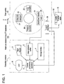
- Figure 1 is a block diagram of the configuration of a multi-row detector X-ray CT apparatus in accordance with a first embodiment of the present invention.
- the multi-row detector X-ray CT apparatus 100 comprises an operation console 1, an imaging table 10, and a scan gantry 20.
- the operation console 1 comprises an input device 2 for accepting inputs by a human operator, a central processing apparatus 3 for executing projection data generating processing and pixel data generating processing in accordance with the present invention, a data collection buffer 5 for collecting projection data acquired at the scan gantry 20, a CRT 6 for displaying a CT image reconstructed from the projection data, and a storage device 7 for storing programs, data, and X-ray CT images.
- the table apparatus 10 comprises a cradle 12 for laying thereon a subject and transporting the subject into/out of a bore (cavity portion) of the scan gantry 20.
- the cradle 12 is driven by a motor incorporated in the table apparatus 10.
- the scan gantry 20 comprises an X-ray tube 21, an X-ray controller 22, a collimator 23, a multi-row detector 24, a DAS (data acquisition system) 25, a rotation controller 26 for rotating the X-ray tube 21 etc. around the body axis of the subject, and a control interface 29 for communicating control signals etc. with the operation console 1 and imaging table 10.
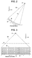
- Figures 2 and 3 are explanatory diagrams of the X-ray tube 21 and the multi-row detector 24.
- the X-ray tube 21 and multi-row detector 24 rotate around a center of rotation IC.
- a vertical direction is represented as a y-direction
- a horizontal direction is represented as an x-direction
- a direction perpendicular to both is represented as a z-direction
- a plane of rotation of the X-ray tube 21 and multi-row detector 24 is an x-y plane.
- the direction of movement of the cradle 12 is the z-direction.
- the X-ray tube 21 generates an X-ray beam generally referred to as a cone beam CB.
- Figure 4 is a flow chart showing image data generating processing in accordance with the first embodiment.
- raw data dj(view, i) represented by a view angle view, detector row index j , and channel index i are collected while rotating the X-ray tube 21 and multi-row detector 24 around the subject to be imaged.
- raw data d1 ⁇ d6 corresponding to a pixel g in a reconstruction field P are obtained as shown in Figure 5.
- the raw data d1 - d6 are obtained from six detector rows that lie closest to a point at which a straight line Lg passing through a focal spot of the X-ray tube 21 and the pixel g in the reconstruction field P intersects the multi-row detector 24.
- the raw data d1 ⁇ d6 are then multiplied by cone-beam reconstruction weights W1 ⁇ W6 and Z-filter weights w1 ⁇ w6 and are added to calculate a projection datum Dg corresponding to the pixel g in the reconstruction field P.
- the cone-beam reconstruction weight W1 is defined as (r1 / r0 ) 2 , where the distance from the focal spot of the X-ray tube 21 to a detector row j , channel i of the multi-row detector 24 that corresponds to the raw data d1 is represented as r0 , and the distance from the focal spot of the X-ray tube 21 to the pixel g in the reconstruction field corresponding to the raw data d1 is represented as r1.
- the cone-beam reconstruction weights W2 ⁇ W6 are similarly defined.
- the Z-filter weights w1 ⁇ w6 are defined by a Z-filter for six-point interpolation known in the art, and are defined by a Z-filter Fz as exemplary shown in Figure 6.
- Step A3 backprojection processing is applied to the projection datum Dg to calculate a pixel datum Gg.
- the raw data d1 ⁇ d6 of six adjacent detector rows are multiplied by the Z-filter weights w1 ⁇ w6 and are added to calculate one projection datum Dg, and backprojection processing is applied to such projection data Dg to calculate pixel data Gg ; therefore, an image having a large slice thickness, such as a thickness twice or three times the size of the detector as measured in the Z-axis direction, can be obtained. Moreover, an image having an arbitrary slice thickness, such as a thickness 1.2 or 2.5 times the size of the detector as measured in the Z-axis direction, can be obtained.
- the process can be similarly applied to a case in which raw data of three or more adjacent detector rows are employed.
- Figure 7 is a flow chart showing image data generating processing in accordance with a second embodiment.
- Step B1 raw data dj(view, ⁇ , i ) represented by a view angle view, relative angular difference ⁇ , detector row index j , and channel index i are collected while rotating the X-ray tube 21 and multi-row detector 24 around the subject to be imaged and linearly moving the cradle 12.
- the cradle 12 is configured to linearly move by an amount corresponding to two detector rows per rotation.
- raw data d11 and d12 corresponding to a pixel g in a reconstruction field P are obtained for a first rotation as shown in Figure 8.
- the raw data d11 and d12 are obtained from two detector rows that lie closest to a point at which a straight line Lg passing through a focal spot of the X-ray tube 21 and the pixel g in the reconstruction field P intersects the multi-row detector 24.
- the raw data d11 and d12 are then multiplied by cone-beam reconstruction weights Wa and Wb and Z-filter weights wa and wb and are added to calculate a projection datum Dg1 corresponding to the pixel g in the reconstruction field P.
- the cone-beam reconstruction weight Wa is defined as ( r1 / r0 ) 2 , where the distance from the focal spot of the X-ray tube 21 to a detector row j , channel i of the multi-row detector 24 that corresponds to the raw data d11 is represented as r0 , and the distance from the focal spot of the X-ray tube 21 to the pixel g in the reconstruction field corresponding to the raw data d11 is represented as r1.
- the cone-beam reconstruction weight Wb is similarly defined.
- raw data d21 and d22 corresponding to the pixel g in the reconstruction field P are obtained for a second rotation as shown in Figure 8.
- the raw data d21 and d22 are obtained from two detector rows that lie closest to a point at which the straight line Lg passing through the focal spot of the X-ray tube 21 and the pixel g in the reconstruction field P intersects the multi-row detector 24.
- the raw data d21 and d22 are then multiplied by cone-beam reconstruction weights Wa and Wb and Z-filter weights wa and wb and are added to calculate a projection datum Dg2 corresponding to the pixel g in the reconstruction field P.
- the cone-beam reconstruction weight Wa is defined as (r1 / r0) 2 , where the distance from the focal spot of the X-ray tube 21 to a detector row j , channel i of the multi-row detector 24 that corresponds to the raw data d21 is represented as r0 , and the distance from the focal spot of the X-ray tube 21 to the pixel g in the reconstruction field corresponding to the raw data d21 is represented as r1.
- the cone-beam reconstruction weight Wb is similarly defined.
- raw data d31 and d32 corresponding to the pixel g in the reconstruction field P are obtained for a third rotation as shown in Figure 8.
- the raw data d31 and d32 are obtained from two detector rows that lie closest to a point at which the straight line Lg passing through the focal spot of the X-ray tube 21 and the pixel g in the reconstruction field P intersects the multi-row detector 24.
- the raw data d31 and d32 are then multiplied by cone-beam reconstruction weights Wa and Wb and Z-filter weights wa and wb and are added to calculate a projection datum Dg3 corresponding to the pixel g in the reconstruction field P.
- the cone-beam reconstruction weight Wa is defined as (r1 / r0 ) 2 , where the distance from the focal spot of the X-ray tube 21 to a detector row j , channel i of the multi-row detector 24 that corresponds to the raw data d31 is represented as r0 , and the distance from the focal spot of the X-ray tube 21 to the pixel g in the reconstruction field corresponding to the raw data d31 is represented as r1.
- the cone-beam reconstruction weight Wb is similarly defined.
- the projection data Dg1 ⁇ Dg3 are multiplied by the Z-filter weights w1 ⁇ w3 and are added to calculate a projection datum Dg corresponding to the pixel g in the reconstruction field P.
- the Z-filter weights w1 ⁇ w3 are defined by a Z-filter for three-point interpolation known in the art.
- Step B6 backprojection processing is applied to the projection datum Dg to calculate a pixel datum Gg.
- an image having a large slice thickness such as a thickness twice or three times the size of the detector as measured in the Z-axis direction
- an image having an arbitrary slice thickness such as a thickness 1.2 or 2.5 times the size of the detector as measured in the Z-axis direction
- a projection datum for each rotation is generated using a Z-filter for two-point interpolation, calculation is simplified.
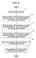
- Figure 9 is a flow chart showing image data generating processing in accordance with a third embodiment.
- raw data dj(view, ⁇ , i) represented by a view angle view, relative angular difference ⁇ , detector row index j , and channel index i are collected while rotating the X-ray tube 21 and multi-row detector 24 around the subject to be imaged and linearly moving the cradle 12.
- the cradle 12 is configured to linearly move by an amount corresponding to three detector rows per rotation.
- raw data d11 ⁇ d13 corresponding to a pixel g in a reconstruction field P are obtained for a first rotation as shown in Figure 10.
- the raw data d11 ⁇ d13 are obtained from three detector rows that lie closest to a point at which a straight line Lg passing through a focal spot of the X-ray tube 21 and the pixel g in the reconstruction field P intersects the multi-row detector 24.
- the raw data d11 ⁇ d13 are then multiplied by cone-beam reconstruction weights W1 ⁇ W3 and Z-filter weights w1 ⁇ w3 and are added to calculate a projection datum Dg1 corresponding to the pixel g in the reconstruction field P.
- the cone-beam reconstruction weight W1 is defined as ( r1 / r0 ) 2 , where the distance from the focal spot of the X-ray tube 21 to a detector row j, channel i of the multi-row detector 24 that corresponds to the raw data d11 is represented as r0 , and the distance from the focal spot of the X-ray tube 21 to the pixel g in the reconstruction field corresponding to the raw data d11 is represented as r1.
- the cone-beam reconstruction weights W2 and W3 are similarly defined.
- the Z-filter weights w1 ⁇ w3 are defined by a Z-filter for three-point interpolation known in the art.
- raw data d21 ⁇ d23 corresponding to the pixel g in the reconstruction field P are obtained for a second rotation as shown in Figure 10.
- the raw data d21 ⁇ d23 are obtained from three detector rows that lie closest to a point at which the straight line Lg passing through the focal spot of the X-ray tube 21 and the pixel g in the reconstruction field P intersects the multi-row detector 24.
- the raw data d21 ⁇ d23 are then multiplied by cone-beam reconstruction weights W1 ⁇ W3 and Z-filter weights w1 ⁇ w3 and are added to calculate a projection datum Dg2 corresponding to the pixel g in the reconstruction field P.
- the cone-beam reconstruction weight W1 is defined as (r1 / r0 ) 2 , where the distance from the focal spot of the X-ray tube 21 to a detector row j, channel i of the multi-row detector 24 that corresponds to the raw data d21 is represented as r0 , and the distance from the focal spot of the X-ray tube 21 to the pixel g in the reconstruction field corresponding to the raw data d21 is represented as r1.
- the cone-beam reconstruction weights W2 and W3 are similarly defined.
- the Z-filter weights w1 ⁇ w3 are defined by a Z-filter for three-point interpolation known in the art.
- raw data d31 ⁇ d33 corresponding to the pixel g in the reconstruction field P are obtained for a third rotation as shown in Figure 10.
- the raw data d31 ⁇ d33 are obtained from three detector rows that lie closest to a point at which the straight line Lg passing through the focal spot of the X-ray tube 21 and the pixel g in the reconstruction field P intersects the multi-row detector 24.
- the raw data d31 ⁇ d33 are then multiplied by cone-beam reconstruction weights W1 ⁇ W3 and Z-filter weights w1 ⁇ w3 and are added to calculate a projection datum Dg3 corresponding to the pixel g in the reconstruction field P.
- the cone-beam reconstruction weight W1 is defined as ( r1 / r0 ) 2 , where the distance from the focal spot of the X-ray tube 21 to a detector row j , channel i of the multi-row detector 24 that corresponds to the raw data d31 is represented as r0 , and the distance from the focal spot of the X-ray tube 21 to the pixel g in the reconstruction field corresponding to the raw data d31 is represented as r1.
- the cone-beam reconstruction weights W2 and W3 are similarly defined.
- the Z-filter weights w1 ⁇ w3 are defined by a Z-filter for three-point interpolation known in the art.
- the projection data Dg1 ⁇ Dg3 are multiplied by Z-filter weights w1' ⁇ w3' and are added to calculate a projection datum Dg corresponding to the pixel g in the reconstruction field P.
- the Z-filter weights w1' ⁇ w3' are defined by a Z-filter for three-point interpolation known in the art.
- Step C6 backprojection processing is applied to the projection datum Dg to calculate a pixel datum Gg.
- an image having a large slice thickness such as a thickness twice or three times the size of the detector as measured in the Z-axis direction
- an image having an arbitrary slice thickness such as a thickness 1.2 or 2.5 times the size of the detector as measured in the Z-axis direction
- the slice thickness corresponding to projection data for each rotation can be made larger than the size of the detector as measured in the Z-axis direction.
- the process can be similarly applied to a case in which raw data of four or more adjacent detector rows are employed.
- the process can be similarly applied to a case in which raw data for two or four or more consecutive rotations are employed.
- Figure 11 is a flow chart showing image data generating processing in accordance with a fourth embodiment.
- raw data dj ( view, i ) represented by a view angle view, detector row index j , and channel index i are collected while rotating the X-ray tube 21 and multi-row detector 24 around the subject to be imaged.
- raw data d1 and d2 corresponding to a pixel g in a first reconstruction field P1 are obtained as shown in Figure 12.
- the raw data d1 and d2 are obtained from two detector rows that lie closest to a point at which a straight line Lg1 passing through a focal spot of the X-ray tube 21 and the pixel g in the first reconstruction field P1 intersects the multi-row detector 24.
- the raw data d1 and d2 are then multiplied by cone-beam reconstruction weights Wa and Wb and Z-filter weights wa and wb and are added to calculate a projection datum Dg1 corresponding to the pixel g in the first reconstruction field P1.
- the cone-beam reconstruction weight Wa is defined as ( r1 / r0 ) 2 , where the distance from the focal spot of the X-ray tube 21 to a detector row j , channel i of the multi-row detector 24 that corresponds to the raw data d1 is represented as r0 , and the distance from the focal spot of the X-ray tube 21 to the pixel g in the reconstruction field corresponding to the raw data d1 is represented as r1.
- the cone-beam reconstruction weight Wb is similarly defined.
- Step E3 backprojection processing is applied to the projection datum Dg1 to calculate a pixel datum Gg1.
- raw data d3 and d4 corresponding to a pixel g in a second reconstruction field P2 are obtained as shown in Figure 12.
- the raw data d3 and d4 are obtained from two detector rows that lie closest to a point at which a straight line Lg2 passing through the focal spot of the X-ray tube 21 and the pixel g in the second reconstruction field P2 intersects the multi-row detector 24.
- the raw data d3 and d4 are then multiplied by cone-beam reconstruction weights Wa and Wb and Z-filter weights wa and wb and are added to calculate a projection datum Dg2 corresponding to the pixel g in the second reconstruction field P2.
- the cone-beam reconstruction weight Wa is defined as (r1 / r0 ) 2 , where the distance from the focal spot of the X-ray tube 21 to a detector row j , channel i of the multi-row detector 24 that corresponds to the raw data d3 is represented as r0 , and the distance from the focal spot of the X-ray tube 21 to the pixel g in the reconstruction field corresponding to the raw data d3 is represented as r1 .
- the cone-beam reconstruction weight Wb is similarly defined.
- Step E5 backprojection processing is applied to the projection datum Dg2 to calculate a pixel datum Gg2.
- raw data d5 and d6 corresponding to a pixel g in a third reconstruction field P3 are obtained as shown in Figure 12.
- the raw data d5 and d6 are obtained from two detector rows that lie closest to a point at which a straight line Lg3 passing through the focal spot of the X-ray tube 21 and the pixel g in the third reconstruction field P3 intersects the multi-row detector 24.
- the raw data d5 and d6 are then multiplied by cone-beam reconstruction weights Wa and Wb and Z-filter weights wa and wb and are added to calculate a projection datum Dg3 corresponding to the pixel g in the third reconstruction field P3.
- the cone-beam reconstruction weight Wa is defined as ( r1 / r0 ) 2 , where the distance from the focal spot of the X-ray tube 21 to a detector row j , channel i of the multi-row detector 24 that corresponds to the raw data d5 is represented as r0 , and the distance from the focal spot of the X-ray tube 21 to the pixel g in the reconstruction field corresponding to the raw data d5 is represented as r1.
- the cone-beam reconstruction weight Wb is similarly defined.
- Step E7 backprojection processing is applied to the projection datum Dg3 to calculate a pixel datum Gg3 .
- Step E8 the pixel data Gg1 ⁇ Gg3 are multiplied by Z-filter weights w1 ⁇ w3 and are added to generate a pixel datum Gg .
- the Z-filter weights w1 ⁇ w3 are defined by a Z-filter for three-point interpolation known in the art.
- an image having a large slice thickness such as a thickness twice or three times the size of the detector as measured in the Z-axis direction
- an image having an arbitrary slice thickness such as a thickness 1.2 or 2.5 times the size of the detector as measured in the Z-axis direction
- images having a small slice thickness can be simultaneously obtained.
- the process can be similarly applied to a case in which two or four or more proximate reconstruction fields are employed.
- the projection datum for each reconstruction field is obtained from raw data of two adjacent detector rows, raw data of three or more adjacent detector rows may be employed.
- a helical scan may be conducted.
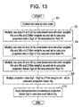
- Figure 13 is a flow chart showing image data generating processing in accordance with a fifth embodiment.
- raw data dj ( view , i) represented by a view angle view, detector row index j , and channel index i are collected while rotating the X-ray tube 21 and multi-row detector 24 around the subject to be imaged.
- raw data d1 and d2 corresponding to a pixel g in a first reconstruction field P1 are obtained as shown in Figure 12.
- the raw data d1 and d2 are obtained from two detector rows that lie closest to a point at which a straight line Lg1 passing through a focal spot of the X-ray tube 21 and the pixel g in the first reconstruction field P1 intersects the multi-row detector 24.
- the raw data d1 and d2 are then multiplied by cone-beam reconstruction weights Wa and Wb and Z-filter weights wa and wb and are added to calculate a projection datum Dg1 corresponding to the pixel g in the first reconstruction field P1.
- the cone-beam reconstruction weight Wa is defined as ( r1 / r0 ) 2 , where the distance from the focal spot of the X-ray tube 21 to a detector row j , channel i of the multi-row detector 24 that corresponds to the raw data d1 is represented as r0 , and the distance from the focal spot of the X-ray tube 21 to the pixel g in the reconstruction field corresponding to the raw data d1 is represented as r1.
- the cone-beam reconstruction weight Wb is similarly defined.
- raw data d3 and d4 corresponding to a pixel g in a second reconstruction field P2 are obtained as shown in Figure 12.
- the raw data d3 and d4 are obtained from two detector rows that lie closest to a point at which a straight line Lg2 passing through the focal spot of the X-ray tube 21 and the pixel g in the second reconstruction field P2 intersects the multi-row detector 24.
- the raw data d3 and d4 are then multiplied by cone-beam reconstruction weights Wa and Wb and Z-filter weights wa and wb and are added to calculate a projection datum Dg2 corresponding to the pixel g in the second reconstruction field P2.
- the cone-beam reconstruction weight Wa is defined as (r1 / r0 ) 2 , where the distance from the focal spot of the X-ray tube 21 to a detector row j , channel i of the multi-row detector 24 that corresponds to the raw data d3 is represented as r0 , and the distance from the focal spot of the X-ray tube 21 to the pixel g in the reconstruction field corresponding to the raw data d3 is represented as r1.
- the cone-beam reconstruction weight Wb is similarly defined.
- raw data d5 and d6 corresponding to a pixel g in a third reconstruction field P3 are obtained as shown in Figure 12.
- the raw data d5 and d6 are obtained from two detector rows that lie closest to a point at which a straight line Lg3 passing through the focal spot of the X-ray tube 21 and the pixel g in the third reconstruction field P3 intersects the multi-row detector 24.
- the raw data d5 and d6 are then multiplied by cone-beam reconstruction weights Wa and Wb and Z-filter weights wa and wb and are added to calculate a projection datum Dg3 corresponding to the pixel g in the third reconstruction field P3.
- the cone-beam reconstruction weight Wa is defined as (r1 / r0 ) 2 , where the distance from the focal spot of the X-ray tube 21 to a detector row j , channel i of the multi-row detector 24 that corresponds to the raw data d5 is represented as r0 , and the distance from the focal spot of the X-ray tube 21 to the pixel g in the reconstruction field corresponding to the raw data d5 is represented as r1.
- the cone-beam reconstruction weight Wb is similarly defined.
- the projection data Dg1 ⁇ Dg3 are multiplied by Z-filter weights w1 ⁇ w3 and are added to calculate a projection datum Dg.
- the Z-filter weights w1 ⁇ w3 are defined by a Z-filter for three-point interpolation known in the art.
- Step E10 backprojection processing is applied to the projection datum Dg to calculate a pixel datum Dg.
- an image having a large slice thickness such as a thickness twice or three times the size of the detector as measured in the Z-axis direction
- an image having an arbitrary slice thickness such as a thickness 1.2 or 2.5 times the size of the detector as measured in the Z-axis direction
- processing is simplified as compared with the fourth embodiment, although images having a small slice thickness cannot be simultaneously obtained.
- the process can be similarly applied to a case in which two or four or more proximate reconstruction fields are employed.
- the projection datum for each reconstruction field is obtained from raw data of two adjacent detector rows, raw data of three or more adjacent detector rows may be employed.
- a helical scan may be conducted.
Landscapes
- Physics & Mathematics (AREA)
- General Physics & Mathematics (AREA)
- Engineering & Computer Science (AREA)
- Theoretical Computer Science (AREA)
- Apparatus For Radiation Diagnosis (AREA)
- Image Processing (AREA)
Abstract
Description
- The present invention relates to a projection data generating method, a pixel data generating method, and a multi-row detector X-ray CT (computed tomography) apparatus, and more particularly to a method of generating projection data for use in producing an image having a large slice thickness, based on raw data collected by an axial scan or helical scan using a multi-row detector, a method of generating pixel data for the image having a large slice thickness, and a multi-row detector X-ray CT apparatus.
- Figure 14 is a flow chart showing pixel data generating processing in a conventional multi-row detector X-ray CT apparatus.
- At Step J1, raw data is collected while rotating an X-ray tube and a multi-row detector around a subject to be imaged.
- At Step J2, raw data d1 and d2 corresponding to a pixel g in a reconstruction field P are obtained as shown in Figure 15. Specifically, the raw data d1 and d2 are obtained from two detector rows that lie closest to a point at which a straight line Lg passing through a focal spot of an
X-ray tube 21 and the pixel g in the reconstruction field P intersects amulti-row detector 24. The raw data d1 and d2 are then multiplied by cone-beam reconstruction weights Wa and Wb and Z-filter weights wa and wb and are added to calculate a projection datum Dg corresponding to the pixel g in the reconstruction field P. - The cone-beam reconstruction weight Wa is defined as (r1 / r0)2, where the distance from the focal spot of the
X-ray tube 21 to a detector row j, channel i of themulti-row detector 24 that corresponds to the raw data d1 is represented as r0, and the distance from the focal spot of theX-ray tube 21 to the pixel g in the reconstruction field corresponding to the raw data d1 is represented as r1. - The cone-beam reconstruction weight Wb is similarly defined.
- The Z-filter weights wa and wb are defined as wa = b / (a + b) and wb = a / (a + b), where the distance between the point at which the straight line Lg intersects the
multi-row detector 24 and a point corresponding to the raw data d1 as measured in the Z-direction of the detector is represented as a, and the distance between the point at which the straight line Lg intersects themulti-row detector 24 and a point corresponding to the raw data d2 as measured in the Z-direction of the detector is represented as b. These are weights as delineated by a Z-filter Fz shown in Figure 16. - Referring again to Figure 14, at Step J3, backprojection processing is applied to the projection datum Dg to calculate a pixel datum Gg.
- An image obtained by the conventional multi-row detector X-ray CT apparatus has a slice thickness approximately equal to the size of the detector as measured in the Z-axis direction.
- There has been a problem that an image cannot be obtained with a large slice thickness, such as a thickness twice or three times the size of the detector as measured in the Z-axis direction.
- It is therefore an object of the present invention to provide a method of generating projection data for use in producing an image having a large slice thickness, based on raw data collected using a multi-row detector, a method of generating pixel data for the image having a large slice thickness, and a multi-row detector X-ray CT apparatus.
- In accordance with its first aspect, the present invention provides a projection data generating method characterized in comprising: multiplying raw data of three or more adjacent detector rows collected using a multi-row detector having three or more detector rows, by cone-beam reconstruction weights and Z-filter weights, and adding the multiplied raw data to obtain one projection datum.
- In the projection data generating method of the first aspect, raw data of three or more adjacent detector rows are multiplied by Z-filter weights and added to generate one projection datum. By then applying backprojection processing to such projection data, an image having a large slice thickness, such as a thickness twice or three times the size of the detector as measured in the Z-axis direction, can be obtained. Moreover, an image having an arbitrary slice thickness, such as a thickness 1.2 or 2.5 times the size of the detector as measured in the Z-axis direction, can be obtained.
- The Z-filter weights are defined by a Z-filter for multi-point interpolation for three or more points known in the art (e.g., Hanning interpolation or cubic interpolation).
- In accordance with its second aspect, the present invention provides a pixel data generating method characterized in comprising: applying backprojection processing to the projection data generated by the projection data generating method having the aforementioned configuration to obtain pixel data.
- In the pixel data generating method of the second aspect, raw data of three or more adjacent detector rows are multiplied by Z-filter weights and added to generate one projection datum, and backprojection processing is applied to such projection data to obtain pixel data; therefore, an image having a large slice thickness, such as a thickness twice or three times the size of the detector as measured in the Z-axis direction, can be obtained. Moreover, an image having an arbitrary slice thickness, such as a thickness 1.2 or 2.5 times the size of the detector as measured in the Z-axis direction, can be obtained.
- In accordance with its third aspect, the present invention provides a projection data generating method characterized in comprising: generating an i-th projection datum corresponding to a pixel in a reconstruction field from raw data of k adjacent detector rows for an i-th rotation among raw data collected by a helical scan in which a multi-row detector having two or more detector rows is employed and k (≥ 2) or more rows go forward per rotation; repeating the generation of the i-th projection datum for i = 1 ― n, n ≥ 2; and multiplying first ― n-th projection data by Z-filter weights and adding the multiplied projection data to obtain one projection datum.
- In the projection data generating method of the third aspect, raw data of k adjacent detector rows are multiplied by Z-filter weights and are added to generate one projection datum for each rotation of a helical scan, and the projection data for the rotations are multiplied by Z-filter weights and added to obtain one projection datum. By then applying backprojection processing to such projection data, an image having a large slice thickness, such as a thickness twice or three times the size of the detector as measured in the Z-axis direction, can be obtained. Moreover, an image having an arbitrary slice thickness, such as a thickness 1.2 or 2.5 times the size of the detector as measured in the Z-axis direction, can be obtained.
- The Z-filter weights are defined by a Z-filter for two-point interpolation or for multi-point interpolation for three or more points known in the art.
- In accordance with its fourth aspect, the present invention provides the projection data generating method having the aforementioned configuration, characterized in that: k = 2, and the i-th projection datum is generated by multiplying raw data of two adjacent detector rows by cone-beam reconstruction weights and Z-filter weights, and adding the multiplied raw data.
- In the projection data generating method of the fourth aspect, a Z-filter for two-point interpolation known in the art can be employed to generate a projection datum for each rotation.
- In accordance with its fifth aspect, the present invention provides the projection data generating method having the aforementioned configuration, characterized in that: k = 3, and the i-th projection datum is generated by multiplying raw data of k adjacent detector rows by cone-beam reconstruction weights and Z-filter weights, and adding the multiplied raw data.
- In the projection data generating method of the fifth aspect, a Z-filter for multi-point interpolation for three or more points known in the art can be employed to generate a projection datum for each rotation.
- In accordance with its sixth aspect, the present invention provides a pixel data generating method characterized in comprising: applying backprojection processing to the projection data generated by the projection data generating method having the aforementioned configuration to obtain pixel data.
- In the pixel data generating method of the sixth aspect, raw data of k adjacent detector rows are multiplied by Z-filter weights and are added to generate one projection datum for each rotation of a helical scan, the projection data for the rotations are multiplied by Z-filter weights and added to obtain one projection datum, and backprojection processing is applied to such projection data to obtain pixel data; therefore, an image having a large slice thickness, such as a thickness twice or three times the size of the detector as measured in the Z-axis direction, can be obtained. Moreover, an image having an arbitrary slice thickness, such as a thickness 1.2 or 2.5 times the size of the detector as measured in the Z-axis direction, can be obtained.
- In accordance with its seventh aspect, the present invention provides a pixel data generating method characterized in comprising: generating an i-th pixel datum corresponding to a pixel in an i-th reconstruction field from raw data of k adjacent detector rows among raw data collected using a multi-row detector having two or more detector rows; repeating the generation of the i-th pixel datum for i = 1 ― n, n ≥ 2; and multiplying first ― n-th pixel data by Z-filter weights and adding the multiplied pixel data to obtain one pixel datum.
- In the pixel data generating method of the seventh aspect, a pixel datum is generated from raw data of k adjacent detector rows for each of first ― n-th reconstruction fields, and the pixel data for the reconstruction fields are multiplied by Z-filter weights and added to obtain one pixel datum; therefore, an image having a large slice thickness, such as a thickness twice or three times the size of the detector as measured in the Z-axis direction, can be obtained. Moreover, an image having an arbitrary slice thickness, such as a thickness 1.2 or 2.5 times the size of the detector as measured in the Z-axis direction, can be obtained. In addition, an image for each reconstruction field can be obtained.
- In accordance with its eighth aspect, the present invention provides the pixel data generating method having the aforementioned configuration, characterized in that: k = 2, and the i-th pixel datum is generated by multiplying raw data of two adjacent detector rows by cone-beam reconstruction weights and Z-filter weights, adding the multiplied raw data to obtain an i-th projection datum, and applying backprojection processing to the i-th projection datum.
- In the pixel data generating method of the eighth aspect, pixel data for each reconstruction field can be obtained using processing quite the same as the conventional technique.
- In accordance with its ninth aspect, the present invention provides a projection data generating method characterized in comprising: generating an i-th projection datum corresponding to a pixel in an i-th reconstruction field from raw data of k (k ≥ 2) adjacent detector rows among raw data collected using a multi-row detector having two or more detector rows; repeating the generation of the i-th projection datum for i = 1 ― n, n ≥ 2; and multiplying first ― n-th projection data by Z-filter weights and adding the multiplied projection data to obtain one projection datum.
- In the projection data generating method of the ninth aspect, a projection datum is generated from raw data of k adjacent detector rows for each of first - n-th reconstruction fields, and the projection data for the reconstruction fields are multiplied by Z-filter weights and added to obtain one projection datum. By then applying backprojection processing to such projection data, an image having a large slice thickness, such as a thickness twice or three times the size of the detector as measured in the Z-axis direction, can be obtained. Moreover, an image having an arbitrary slice thickness, such as a thickness 1.2 or 2.5 times the size of the detector as measured in the Z-axis direction, can be obtained.
- In accordance with its tenth aspect, the present invention provides the projection data generating method having the aforementioned configuration, characterized in that: k = 2, and the i-th projection datum is generated by multiplying raw data of two adjacent detector rows by cone-beam reconstruction weights and Z-filter weights, and adding the multiplied raw data.
- In the projection data generating method of the tenth aspect, projection data for each reconstruction field can be obtained using processing quite the same as the conventional technique.
- In accordance with its eleventh aspect, the present invention provides a pixel data generating method characterized in comprising: applying backprojection processing to the projection data generated by the projection data generating method having the aforementioned configuration to obtain pixel data.
- In the pixel data generating method of the eleventh aspect, a projection datum is generated from raw data of k adjacent detector rows for each of first ― n-th reconstruction fields, the projection data for the reconstruction fields are multiplied by Z-filter weights and added to obtain one projection datum, and backprojection processing is applied to such projection data to obtain pixel data; therefore, an image having a large slice thickness, such as a thickness twice or three times the size of the detector as measured in the Z-axis direction, can be obtained. Moreover, an image having an arbitrary slice thickness, such as a thickness 1.2 or 2.5 times the size of the detector as measured in the Z-axis direction, can be obtained.
- In accordance with its twelfth aspect, the present invention provides a multi-row detector X-ray CT apparatus characterized in comprising: an X-ray tube; a multi-row detector having three or more detector rows; scanning means for collecting raw data while rotating at least one of said X-ray tube and said multi-row detector around a subject to be imaged or while rotating at least one of them and at the same time linearly moving both of them relative to the subject to be imaged; projection data generating means for multiplying raw data of three or more adjacent detector rows by cone-beam reconstruction weights and Z-filter weights, and adding the multiplied raw data to obtain one projection datum; and backprojection processing means for applying backprojection processing to the projection data to obtain pixel data.
- In the multi-row detector X-ray CT apparatus of the twelfth aspect, the projection data generating method of the first aspect and the pixel data generating method of the second aspect can be suitably implemented.
- In accordance with its thirteenth aspect, the present invention provides a multi-row detector X-ray CT apparatus characterized in comprising: an X-ray tube; a multi-row detector having two or more detector rows; scanning means for collecting raw data while rotating at least one of said X-ray tube and said multi-row detector around a subject to be imaged or while rotating at least one of them and at the same time linearly moving both of them relative to the subject to be imaged; projection data generating means for generating an i-th projection datum corresponding to a pixel in a reconstruction field from raw data of k adjacent detector rows for an i-th rotation among raw data collected by a helical scan in which k (≥ 2) or more rows go forward per rotation, repeating the generation of the i-th projection datum for i = 1 ― n, n ≥ 2, and next multiplying first ― n-th projection data by Z-filter weights and adding the multiplied projection data to obtain one projection datum; and backprojection processing means for applying backprojection processing to the projection data to obtain pixel data.
- In the multi-row detector X-ray CT apparatus of the thirteenth aspect, the projection data generating method of the third ― fifth aspects and the pixel data generating method of the sixth aspect can be suitably implemented.
- In accordance with its fourteenth aspect, the present invention provides the multi-row detector X-ray CT apparatus having the aforementioned configuration, characterized in that: k = 2, and said projection data generating means generates the i-th projection datum by multiplying raw data of two adjacent detector rows by cone-beam reconstruction weights and Z-filter weights, and adding the multiplied raw data.
- In the multi-row detector X-ray CT apparatus of the fourteenth aspect, the projection data generating method of the fourth aspect can be suitably implemented.
- In accordance with its fifteenth aspect, the present invention provides a multi-row detector X-ray CT apparatus characterized in comprising: an X-ray tube; a multi-row detector having two or more detector rows; scanning means for collecting raw data while rotating at least one of said X-ray tube and said multi-row detector around a subject to be imaged or while rotating at least one of them and at the same time linearly moving both of them relative to the subject to be imaged; pixel data generating means for generating an i-th pixel datum corresponding to a pixel in an i-th reconstruction field from raw data of k (k ≥ 2) adjacent detector rows among the raw data, repeating the generation of the i-th pixel datum for i = 1 ― n, n ≥ 2, and next multiplying first ― n-th pixel data by Z-filter weights and adding the multiplied pixel data to obtain one pixel datum.
- In the multi-row detector X-ray CT apparatus of the fifteenth aspect, the pixel data generating method of the seventh and eighth aspects can be suitably implemented.
- In accordance with its sixteenth aspect, the present invention provides a multi-row detector X-ray CT apparatus characterized in comprising: an X-ray tube; a multi-row detector having two or more detector rows; scanning means for collecting raw data while rotating at least one of said X-ray tube and said multi-row detector around a subject to be imaged or while rotating at least one of them and at the same time linearly moving both of them relative to the subject to be imaged; projection data generating means for generating an i-th projection datum corresponding to a pixel in an i-th reconstruction field from raw data of k (k ≥ 2) adjacent detector rows among the raw data, repeating the generation of the i-th projection datum for i = 1 ― n, n ≥ 2, and then multiplying first ― n-th projection data by Z-filter weights and adding the multiplied projection data to obtain one projection datum; and backprojection processing means for applying backprojection processing to the projection data to obtain pixel data.
- In the multi-row detector X-ray CT apparatus of the sixteenth aspect, the projection data generating method of the ninth and tenth aspects and the pixel data generating method of the eleventh aspect can be suitably implemented.
- According to the projection data generating method, pixel data generating method, and multi-row detector X-ray CT apparatus of the present invention, an image having a large slice thickness, such as a thickness twice or three times the size of the detector as measured in the Z-axis direction, can be obtained based on raw data collected by an axial scan or helical scan using a multi-row detector. Moreover, an image having an arbitrary slice thickness, such as a thickness 1.2 or 2.5 times the size of the detector as measured in the Z-axis direction, can be obtained.
- Further objects and advantages of the present invention will be apparent from the following description of the preferred embodiments of the invention as illustrated in the accompanying drawings, in which:
- Figure 1 is a block diagram showing a multi-row detector X-ray CT apparatus in accordance with the present invention.
- Figure 2 is an explanatory diagram showing a rotation of an X-ray tube and a multi-row detector.
- Figure 3 is an explanatory diagram showing a cone beam.
- Figure 4 is a flow chart showing pixel data generating processing in accordance with a first embodiment.
- Figure 5 is a conceptual diagram showing raw data corresponding to a reconstruction field in the first embodiment.
- Figure 6 is a conceptual diagram showing a Z-filter in the first embodiment.
- Figure 7 is a flow chart showing pixel data generating processing in accordance with a second embodiment.
- Figure 8 is a conceptual diagram showing raw data corresponding to a reconstruction field in the second embodiment.
- Figure 9 is a flow chart showing pixel data generating processing in accordance with a third embodiment.
- Figure 10 is a conceptual diagram showing raw data corresponding to a reconstruction field in the third embodiment.
- Figure 11 is a flow chart showing pixel data generating processing in accordance with a fourth embodiment.
- Figure 12 is a conceptual diagram showing raw data corresponding to reconstruction fields in the fourth embodiment.
- Figure 13 is a flow chart showing pixel data generating processing in accordance with a fifth embodiment.
- Figure 14 is a flow chart showing conventional pixel data generating processing.
- Figure 15 is a conceptual diagram showing raw data corresponding to a conventional reconstruction field.
- Figure 16 is a conceptual diagram showing a conventional Z-filter.
-
- The present invention will now be described in more detail with reference to embodiments shown in the accompanying drawings.
- Figure 1 is a block diagram of the configuration of a multi-row detector X-ray CT apparatus in accordance with a first embodiment of the present invention.
- The multi-row detector X-ray CT apparatus 100 comprises an
operation console 1, an imaging table 10, and ascan gantry 20. - The
operation console 1 comprises aninput device 2 for accepting inputs by a human operator, a central processing apparatus 3 for executing projection data generating processing and pixel data generating processing in accordance with the present invention, adata collection buffer 5 for collecting projection data acquired at thescan gantry 20, aCRT 6 for displaying a CT image reconstructed from the projection data, and astorage device 7 for storing programs, data, and X-ray CT images. - The
table apparatus 10 comprises acradle 12 for laying thereon a subject and transporting the subject into/out of a bore (cavity portion) of thescan gantry 20. Thecradle 12 is driven by a motor incorporated in thetable apparatus 10. - The
scan gantry 20 comprises anX-ray tube 21, anX-ray controller 22, acollimator 23, amulti-row detector 24, a DAS (data acquisition system) 25, arotation controller 26 for rotating theX-ray tube 21 etc. around the body axis of the subject, and acontrol interface 29 for communicating control signals etc. with theoperation console 1 and imaging table 10. - Figures 2 and 3 are explanatory diagrams of the
X-ray tube 21 and themulti-row detector 24. - The
X-ray tube 21 andmulti-row detector 24 rotate around a center of rotation IC. When a vertical direction is represented as a y-direction, a horizontal direction is represented as an x-direction, and a direction perpendicular to both is represented as a z-direction, a plane of rotation of theX-ray tube 21 andmulti-row detector 24 is an x-y plane. The direction of movement of thecradle 12 is the z-direction. - The
X-ray tube 21 generates an X-ray beam generally referred to as a cone beam CB. - The
multi-row detector 24 has, for example, 256 detector rows (J = 256). Each detector row has, for example, 1,024 channels (I = 1,024). - Figure 4 is a flow chart showing image data generating processing in accordance with the first embodiment.
- At Step A1, raw data dj(view, i) represented by a view angle view, detector row index j, and channel index i are collected while rotating the
X-ray tube 21 andmulti-row detector 24 around the subject to be imaged. - At Step A2, raw data d1 ― d6 corresponding to a pixel g in a reconstruction field P are obtained as shown in Figure 5. Specifically, the raw data d1 - d6 are obtained from six detector rows that lie closest to a point at which a straight line Lg passing through a focal spot of the
X-ray tube 21 and the pixel g in the reconstruction field P intersects themulti-row detector 24. The raw data d1 ― d6 are then multiplied by cone-beam reconstruction weights W1 ― W6 and Z-filter weights w1 ― w6 and are added to calculate a projection datum Dg corresponding to the pixel g in the reconstruction field P. - The cone-beam reconstruction weight W1 is defined as (r1 / r0)2, where the distance from the focal spot of the
X-ray tube 21 to a detector row j, channel i of themulti-row detector 24 that corresponds to the raw data d1 is represented as r0, and the distance from the focal spot of theX-ray tube 21 to the pixel g in the reconstruction field corresponding to the raw data d1 is represented as r1. - The cone-beam reconstruction weights W2 ― W6 are similarly defined.
- The Z-filter weights w1 ― w6 are defined by a Z-filter for six-point interpolation known in the art, and are defined by a Z-filter Fz as exemplary shown in Figure 6.
- Referring again to Figure 4, at Step A3, backprojection processing is applied to the projection datum Dg to calculate a pixel datum Gg.
- According to the multi-row detector X-ray CT apparatus 100 of the first embodiment, the raw data d1 ― d6 of six adjacent detector rows are multiplied by the Z-filter weights w1 ― w6 and are added to calculate one projection datum Dg, and backprojection processing is applied to such projection data Dg to calculate pixel data Gg; therefore, an image having a large slice thickness, such as a thickness twice or three times the size of the detector as measured in the Z-axis direction, can be obtained. Moreover, an image having an arbitrary slice thickness, such as a thickness 1.2 or 2.5 times the size of the detector as measured in the Z-axis direction, can be obtained.
- Although the raw data d1 ― d6 of six adjacent detector rows are employed in this embodiment, the process can be similarly applied to a case in which raw data of three or more adjacent detector rows are employed.
- Figure 7 is a flow chart showing image data generating processing in accordance with a second embodiment.
- At Step B1, raw data dj(view, δ, i) represented by a view angle view, relative angular difference δ, detector row index j, and channel index i are collected while rotating the
X-ray tube 21 andmulti-row detector 24 around the subject to be imaged and linearly moving thecradle 12. - The relative angular difference δ is a parameter indicating the number of rotations at the same view angle, and for example, is represented as δ=0° for a first rotation, δ=360° for a second rotation, δ= 720° for a third rotation, and so forth.
- The
cradle 12 is configured to linearly move by an amount corresponding to two detector rows per rotation. - At Step B2, raw data d11 and d12 corresponding to a pixel g in a reconstruction field P are obtained for a first rotation as shown in Figure 8. Specifically, the raw data d11 and d12 are obtained from two detector rows that lie closest to a point at which a straight line Lg passing through a focal spot of the
X-ray tube 21 and the pixel g in the reconstruction field P intersects themulti-row detector 24. The raw data d11 and d12 are then multiplied by cone-beam reconstruction weights Wa and Wb and Z-filter weights wa and wb and are added to calculate a projection datum Dg1 corresponding to the pixel g in the reconstruction field P. - The cone-beam reconstruction weight Wa is defined as (r1 / r0)2, where the distance from the focal spot of the
X-ray tube 21 to a detector row j, channel i of themulti-row detector 24 that corresponds to the raw data d11 is represented as r0, and the distance from the focal spot of theX-ray tube 21 to the pixel g in the reconstruction field corresponding to the raw data d11 is represented as r1. - The cone-beam reconstruction weight Wb is similarly defined.
- The Z-filter weights wa and wb are defined as wa = b / (a + b) and wb = a / (a + b), where the distance between the point at which the straight line Lg intersects the
multi-row detector 24 and a point corresponding to the raw data d11 as measured in the Z-direction of the detector is represented as a, and the distance between the point at which the straight line Lg intersects themulti-row detector 24 and a point corresponding to the raw data d12 as measured in the Z-direction of the detector is represented as b. These are weights as delineated by the Z-filter Fz shown in Figure 16. - Referring again to Figure 7, at Step B3, raw data d21 and d22 corresponding to the pixel g in the reconstruction field P are obtained for a second rotation as shown in Figure 8. Specifically, the raw data d21 and d22 are obtained from two detector rows that lie closest to a point at which the straight line Lg passing through the focal spot of the
X-ray tube 21 and the pixel g in the reconstruction field P intersects themulti-row detector 24. The raw data d21 and d22 are then multiplied by cone-beam reconstruction weights Wa and Wb and Z-filter weights wa and wb and are added to calculate a projection datum Dg2 corresponding to the pixel g in the reconstruction field P. - The cone-beam reconstruction weight Wa is defined as (r1 / r0)2, where the distance from the focal spot of the
X-ray tube 21 to a detector row j, channel i of themulti-row detector 24 that corresponds to the raw data d21 is represented as r0, and the distance from the focal spot of theX-ray tube 21 to the pixel g in the reconstruction field corresponding to the raw data d21 is represented as r1. - The cone-beam reconstruction weight Wb is similarly defined.
- The Z-filter weights wa and wb are defined as wa = b / (a + b) and wb = a / (a + b), where the distance between the point at which the straight line Lg intersects the
multi-row detector 24 and a point corresponding to the raw data d21 as measured in the Z-direction of the detector is represented as a, and the distance between the point at which the straight line Lg intersects themulti-row detector 24 and a point corresponding to the raw data d22 as measured in the Z-direction of the detector is represented as b. These are weights as delineated by the Z-filter Fz shown in Figure 16. - Referring again to Figure 7, at Step B4, raw data d31 and d32 corresponding to the pixel g in the reconstruction field P are obtained for a third rotation as shown in Figure 8. Specifically, the raw data d31 and d32 are obtained from two detector rows that lie closest to a point at which the straight line Lg passing through the focal spot of the
X-ray tube 21 and the pixel g in the reconstruction field P intersects themulti-row detector 24. The raw data d31 and d32 are then multiplied by cone-beam reconstruction weights Wa and Wb and Z-filter weights wa and wb and are added to calculate a projection datum Dg3 corresponding to the pixel g in the reconstruction field P. - The cone-beam reconstruction weight Wa is defined as (r1 / r0)2, where the distance from the focal spot of the
X-ray tube 21 to a detector row j, channel i of themulti-row detector 24 that corresponds to the raw data d31 is represented as r0, and the distance from the focal spot of theX-ray tube 21 to the pixel g in the reconstruction field corresponding to the raw data d31 is represented as r1. - The cone-beam reconstruction weight Wb is similarly defined.
- The Z-filter weights wa and wb are defined as wa = b / (a + b) and wb = a / (a + b), where the distance between the point at which the straight line Lg intersects the
multi-row detector 24 and a point corresponding to the raw data d31 as measured in the Z-direction of the detector is represented as a, and the distance between the point at which the straight line Lg intersects themulti-row detector 24 and a point corresponding to the raw data d32 as measured in the Z-direction of the detector is represented as b. These are weights as delineated by the Z-filter Fz shown in Figure 16. - Referring again to Figure 7, at Step B5, the projection data Dg1 ― Dg3 are multiplied by the Z-filter weights w1 ― w3 and are added to calculate a projection datum Dg corresponding to the pixel g in the reconstruction field P.
- The Z-filter weights w1 ― w3 are defined by a Z-filter for three-point interpolation known in the art. When the Z-filter is of the simple addition type, w1 = w2 = w3.
- At Step B6, backprojection processing is applied to the projection datum Dg to calculate a pixel datum Gg.
- According to the multi-row detector X-ray CT apparatus of the second embodiment, an image having a large slice thickness, such as a thickness twice or three times the size of the detector as measured in the Z-axis direction, can be obtained. Moreover, an image having an arbitrary slice thickness, such as a thickness 1.2 or 2.5 times the size of the detector as measured in the Z-axis direction, can be obtained. Furthermore, since a projection datum for each rotation is generated using a Z-filter for two-point interpolation, calculation is simplified.
- Although raw data for three rotations are employed in this embodiment, the process can be similarly applied to a case in which raw data for two or four or more consecutive rotations are employed.
- Figure 9 is a flow chart showing image data generating processing in accordance with a third embodiment.
- At Step C1, raw data dj(view, δ, i) represented by a view angle view, relative angular difference δ, detector row index j, and channel index i are collected while rotating the
X-ray tube 21 andmulti-row detector 24 around the subject to be imaged and linearly moving thecradle 12. - The relative angular difference δ is a parameter indicating the number of rotations at the same view angle, and for example, is represented as δ=0° for a first rotation, δ=360° for a second rotation, δ=720° for a third rotation, and so forth.
- The
cradle 12 is configured to linearly move by an amount corresponding to three detector rows per rotation. - At Step C2, raw data d11 ― d13 corresponding to a pixel g in a reconstruction field P are obtained for a first rotation as shown in Figure 10. Specifically, the raw data d11 ― d13 are obtained from three detector rows that lie closest to a point at which a straight line Lg passing through a focal spot of the
X-ray tube 21 and the pixel g in the reconstruction field P intersects themulti-row detector 24. The raw data d11 ― d13 are then multiplied by cone-beam reconstruction weights W1 ― W3 and Z-filter weights w1 ― w3 and are added to calculate a projection datum Dg1 corresponding to the pixel g in the reconstruction field P. - The cone-beam reconstruction weight W1 is defined as (r1 / r0)2, where the distance from the focal spot of the
X-ray tube 21 to a detector row j, channel i of themulti-row detector 24 that corresponds to the raw data d11 is represented as r0, and the distance from the focal spot of theX-ray tube 21 to the pixel g in the reconstruction field corresponding to the raw data d11 is represented as r1. - The cone-beam reconstruction weights W2 and W3 are similarly defined.
- The Z-filter weights w1 ― w3 are defined by a Z-filter for three-point interpolation known in the art.
- Referring again to Figure 9, at Step C3, raw data d21 ― d23 corresponding to the pixel g in the reconstruction field P are obtained for a second rotation as shown in Figure 10. Specifically, the raw data d21 ― d23 are obtained from three detector rows that lie closest to a point at which the straight line Lg passing through the focal spot of the
X-ray tube 21 and the pixel g in the reconstruction field P intersects themulti-row detector 24. The raw data d21 ― d23 are then multiplied by cone-beam reconstruction weights W1 ― W3 and Z-filter weights w1 ― w3 and are added to calculate a projection datum Dg2 corresponding to the pixel g in the reconstruction field P. - The cone-beam reconstruction weight W1 is defined as (r1 / r0)2, where the distance from the focal spot of the
X-ray tube 21 to a detector row j, channel i of themulti-row detector 24 that corresponds to the raw data d21 is represented as r0, and the distance from the focal spot of theX-ray tube 21 to the pixel g in the reconstruction field corresponding to the raw data d21 is represented as r1. - The cone-beam reconstruction weights W2 and W3 are similarly defined.
- The Z-filter weights w1 ― w3 are defined by a Z-filter for three-point interpolation known in the art.
- Referring again to Figure 9, at Step C4, raw data d31 ― d33 corresponding to the pixel g in the reconstruction field P are obtained for a third rotation as shown in Figure 10. Specifically, the raw data d31 ― d33 are obtained from three detector rows that lie closest to a point at which the straight line Lg passing through the focal spot of the
X-ray tube 21 and the pixel g in the reconstruction field P intersects themulti-row detector 24. The raw data d31 ― d33 are then multiplied by cone-beam reconstruction weights W1 ― W3 and Z-filter weights w1 ― w3 and are added to calculate a projection datum Dg3 corresponding to the pixel g in the reconstruction field P. - The cone-beam reconstruction weight W1 is defined as (r1 / r0)2, where the distance from the focal spot of the
X-ray tube 21 to a detector row j, channel i of themulti-row detector 24 that corresponds to the raw data d31 is represented as r0, and the distance from the focal spot of theX-ray tube 21 to the pixel g in the reconstruction field corresponding to the raw data d31 is represented as r1. - The cone-beam reconstruction weights W2 and W3 are similarly defined.
- The Z-filter weights w1 ― w3 are defined by a Z-filter for three-point interpolation known in the art.
- Referring again to Figure 9, at Step C5, the projection data Dg1 ― Dg3 are multiplied by Z-filter weights w1' ― w3' and are added to calculate a projection datum Dg corresponding to the pixel g in the reconstruction field P.
- The Z-filter weights w1' ― w3' are defined by a Z-filter for three-point interpolation known in the art. When the Z-filter is of the simple addition type, w1'= w2'= w3'.
- At Step C6, backprojection processing is applied to the projection datum Dg to calculate a pixel datum Gg.
- According to the multi-row detector X-ray CT apparatus of the third embodiment, an image having a large slice thickness, such as a thickness twice or three times the size of the detector as measured in the Z-axis direction, can be obtained. Moreover, an image having an arbitrary slice thickness, such as a thickness 1.2 or 2.5 times the size of the detector as measured in the Z-axis direction, can be obtained. Furthermore, the slice thickness corresponding to projection data for each rotation can be made larger than the size of the detector as measured in the Z-axis direction.
- Although the raw data of three adjacent detector rows are employed in this embodiment, the process can be similarly applied to a case in which raw data of four or more adjacent detector rows are employed. Moreover, although raw data for three rotations are employed in this embodiment, the process can be similarly applied to a case in which raw data for two or four or more consecutive rotations are employed.
- Figure 11 is a flow chart showing image data generating processing in accordance with a fourth embodiment.
- At Step E1, raw data dj(view, i) represented by a view angle view, detector row index j, and channel index i are collected while rotating the
X-ray tube 21 andmulti-row detector 24 around the subject to be imaged. - At Step E2, raw data d1 and d2 corresponding to a pixel g in a first reconstruction field P1 are obtained as shown in Figure 12. Specifically, the raw data d1 and d2 are obtained from two detector rows that lie closest to a point at which a straight line Lg1 passing through a focal spot of the
X-ray tube 21 and the pixel g in the first reconstruction field P1 intersects themulti-row detector 24. The raw data d1 and d2 are then multiplied by cone-beam reconstruction weights Wa and Wb and Z-filter weights wa and wb and are added to calculate a projection datum Dg1 corresponding to the pixel g in the first reconstruction field P1. - The cone-beam reconstruction weight Wa is defined as (r1 / r0)2, where the distance from the focal spot of the
X-ray tube 21 to a detector row j, channel i of themulti-row detector 24 that corresponds to the raw data d1 is represented as r0, and the distance from the focal spot of theX-ray tube 21 to the pixel g in the reconstruction field corresponding to the raw data d1 is represented as r1. - The cone-beam reconstruction weight Wb is similarly defined.
- The Z-filter weights wa and wb are defined as wa = b / (a + b) and wb = a / (a + b), where the distance between the point at which the straight line Lg1 intersects the
multi-row detector 24 and a point corresponding to the raw data d1 as measured in the Z-direction of the detector is represented as a, and the distance between the point at which the straight line Lg1 intersects themulti-row detector 24 and a point corresponding to the raw data d2 as measured in the Z-direction of the detector is represented as b. These are weights as delineated by the Z-filter Fz shown in Figure 16. - Referring again to Figure 11, at Step E3, backprojection processing is applied to the projection datum Dg1 to calculate a pixel datum Gg1.
- At Step E4, raw data d3 and d4 corresponding to a pixel g in a second reconstruction field P2 are obtained as shown in Figure 12. Specifically, the raw data d3 and d4 are obtained from two detector rows that lie closest to a point at which a straight line Lg2 passing through the focal spot of the
X-ray tube 21 and the pixel g in the second reconstruction field P2 intersects themulti-row detector 24. The raw data d3 and d4 are then multiplied by cone-beam reconstruction weights Wa and Wb and Z-filter weights wa and wb and are added to calculate a projection datum Dg2 corresponding to the pixel g in the second reconstruction field P2. - The cone-beam reconstruction weight Wa is defined as (r1 / r0)2, where the distance from the focal spot of the
X-ray tube 21 to a detector row j, channel i of themulti-row detector 24 that corresponds to the raw data d3 is represented as r0, and the distance from the focal spot of theX-ray tube 21 to the pixel g in the reconstruction field corresponding to the raw data d3 is represented as r1. - The cone-beam reconstruction weight Wb is similarly defined.
- The Z-filter weights wa and wb are defined as wa = b / (a + b) and wb = a / (a + b), where the distance between the point at which the straight line Lg2 intersects the
multi-row detector 24 and a point corresponding to the raw data d3 as measured in the Z-direction of the detector is represented as a, and the distance between the point at which the straight line Lg2 intersects themulti-row detector 24 and a point corresponding to the raw data d4 as measured in the Z-direction of the detector is represented as b. These are weights as delineated by the Z-filter Fz shown in Figure 16. - Referring again to Figure 11, at Step E5, backprojection processing is applied to the projection datum Dg2 to calculate a pixel datum Gg2.
- At Step E6, raw data d5 and d6 corresponding to a pixel g in a third reconstruction field P3 are obtained as shown in Figure 12. Specifically, the raw data d5 and d6 are obtained from two detector rows that lie closest to a point at which a straight line Lg3 passing through the focal spot of the
X-ray tube 21 and the pixel g in the third reconstruction field P3 intersects themulti-row detector 24. The raw data d5 and d6 are then multiplied by cone-beam reconstruction weights Wa and Wb and Z-filter weights wa and wb and are added to calculate a projection datum Dg3 corresponding to the pixel g in the third reconstruction field P3. - The cone-beam reconstruction weight Wa is defined as (r1 / r0)2, where the distance from the focal spot of the
X-ray tube 21 to a detector row j, channel i of themulti-row detector 24 that corresponds to the raw data d5 is represented as r0, and the distance from the focal spot of theX-ray tube 21 to the pixel g in the reconstruction field corresponding to the raw data d5 is represented as r1. - The cone-beam reconstruction weight Wb is similarly defined.
- The Z-filter weights wa and wb are defined as wa = b / (a + b) and wb = a / (a + b), where the distance between the point at which the straight line Lg3 intersects the
multi-row detector 24 and a point corresponding to the raw data d5 as measured in the Z-direction of the detector is represented as a, and the distance between the point at which the straight line Lg3 intersects themulti-row detector 24 and a point corresponding to the raw data d6 as measured in the Z-direction of the detector is represented as b. These are weights as delineated by the Z-filter Fz shown in Figure 16. - Referring again to Figure 11, at Step E7, backprojection processing is applied to the projection datum Dg3 to calculate a pixel datum Gg3.
- At Step E8, the pixel data Gg1 ― Gg3 are multiplied by Z-filter weights w1 ― w3 and are added to generate a pixel datum Gg.
- The Z-filter weights w1 ― w3 are defined by a Z-filter for three-point interpolation known in the art. When the Z-filter is of the simple addition type, w1 = w2 = w3.
- According to the multi-row detector X-ray CT apparatus of the fourth embodiment, an image having a large slice thickness, such as a thickness twice or three times the size of the detector as measured in the Z-axis direction, can be obtained. Moreover, an image having an arbitrary slice thickness, such as a thickness 1.2 or 2.5 times the size of the detector as measured in the Z-axis direction, can be obtained. Furthermore, images having a small slice thickness can be simultaneously obtained.
- Although the three reconstruction fields P1 ― P3 are employed in this embodiment, the process can be similarly applied to a case in which two or four or more proximate reconstruction fields are employed.
- Moreover, although the projection datum for each reconstruction field is obtained from raw data of two adjacent detector rows, raw data of three or more adjacent detector rows may be employed.
- Furthermore, although the axial scan is conducted, a helical scan may be conducted.
- Figure 13 is a flow chart showing image data generating processing in accordance with a fifth embodiment.
- At Step E1, raw data dj(view, i) represented by a view angle view, detector row index j, and channel index i are collected while rotating the
X-ray tube 21 andmulti-row detector 24 around the subject to be imaged. - At Step E2, raw data d1 and d2 corresponding to a pixel g in a first reconstruction field P1 are obtained as shown in Figure 12. Specifically, the raw data d1 and d2 are obtained from two detector rows that lie closest to a point at which a straight line Lg1 passing through a focal spot of the
X-ray tube 21 and the pixel g in the first reconstruction field P1 intersects themulti-row detector 24. The raw data d1 and d2 are then multiplied by cone-beam reconstruction weights Wa and Wb and Z-filter weights wa and wb and are added to calculate a projection datum Dg1 corresponding to the pixel g in the first reconstruction field P1. - The cone-beam reconstruction weight Wa is defined as (r1 / r0)2, where the distance from the focal spot of the
X-ray tube 21 to a detector row j, channel i of themulti-row detector 24 that corresponds to the raw data d1 is represented as r0, and the distance from the focal spot of theX-ray tube 21 to the pixel g in the reconstruction field corresponding to the raw data d1 is represented as r1. - The cone-beam reconstruction weight Wb is similarly defined.
- The Z-filter weights wa and wb are defined as wa = b / (a + b) and wb = a / (a + b), where the distance between the point at which the straight line Lg1 intersects the
multi-row detector 24 and a point corresponding to the raw data d1 as measured in the Z-direction of the detector is represented as a, and the distance between the point at which the straight line Lg1 intersects themulti-row detector 24 and a point corresponding to the raw data d2 as measured in the Z-direction of the detector is represented as b. These are weights as delineated by the Z-filter Fz shown in Figure 16. - Referring again to Figure 13, at Step E4, raw data d3 and d4 corresponding to a pixel g in a second reconstruction field P2 are obtained as shown in Figure 12. Specifically, the raw data d3 and d4 are obtained from two detector rows that lie closest to a point at which a straight line Lg2 passing through the focal spot of the
X-ray tube 21 and the pixel g in the second reconstruction field P2 intersects themulti-row detector 24. The raw data d3 and d4 are then multiplied by cone-beam reconstruction weights Wa and Wb and Z-filter weights wa and wb and are added to calculate a projection datum Dg2 corresponding to the pixel g in the second reconstruction field P2. - The cone-beam reconstruction weight Wa is defined as (r1 / r0)2, where the distance from the focal spot of the
X-ray tube 21 to a detector row j, channel i of themulti-row detector 24 that corresponds to the raw data d3 is represented as r0, and the distance from the focal spot of theX-ray tube 21 to the pixel g in the reconstruction field corresponding to the raw data d3 is represented as r1. - The cone-beam reconstruction weight Wb is similarly defined.
- The Z-filter weights wa and wb are defined as wa = b / (a + b) and wb = a / (a + b), where the distance between the point at which the straight line Lg2 intersects the
multi-row detector 24 and a point corresponding to the raw data d3 as measured in the Z-direction of the detector is represented as a, and the distance between the point at which the straight line Lg2 intersects themulti-row detector 24 and a point corresponding to the raw data d4 as measured in the Z-direction of the detector is represented as b. These are weights as delineated by the Z-filter Fz shown in Figure 16. - Referring again to Figure 13, at Step E6, raw data d5 and d6 corresponding to a pixel g in a third reconstruction field P3 are obtained as shown in Figure 12. Specifically, the raw data d5 and d6 are obtained from two detector rows that lie closest to a point at which a straight line Lg3 passing through the focal spot of the
X-ray tube 21 and the pixel g in the third reconstruction field P3 intersects themulti-row detector 24. The raw data d5 and d6 are then multiplied by cone-beam reconstruction weights Wa and Wb and Z-filter weights wa and wb and are added to calculate a projection datum Dg3 corresponding to the pixel g in the third reconstruction field P3. - The cone-beam reconstruction weight Wa is defined as (r1 / r0)2, where the distance from the focal spot of the
X-ray tube 21 to a detector row j, channel i of themulti-row detector 24 that corresponds to the raw data d5 is represented as r0, and the distance from the focal spot of theX-ray tube 21 to the pixel g in the reconstruction field corresponding to the raw data d5 is represented as r1. - The cone-beam reconstruction weight Wb is similarly defined.
- The Z-filter weights wa and wb are defined as wa = b / (a + b) and wb = a / (a + b), where the distance between the point at which the straight line Lg3 intersects the
multi-row detector 24 and a point corresponding to the raw data d5 as measured in the Z-direction of the detector is represented as a, and the distance between the point at which the straight line Lg3 intersects themulti-row detector 24 and a point corresponding to the raw data d6 as measured in the Z-direction of the detector is represented as b. These are weights as delineated by the Z-filter Fz shown in Figure 16. - Referring again to Figure 13, at Step E9, the projection data Dg1 ― Dg3 are multiplied by Z-filter weights w1 ― w3 and are added to calculate a projection datum Dg.
- The Z-filter weights w1 ― w3 are defined by a Z-filter for three-point interpolation known in the art. When the Z-filter is of the simple addition type, w1 = w2 = w3.
- At Step E10, backprojection processing is applied to the projection datum Dg to calculate a pixel datum Dg.
- According to the multi-row detector X-ray CT apparatus of the fifth embodiment, an image having a large slice thickness, such as a thickness twice or three times the size of the detector as measured in the Z-axis direction, can be obtained. Moreover, an image having an arbitrary slice thickness, such as a thickness 1.2 or 2.5 times the size of the detector as measured in the Z-axis direction, can be obtained. Moreover, processing is simplified as compared with the fourth embodiment, although images having a small slice thickness cannot be simultaneously obtained.
- Although the three reconstruction fields P1 ― P3 are employed in this embodiment, the process can be similarly applied to a case in which two or four or more proximate reconstruction fields are employed.
- Moreover, although the projection datum for each reconstruction field is obtained from raw data of two adjacent detector rows, raw data of three or more adjacent detector rows may be employed.
- Furthermore, although the axial scan is conducted, a helical scan may be conducted.
- The aforementioned embodiments may be appropriately combined.
Claims (4)
- A multi-row detector X-ray CT apparatus comprising:an X-ray tube;a multi-row detector having three or more detector rows;a scanning device for collecting raw data while rotating at least one of said X-ray tube and said multi-row detector around a subject to be imaged or while rotating at least one of them and at the same time linearly moving both of them relative to the subject to be imaged;a projection data generating device for multiplying raw data of three or more adjacent detector rows by cone-beam reconstruction weights and Z-filter weights, and adding the multiplied raw data to obtain one projection datum; anda backprojection processing device for applying backprojection processing to the projection data to obtain pixel data.
- A multi-row detector X-ray CT apparatus comprising:an X-ray tube;a multi-row detector having two or more detector rows;a scanning device for collecting raw data while rotating at least one of said X-ray tube and said multi-row detector around a subject to be imaged or while rotating at least one of them and at the same time linearly moving both of them relative to the subject to be imaged;a projection data generating device for generating an i-th projection datum corresponding to a pixel in a reconstruction field from raw data of k adjacent detector rows for an i-th rotation among raw data collected by a helical scan in which k (≥ 2) or more rows go forward per rotation, repeating the generation of the i-th projection datum for i = 1 ― n, n ≥ 2, and next multiplying first ― n-th projection data by Z-filter weights and adding the multiplied projection data to obtain one projection datum; anda backprojection processing device for applying backprojection processing to the projection data to obtain pixel data.
- The multi-row detector X-ray CT apparatus of claim 2, wherein k = 2, and said projection data generating device generates the i-th projection datum by multiplying raw data of two adjacent detector rows by cone-beam reconstruction weights and Z-filter weights, and adding the multiplied raw data.
- A multi-row detector X-ray CT apparatus comprising:an X-ray tube;a multi-row detector having two or more detector rows;a scanning device for collecting raw data while rotating at least one of said X-ray tube and said multi-row detector around a subject to be imaged or while rotating at least one of them and at the same time linearly moving both of them relative to the subject to be imaged; anda pixel data generating device for generating an i-th pixel datum corresponding to a pixel in an i-th reconstruction field from raw data of k (k ≥ 2) adjacent detector rows among the raw data, repeating the generation of the i-th pixel datum for i = 1 ― n, n ≥ 2, and next multiplying first ― n-th pixel data by Z-filter weights and adding the multiplied pixel data to obtain one pixel datum.
Applications Claiming Priority (2)
| Application Number | Priority Date | Filing Date | Title |
|---|---|---|---|
| JP2002235561 | 2002-08-13 | ||
| JP2002235561A JP4030827B2 (en) | 2002-08-13 | 2002-08-13 | Projection data creation method, pixel data creation method, and multi-detector X-ray CT apparatus |
Publications (2)
| Publication Number | Publication Date |
|---|---|
| EP1394746A2 true EP1394746A2 (en) | 2004-03-03 |
| EP1394746A3 EP1394746A3 (en) | 2010-03-24 |
Family
ID=31492468
Family Applications (1)
| Application Number | Title | Priority Date | Filing Date |
|---|---|---|---|
| EP03254889A Withdrawn EP1394746A3 (en) | 2002-08-13 | 2003-08-06 | Multi-row detector x-ray CT apparatus |
Country Status (4)
| Country | Link |
|---|---|
| US (1) | US6873679B2 (en) |
| EP (1) | EP1394746A3 (en) |
| JP (1) | JP4030827B2 (en) |
| CN (1) | CN1265766C (en) |
Cited By (1)
| Publication number | Priority date | Publication date | Assignee | Title |
|---|---|---|---|---|
| EP1736101A1 (en) * | 2005-06-24 | 2006-12-27 | GE Medical Systems Global Technology Company, LLC | Computer axial tomograph utilizing a two-dimensional detector and a biological synchronization signal |
Families Citing this family (21)
| Publication number | Priority date | Publication date | Assignee | Title |
|---|---|---|---|---|
| US7296750B2 (en) * | 2003-03-13 | 2007-11-20 | Symbol Technologies, Inc. | Inertial drive scanning arrangement and method |
| JP3930493B2 (en) * | 2004-05-17 | 2007-06-13 | ジーイー・メディカル・システムズ・グローバル・テクノロジー・カンパニー・エルエルシー | Image processing method, image processing apparatus, and X-ray CT apparatus |
| JP4319109B2 (en) | 2004-08-13 | 2009-08-26 | ジーイー・メディカル・システムズ・グローバル・テクノロジー・カンパニー・エルエルシー | Scan control method and X-ray CT apparatus |
| JP2006051233A (en) | 2004-08-13 | 2006-02-23 | Ge Medical Systems Global Technology Co Llc | Collimator control method and x-ray ct apparatus |
| US7424088B2 (en) * | 2004-09-29 | 2008-09-09 | Kabushiki Kaisha Toshiba | Image reconstruction method using Hilbert transform |
| JP2006129975A (en) | 2004-11-04 | 2006-05-25 | Ge Medical Systems Global Technology Co Llc | X-ray ct apparatus and x-ray ct photographing method |
| JP2007000406A (en) * | 2005-06-24 | 2007-01-11 | Ge Medical Systems Global Technology Co Llc | X-ray ct method and x-ray ct apparatus |
| US7646842B2 (en) * | 2005-09-23 | 2010-01-12 | General Electric Company | Methods and apparatus for reconstructing thick image slices |
| JP4509903B2 (en) * | 2005-09-27 | 2010-07-21 | ジーイー・メディカル・システムズ・グローバル・テクノロジー・カンパニー・エルエルシー | X-ray CT system |
| JP4611168B2 (en) | 2005-10-07 | 2011-01-12 | ジーイー・メディカル・システムズ・グローバル・テクノロジー・カンパニー・エルエルシー | Image reconstruction method and X-ray CT apparatus |
| JP4675753B2 (en) * | 2005-11-11 | 2011-04-27 | ジーイー・メディカル・システムズ・グローバル・テクノロジー・カンパニー・エルエルシー | X-ray CT system |
| JP5179007B2 (en) * | 2005-12-01 | 2013-04-10 | ジーイー・メディカル・システムズ・グローバル・テクノロジー・カンパニー・エルエルシー | X-ray CT apparatus and X-ray CT image reconstruction method thereof |
| CN101378698B (en) * | 2006-02-20 | 2011-05-04 | 株式会社岛津制作所 | Fault photography device and operation processing program |
| JP2007236662A (en) | 2006-03-09 | 2007-09-20 | Ge Medical Systems Global Technology Co Llc | X-ray ct system, its x-ray ct image reconstitution method and x-ray ct image photographing method |
| JP2008006032A (en) | 2006-06-29 | 2008-01-17 | Ge Medical Systems Global Technology Co Llc | X-ray CT apparatus and X-ray CT imaging method |
| US7738729B2 (en) * | 2006-08-02 | 2010-06-15 | Morpho Detection, Inc. | Systems and methods for reducing an artifact within an image |
| JP5511189B2 (en) * | 2009-01-05 | 2014-06-04 | ジーイー・メディカル・システムズ・グローバル・テクノロジー・カンパニー・エルエルシー | Image reconstruction method and X-ray CT apparatus |
| WO2014030543A1 (en) * | 2012-08-22 | 2014-02-27 | 株式会社 日立メディコ | X-ray ct apparatus and x-ray ct image-generating method |
| WO2021228056A1 (en) | 2020-05-09 | 2021-11-18 | 上海联影医疗科技股份有限公司 | Scanning apparatus, and method and system |
| CN111528890B (en) * | 2020-05-09 | 2024-03-15 | 上海联影医疗科技股份有限公司 | Medical image acquisition method and system |
| US12613349B2 (en) | 2023-01-17 | 2026-04-28 | GE Precision Healthcare LLC | Flat panel X-ray detector for computed tomography |
Citations (1)
| Publication number | Priority date | Publication date | Assignee | Title |
|---|---|---|---|---|
| WO1998036689A1 (en) | 1997-02-20 | 1998-08-27 | Picker Medical Systems, Ltd. | Helical scanner with variably oriented scan axis |
Family Cites Families (8)
| Publication number | Priority date | Publication date | Assignee | Title |
|---|---|---|---|---|
| JP2914891B2 (en) | 1995-07-05 | 1999-07-05 | 株式会社東芝 | X-ray computed tomography apparatus |
| US5708691A (en) | 1996-07-05 | 1998-01-13 | Kabushiki Kaisha Toshiba | X-ray computed tomographic imaging device and x-ray computed tomographic method |
| US6343108B1 (en) | 1999-06-18 | 2002-01-29 | Philips Medical Systems (Cleveland), Inc. | Cone beam scanner using oblique surface reconstructions |
| US6459754B1 (en) | 1999-10-27 | 2002-10-01 | Ge Medical Systems Global Technology Company, Llc | Methods and apparatus for cone beam multislice CT correction |
| JP2001187046A (en) | 1999-12-27 | 2001-07-10 | Ge Medical Systems Global Technology Co Llc | Multi-slice x-ray ct device and method for controlling the same |
| US6542570B1 (en) | 2000-04-14 | 2003-04-01 | Kabushiki Kaisha Toshiba | Method and system for reconstructing computed tomography images using redundant data |
| US6522714B1 (en) * | 2001-11-09 | 2003-02-18 | Ge Medical Systems Global Technologies Company Llc | Row-wise full helical view weighting method and apparatus for CT scanners |
| US6885764B2 (en) * | 2001-11-21 | 2005-04-26 | Ge Medical Systems Global Technology Company, Llc | High Speed Z-smoothing method and apparatus for CT imaging system |
-
2002
- 2002-08-13 JP JP2002235561A patent/JP4030827B2/en not_active Expired - Fee Related
-
2003
- 2003-08-06 EP EP03254889A patent/EP1394746A3/en not_active Withdrawn
- 2003-08-12 US US10/639,717 patent/US6873679B2/en not_active Expired - Lifetime
- 2003-08-13 CN CN03154002.3A patent/CN1265766C/en not_active Expired - Fee Related
Patent Citations (1)
| Publication number | Priority date | Publication date | Assignee | Title |
|---|---|---|---|---|
| WO1998036689A1 (en) | 1997-02-20 | 1998-08-27 | Picker Medical Systems, Ltd. | Helical scanner with variably oriented scan axis |
Cited By (1)
| Publication number | Priority date | Publication date | Assignee | Title |
|---|---|---|---|---|
| EP1736101A1 (en) * | 2005-06-24 | 2006-12-27 | GE Medical Systems Global Technology Company, LLC | Computer axial tomograph utilizing a two-dimensional detector and a biological synchronization signal |
Also Published As
| Publication number | Publication date |
|---|---|
| EP1394746A3 (en) | 2010-03-24 |
| US20040047449A1 (en) | 2004-03-11 |
| US6873679B2 (en) | 2005-03-29 |
| CN1483384A (en) | 2004-03-24 |
| JP4030827B2 (en) | 2008-01-09 |
| CN1265766C (en) | 2006-07-26 |
| JP2004073360A (en) | 2004-03-11 |
Similar Documents
| Publication | Publication Date | Title |
|---|---|---|
| US6873679B2 (en) | Multi-row detector X-ray CT apparatus | |
| US7349520B2 (en) | X-ray CT scanner and image-data generating method | |
| CN102028490B (en) | Method and apparatus for determining an image from X-ray projections recorded when traversing a trajectory | |
| JP4147195B2 (en) | Three-dimensional backprojection method and X-ray CT apparatus | |
| JP4175791B2 (en) | Image generation method and X-ray CT apparatus | |
| JP4611168B2 (en) | Image reconstruction method and X-ray CT apparatus | |
| EP1372114A2 (en) | X-ray ct apparatus and method using three dimensional back projection | |
| US20030161433A1 (en) | Backprojection method and X-ray CT apparatus | |
| JP4342164B2 (en) | Computed tomography equipment | |
| KR20070024430A (en) | X-ray CT device | |
| CN101401726B (en) | X-ray CT apparatus | |
| US6381297B1 (en) | High pitch reconstruction of multislice CT scans | |
| JP2007089673A (en) | X-ray CT system | |
| US7173997B2 (en) | X-ray CT imaging method and X-ray CT apparatus | |
| JP4106251B2 (en) | Three-dimensional backprojection method and X-ray CT apparatus | |
| US7215734B2 (en) | Method and system for three-dimensional reconstruction of images | |
| JP5269283B2 (en) | Medical image diagnostic apparatus and image reconstruction method | |
| CN101006926A (en) | X-ray ct device | |
| US7809100B2 (en) | Rebinning for computed tomography imaging | |
| US20050201511A1 (en) | CT image producing method and X-ray CT apparatus | |
| KR100648758B1 (en) | Three-dimensional backprojection method and apparatus, and x-ray ct apparatus | |
| JP2008012129A (en) | X-ray ct apparatus | |
| JPS63302830A (en) | Ct apparatus | |
| JP4723535B2 (en) | Projection data creation method, pixel data creation method, and multi-detector X-ray CT apparatus | |
| JP4881521B2 (en) | Image generation method and X-ray CT apparatus |
Legal Events
| Date | Code | Title | Description |
|---|---|---|---|
| PUAI | Public reference made under article 153(3) epc to a published international application that has entered the european phase |
Free format text: ORIGINAL CODE: 0009012 |
|
| AK | Designated contracting states |
Kind code of ref document: A2 Designated state(s): AT BE BG CH CY CZ DE DK EE ES FI FR GB GR HU IE IT LI LU MC NL PT RO SE SI SK TR |
|
| AX | Request for extension of the european patent |
Extension state: AL LT LV MK |
|
| PUAL | Search report despatched |
Free format text: ORIGINAL CODE: 0009013 |
|
| AK | Designated contracting states |
Kind code of ref document: A3 Designated state(s): AT BE BG CH CY CZ DE DK EE ES FI FR GB GR HU IE IT LI LU MC NL PT RO SE SI SK TR |
|
| AX | Request for extension of the european patent |
Extension state: AL LT LV MK |
|
| 17P | Request for examination filed |
Effective date: 20100924 |
|
| 17Q | First examination report despatched |
Effective date: 20101018 |
|
| AKX | Designation fees paid |
Designated state(s): DE NL |
|
| GRAP | Despatch of communication of intention to grant a patent |
Free format text: ORIGINAL CODE: EPIDOSNIGR1 |
|
| INTG | Intention to grant announced |
Effective date: 20171013 |
|
| STAA | Information on the status of an ep patent application or granted ep patent |
Free format text: STATUS: THE APPLICATION IS DEEMED TO BE WITHDRAWN |
|
| 18D | Application deemed to be withdrawn |
Effective date: 20180301 |