EP1394663A1 - Appliance with a software reset - Google Patents
Appliance with a software reset Download PDFInfo
- Publication number
- EP1394663A1 EP1394663A1 EP02292098A EP02292098A EP1394663A1 EP 1394663 A1 EP1394663 A1 EP 1394663A1 EP 02292098 A EP02292098 A EP 02292098A EP 02292098 A EP02292098 A EP 02292098A EP 1394663 A1 EP1394663 A1 EP 1394663A1
- Authority
- EP
- European Patent Office
- Prior art keywords
- reset
- appliance
- key controller
- microcontroller
- circuit
- Prior art date
- Legal status (The legal status is an assumption and is not a legal conclusion. Google has not performed a legal analysis and makes no representation as to the accuracy of the status listed.)
- Ceased
Links
Images


Classifications
-
- G—PHYSICS
- G06—COMPUTING OR CALCULATING; COUNTING
- G06F—ELECTRIC DIGITAL DATA PROCESSING
- G06F1/00—Details not covered by groups G06F3/00 - G06F13/00 and G06F21/00
- G06F1/24—Resetting means
Definitions
- the present invention relates to an appliance comprising a microcontroller, a key display board and a respective key controller. Appliances of this kind are used for example in television sets, video recorders and similar consumer electronics products.
- Appliances of this kind are usually equipped at the front side with a key display board comprising buttons, via which a user can enter commands for the operation of the appliance. It may comprise also a LED or a small LCD display for providing information about operating modes.
- the key display board comprises further an infrared receiver for the operation of the appliance with a remote control. The user buttons and the infrared receiver are observed and operated by a key controller, which is a special microcontroller for decoding the respective user commands. The user commands are forwarded then to the microcontroller of the appliance for the operation of the appliance.
- key controllers are sensitive to electrostatic discharging or other kinds of electromagnetic radiation, which may cause a temporary malfunction or a disability of the key controller. It is therefore known to observe the correct operation of the key controller, e.g. by a watchdog circuit, which provides a reset for the key controller, when the operation of the key controller is disabled. This is called software reset, because the reset is provided by a software command signal during the operation of the appliance.
- a so-called hardware reset which is activated, when the switch-on/off button of the appliance is operated. A hardware reset is therefore always activated, when the appliance is switched on.
- An appliance with a key controller is known from JP 05-158598 A2, which provides a software reset of the key controller in case of a malfunction.
- the key controller is coupled with a microcontroller of the appliance, which operates as a watchdog for a monitoring of the key controller.
- the microcontroller provides a reset signal to the key controller in a software fashion, for resuming the operation of the key controller.
- an OR circuit is arranged, via which a hardware reset via an On/Off switch is provided also. Via the On/Off switch, the key controller as well as the microcontroller are reset in case of switching on the appliance.
- the appliance according to the invention comprises a microcontroller, a key display board and a respective key controller.
- a microcontroller In case of a malfunction of the key controller, not only the key controller is reset, but also a microcontroller by a soft-reset circuit. Both controllers can be reset at the same time. The reliability of the appliance is therefore improved, because electrostatic discharges may not only disable the key controller, but also the main microcontroller of the appliance.
- the appliance is for example a consumer electronics product comprising digital signal processing, e.g. a digital television set or a digital video recorder.
- the appliance therefore comprises further circuits for digital video processing and digital audio processing.
- the circuits for digital video and audio processing are reset in case of a malfunction of the key controller.
- the appliance comprises a power supply, which provides supply voltages for a stand-by mode and a normal mode of operation.
- the stand-by mode provides a reduced power consumption, in which only essential circuits are active, for example circuits which are necessary for a timer mode operation or for the operation with the remote control.
- the supply voltages of the power supply for the ON mode can be switched on and off for switching between ON mode and stand-by mode. According to this embodiment, in case of a malfunction of the key controller the supply voltages for the ON mode are switched on and off, simulating therefore a switching to the stand-by mode and subsequently to the ON mode, and providing therefore a reset for the key controller, and the microcontroller of the appliance, as well as for all of the digital signal processing circuits.
- the circuit arrangement as shown in Fig. 1 comprises a key controller 1, which is coupled to a microcontroller 2 of an appliance for an exchange of digital data, for example via an I 2 c bus.
- the key controller 1 is a specialized microcontroller being responsible in particular for the operation of the control keys of the appliance as well as for receiving and decoding command signals from a remote control.
- the key controller 1 is arranged on a key display board at the front side of the appliance, on which also the control keys are arranged.
- the key display board is usually also equipped with a small display, via which the key controller informs a user about the operating mode of the appliance.
- the microcontroller 2 is the central processor (CPU) of the appliance, which operates with software routines being stored in a memory, and which are responsible for the main operating modes of the appliance.
- the microcontroller 2 may provide for example also electronic program guide operation or videotext operation in a television set or a digital video recorder.
- the circuit arrangement comprises further a hardware reset circuit 4, which provides a hard reset for the key controller 1 via a connection 7.
- the reset circuit 4 is provided for example by a special reset integrated circuit, e.g. a MCP120 from Microchip Technology Inc., which is coupled to the power supply of the appliance for monitoring a supply voltage.
- this circuit 4 monitors a supply voltage +5VE for the key controller 1 and provides an inverted reset signal with a delay, the "On" signal for the key controller 1. It holds therefore the key controller 1 in reset until the supply voltage reaches stable operating level.
- the circuit arrangement comprises further a digital control circuit 3, which provides the control of digital video streams and a reset and interrupt control for peripheral and central integrated circuits of the appliance. It is for example a programmable gate array (FPGA), designed for operation within a digital video recorder or a DVD player.
- the control circuit 3 provides therefore a control for all of the digital video and audio signal processing circuits, and provides respective interrupts for changing operating modes, or provides resets in case of a malfunction of the appliance.
- a hard-reset can be regarded therefore as a reset being caused by switching on of the appliance, and is therefore included or related to the power supply of the appliance.
- the control circuit 3 provides therefore a software reset for the key controller 1.
- This reset signal is coupled via a logic inverter and level converter 5 to the line 7, which provides already the hardware reset for the key controller 1.
- the key controller 1 provides then also a reset for the microcontroller 2 via a line 6.
- the hardware reset signal from reset circuit 4 to the key controller 1 is in this embodiment a logical "low” signal. Therefore, for the operation of the key controller 1 the signal on line 7 is “high".
- the control circuit 3 provides a logical "high” for a software reset in case of a malfunction of the key controller 1. Therefore, a logic inverter 5 and a diode D1 are necessary for coupling the software reset signal of control circuit 3 to line 7 of the hardware reset signal of reset circuit 4.
- the logic inverter provides further a level concerting, because the control circuit 3 operates with a 3.3V supply voltage, and the key controller 1 with a supply voltage of 5V.
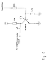
- FIG. 2 the logic inverter and level converter 5 of Fig. 1 is shown in detail.
- This converter provides the possibility, to couple the software reset signal of the control circuit 3 to the hardware reset signal of the reset circuit 4. It requires only one transistor stage with a transistor T1, which operates with a 5V supply voltage, and which is arranged as a grounded-emitter circuit.
- the grounded-emitter circuit provides the required logic conversion from signal "high” to signal “low” in case of a software reset.
- the output voltage at output A of the transistor stage T1 is 5V, which is then decoupled via the blocking diode D1 of Figure 1 for not-disturbing the "high” signal of reset circuit 4, necessary for the normal operation of the key controller 1 and therefore of the appliance.
Landscapes
- Engineering & Computer Science (AREA)
- Theoretical Computer Science (AREA)
- Physics & Mathematics (AREA)
- General Engineering & Computer Science (AREA)
- General Physics & Mathematics (AREA)
- Safety Devices In Control Systems (AREA)
Abstract
The appliance comprises a microcontroller (2) and a key
display board with a respective key controller (1). In case
of a malfunction of the key controller, not only the key
controller is reset, but also a microcontroller by a
software reset circuit (3). Both the key controller (1) and
the microcontroller (2) are then reset at the same time. The
appliance is for example a consumer electronics product
comprising digital signal processing circuits for digital
video and digital audio contents, e.g. a digital television
set or a digital video recorder. In a preferred embodiment,
also the circuits for digital video and audio processing are
reset in case of a malfunction of the key controller (1).
Description
- The present invention relates to an appliance comprising a microcontroller, a key display board and a respective key controller. Appliances of this kind are used for example in television sets, video recorders and similar consumer electronics products.
- Appliances of this kind are usually equipped at the front side with a key display board comprising buttons, via which a user can enter commands for the operation of the appliance. It may comprise also a LED or a small LCD display for providing information about operating modes. The key display board comprises further an infrared receiver for the operation of the appliance with a remote control. The user buttons and the infrared receiver are observed and operated by a key controller, which is a special microcontroller for decoding the respective user commands. The user commands are forwarded then to the microcontroller of the appliance for the operation of the appliance.
- It is known that key controllers are sensitive to electrostatic discharging or other kinds of electromagnetic radiation, which may cause a temporary malfunction or a disability of the key controller. It is therefore known to observe the correct operation of the key controller, e.g. by a watchdog circuit, which provides a reset for the key controller, when the operation of the key controller is disabled. This is called software reset, because the reset is provided by a software command signal during the operation of the appliance. Known also is a so-called hardware reset, which is activated, when the switch-on/off button of the appliance is operated. A hardware reset is therefore always activated, when the appliance is switched on.
- An appliance with a key controller is known from JP 05-158598 A2, which provides a software reset of the key controller in case of a malfunction. The key controller is coupled with a microcontroller of the appliance, which operates as a watchdog for a monitoring of the key controller. When the key controller does no more respond to the microcontroller in a defined fashion, the microcontroller provides a reset signal to the key controller in a software fashion, for resuming the operation of the key controller. In the signal path of the software reset signal an OR circuit is arranged, via which a hardware reset via an On/Off switch is provided also. Via the On/Off switch, the key controller as well as the microcontroller are reset in case of switching on the appliance.
- It is the object of the present invention, to specify an appliance as described above having a high reliability during operation.
- This object is achieved by means of the invention as specified in
claim 1. Advantageous developments of the invention are disclosed in the subclaims. - The appliance according to the invention comprises a microcontroller, a key display board and a respective key controller. In case of a malfunction of the key controller, not only the key controller is reset, but also a microcontroller by a soft-reset circuit. Both controllers can be reset at the same time. The reliability of the appliance is therefore improved, because electrostatic discharges may not only disable the key controller, but also the main microcontroller of the appliance.
- The appliance is for example a consumer electronics product comprising digital signal processing, e.g. a digital television set or a digital video recorder. The appliance therefore comprises further circuits for digital video processing and digital audio processing. In this embodiment, therefore also the circuits for digital video and audio processing are reset in case of a malfunction of the key controller.
- In a further embodiment, the appliance comprises a power supply, which provides supply voltages for a stand-by mode and a normal mode of operation. The stand-by mode provides a reduced power consumption, in which only essential circuits are active, for example circuits which are necessary for a timer mode operation or for the operation with the remote control. The supply voltages of the power supply for the ON mode can be switched on and off for switching between ON mode and stand-by mode. According to this embodiment, in case of a malfunction of the key controller the supply voltages for the ON mode are switched on and off, simulating therefore a switching to the stand-by mode and subsequently to the ON mode, and providing therefore a reset for the key controller, and the microcontroller of the appliance, as well as for all of the digital signal processing circuits.
- Preferred embodiments of the invention are now explained in more detail with reference to schematic drawings, which show:
- Fig. 1
- a circuit arrangement comprising a key controller, a microcontroller and circuitry for a hardware and a software reset;
- Fig. 2
- the logic inverter and level converter of the Fig. 1; and
- Fig. 3
- an appliance comprising a power supply, a key controller, a microcontroller and digital circuits for providing digital video and audio processing.
- The circuit arrangement as shown in Fig. 1 comprises a
key controller 1, which is coupled to amicrocontroller 2 of an appliance for an exchange of digital data, for example via an I2c bus. Thekey controller 1 is a specialized microcontroller being responsible in particular for the operation of the control keys of the appliance as well as for receiving and decoding command signals from a remote control. Thekey controller 1 is arranged on a key display board at the front side of the appliance, on which also the control keys are arranged. The key display board is usually also equipped with a small display, via which the key controller informs a user about the operating mode of the appliance. - The
microcontroller 2 is the central processor (CPU) of the appliance, which operates with software routines being stored in a memory, and which are responsible for the main operating modes of the appliance. Themicrocontroller 2 may provide for example also electronic program guide operation or videotext operation in a television set or a digital video recorder. - The circuit arrangement comprises further a
hardware reset circuit 4, which provides a hard reset for thekey controller 1 via a connection 7. Thereset circuit 4 is provided for example by a special reset integrated circuit, e.g. a MCP120 from Microchip Technology Inc., which is coupled to the power supply of the appliance for monitoring a supply voltage. In the embodiment as described with regard to Fig. 3, thiscircuit 4 monitors a supply voltage +5VE for thekey controller 1 and provides an inverted reset signal with a delay, the "On" signal for thekey controller 1. It holds therefore thekey controller 1 in reset until the supply voltage reaches stable operating level. - The circuit arrangement comprises further a
digital control circuit 3, which provides the control of digital video streams and a reset and interrupt control for peripheral and central integrated circuits of the appliance. It is for example a programmable gate array (FPGA), designed for operation within a digital video recorder or a DVD player. Thecontrol circuit 3 provides therefore a control for all of the digital video and audio signal processing circuits, and provides respective interrupts for changing operating modes, or provides resets in case of a malfunction of the appliance. - A hard-reset can be regarded therefore as a reset being caused by switching on of the appliance, and is therefore included or related to the power supply of the appliance.
- In case of a malfunction of the
key controller 1, thecontrol circuit 3 provides therefore a software reset for thekey controller 1. This reset signal is coupled via a logic inverter andlevel converter 5 to the line 7, which provides already the hardware reset for thekey controller 1. Thekey controller 1 provides then also a reset for themicrocontroller 2 via aline 6. - The hardware reset signal from
reset circuit 4 to thekey controller 1 is in this embodiment a logical "low" signal. Therefore, for the operation of thekey controller 1 the signal on line 7 is "high". Thecontrol circuit 3 provides a logical "high" for a software reset in case of a malfunction of thekey controller 1. Therefore, alogic inverter 5 and a diode D1 are necessary for coupling the software reset signal ofcontrol circuit 3 to line 7 of the hardware reset signal ofreset circuit 4. The logic inverter provides further a level concerting, because thecontrol circuit 3 operates with a 3.3V supply voltage, and thekey controller 1 with a supply voltage of 5V. - In Figure 2 the logic inverter and
level converter 5 of Fig. 1 is shown in detail. This converter provides the possibility, to couple the software reset signal of thecontrol circuit 3 to the hardware reset signal of thereset circuit 4. It requires only one transistor stage with a transistor T1, which operates with a 5V supply voltage, and which is arranged as a grounded-emitter circuit. The grounded-emitter circuit provides the required logic conversion from signal "high" to signal "low" in case of a software reset. During normal operation, the output voltage at output A of the transistor stage T1 is 5V, which is then decoupled via the blocking diode D1 of Figure 1 for not-disturbing the "high" signal ofreset circuit 4, necessary for the normal operation of thekey controller 1 and therefore of the appliance.
Claims (6)
- Appliance comprising a microcontroller (2), a key controller (1) and a reset circuit (4) for providing a hardware reset, characterized in that the appliance comprises a further reset circuit for a software reset, which resets the microcontroller (1) as well as the key controller (2) in case of a malfunction of the key controller (1).
- Appliance according to claim 1, characterized in that the appliance comprises signal processing circuits for digital video and digital audio contents, which are also reset in case of a malfunction of the key controller (1) .
- Appliance according to claim 1 or 2, characterized in that the appliance comprises further a power supply (10), which provides supply voltages for a standby-mode (5VE) and a normal mode (SWITCH-Voltages) of the appliance, and that for a software reset the supply voltages for the normal mode (SWITCH-Voltages) are switched off and on by a control circuit (3).
- Appliance according to claim 1, 2 or 3, characterized in that the reset circuit (4) for the hardware reset provides only a reset for the control circuit (3), which provides in a next step a reset for the remaining digital signal processing circuits.
- Appliance according to one of the claim 3 or 4, characterized in that an inverter and a level converter (13) is arranged between the control circuit (3) and the key controller (1).
- Appliance according to one of the claims 1 to 5, characterized in that the appliance is a DVD recorder or a personal video recorder for recording and replaying digital video recordings on a hard disc, an optical storage medium or a similar recording device.
Priority Applications (1)
| Application Number | Priority Date | Filing Date | Title |
|---|---|---|---|
| EP02292098A EP1394663A1 (en) | 2002-08-26 | 2002-08-26 | Appliance with a software reset |
Applications Claiming Priority (1)
| Application Number | Priority Date | Filing Date | Title |
|---|---|---|---|
| EP02292098A EP1394663A1 (en) | 2002-08-26 | 2002-08-26 | Appliance with a software reset |
Publications (1)
| Publication Number | Publication Date |
|---|---|
| EP1394663A1 true EP1394663A1 (en) | 2004-03-03 |
Family
ID=31197974
Family Applications (1)
| Application Number | Title | Priority Date | Filing Date |
|---|---|---|---|
| EP02292098A Ceased EP1394663A1 (en) | 2002-08-26 | 2002-08-26 | Appliance with a software reset |
Country Status (1)
| Country | Link |
|---|---|
| EP (1) | EP1394663A1 (en) |
Citations (4)
| Publication number | Priority date | Publication date | Assignee | Title |
|---|---|---|---|---|
| US4410991A (en) * | 1981-06-03 | 1983-10-18 | Gte Laboratories Incorporated | Supervisory control apparatus |
| US4531198A (en) * | 1982-05-19 | 1985-07-23 | Nissan Motor Company, Limited | Operation mode monitor for microcomputer |
| JPH05158598A (en) * | 1991-12-04 | 1993-06-25 | Casio Comput Co Ltd | Data processing device |
| US5968172A (en) * | 1997-11-12 | 1999-10-19 | Sony Corporation Of Japan | Hardware and software triggered programmable reset circuitry for serial communication device |
-
2002
- 2002-08-26 EP EP02292098A patent/EP1394663A1/en not_active Ceased
Patent Citations (4)
| Publication number | Priority date | Publication date | Assignee | Title |
|---|---|---|---|---|
| US4410991A (en) * | 1981-06-03 | 1983-10-18 | Gte Laboratories Incorporated | Supervisory control apparatus |
| US4531198A (en) * | 1982-05-19 | 1985-07-23 | Nissan Motor Company, Limited | Operation mode monitor for microcomputer |
| JPH05158598A (en) * | 1991-12-04 | 1993-06-25 | Casio Comput Co Ltd | Data processing device |
| US5968172A (en) * | 1997-11-12 | 1999-10-19 | Sony Corporation Of Japan | Hardware and software triggered programmable reset circuitry for serial communication device |
Non-Patent Citations (1)
| Title |
|---|
| PATENT ABSTRACTS OF JAPAN vol. 017, no. 557 (P - 1626) 7 October 1993 (1993-10-07) * |
Similar Documents
| Publication | Publication Date | Title |
|---|---|---|
| US6125449A (en) | Controlling power states of a computer | |
| US7930575B2 (en) | Microcontroller for controlling power shutdown process | |
| US6691201B1 (en) | Dual mode USB-PS/2 device | |
| US20020040444A1 (en) | Micro-controller having USB control unit, MC unit and oscillating circuit commonly used by the USB control unit and the MC unit | |
| US5758103A (en) | Circuit for replacing a peripheral device of a computer system and method therefor | |
| US20030135766A1 (en) | Method and apparatus to control computer system power | |
| JP3805913B2 (en) | Method for waking up computer system from standby mode and wakeup control circuit | |
| CN104158531A (en) | Electronic device | |
| JP2007516631A5 (en) | ||
| US7134030B2 (en) | Circuit controlling power supplied to a CPU based on only a power signal or a combination of a power signal and an adjustment signal | |
| EP0481466A1 (en) | Computer system equipped with extended unit including power supply | |
| KR100822321B1 (en) | Devices and methods for providing varying bias voltages to security devices | |
| US7196944B2 (en) | Voltage detection circuit control device, memory control device with the same, and memory card with the same | |
| US6903583B1 (en) | Power supply shutdown control | |
| US7193624B2 (en) | Display apparatus with power saving capability | |
| US5587675A (en) | Multiclock controller | |
| US7975152B2 (en) | Apparatus for controlling a supply of power to a second apparatus including an instant television function that operates independently of a first apparatus | |
| US7500022B2 (en) | Computer system with built-in multimedia system where multimedia system is operable independent of the operating system of the computer system and where computer system is capable of outputting video | |
| KR20220145024A (en) | Electronic apparatus and control method thereof | |
| US11374556B2 (en) | Logic circuit, sequence circuit, power supply control circuit, switching power supply device | |
| JP2006246559A (en) | Uninterruptible power supply and processing equipment | |
| KR100295987B1 (en) | How to switch the USB core's power saving / active mode | |
| KR101214160B1 (en) | Control circuit device of digital instrument and power control method for digital instrument using the same | |
| JP2011129963A (en) | Semiconductor integrated circuit device | |
| US20050180233A1 (en) | Software power control of circuit modules in a shared and distributed DMA system |
Legal Events
| Date | Code | Title | Description |
|---|---|---|---|
| PUAI | Public reference made under article 153(3) epc to a published international application that has entered the european phase |
Free format text: ORIGINAL CODE: 0009012 |
|
| AK | Designated contracting states |
Kind code of ref document: A1 Designated state(s): AT BE BG CH CY CZ DE DK EE ES FI FR GB GR IE IT LI LU MC NL PT SE SK TR |
|
| AX | Request for extension of the european patent |
Extension state: AL LT LV MK RO SI |
|
| 17P | Request for examination filed |
Effective date: 20040813 |
|
| AKX | Designation fees paid |
Designated state(s): DE FR GB IT |
|
| RAP1 | Party data changed (applicant data changed or rights of an application transferred) |
Owner name: THOMSON LICENSING |
|
| STAA | Information on the status of an ep patent application or granted ep patent |
Free format text: STATUS: THE APPLICATION HAS BEEN REFUSED |
|
| 18R | Application refused |
Effective date: 20071221 |