EP1394571A2 - Plastic optical fiber and method for producing the same - Google Patents
Plastic optical fiber and method for producing the same Download PDFInfo
- Publication number
- EP1394571A2 EP1394571A2 EP03018742A EP03018742A EP1394571A2 EP 1394571 A2 EP1394571 A2 EP 1394571A2 EP 03018742 A EP03018742 A EP 03018742A EP 03018742 A EP03018742 A EP 03018742A EP 1394571 A2 EP1394571 A2 EP 1394571A2
- Authority
- EP
- European Patent Office
- Prior art keywords
- plastic
- optical fiber
- preform
- fluorinated
- core
- Prior art date
- Legal status (The legal status is an assumption and is not a legal conclusion. Google has not performed a legal analysis and makes no representation as to the accuracy of the status listed.)
- Withdrawn
Links
Images


Classifications
-
- G—PHYSICS
- G02—OPTICS
- G02B—OPTICAL ELEMENTS, SYSTEMS OR APPARATUS
- G02B6/00—Light guides; Structural details of arrangements comprising light guides and other optical elements, e.g. couplings
-
- G—PHYSICS
- G02—OPTICS
- G02B—OPTICAL ELEMENTS, SYSTEMS OR APPARATUS
- G02B1/00—Optical elements characterised by the material of which they are made; Optical coatings for optical elements
- G02B1/04—Optical elements characterised by the material of which they are made; Optical coatings for optical elements made of organic materials, e.g. plastics
- G02B1/045—Light guides
- G02B1/046—Light guides characterised by the core material
-
- B—PERFORMING OPERATIONS; TRANSPORTING
- B29—WORKING OF PLASTICS; WORKING OF SUBSTANCES IN A PLASTIC STATE IN GENERAL
- B29D—PRODUCING PARTICULAR ARTICLES FROM PLASTICS OR FROM SUBSTANCES IN A PLASTIC STATE
- B29D11/00—Producing optical elements, e.g. lenses or prisms
- B29D11/00663—Production of light guides
- B29D11/00721—Production of light guides involving preforms for the manufacture of light guides
-
- G—PHYSICS
- G02—OPTICS
- G02B—OPTICAL ELEMENTS, SYSTEMS OR APPARATUS
- G02B1/00—Optical elements characterised by the material of which they are made; Optical coatings for optical elements
- G02B1/04—Optical elements characterised by the material of which they are made; Optical coatings for optical elements made of organic materials, e.g. plastics
- G02B1/045—Light guides
- G02B1/048—Light guides characterised by the cladding material
-
- G—PHYSICS
- G02—OPTICS
- G02B—OPTICAL ELEMENTS, SYSTEMS OR APPARATUS
- G02B6/00—Light guides; Structural details of arrangements comprising light guides and other optical elements, e.g. couplings
- G02B6/02—Optical fibres with cladding with or without a coating
- G02B6/02033—Core or cladding made from organic material, e.g. polymeric material
-
- H—ELECTRICITY
- H01—ELECTRIC ELEMENTS
- H01S—DEVICES USING THE PROCESS OF LIGHT AMPLIFICATION BY STIMULATED EMISSION OF RADIATION [LASER] TO AMPLIFY OR GENERATE LIGHT; DEVICES USING STIMULATED EMISSION OF ELECTROMAGNETIC RADIATION IN WAVE RANGES OTHER THAN OPTICAL
- H01S3/00—Lasers, i.e. devices using stimulated emission of electromagnetic radiation in the infrared, visible or ultraviolet wave range
- H01S3/05—Construction or shape of optical resonators; Accommodation of active medium therein; Shape of active medium
- H01S3/06—Construction or shape of active medium
- H01S3/063—Waveguide lasers, i.e. whereby the dimensions of the waveguide are of the order of the light wavelength
- H01S3/067—Fibre lasers
- H01S3/06708—Constructional details of the fibre, e.g. compositions, cross-section, shape or tapering
- H01S3/06716—Fibre compositions or doping with active elements
Definitions
- the present invention relates to a plastic optical fiber, and more particularly to a fluorinated plastic optical fiber that contains a rare earth component and a method for producing the plastic optical fiber.
- rare earth elements such as La, Ce, Pr, Nd, Pm, Sm, Eu, Tb, Dy, Ho, Er, Tm and Yb can emit fluorescence by 4f-4f electronic transition in a 3+ ionic state.
- Optical fibers containing such rare earth elements can amplifying an input light signal due to a stimulated emission effect.
- such optical fibers may function as an optical fiber laser that continuously generates the stimulated emission if the reflectivity of both ends of the optical fibers is properly tuned.
- a wavelength in the range of 1.3 to 1.4 ⁇ m which is a typical bandwidth for optical communication, because Pr 3+ , Nd 3+ , Dy 3+ and Tm 3+ emit fluorescence.
- Tm 3+ emits fluorescence at a wavelength in the range of 1.4 to 1.5 ⁇ m
- Er3 + emits fluorescence at a wavelength in the range of 1.5 to 1.6 ⁇ m.
- fluoride-based glass optical fibers have poor chemical durability and mechanical strength because their chemical bonds are easily broken down by moisture.
- they have a disadvantage in that the light transmittance and light amplification efficiencies of the fluoride-based glass optical fibers rapidly decreases with time.
- such optical fibers are rapidly corroded at junctions between the optical fibers because those junctions are exposed directly to air and moisture when an outer protective coating is removed from the junctions.
- plastic optical fibers have been developed for use in Gigabit Ethernet that substitute for copper wire communication in local area communication networks.
- plastic optical fibers are chemically stable and exhibit superior usability at normal temperature ranges.
- the conventional plastic optical fibers have a disadvantage in that their application for an infrared region is restricted because a hydrocarbon (C-H) high polymer chain structure absorbs light having an infrared wavelength.
- the object of the present invention is to provide a plastic optical fiber with improved chemical durability, mechanical strength and thermal resistance, and a process for producing the same.
- an optical fiber of core-cladding structure wherein the core material essentially consists of fluorinated plastic, which contains a rare earth component, and the cladding material does not contain a rare earth component but essentially consists of fluorinated plastic having a refractive index lower than that of the core material.
- fluorinated plastic having a carbon-fluoride (C-F) bond transmits infrared light well and thus allows for infrared communication when used as an optical fiber.
- fluorinated plastic is widely applicable because it has remarkably superior chemical durability and can be used under broad range of temperature as compared to existing hydrocarbon-based plastics.
- amorphous fluorinated plastic is a promising material as an optical fiber for communication, due to its low Rayleigh scattering loss. TeflonTM and CytopTM are examples of fluorinated plastic.
- the optical fiber may further include a protective layer formed from a polymer on the outer surface of the core-cladding structure.
- a process for producing a plastic optical fiber includes the steps of:
- a method for producing a plastic optical fiber includes the steps of:
- FIG. 1 shows a structure of a plastic optical fiber 10 in accordance with one embodiment of the present invention.
- the plastic optical fiber 10 is basically formed as a core 11 and a cladding 12 structure. It is also possible to provide a protective layer or shield layer 13 on the outer surface thereof for protecting the plastic optical fiber 10 of the core-cladding structure from air or moisture.
- the optical fiber 10 uses fluorinated plastic which contains a rare earth component, as a core material, and uses a polymer chain which essentially consists of connected -[CF 2 ] n - monomers without containing a rare earth component and has a lower refractive index than the core material, as a cladding material.
- the optical fiber 10 is produced by a melting and drawing technique.
- the "rare earth component” comprises any of the following combinations A) to E):
- the rare earth component may be limited to a fluorinated glass or sulfide glass composition to which at least one of the lanthanide elements are added in a concentration of 0.01 ⁇ 10%.
- the fluorinated plastic is formed from a polymer chain which essentially consists of bonded -[CF 2 ] n - monomers.
- a fluorinated plastic may be TeflonTM (AF, FEP, PFA, PFTF), CytopTM and the like.
- Fluorinated plastic cladding 12 which encloses the fluorinated plastic core 11
- the cladding 12 is formed from a polymer chain which essentially consists of bonded -[CF 2 ] n - monomers without containing a rare earth component and has a refractive index lower than that of the core by 0.01 ⁇ 10%.
- the polymer coating may be selectively applied when it is required for coloring the fluorinated optical fiber or maintaining the diameter of the optical fiber.
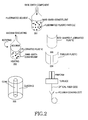
- FIG. 2 illustrates a process for producing a plastic optical fiber in accordance an embodiment of the present invention.
- rare earth component powder having a particle diameter distributed in the range of 0.1 to 10 ⁇ m is evenly dispersed into a fluorinated solvent(FluorinertTM), in a volumetric ratio of 0.01 to 0.10, in which solvent fluorinated plastic powder having a particle diameter of 0.1 to 10 ⁇ m has been dispersed, in a volumetric ratio of 0.01 to 0.3 (step 201).
- a solution prepared through the above procedure is filled into a test tube, and the test tube is rotated to a rotaed speed in the rage of 10 to 2000 rpm and heated to a temperature in the range of 100 to 300°C. Where the rotation speed and the temperature are variable for the solution viscosity, the tube is then vacuum-evacuated so that the solvent is evaporated, and the fluorinated plastic is cured. (Step 202).
- a rod-shaped or tubular core preform is assembled at the center of a fluorinated plastic cladding preform which has been prepared by a extruding method or the like and does not contains a rare earth component (step 205).
- the fluorinated plastic preform prepared through the afore-mentioned procedure is softened by being heated (e.g., in a furnace) to a temperature in the range of 150 to 500 °C.
- the preform softened in this manner is produced into an optical fiber by a method of elongating the preform, i.e., a extruding method (step 206).
- a vacuum is applied to the center of the preform while the preform is being heated, empty voids present between the core and the cladding are contracted and removed.
- empty voids at the center of the core are contracted and removed by the vacuum.
- a final step for putting a polymer coating film over the optical fiber after the optical fiber is drawn may be included.
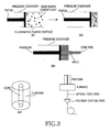
- FIG. 3 illustrates a process for producing a plastic optical fiber in accordance with another embodiment of the present invention.
- a fluorinated plastic powder having a particle diameter distributed in the range of 0.1 to 10 ⁇ m, in a volumetric ratio of 0.50 to 0.99, and a rare earth component powder having a particle diameter of 0.1 to 10 ⁇ m, in a volumetric ratio of 0.01 to 0.50, are evenly mixed (step 301).
- a rod-shaped core preform is produced by filling the mixed powder into a pressure container, heating the powder to a temperature in the range of 150 to 500°C, and applying a pressure in the range of 10 3 to 10 7 Pa (step 302). At this time, if the mixed powder is drawn at a temperature in the range of 150 to 500°C, it is possible to produce a rod-shaped core preform (step 303).
- a rod-shaped or tubular core preform is assembled at the center of a fluorinated plastic cladding preform which has been prepared by a extruding method and the like and does not contains a rare earth component (step 304).
- the fluorinated plastic preform prepared through the afore-mentioned procedure is softened by being heated (e.g., in a furnace) to a temperature in the range of 150 to 500 °C.
- the preform softened in this manner is formed into an optical fiber by a method of elongating the preform, i.e., a extruding method (step 305).
- a vacuum is applied to the center of the preform while the preform is being heated, empty voids present between the core and the cladding are contracted and removed.
- empty voids at the center of the core are contracted and removed by the vacuum.
- a step for putting a polymer coating film over the optical fiber after the optical fiber is drawn may be included (step 306).
- TeflonTM FEP core preform which contains 10 volume% of a rare earth component having a compositional formula, (GeS 2 -As 2 S 3 -CsBr-Ga 2 S 3 ) 0.998 (TmBr 3 ) 0.002, using the following method.
- a rod-shaped core preform is produced by filling the mixed powder into a pressure container, and applying a pressure of 10 6 Pa at a temperature of 340°C.
- FIG. 4 shows a fluorescence emission spectrum of the optical fiber produced in accordance with the above example.
- the spectrum was obtained by measuring fluorescence within the range of infrared wavelengths using a spectroscope.
- the fluorescence was produced from a sample after a laser beam having a wavelength of 800 nm was entered into the center of the sample.
- a fluorescence emission which can amplify an optical signal of S-band (wavelength bandwidth of 1450 to 1520 nm) was observed.
- the plastic optical fiber can overcome the problems of the prior art and has advantages in that it has excellent improved chemical durability, mechanical strength and thermal resistance.
Landscapes
- Physics & Mathematics (AREA)
- Optics & Photonics (AREA)
- General Physics & Mathematics (AREA)
- Engineering & Computer Science (AREA)
- Electromagnetism (AREA)
- Ophthalmology & Optometry (AREA)
- Manufacturing & Machinery (AREA)
- Mechanical Engineering (AREA)
- Health & Medical Sciences (AREA)
- Plasma & Fusion (AREA)
- Optical Fibers, Optical Fiber Cores, And Optical Fiber Bundles (AREA)
- Lasers (AREA)
- Surface Treatment Of Glass Fibres Or Filaments (AREA)
Abstract
Description
- FIG. 1
- shows a cross-section of a plastic optical fiber in accordance with an embodiment of the present invention;
- FIG. 2
- illustrates a process for producing a plastic optical fiber in accordance with an embodiment of the present invention;
- FIG. 3
- illustrates a process for producing a plastic optical fiber in accordance with another embodiment of the present invention; and
- FIG. 4
- shows a fluorescence emission spectrum of an optical fiber produced in accordance with an embodiment of the present invention.
Claims (15)
- An optical fiber having a core-cladding structure, comprising:a core material essentially consists of fluorinated plastic which contains a rare earth component; anda cladding material which does not contain a rare earth component but essentially consists of fluorinated plastic having a refractive index lower than that of the core material.
- The plastic optical fiber according to claim 1, wherein the rare earth component comprises any one of the following combinations A) to E):A) (Y1-nLan)1-mLnmX3 (m = 0.0001 ~ 1.0, n = 0 ~1.0);B) (La1-mLnm)2S3 (m = 0.0001 ~ 1.0);C) (ZrF3-BaF2-LaF3-AlF3-NaF)1-m(LnF3)m (m = 0.0001 ~ 0.1);D) (InF3-GaF3-PbF2-CdF3)1-m(LnF3)m (m = 0.0001 ~ 0.1); andE) (RX-GeS2-As2S3-Ga2S3)1-m(LnX3)m (m = 0.0001 ~ 0.1).
- The plastic optical fiber according to claim 2, wherein Ln is a lanthanide metallic component which includes at least one of Ce, Pr, Nd, Sm, Eu, Gd, Tb, Dy, Ho, Er, Tm, and Yb.
- The plastic optical fiber according to claim 2, wherein R is an alkali metal component which includes at least one of Li, Na, K, Rb and Cs.
- The plastic optical fiber according to claim 2, wherein X is a halogen which includes at least one of F, Cl, Br and I.
- The plastic optical fiber according to claim 1, wherein the refractive index of the cladding material is lower than that of the core material by 0.01 to 10%.
- The plastic optical fiber according to any one of claims 1 to 6, wherein the fluorinated plastic comprises a polymer chain which essentially consists of bonded -[CF2]n- monomers.
- The plastic optical fiber according to claim 1, wherein the optical fiber further comprises a protective layer formed from a polymer on the outer surface of the cladding.
- A process for producing a plastic optical fiber comprising the steps of:filling a fluorinated solvent with fluorinated plastic powder dispersed therein and a rare earth component into a reactor;forming a core preform by evaporating the fluorinated solvent through a vacuum-evacuation of an interior of the reactor while heating and rotating the reactor, and then by curing a resulting fluorinated plastic;assembling the core preform at the center of a cladding preform which does not contain a rare earth component but essentially consists of fluorinated plastic having a refractive index lower than that of a core material to produce a fluorinated plastic preform;heating and softening the fluorinated plastic preform; anddrawing an optic fiber from the softened fluorinated plastic preform.
- The process according to claim 9, wherein a dispersed content of the fluorinated plastic powder is 0.01 to 0.30 in volumetric ratio, and a dispersed content of the rare earth powder is 0.01 to 0.10 in volumetric ratio.
- The process according to claim 9, wherein the step of forming the core preform by curing the resulting fluorinated plastic comprises the steps of:evaporating a solvent by vacuum exhaustion of a interior of the reactor while heating the reactor to a temperature of 100 to 300°C; andforming a rod-shaped fluorinated plastic core preform by lowering a temperature while reducing a rotation speed of the reactor when the curing of the resulting fluorinated plastic begins.
- The process according to claim 9, wherein the step of forming the core preform by curing the resulting fluorinated plastic comprises the steps of:evaporating a solvent by vacuum exhaustion of a interior of the reactor while heating the reactor to a temperature of 100 to 300°C; andforming a tubular fluorinated plastic core preform by lowering a temperature while maintaining a rotation speed of the reactor when the curing of the resulting fluorinated plastic begins.
- The process according to claim 11 or 12, wherein the step of heating and softening the fluorinated plastic preform is performed at a temperature of 150 to 500°C.
- The process according to claim 9, further comprising the step of coating a polymer layer when drawing the optic fiber from the softened fluorinated plastic preform.
- A method for producing a plastic optical fiber comprising the steps of:mixing a fluorinated plastic powder and a rare earth component powder and filling the mixed powder into a pressure container;forming a core preform by heating and extruding the mixed powder;assembling the core preform at a center of a cladding preform which does not contain a rare earth component but essentially consists of fluorinated plastic having a refractive index lower than that of a core material to produce a fluorinated plastic preform;heating and softening the fluorinated plastic preform; anddrawing an optical fiber from the fluorinated plastic preform.
Applications Claiming Priority (2)
| Application Number | Priority Date | Filing Date | Title |
|---|---|---|---|
| KR10-2002-0050470A KR100433905B1 (en) | 2002-08-26 | 2002-08-26 | Plastic optical fiber and method for fabricating thereof |
| KR2002050470 | 2002-08-26 |
Publications (2)
| Publication Number | Publication Date |
|---|---|
| EP1394571A2 true EP1394571A2 (en) | 2004-03-03 |
| EP1394571A3 EP1394571A3 (en) | 2004-04-07 |
Family
ID=31492901
Family Applications (1)
| Application Number | Title | Priority Date | Filing Date |
|---|---|---|---|
| EP03018742A Withdrawn EP1394571A3 (en) | 2002-08-26 | 2003-08-26 | Plastic optical fiber and method for producing the same |
Country Status (5)
| Country | Link |
|---|---|
| US (2) | US6978077B2 (en) |
| EP (1) | EP1394571A3 (en) |
| JP (1) | JP2004086216A (en) |
| KR (1) | KR100433905B1 (en) |
| CN (1) | CN1234029C (en) |
Families Citing this family (13)
| Publication number | Priority date | Publication date | Assignee | Title |
|---|---|---|---|---|
| US6803335B2 (en) * | 2001-08-03 | 2004-10-12 | The University Of Southampton | Gallium lanthanum sulfide glasses and optical waveguides and devices using such glasses |
| US6901231B1 (en) * | 2002-03-25 | 2005-05-31 | Ricoh Company, Ltd. | Developing apparatus, developing method, image forming apparatus, image forming method and cartridge thereof |
| KR100638436B1 (en) * | 2004-11-04 | 2006-10-24 | 주식회사 효성 | Graded index type plastic optical fiber and manufacturing method thereof |
| CN100538420C (en) * | 2005-05-09 | 2009-09-09 | 三菱丽阳株式会社 | Plastic optical fiber cable |
| US7680390B2 (en) * | 2007-03-16 | 2010-03-16 | Fujikura Ltd. | Polymer clad optical fiber |
| EP2769386A4 (en) * | 2011-10-17 | 2016-02-17 | Services Petroliers Schlumberger | DUAL-USE CABLE WITH FIBER OPTIC ENCAPSULATION FOR USE IN WELLBORE OPERATIONS |
| WO2014004026A1 (en) | 2012-06-28 | 2014-01-03 | Schlumberger Canada Limited | High power opto-electrical cable with multiple power and telemetry paths |
| US11725468B2 (en) | 2015-01-26 | 2023-08-15 | Schlumberger Technology Corporation | Electrically conductive fiber optic slickline for coiled tubing operations |
| US10049789B2 (en) | 2016-06-09 | 2018-08-14 | Schlumberger Technology Corporation | Compression and stretch resistant components and cables for oilfield applications |
| CN110361106B (en) * | 2019-07-15 | 2020-11-20 | 燕山大学 | A high-sensitivity temperature sensing method for near-infrared fluorescence |
| CN110687628A (en) * | 2019-10-22 | 2020-01-14 | 南京春辉科技实业有限公司 | Plastic fluorescent optical fiber and manufacturing method thereof |
| CN111061002B (en) * | 2019-12-07 | 2024-02-02 | 南京春辉科技实业有限公司 | Plastic fluorescent optical fiber and preparation method thereof |
| CN112198585B (en) * | 2020-09-01 | 2021-05-18 | 威海长和光导科技有限公司 | A single-mode step-type polymer optical fiber and preparation method thereof |
Family Cites Families (20)
| Publication number | Priority date | Publication date | Assignee | Title |
|---|---|---|---|---|
| US4015217A (en) | 1961-10-27 | 1977-03-29 | American Optical Corporation | Means for producing and amplifying optical energy |
| BE630377A (en) | 1962-03-29 | |||
| US4161500A (en) | 1977-10-14 | 1979-07-17 | E. I. Du Pont De Nemours And Company | Process for low attenuation methacrylate optical fiber |
| JPS60119509A (en) | 1983-12-02 | 1985-06-27 | Sumitomo Electric Ind Ltd | Manufacture of preform for plastic optical fiber |
| JPS62172307A (en) * | 1986-01-27 | 1987-07-29 | Mitsubishi Rayon Co Ltd | plastic light transmitting fiber |
| EP0250996A3 (en) * | 1986-06-21 | 1988-06-01 | Daikin Industries, Limited | Optical fibers |
| GB2196148B (en) * | 1986-09-09 | 1990-03-28 | Central Glass Co Ltd | Optical fiber using vinylidene fluoride base ternary copolymer as cladding material |
| US5204435A (en) * | 1989-10-30 | 1993-04-20 | Shin-Etsu Chemical Co., Ltd. | Optical fibers and core-forming compositions |
| JPH05241036A (en) | 1990-08-16 | 1993-09-21 | Yasuhiro Koike | Plastic optical transmission body and production thereof |
| JPH06102442A (en) * | 1992-09-22 | 1994-04-15 | Asahi Chem Ind Co Ltd | Heat resistant and flame retarding plastic optical fiber cord |
| JPH075331A (en) * | 1993-06-18 | 1995-01-10 | Sumitomo Electric Ind Ltd | Method for manufacturing plastic optical fiber preform |
| US5861129A (en) | 1995-09-13 | 1999-01-19 | Katoot; Mohammad W. | Polymer optical fibers and process for manufacture thereof |
| JPH09178958A (en) * | 1995-12-27 | 1997-07-11 | Sumitomo Wiring Syst Ltd | Production of preform for distributed refractive index plastic optical fiber |
| US5774620A (en) * | 1996-01-30 | 1998-06-30 | Nippon Telegraph And Telephone Corporation | Fluoride glass fiber |
| US6205281B1 (en) * | 1997-05-27 | 2001-03-20 | Corning Incorporated | Fluorinated rare earth doped glass and glass-ceramic articles |
| US6292292B1 (en) | 2000-02-18 | 2001-09-18 | Photon-X | Rare earth polymers, optical amplifiers and optical fibers |
| US6699406B2 (en) | 1999-03-19 | 2004-03-02 | Rutgers, The State University | Rare earth doped host materials |
| DE19914743A1 (en) * | 1999-03-31 | 2001-01-25 | Siemens Ag | Optical core |
| EP1272336A2 (en) | 2000-04-12 | 2003-01-08 | Nanoptics, Inc. | Method and apparatus for manufacturing plastic optical transmission medium |
| US20030024276A1 (en) * | 2001-05-30 | 2003-02-06 | 3M Innovative Properties Company | Method of manufacture of an optical waveguide article including a fluorine-containing zone |
-
2002
- 2002-08-26 KR KR10-2002-0050470A patent/KR100433905B1/en not_active Expired - Fee Related
-
2003
- 2003-08-12 US US10/639,354 patent/US6978077B2/en not_active Expired - Fee Related
- 2003-08-25 CN CNB031549179A patent/CN1234029C/en not_active Expired - Fee Related
- 2003-08-26 JP JP2003301403A patent/JP2004086216A/en not_active Abandoned
- 2003-08-26 EP EP03018742A patent/EP1394571A3/en not_active Withdrawn
-
2005
- 2005-03-22 US US11/087,016 patent/US6955774B2/en not_active Expired - Fee Related
Also Published As
| Publication number | Publication date |
|---|---|
| CN1485630A (en) | 2004-03-31 |
| US6978077B2 (en) | 2005-12-20 |
| CN1234029C (en) | 2005-12-28 |
| EP1394571A3 (en) | 2004-04-07 |
| US20050163452A1 (en) | 2005-07-28 |
| US20040037539A1 (en) | 2004-02-26 |
| KR100433905B1 (en) | 2004-06-04 |
| KR20040019445A (en) | 2004-03-06 |
| US6955774B2 (en) | 2005-10-18 |
| JP2004086216A (en) | 2004-03-18 |
Similar Documents
| Publication | Publication Date | Title |
|---|---|---|
| US7272285B2 (en) | Fiber waveguides and methods of making the same | |
| EP1394571A2 (en) | Plastic optical fiber and method for producing the same | |
| Blanc et al. | Formation and applications of nanoparticles in silica optical fibers | |
| CN1275891C (en) | Glass fibre with at least two glass layers | |
| CN102411168B (en) | Low loss optical fiber designs and methods for their manufacture | |
| US5251062A (en) | Tellurite glass and fiber amplifier | |
| CN1261332A (en) | Composition for use in optical waveguide articles and method of making continuous clad fiber filaments | |
| WO2002084345A1 (en) | High index-contrast fiber waveguides and applications | |
| WO2004052078A2 (en) | High power low-loss fiber waveguide | |
| CA2288888A1 (en) | Fluorinated rare earth doped glass and glass-ceramic articles | |
| EP1394909A2 (en) | Amplifying optical fiber and method for fabricating the same | |
| WO2003002477A1 (en) | Borosilicate cladding glasses for germanate core thulium-doped amplifiers | |
| EP0773195B1 (en) | Glass body for optical fiber, use thereof, optical fiber, and method of making it | |
| Righini et al. | Integrated optical amplifiers and microspherical lasers based on erbium-doped oxide glasses | |
| CN116375349A (en) | A bismuth-doped germanosilicate glass fiber with high-efficiency broadband emission in the L+U band and its preparation method and application | |
| JPH0952731A (en) | Fluorophosphoric acid glass, optical fiber using the same and its production | |
| Shakhanov et al. | All-silica optical fibers with reduced losses beyond two microns | |
| Harrington | Mid-IR and Infrared Fibers | |
| Hilton Sr et al. | Production of far infrared glass fiber | |
| JPH0813692B2 (en) | Chalcogenide glass fiber with core-clad structure | |
| CN121020976A (en) | Redrawable glass, optical waveguides using such glass, and their applications | |
| JPH05208847A (en) | Fluorophosphate laser glass waveguide | |
| Poulain et al. | Fluoride glass fiber sources: Problems and prospects |
Legal Events
| Date | Code | Title | Description |
|---|---|---|---|
| PUAI | Public reference made under article 153(3) epc to a published international application that has entered the european phase |
Free format text: ORIGINAL CODE: 0009012 |
|
| PUAL | Search report despatched |
Free format text: ORIGINAL CODE: 0009013 |
|
| 17P | Request for examination filed |
Effective date: 20030826 |
|
| AK | Designated contracting states |
Kind code of ref document: A2 Designated state(s): AT BE BG CH CY CZ DE DK EE ES FI FR GB GR HU IE IT LI LU MC NL PT RO SE SI SK TR |
|
| AX | Request for extension of the european patent |
Extension state: AL LT LV MK |
|
| AK | Designated contracting states |
Kind code of ref document: A3 Designated state(s): AT BE BG CH CY CZ DE DK EE ES FI FR GB GR HU IE IT LI LU MC NL PT RO SE SI SK TR |
|
| AX | Request for extension of the european patent |
Extension state: AL LT LV MK |
|
| RIC1 | Information provided on ipc code assigned before grant |
Ipc: 7C 09K 11/77 B Ipc: 7H 01S 3/067 B Ipc: 7B 29D 11/00 B Ipc: 7G 02B 6/16 B Ipc: 7G 02B 1/04 A |
|
| AKX | Designation fees paid |
Designated state(s): DE FR GB |
|
| 17Q | First examination report despatched |
Effective date: 20050104 |
|
| STAA | Information on the status of an ep patent application or granted ep patent |
Free format text: STATUS: THE APPLICATION HAS BEEN WITHDRAWN |
|
| 18W | Application withdrawn |
Effective date: 20060317 |