EP1394427A1 - Table device - Google Patents
Table device Download PDFInfo
- Publication number
- EP1394427A1 EP1394427A1 EP02720496A EP02720496A EP1394427A1 EP 1394427 A1 EP1394427 A1 EP 1394427A1 EP 02720496 A EP02720496 A EP 02720496A EP 02720496 A EP02720496 A EP 02720496A EP 1394427 A1 EP1394427 A1 EP 1394427A1
- Authority
- EP
- European Patent Office
- Prior art keywords
- slider
- guide rail
- screw
- table apparatus
- hole
- Prior art date
- Legal status (The legal status is an assumption and is not a legal conclusion. Google has not performed a legal analysis and makes no representation as to the accuracy of the status listed.)
- Granted
Links
Images












Classifications
-
- F—MECHANICAL ENGINEERING; LIGHTING; HEATING; WEAPONS; BLASTING
- F16—ENGINEERING ELEMENTS AND UNITS; GENERAL MEASURES FOR PRODUCING AND MAINTAINING EFFECTIVE FUNCTIONING OF MACHINES OR INSTALLATIONS; THERMAL INSULATION IN GENERAL
- F16C—SHAFTS; FLEXIBLE SHAFTS; ELEMENTS OR CRANKSHAFT MECHANISMS; ROTARY BODIES OTHER THAN GEARING ELEMENTS; BEARINGS
- F16C29/00—Bearings for parts moving only linearly
- F16C29/005—Guide rails or tracks for a linear bearing, i.e. adapted for movement of a carriage or bearing body there along
-
- B—PERFORMING OPERATIONS; TRANSPORTING
- B23—MACHINE TOOLS; METAL-WORKING NOT OTHERWISE PROVIDED FOR
- B23Q—DETAILS, COMPONENTS, OR ACCESSORIES FOR MACHINE TOOLS, e.g. ARRANGEMENTS FOR COPYING OR CONTROLLING; MACHINE TOOLS IN GENERAL CHARACTERISED BY THE CONSTRUCTION OF PARTICULAR DETAILS OR COMPONENTS; COMBINATIONS OR ASSOCIATIONS OF METAL-WORKING MACHINES, NOT DIRECTED TO A PARTICULAR RESULT
- B23Q1/00—Members which are comprised in the general build-up of a form of machine, particularly relatively large fixed members
- B23Q1/0009—Energy-transferring means or control lines for movable machine parts; Control panels or boxes; Control parts
- B23Q1/0018—Energy-transferring means or control lines for movable machine parts; Control panels or boxes; Control parts comprising hydraulic means
-
- B—PERFORMING OPERATIONS; TRANSPORTING
- B23—MACHINE TOOLS; METAL-WORKING NOT OTHERWISE PROVIDED FOR
- B23Q—DETAILS, COMPONENTS, OR ACCESSORIES FOR MACHINE TOOLS, e.g. ARRANGEMENTS FOR COPYING OR CONTROLLING; MACHINE TOOLS IN GENERAL CHARACTERISED BY THE CONSTRUCTION OF PARTICULAR DETAILS OR COMPONENTS; COMBINATIONS OR ASSOCIATIONS OF METAL-WORKING MACHINES, NOT DIRECTED TO A PARTICULAR RESULT
- B23Q1/00—Members which are comprised in the general build-up of a form of machine, particularly relatively large fixed members
- B23Q1/25—Movable or adjustable work or tool supports
- B23Q1/44—Movable or adjustable work or tool supports using particular mechanisms
- B23Q1/56—Movable or adjustable work or tool supports using particular mechanisms with sliding pairs only, the sliding pairs being the first two elements of the mechanism
- B23Q1/58—Movable or adjustable work or tool supports using particular mechanisms with sliding pairs only, the sliding pairs being the first two elements of the mechanism a single sliding pair
-
- F—MECHANICAL ENGINEERING; LIGHTING; HEATING; WEAPONS; BLASTING
- F16—ENGINEERING ELEMENTS AND UNITS; GENERAL MEASURES FOR PRODUCING AND MAINTAINING EFFECTIVE FUNCTIONING OF MACHINES OR INSTALLATIONS; THERMAL INSULATION IN GENERAL
- F16C—SHAFTS; FLEXIBLE SHAFTS; ELEMENTS OR CRANKSHAFT MECHANISMS; ROTARY BODIES OTHER THAN GEARING ELEMENTS; BEARINGS
- F16C29/00—Bearings for parts moving only linearly
- F16C29/004—Fixing of a carriage or rail, e.g. rigid mounting to a support structure or a movable part
-
- F—MECHANICAL ENGINEERING; LIGHTING; HEATING; WEAPONS; BLASTING
- F16—ENGINEERING ELEMENTS AND UNITS; GENERAL MEASURES FOR PRODUCING AND MAINTAINING EFFECTIVE FUNCTIONING OF MACHINES OR INSTALLATIONS; THERMAL INSULATION IN GENERAL
- F16C—SHAFTS; FLEXIBLE SHAFTS; ELEMENTS OR CRANKSHAFT MECHANISMS; ROTARY BODIES OTHER THAN GEARING ELEMENTS; BEARINGS
- F16C29/00—Bearings for parts moving only linearly
- F16C29/04—Ball or roller bearings
- F16C29/06—Ball or roller bearings in which the rolling bodies circulate partly without carrying load
- F16C29/0633—Ball or roller bearings in which the rolling bodies circulate partly without carrying load with a bearing body defining a U-shaped carriage, i.e. surrounding a guide rail or track on three sides
-
- F—MECHANICAL ENGINEERING; LIGHTING; HEATING; WEAPONS; BLASTING
- F16—ENGINEERING ELEMENTS AND UNITS; GENERAL MEASURES FOR PRODUCING AND MAINTAINING EFFECTIVE FUNCTIONING OF MACHINES OR INSTALLATIONS; THERMAL INSULATION IN GENERAL
- F16C—SHAFTS; FLEXIBLE SHAFTS; ELEMENTS OR CRANKSHAFT MECHANISMS; ROTARY BODIES OTHER THAN GEARING ELEMENTS; BEARINGS
- F16C2322/00—Apparatus used in shaping articles
- F16C2322/39—General buildup of machine tools, e.g. spindles, slides, actuators
Definitions
- This invention relates to a linear guide device and a table apparatus with the linear guide device and, more in particular, it relates to a linear guide device having a structure suitable to be used in vacuum or depressurized circumstances, as well as a table apparatus with the linear guide device.
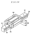
- Fig. 26 shows a perspective view of an existent linear guide device.
- the linear guide device comprises a guide rail 51 and a slider 60.
- the slider 60 comprises a slider main body 52, end caps 53 and side seals 54.
- the linear guide device, a not illustrated guide rail-side member and a not illustrated slider-side member constitute a table apparatus.
- the not illustrate guide rail-side member is, for example, a substructure to which the guide rail is secured and the not illustrated slider-side member is, for example, a table secured to the slider main body.
- the guide rail 51 is extended in one direction and has rolling element grooves 55 on both lateral side wall surfaces in the longitudinal direction.
- the guide rail 51 is attached to the guide rail-side member by using rail attaching screw holes 56 by means of not illustrated bolts.
- the slider-side member is attached to the slider main body 52 by using four slider main body attaching screw holes 84 by means of not illustrated bolts.
- the slider main body 52 is of a substantially U-shaped cross section with a concave portion in the inside.
- the slider 60 is completed.
- the end cap 53 and the side seal 54 are integrally attached to the slider main body 52 by using assembling screw holes 85 and not illustrated bolts.
- Four assembling screw holes 85 are provided on each side of the slider main body 52.
- rolling elements are loaded in a predetermined circulation channel formed in the slider 60.
- the slider 60 moves on the guide rail 51 by the rolling motion of the rolling elements between the guide rail 51 and the slider 60 when they conduct endless circulation in the circulation channel.
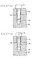
- Fig. 27(a) is an enlarged view of a main portion showing a state of an attaching screw 21 which is screwed and clamped in a receiving portion of the slider main body 52.
- the receiving portion is, for example, an attaching screw hole 84
- the slider-side member 70 is attached to the slider main body 52 by screwing and clamping the attaching screw 21 in the attaching screw hole 84.
- a state of an assembling screw which is screwed and clamped in the assembling screw hole 85 and a state of a rail attaching screw which is screwed and clamped in a rail attaching screw hole 56 are identical to the attaching screw 21 with respect to the surrounding conditions of the bolt.
- a gas reservoir 23 as a gap remains at the bottom of the screw hole.
- the gas reservoir forms "dead space". With evacuation of air by a vacuum pump, a small amount of air slowly and gradually passes through a contacting area between the head of the screw 21 and the slider side member 70. The passing air continuously leaks into the vacuum or depressurized circumstances, even though the screw 21 is tightened completely. Accordingly, it takes a considerable time till such leakage stops, that is, till the pressure in the portion of the gas reservoir 23 is equal to the outside pressure. It takes much time, particularly, in a case where the extent of the outside vacuum condition is high.
- the gas reservoir causing such a problem is present on every portions where members constituting the table apparatus with the linear guide device are joined to each other by combination of screws and screw holes.
- a method to remove the accumulated air in the gas reservoir 23 instantly by using a special screw (gas vent bolt) 25 has a gas vent hole 24 that axially perforates through a central portion.
- another member 26 is sometimes attached on the slider-side member 29 to which the slider main body 52 is directly attached.
- a special screw 25 for example, with a gas vent hole 24
- the space 28 is tightly sealed to the outside by another member 26 and also forms a gas reservoir. Accordingly, even though the special screw 25 is used, both the gas reservoir 23 at the bottom of the screw hole and the space 28 constitute "dead space", and a small amount of air leaks into the vacuum circumstance or depressurized circumstance continuously and gradually.
- the present invention intends to provide a linear guide device suitable to be used in vacuum or depressurized circumstances, as well as a table apparatus with the linear guide device without using any special screws formed with the gas vent hole.
- the invention described in claim 1 provides a table apparatus in which a joining member for joining a predetermined combination for a plurality of members constituting a table apparatus comprising a guide rail, a slider, a guide rail-side member to which the guide rail is attached and a slider-side member to which the slider is attached, and a receiving portion for receiving the joining member are disposed to the members comprising the combination described above, wherein a channel that is in communication from a gap formed between the joining member and the receiving portion by receiving the joining member in the receiving portion to the outside of the table apparatus is formed to at least one of the members that constitute the table apparatus.
- the channel is formed in communication from the gap of a gas reservoir formed between the joining member and the receiving portion to the outside of the table apparatus.
- the air in the gas reservoir is easily discharged through the channel to the outside of the table apparatus.
- the receiving portion receives the joining member and provides a securing and joining structure relative to the joining member.
- the joining member includes a screw (bolt) or a pin and the receiving portion includes a screw hole (bolt hole), an insertion hole to insert the screw (bolt) or a pin hole.
- the receiving portion is formed to a member constituting the table apparatus. In the table apparatus, the receiving portion is formed to the guide rail, the slider, the guide rail-side member to which the guide rail is attached or the slider-side member to which the slider is attached. In the slider, the receiving portion is formed to one or all of the slider main body, the end cap, and the side seal.
- the channel is formed to any of the members that constitute the table apparatus so as to be in communication with the gap.
- the invention described in claim 2 provides a table apparatus as defined in claim 1, wherein the channel is a gas vent hole that perforates through at least one of the members constituting the table apparatus.
- the air in the gap which forms the gas reservoir between the joining member and the receiving portion is easily discharged to the outside of the table apparatus through the perforated gas vent hole.
- the gas vent hole is preferably perforated through the member constituting the table apparatus so as to be substantially in perpendicular to the direction along which the receiving portion is formed.
- the gas vent hole is preferably perforated through the member that constitutes the table apparatus in substantially axial direction along which the receiving portion is formed.
- the invention described in claim 3 provides a table apparatus as defined in claim 1, wherein the channel is a groove formed on the surface of the member constituting the table apparatus.
- the gap forming the gas reservoir between the joining member and the receiving portion is in communication with the outside of the table through the groove, and the air in the gas reservoir is easily discharged to the outside of the table apparatus.
- the invention described in claim 4 provides a table apparatus as defined in claim 3, wherein the receiving portion is a receiving portion with which the slider and the slider-side member are combined and joined to each other, that is, a plurality of attaching screw holes that open on each of the surfaces of the slider and the slider-side member combined and opposed to each other, the groove is formed on at least one of the surfaces of the slider and the slider-side member opposed to each other, and the groove is in contiguous from the opening of the attaching screw hole to the end of a portion where the opposing surfaces are in contact with each other.
- the invention described in claim 5 provides a table apparatus as defined in claim 3, wherein the receiving portion is a receiving portion with which the guide rail and the guide rail-side member are joined, that is, a plurality of attaching screw holes that open on each of the surfaces of the guide rail and the guide rail-side member combined and opposed to each other, the groove is formed on at least one of the surfaces of the guide rail and the guide rail-side member combined and opposed to each other, the groove is formed on at least one of the surfaces of the guide rail and the guide rail-side member combined and opposed to each other, and the groove is in contiguous from the opening of the attaching screw hole to the end of a portion where the opposing surfaces are in contact with each other.
- the invention described in claim 6 provides a table apparatus as defined in claim 4 or claim 5, wherein the groove has a communication channel that is in communication to a surface of the member in which the groove is formed and to the surface is one of the surfaces on which the groove is not formed.
- the groove is in communication with the outside of the table apparatus through the communication channel. Accordingly, the air in the gap which forms the gas reservoir between the attaching screw hole and the attaching screw is easily discharged through the groove and the communication channel to the outside of the table apparatus.
- the communication channel includes a channel perforating through the inside of the member constituting the table apparatus on which the groove is formed, and another groove on a surface of the member constituting the table apparatus in which the groove is formed and the surface is adjacent with the surface where the groove is formed.
- the invention described in claim 7 provides a table apparatus in which a joining member for joining a predetermined combination for a plurality of members constituting a table apparatus comprising a guide rail, a slider, a guide rail-side member to which the guide rail is attached and a slider-side member to which the slider is attached, and a receiving portion for receiving the joining member are disposed to the members comprising the combination described above, wherein the joining member comprises an attaching screw and the receiving portion comprises an attaching screw hole, the attaching screw is screwed in the attaching screw hole with a washer being interposed between the head of the attaching screw and the attaching screw hole, and the washer has a channel that is in communication from a gap formed between the attaching screw and the attaching screw hole to the outside of the table apparatus.
- the washer situates below the head of the attaching screw and the attaching screw is screwed in the attaching screw hole. Accordingly, the washer closes a portion above the gap which forms the gas reservoir between the attaching screw hole and the attaching screw and, further, the head of the attaching screw covers a portion above the washer. Then, since the washer has the channel connecting from the gas reservoir to the outside of the table apparatus, the air in the gas reservoir is easily discharged to the outside of the table apparatus through the channel of the washer.
- a first embodiment of the present invention is to be described with reference to Fig. 1 to Fig. 4.
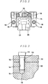
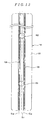
- Fig. 1 is a front elevational view showing a table apparatus comprising a linear guide device having a guide rail 51 and a slider 60, a slider-side member 70 attached to the linear guide device and a substructure 37 as a guide rail-side member to which the linear guide device is attached, which is partly shown as a cross sectional view and also partly shown as a perspective view.
- Fig. 2 is a side elevational view of the linear guide device having the guide rail 51 and the slider 60 of the Fig. 1 as viewed along the direction X.
- Fig. 3 is an enlarged view of portion Y in Fig. 1 viewed from the right side
- Fig. 4 is an enlarged view showing portion Z in Fig. 1 viewed from the right side.
- the table apparatus comprises a linear guide device 50 having the guide rail 51 and the slider 60, the slider-side member 70 and the substructure 37 as the guide rail-side member.
- the slider 60 comprises a slider main body 52, end caps 53 and side seals 54 as main components.
- the constitutions identical with those explained as the prior art carry the same reference numerals, for which explanation is to be omitted.
- the slider main body 52 is attached to the slider-side member 70 with four slider main body attaching screws (retainer bolts) 13.
- the slider main body attaching screw 13 is screwed in the slider main body attaching screw hole 14.
- Fig. 3 shows an enlarged view of the portion Y in Fig. 1, that is, a view of a portion where the slider main body attaching screw 13 is screwed in the screw hole 14 as viewed from the right side in Fig. 1.
- the slider-side member 70 has screw insertion holes 75 and the diameter of the screw insertion hole 75 is slightly larger than the diameter of the retainer bolt (screw 13) which has a hexagon socket head.
- the retainer bolt (screw 13) is allowed to pass therethrough the screw insertion hole 75.
- the slider main body 52 has a screw hole in which the screw 13 is screwed.
- the screw insertion hole 75 and the screw hole of the slider main body 52 comprise a slider main body attaching screw hole 14. Further, a gap 10 is formed as a gas reservoir between the screw insertion hole 75 of the slider-side member 70 and the screw 13.
- a gas reservoir 19 is formed in the lower hole portion of the slider main body attaching screw hole 14.
- a gas vent hole 15 in communication with the gas reservoir 19 is perforated through the slider main body 52.
- the direction of the gas vent hole 15 is substantially in perpendicular to the direction of the slider main body attaching screw hole 14, and the other end of the gas vent hole 15 is open to the outside of the slider main body 52.
- the end caps 53, the side seals 54 and the slider main body 52 are integrally assembled by assembling screws 16 (bolt with a cross recessed head in this embodiment).
- assembling screws 16 are provided on each side of the slider main body 52.
- Screw insertion holes formed in the end cap 53 and the side seal 54, and the screw hole formed in the slider main body 52 comprise an assembling screw hole 17.
- the screw 16 is screwed in the assembling screw hole 17.
- an air vent hole 18 is perforated in the slider main body 52 from the lower hole portion of the assembling screw hole 17.
- the direction of the air vent hole 18 is substantially in perpendicular to the axial direction of the assembling screw hole 17.
- the joining relation between the assembling screw 16 and the assembling screw hole 17 is identical with the joining relation between the slider main body attaching screw 13 and the slider main body attaching screw hole 14 shown in Fig. 3 except for that two members, that is, the end cap 53 and the side seal 54 are present at the portion where the slider-side member 70 exists in Fig. 3.
- the guide rail 51 is secured to the substructure 37 with rail attaching screws 33.
- the rail attaching screw 33 is screwed in a rail attaching screw hole 32.
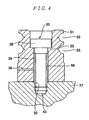
- Fig. 4 shows portion Z of Fig. 1, that is, a portion where the rail attaching screw 33 is screwed in the rail attaching screw hole 32 as viewed from the right side in Fig. 1 in an enlarged scale.
- a head 38 of the rail attaching screw 33 abuts against a counter head 35 of the guide rail 51.
- the guide rail 51 has screw insertion holes 86 and the diameter of the screw insertion hole 86 is slightly larger than the diameter of the retainer bolt (screw 33) which has a hexagon socket head.
- the retainer bolt (screw 33) is allowed to pass therethrough the screw insertion hole 86.
- the substructure 37 has a screw hole in which the screw 33 is screwed.
- the screw insertion hole 86 and the screw hole of the substructure 37 comprise a rail attaching screw hole 32.
- a gap 39 is formed as a gas reservoir between the screw insertion hole 86 of the guide rail 51 and the screw 33.
- a gas reservoir 43 is formed in the lower hole portion of the rail attaching screw hole 32.
- a gas vent hole 36 in communication with the gap 39 is perforated through the guide rail 51.
- the direction of the gas vent hole 36 is substantially in perpendicular to the direction of the rail attaching screw hole 32, and the other end of the gas vent hole 36 is open to the outside of the guide rail 51.
- a linear guide device of this embodiment is different from the linear guide device of the first embodiment in the point, that is, a gas vent hole 71 is perforated from a lower hole portion of a slider main body attaching screw hole 83 to the outside of the slider main body substantially in the axial direction of the slider main body attaching screw hole 83.
- the axis of the gas vent hole 71 is the axis of the screw hole 83 of the slider main body 52 and the lower hole of the screw hole 83, labor over fabrication of the hole to the slider main body 52 can be saved.
- the slider main body attaching screw hole and the gas vent hole can be identical with the constitution shown in Fig. 5, the gas vent hole can be perforated substantially in the axial direction of the slider main body attaching screw hole from the lower hole portion of the slider main body attaching screw hole to the outside of the slider main body, the arranged position of each assembling screw hole can be somewhat shifted from the position shown in Fig. 2 of the first embodiment, and the lower hole of each assembling screw hole can be crossing and be in communication with the lower hole of the slider main body attaching screw hole or the gas vent hole of the slider main body attaching screw hole.
- a linear guide device of this embodiment is different from the linear guide device of the first embodiment in the points, that is, a slider main body attaching pin 40 is used instead of the slider main body attaching screw, and a pin hole 41 is formed in a slider-side member 70 and a slider main body 52 instead of the slider main body attaching screw hole.
- the pin 40 is fitted in the pin hole 41 and then the linear guide device is put in evacuated or depressurized circumstances. Remaining air in the lower hole portion of the pin hole 41 is led to the outside of the slider main body through a gas vent hole 72.
- the guide rail attaching receiving portion can be a hole as shown in Fig. 3, and receiving portion for the slider main body attachment and the receiving portion for assembling can be counter head holes so far as the head of the bolt does not interfere the sliding movement of the slider.
- the table apparatus having the constitution of the first to third embodiments, there is no requirement to use any special screws and usual screws can be used for fixing the end caps and the side seals on the slider main body, for mounting the slider main body with the slider-side member, and for securing the guide rail to the substructure. Further, there is no requirement to form any gas vent holes in the slider-side member and the substructure. As a result, errors can be prevented in the selection of screws for assembling the table apparatus and the number of special parts can be reduced. Further, since there is no requirement to fabricate any vent holes in the slider-side member or the substructure, it is possible to provide a linear guide device or a table apparatus at a reduced cost.
- the gas vent hole is formed from the lower hole portion of the screw hole and the axis of the gas vent hole is the axis of the screw hole, labor over fabrication of the hole such as to the slider main body can be further saved and a linear guide device can be provided at a reduced cost.
- the number of fabrication steps of the slider main body can be decreased further.
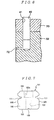
- Fig. 7 shows the fourth embodiment and is an end face view in the longitudinal direction of a guide rail
- Fig. 8 is a bottom view of the guide rail in the fourth embodiment
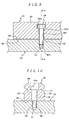
- Fig. 9 is a vertical cross sectional view in a state where the guide rail is secured to a substructure in the fourth embodiment
- Fig. 10 is a cross sectional view taken along line A-A in Fig. 9 with a rail attaching screw being omitted.
- a linear guide device constituting a portion of a table apparatus is shown, and a guide rail 101 constituting a part of the linear guide device has two parallel rolling element grooves 111 on both lateral sides 105 for rolling movement of balls relative to a slider not illustrated, and the slider moves relative to the guide rail 101 with rolling movement of the balls.
- the guide rail 101 is secured to a substructure 130 with rail attaching screws 120.
- a plurality of screw insertion holes 102 are formed and perforating from an upper surface 104 of the guide rail 101 to a seat face 103 formed at the bottom for allowing the rail attaching screws 120 to pass through.
- the screw insertion holes 102 are arranged on a center axial line CLr which is in the longitudinal direction of the guide rail 101.
- Each screw insertion hole 102 has an upper part and a lower part, and the diameter of the upper part is larger and the diameter of the lower part is smaller.
- a step is formed therebetween, and the step constitutes a counter head portion 102a.
- the screw insertion hole 102 and a screw hole 131 of the substructure 130 are combined to form a rail attaching screw hole 150.
- the head of a rail attaching screw 120 is contained in the larger diameter part of the screw insertion hole 102 and seated on the counter head portion 102a. And the shaft portion of the rail attaching screw 120 goes through the smaller diameter part of the screw insertion holes 102.
- the rail attaching screw 120 is screwed in the rail attaching screw hole 150.
- a gap is formed between the screw insertion hole 102 of the guide rail 101 and the rail attaching screw 120, and the gap constitutes a gas reservoir 107a.
- Another gap is formed between the bottom of the screw hole 131 in the substructure 130 and the top end of the rail attaching screw 120, and this gap constitutes a gas reservoir 107b.
- Orifices of the screw insertion holes 102 are arranged along the central axial line CLr in the longitudinal direction of the guide rail 101 on the seat surface 103 of the guide rail 101.
- a groove 109 with a trapezoidal cross sectional shape is formed on the seat surface 103.
- the groove 109 is continuous from one end face 106 to the other end face 106 of the guide rail 101 in the lateral central portion of the seat surface 103, and connects the orifices of the screw insertion holes 102 on the seat surface 103 successively.
- the condition in the gas reservoir 107b is also evacuated or depressurized.
- each groove 109 can be formed on the seat surface 103.
- the center axis CLg of each of the two grooves 109 is in contact with circles formed by the screw insertion hole 102 on the seat surface 103.
- each screw insertion hole 102 is in communication with both of the grooves 109.
- each groove 109 can be formed at the position which is nearer to the central axis CLr of the guide rail 101 than the position shown in Fig. 11 and Fig. 12. And in this position, the central axis CLg of each groove 109 is intersected with the circle formed by the screw insertion hole 102 on the seat surface 103.
- the cross sectional shape of the groove 109 can be formed in an arcuate shape, a trigonal shape or a polygonal shape.
- Fig. 16 shows a fifth embodiment and is an end view of a guide rail.
- a communication channel 110 is added to the guide rail 101 shown in Fig. 7 to Fig. 10 of the fourth embodiment.
- identical constitutions with those of the fourth embodiment of the invention carry the same reference numerals for which duplicate explanation will be omitted.
- a communication channel 110 is formed on the end face 106 of the guide rail 101, and comprises a groove with an identical cross section to the cross section of the groove 109.
- the communication channel 110 is a linear groove which is continuous from the end of the groove 109 on the seat surface 103 to the upper surface 104, and is in communication with the groove 109 at the corner between the seat surface 103 and the end face 106.
- the condition in the communication channel 110 is also evacuated or depressurized.
- the condition in the groove 109 is also evacuated or depressurized. Accordingly, the condition in the gas reservoirs 107a and 107b is also evacuated or depressurized like the fourth embodiment.
- the communication channel 110 on the end face 106 can be formed by connecting the end of the groove 109 formed on the seat surface 103 of the guide rail 101 with one or both of lateral surfaces 105 or rolling element grooves 111. Further, it is also possible to form a hole as the communication channel 110. The hole perforates through the inside of the guide rail, and is in communication with the groove 109. The hole is connected with at least one of the upper surface 104, lateral surface 105 or the rolling element grooves 111.
- the position of the hole can be arranged irrelevant to the position of the screw insertion holes 102, the degree of freedom to arrange the position of the hole which perforates through the guide rail is increased.
- the cross sectional shape of the communication channel 110 on the end face 106 can be formed in an arcuate shape, a trigonal shape or a polytonal shape.
- the guide rail 101 is secured to the upper surface of the substructure 130, they can be turned up side down and the guide rail 101 is secured to the lower surface of the substructure 130.
- the linear guide device comprising the guide rail 101 according to the fourth and fifth embodiments can provide the same effects as those in the first to third embodiments. Further, it is not necessary to form any gas vent holes individually to each of the screw insertion holes 102 of the guide rail 101 and the screw holes 131 of the substructure 130 as in the first to third embodiments, and the groove 109 on the seat surface 103 can be formed while the guide rail 101 is drawn in its fabrication process or the seat surface 103 of the guide rail 101 is ground in its fabrication process. This can provide an effect capable of manufacturing a linear guide device rapidly and in cost-reduced steps. Further, by forming the groove 109 on the seat surface 103 before forming the rolling element grooves, the fabrication step of the groove 109 gives no undesired effects on the accuracy of the linear guide device.
- Fig. 18 is a front elevation view of a slider device according to the sixth embodiment
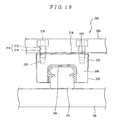
- Fig. 19 is a side elevational view of the slider device according to the sixth embodiment as viewed in the longitudinal direction of a guide rail
- Fig. 20 is an upper plan view of a slider according to the sixth embodiment
- Fig. 21 is a partly cross sectioned side elevational view of the slider according to the sixth embodiment as viewed in the longitudinal direction of the guide rail.
- a linear guide device comprises a slider 200 and a guide rail 101.
- a table apparatus 290 comprises the linear guide device, a slider-side member 250 and a substructure 130 as a guide rail-side member.
- the substructure 130 and the guide rail 101 have the same constitution as the substructure and the guide rail according to the fourth embodiment, which carry identical reference numerals and for which explanation is to be omitted.
- the slider-side member 250 is of a plate shape with both the surface and the rear face being planar, in which screw insertion holes 213 are formed, and the screw insertion holes 213 perforate through the slider side member 250 from the surface to the rear face are formed.
- the slider 200 comprises a slider main body 202, end caps 204 and side seals 206.
- the upper surface 208 of the slider main body 202 is of a substantially rectangular shape and faces in the same direction as the upper surface 104 of the guide rail 101.
- the upper surface 210 of the end cap 204 and the upper surface 212 of the side seal 206 also face in the same direction as the upper surface 104 in the same manner.
- the upper surfaces 208, 210 and 212 constitute the upper surface of the slider 200.
- the upper surface 210 and the upper surface 212 are on one identical plane, and the upper surface 208 constitutes a protruding surface from the upper surface 210 by a step.
- screw holes 214 are open respectively at four corners on the diagonal lines of the rectangular shape of the upper surface 208 (refer to Fig. 20). And one screw insertion hole 213 and one screw hole 214 are combined to form a slider main body attaching screw hole 215 (refer to Fig. 18 and Fig. 19). Then, the attaching screws 216 are screwed in the attaching screw holes 215 and the slider-side member 250 is secured to the upper surface 208 of the slider main body 202.
- two parallel escape grooves 218 are formed on the upper surface 208.
- Each of the escape grooves 218 is in parallel with the central axis CLr of the guide rail 101, and extends from one edge to the opposite edge of the upper surface 208.
- the escape grooves 218 serve to reduce the grinding resistance.
- two grooves 220 are formed in parallel with the escape grooves 218 respectively.
- Each of the grooves 220 has a square cross sectional shape (refer to Fig. 21) and, like the escape groove 218, each of the grooves 220 extends from one edge to the opposite edge of the upper surface 208.
- One of the grooves 220 connects orifices of the two screw holes 214 on one side of the central axis CLr of the guide rail 101 on the upper surface 208. And orifices of other two screw holes 214 are also connected by the other groove 220. Since other constitutions of the slider 200 are identical with those of the existent slider, explanation therefor will be omitted.
- the attaching screws 216 are screwed in the attaching screw holes 215, and the slider-side member 250 is secured to the upper surface 208 of the slider main body 202.
- the rear face of the slider-side member 250 is in contact with the upper surface 208, but the inner surfaces of the groove 220 and the escape groove 218 are not in contact with the rear face of the slider-side member 250.
- the inner sides of the groove 220 and the escape groove 218 constitute spaces respectively, and each end of the groove 220 and the escape groove 218 is open to the outside of the table apparatus at the edge of a portion where the upper surface 208 and the rear face of the slider-side member 250 are in contact with each other (refer to Fig. 18 and Fig. 19).
- a gas reservoir 232 is formed between the attaching screw hole 215 and the attaching screw 216.
- the effect of the groove 220 on the remaining air in the gas reservoir 232 is identical with the effect of the groove 109 in the fourth embodiment on the remaining air in the gas reservoirs 107a and 107b. That is, when the table apparatus 290 with the linear guide device is put under evacuated or depressurized circumstances, the condition in the groove 220 which is in communication with the outside of the table apparatus 290 with the linear guide device is also evacuated or depressurized. And the condition in the gas reservoir 232 which is in communication with the groove 220 is also evacuated or depressurized. Accordingly, the condition in the gas reservoir 232 is evacuated or depressurized in a short period of time.
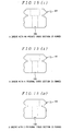
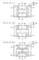
- the cross sectional shape of the groove 220 is formed in rectangular shape, but it can be of an arcuate shape as shown in (i) of Fig. 22, a trigonal shape as sown in (ii) of the figure, a polygonal shape as shown in (iii) of the figure or the like.
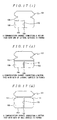
- the grooves 220 are formed in parallel with the escape grooves 218, but, as shown in (i) of Fig. 23, on the upper surface 208 of the slider main body 202, the grooves 220 can be formed such that the grooves 220 cross at a right angle with the escape grooves 218 to connect screw holes 214. Further, as shown in (ii) of the figure, the grooves 220 can be formed on the upper surface 208 between the escape groove 218 and one edge of the upper surface 208. Further, as shown in (iii) of the figure, the grooves 220 can also be formed such that they are substantially aligned with the diagonal lines of the square forming the upper surface 208.
- the linear guide device or the table apparatus with the slider main body 202 according to the sixth embodiment can provide the same effects as the first to third embodiments. Furthermore, it is not required to form any gas vent holes to the slider main body 202 and the slider-side member 250 individually. And the grooves 220 can be formed when the upper surface 208 of the slider main body 202 is ground. Therefore the linear guide device can be manufactured with rapid and inexpensive steps.
- the groove 109 is in contiguous from one end face to the other end face of the guide rail 101, as well as another example in which the groove 220 is in contiguous from one end face (lateral surface) to the other end face (lateral surface) of the slider main body 202 so as to pass two screw holes 214.
- the groove 109 or the groove 220 in communication with the outer surface of the guide rail 101 or the slider main body 202 can be formed each by one on every screw insertion hole 102 or screw hole 214 respectively.
- Fig. 24 is a fragmentary longitudinal cross sectional view of a slider according to the seventh embodiment
- Fig. 25 is an upper plan view of a washer according to the seventh embodiment.
- a table apparatus has the same constitution as that in the existent table apparatus in which a slider main body 352 and a plate-like slider-side member 370 constitute a portion of the table apparatus.
- a screw hole 384 is formed to the slider main body 352
- a screw insertion hole 387 is formed to the slider-side member 370.
- the screw hole 384 and the screw insertion hole 387 are combined to form an attaching screw hole 388.
- a counter head 387a is formed in the screw insertion hole 387.
- an attaching screw 321 is screwed in the attaching screw hole 388 and the slider-side member 370 is secured to the slider main body 352 with the attaching screw 321. Further, the lower surface 322 of the head of the attaching screw 321 is seated on the counter head 387a. Further, a gas reservoir 324 is formed in a gap between the attaching screw 321 and the attaching screw hole 388.
- a washer 330 is interposed between the lower surface 322 of the head of the attaching screw 321 and the counter head 387a.
- the washer 300 has the same constitution as the existent spring washer that is interposed between clamping surfaces of a bolt and a nut. That is, the washer 330 has a ring-shape with a hole at the center of the ring, and a screw shaft of the attaching screw 321 goes through the hole. And the washer 330 has a gap which cuts the circumference of the ring. The gap forms a channel 331. At the center of the ring of the washer 330, the diameter of the hole is larger than the diameter of the screw shaft of the attaching shaft 321 and smaller than the diameter of the head of the attaching screw 321.
- the washer 330 is put and secured between the lower surface 322 of the head of the attaching screw 321 and the counter head 387a of the screw insertion hole 387.
- the channel 331 links the outside of the washer 330 to the hole at the center of the ring.
- the end of the channel 331 at the hole side of the ring of the washer 330 situates just above the gap between the attaching screw 321 and the screw insertion hole 387. Accordingly, the gas reservoir 324 is in communication with the outside of the table apparatus through the channel 331.
- the washer 330 of this embodiment can be applied to a screw hole formed in any of the members constituting the table apparatus and a screw which is screwed in the screw hole.
- the washer 330 is a spring washer with a gap
- it can be a flat washer with a gap instead of the spring washer.
- the gap instead of the gap, it can be a groove or a hole which links the inner side to the outer, the groove is formed to at least one of the surface or the rear face of the washer, and the hole perforates through the washer.
- the present invention provides a guide rail for the linear guide device as described above, it provides the following effects. That is, it can provide a linear guide device suitable to be used in an evacuated or depressurized circumstances without using any special screws formed with a gas vent hole, as well as a table apparatus with the linear guide device described above.
Landscapes
- Engineering & Computer Science (AREA)
- General Engineering & Computer Science (AREA)
- Mechanical Engineering (AREA)
- Bearings For Parts Moving Linearly (AREA)
- Magnetic Bearings And Hydrostatic Bearings (AREA)
Abstract
Description
Claims (7)
- A table apparatus in which a joining member for joining a predetermined combination for a plurality of members constituting a table apparatus comprising a guide rail, a slider, a guide rail-side member to which the guide rail is attached and a slider-side member to which the slider is attached, and a receiving portion for receiving the joining member are disposed to the members comprising the combination described above, wherein
a channel that is in communication from a gap formed between the joining member and the receiving portion by receiving the joining member in the receiving portion to the outside of the table apparatus is formed to at least one of the members that constitute the table apparatus. - A table apparatus as defined in claim 1, wherein the channel is a gas vent hole that perforates through at least one of the members constituting the table apparatus.
- A table apparatus as defined in claim 1, wherein the channel is a groove formed on the surface of the member constituting the table apparatus.
- A table apparatus as defined in claim 3, wherein the receiving portion is a receiving portion with which the slider and the slider-side member are combined and joined to each other, that is, a plurality of attaching screw holes that open on each of the surfaces of the slider and the slider-side member combined and opposed to each other,
the groove is formed on at least one of the surfaces of the slider and the slide side member opposed to each other, and
the groove is in contiguous from the opening of the attaching screw hole to the end of a portion where the opposing surfaces are in contact with each other. - A table apparatus as defined in claim 3, wherein the receiving portion is a receiving portion with which the guide rail and the guide rail-side member are joined, that is, a plurality of attaching screw holes that open on each of the surfaces of the guide rail and the guide rail-side member combined and opposed to each other,
the groove is formed on at least one of the surfaces of the guide rail and the guide rail-side member combined and opposed to each other, and
the groove is in contiguous from the opening of the attaching screw hole to the end of a portion where the opposing surfaces are in contact with each other. - A table apparatus as defined in claim 4 or 5, wherein the groove has a communication channel that is in communication to a surface of the member in which the groove is formed and the surface is one of the surfaces on which the groove is not formed.
- A table apparatus in which a joining member for joining a predetermined combination for a plurality of members constituting a table apparatus comprising a guide rail, a slider, a guide rail-side member to which the guide rail is attached and a slider-side member to which the slider is attached, and a receiving portion for receiving the joining member are disposed to the members comprising the combination described above, wherein
the joining member comprises an attaching screw and the receiving portion comprises an attaching screw hole,
the attaching screw is screwed in the attaching screw hole with a washer being interposed between the head of the attaching screw and the attaching screw hole, and
the washer has a channel that is in communication from a gap formed between the attaching screw and the attaching screw hole to the outside of the table apparatus.
Applications Claiming Priority (3)
| Application Number | Priority Date | Filing Date | Title |
|---|---|---|---|
| JP2001144787 | 2001-05-15 | ||
| JP2001144787 | 2001-05-15 | ||
| PCT/JP2002/003874 WO2002093031A1 (en) | 2001-05-15 | 2002-04-18 | Table device |
Publications (3)
| Publication Number | Publication Date |
|---|---|
| EP1394427A1 true EP1394427A1 (en) | 2004-03-03 |
| EP1394427A4 EP1394427A4 (en) | 2009-12-16 |
| EP1394427B1 EP1394427B1 (en) | 2012-04-11 |
Family
ID=18990688
Family Applications (1)
| Application Number | Title | Priority Date | Filing Date |
|---|---|---|---|
| EP02720496A Expired - Lifetime EP1394427B1 (en) | 2001-05-15 | 2002-04-18 | Table device |
Country Status (3)
| Country | Link |
|---|---|
| EP (1) | EP1394427B1 (en) |
| JP (1) | JPWO2002093031A1 (en) |
| WO (1) | WO2002093031A1 (en) |
Cited By (1)
| Publication number | Priority date | Publication date | Assignee | Title |
|---|---|---|---|---|
| DE102005029854A1 (en) * | 2005-06-27 | 2007-01-04 | P & L Gmbh & Co. Kg | Linear guide rail for a linear guide system |
Family Cites Families (14)
| Publication number | Priority date | Publication date | Assignee | Title |
|---|---|---|---|---|
| JPS56131010U (en) * | 1980-03-07 | 1981-10-05 | ||
| JPS6029923U (en) | 1983-08-05 | 1985-02-28 | 寺町 博 | Track base for linear sliding bearings |
| JPS6357908A (en) * | 1986-08-29 | 1988-03-12 | 株式会社安川電機 | Air vent method in clamping device in vacuum |
| JPH01118212U (en) * | 1988-02-03 | 1989-08-10 | ||
| JP2529952Y2 (en) * | 1990-08-27 | 1997-03-26 | 日本トムソン株式会社 | Linear motion rolling guide unit |
| JP2544027Y2 (en) * | 1991-03-18 | 1997-08-13 | 日本トムソン株式会社 | Finite linear motion rolling guide unit |
| JPH0654908U (en) * | 1993-01-05 | 1994-07-26 | 日本バルカー工業株式会社 | Vacuum bolt |
| JP3209472B2 (en) * | 1993-11-05 | 2001-09-17 | 東京エレクトロン株式会社 | Screw cap and processing equipment |
| JP3547209B2 (en) * | 1995-03-08 | 2004-07-28 | 日本トムソン株式会社 | Linear motion rolling guide unit |
| JPH10325414A (en) * | 1997-03-25 | 1998-12-08 | Nippon Seiko Kk | Linear motion device |
| JP2000014124A (en) * | 1998-06-26 | 2000-01-14 | Toshiba Corp | Vacuum part connection structure |
| JP4298818B2 (en) * | 1998-08-18 | 2009-07-22 | Thk株式会社 | Linear rolling guide device |
| DE10114619B4 (en) * | 2000-03-27 | 2006-07-27 | Cummins Inc., Columbus | Ventilating fastening element |
| JP2002122135A (en) * | 2000-08-11 | 2002-04-26 | Nsk Ltd | Linear guide device |
-
2002
- 2002-04-18 EP EP02720496A patent/EP1394427B1/en not_active Expired - Lifetime
- 2002-04-18 JP JP2002590267A patent/JPWO2002093031A1/en active Pending
- 2002-04-18 WO PCT/JP2002/003874 patent/WO2002093031A1/en not_active Ceased
Cited By (2)
| Publication number | Priority date | Publication date | Assignee | Title |
|---|---|---|---|---|
| DE102005029854A1 (en) * | 2005-06-27 | 2007-01-04 | P & L Gmbh & Co. Kg | Linear guide rail for a linear guide system |
| DE102005029854B4 (en) * | 2005-06-27 | 2009-04-16 | P & L Gmbh & Co. Kg | Linear guide rail for a linear guide system |
Also Published As
| Publication number | Publication date |
|---|---|
| JPWO2002093031A1 (en) | 2004-09-02 |
| EP1394427A4 (en) | 2009-12-16 |
| EP1394427B1 (en) | 2012-04-11 |
| WO2002093031A1 (en) | 2002-11-21 |
Similar Documents
| Publication | Publication Date | Title |
|---|---|---|
| US8764293B2 (en) | Linear guide apparatus | |
| DE112017004831T5 (en) | VALVE DEVICE | |
| EP0608528B1 (en) | Vacuum table | |
| KR20090102713A (en) | Hydraulic damper | |
| US7306372B2 (en) | Table device | |
| US20190250645A1 (en) | Motor-operated valve | |
| EP1450431A1 (en) | Fuel cell assembly | |
| US8042573B2 (en) | Fluid control device | |
| EP1394427B1 (en) | Table device | |
| DE20020236U1 (en) | Alternative compressor of a hermetic cooling unit with an improved valve system | |
| WO2006103279A9 (en) | Refrigeration compressor | |
| DE102010017983B4 (en) | Oil sight glass with elastomers | |
| US20050023496A1 (en) | Deformed o-ring face seal for pneumatic valves | |
| DE19529684C2 (en) | Piston compressors, in particular for the generation of compressed air in motor vehicles | |
| EP2842714A2 (en) | Pressure equalising element | |
| KR200404835Y1 (en) | The pick up cylinder for element of a semiconductor | |
| US6481334B1 (en) | Rodless cylinder | |
| DE102008037672B4 (en) | Piston compressor, in particular refrigerant compressor | |
| US20090152189A1 (en) | Laterally sealing gasket interface | |
| US20060255547A1 (en) | Zip strip seal | |
| EP1389711B1 (en) | Recessed lighting fixture | |
| DE3631463C2 (en) | Pressure retention valve | |
| EP3162974B1 (en) | Ceiling system | |
| KR102542680B1 (en) | Ball screw | |
| US6557649B1 (en) | Pneumatic tool structure |
Legal Events
| Date | Code | Title | Description |
|---|---|---|---|
| PUAI | Public reference made under article 153(3) epc to a published international application that has entered the european phase |
Free format text: ORIGINAL CODE: 0009012 |
|
| 17P | Request for examination filed |
Effective date: 20031125 |
|
| AK | Designated contracting states |
Kind code of ref document: A1 Designated state(s): AT BE CH CY DE DK ES FI FR GB GR IE IT LI LU MC NL PT SE TR |
|
| A4 | Supplementary search report drawn up and despatched |
Effective date: 20091118 |
|
| RIC1 | Information provided on ipc code assigned before grant |
Ipc: F16B 35/00 20060101ALI20091112BHEP Ipc: F16C 29/00 20060101AFI20021125BHEP |
|
| 17Q | First examination report despatched |
Effective date: 20100331 |
|
| RIC1 | Information provided on ipc code assigned before grant |
Ipc: F16B 35/00 20060101ALI20110324BHEP Ipc: F16C 29/00 20060101AFI20110324BHEP |
|
| GRAP | Despatch of communication of intention to grant a patent |
Free format text: ORIGINAL CODE: EPIDOSNIGR1 |
|
| GRAS | Grant fee paid |
Free format text: ORIGINAL CODE: EPIDOSNIGR3 |
|
| GRAA | (expected) grant |
Free format text: ORIGINAL CODE: 0009210 |
|
| RIN1 | Information on inventor provided before grant (corrected) |
Inventor name: NAKAMURA, TSUYOSHI,C/O NSK LTD. Inventor name: TAJIMI, HIDEYUKI,C/O NSK LTD. Inventor name: SAJI, NOBUHITO,C/O NSK LTD. |
|
| AK | Designated contracting states |
Kind code of ref document: B1 Designated state(s): DE GB |
|
| REG | Reference to a national code |
Ref country code: GB Ref legal event code: FG4D |
|
| REG | Reference to a national code |
Ref country code: DE Ref legal event code: R096 Ref document number: 60242625 Country of ref document: DE Effective date: 20120606 |
|
| PLBE | No opposition filed within time limit |
Free format text: ORIGINAL CODE: 0009261 |
|
| STAA | Information on the status of an ep patent application or granted ep patent |
Free format text: STATUS: NO OPPOSITION FILED WITHIN TIME LIMIT |
|
| 26N | No opposition filed |
Effective date: 20130114 |
|
| GBPC | Gb: european patent ceased through non-payment of renewal fee |
Effective date: 20120711 |
|
| PG25 | Lapsed in a contracting state [announced via postgrant information from national office to epo] |
Ref country code: GB Free format text: LAPSE BECAUSE OF NON-PAYMENT OF DUE FEES Effective date: 20120711 |
|
| REG | Reference to a national code |
Ref country code: DE Ref legal event code: R097 Ref document number: 60242625 Country of ref document: DE Effective date: 20130114 |
|
| PGFP | Annual fee paid to national office [announced via postgrant information from national office to epo] |
Ref country code: DE Payment date: 20190402 Year of fee payment: 18 |
|
| REG | Reference to a national code |
Ref country code: DE Ref legal event code: R119 Ref document number: 60242625 Country of ref document: DE |
|
| PG25 | Lapsed in a contracting state [announced via postgrant information from national office to epo] |
Ref country code: DE Free format text: LAPSE BECAUSE OF NON-PAYMENT OF DUE FEES Effective date: 20201103 |