EP1394368A2 - A Hydraulic Damper for an Electromechanical Valve - Google Patents
A Hydraulic Damper for an Electromechanical Valve Download PDFInfo
- Publication number
- EP1394368A2 EP1394368A2 EP03102545A EP03102545A EP1394368A2 EP 1394368 A2 EP1394368 A2 EP 1394368A2 EP 03102545 A EP03102545 A EP 03102545A EP 03102545 A EP03102545 A EP 03102545A EP 1394368 A2 EP1394368 A2 EP 1394368A2
- Authority
- EP
- European Patent Office
- Prior art keywords
- opening
- piston
- chamber
- damper
- chamber portion
- Prior art date
- Legal status (The legal status is an assumption and is not a legal conclusion. Google has not performed a legal analysis and makes no representation as to the accuracy of the status listed.)
- Granted
Links
Images

Classifications
-
- F—MECHANICAL ENGINEERING; LIGHTING; HEATING; WEAPONS; BLASTING
- F01—MACHINES OR ENGINES IN GENERAL; ENGINE PLANTS IN GENERAL; STEAM ENGINES
- F01L—CYCLICALLY OPERATING VALVES FOR MACHINES OR ENGINES
- F01L9/00—Valve-gear or valve arrangements actuated non-mechanically
- F01L9/20—Valve-gear or valve arrangements actuated non-mechanically by electric means
-
- F—MECHANICAL ENGINEERING; LIGHTING; HEATING; WEAPONS; BLASTING
- F01—MACHINES OR ENGINES IN GENERAL; ENGINE PLANTS IN GENERAL; STEAM ENGINES
- F01L—CYCLICALLY OPERATING VALVES FOR MACHINES OR ENGINES
- F01L9/00—Valve-gear or valve arrangements actuated non-mechanically
- F01L9/20—Valve-gear or valve arrangements actuated non-mechanically by electric means
- F01L9/21—Valve-gear or valve arrangements actuated non-mechanically by electric means actuated by solenoids
- F01L2009/2151—Damping means
Definitions
- the invention relates to a hydraulic damper for an electromechanical valve and in particular to a hydraulic damper that can provide relatively soft seating of an engine valve on an engine valve seat.
- electromechanical valves use first and second solenoids to induce an inner armature to move in first and second axial directions, respectively.
- the armature may be coupled to a valve member that opens and closes a respective port to an engine cylinder.
- a problem associated with known electromechanical valves is that it is extremely difficult to control the landing speed (i.e., the seating speed) of a valve head against a valve seat. If the landing speed is too high, the engine valve seat can become degraded.
- a known system in U.S. Patent No. 5,832,883 utilized a hydraulic damper for reducing the seating speed in an electromechanical valve assembly.
- a piston is disposed in a chamber filled with oil.
- the piston is connected to a valve member and separates the chamber into an upper portion and a lower portion.
- the piston also contains a constant area orifice extending therethrough.
- the first and second chamber portions are also connected by a conduit.
- fluid is pushed through the conduit (and the constant area orifice) from the first chamber portion to the second chamber portion.
- the constant area orifice continues to allow fluid to pass from the first chamber portion to the second chamber portion.
- the fluid flow through the constant area orifice prevents the damping pressure in the first chamber from reaching a relatively high pressure. Further, the reduced damping pressure in the first chamber portion can result in the valve member connected to the damper piston having a relatively high seating speed when it contacts the valve seat. As discussed above, the relatively high landing speed may undesirably degrade the valve seat and valve member.
- a hydraulic damper for an electromechanical valve assembly having a valve member characterised in that the hydraulic damper comprises a housing defining a chamber for holding fluid extending along an axis, a damper stem disposed in the chamber configured to move along the axis and configured to be directly coupled to the valve member; and a piston coupled to the damper stem dividing the chamber into a first chamber portion and a second chamber portion, the housing having a conduit extending between the first chamber portion and the second chamber portion, the conduit having a first opening communicating with the first chamber portion wherein when the piston moves past at least a portion of the opening, the cross-sectional area of the opening decreases restricting fluid flow from the first chamber to reduce a velocity of the piston.
- the effective cross-sectional area of the opening may decrease substantially linearly when the piston moves past a portion of the first opening.
- the piston displaces fluid from the first chamber portion through the conduit to the second chamber portion until the piston closes off the first opening of the conduit.
- the conduit may have a second opening communicating with the second chamber portion which may be a non-cylindrical opening.
- the first opening is a non-cylindrical opening
- the piston may have no bypass orifices extending therethrough allowing fluid communication between the first chamber portion and the second chamber portion.
- the first opening of the conduit may include a tapered portion communicating with the first chamber portion.
- the effective cross-sectional area of the first opening may decrease substantially linearly when the piston moves past the tapered portion of the first opening.
- the second opening of the conduit may include a tapered portion communicating with the second chamber portion.
- the effective cross-sectional area of the second opening may decrease substantially linearly when the piston moves past the tapered portion of the second opening.
- Both of the openings may have a tapering portion.
- the housing may be configured to be mounted to the electromechanical valve.
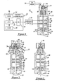
- FIG. 1 shows a vehicle 10 having an engine control system 12, an engine 14, and an oil pump 16.
- the engine 14 includes an electromechanical valve assembly 18 mounted to an engine head 20 which includes an electromechanical actuator 21 and a hydraulic damper 22 in accordance with the present invention.
- Engine control system 12 includes engine controller 24 and current driver 26.
- Controller 24 generates control signals to control an operational position of a valve member 28 of valve assembly 18.
- the current driver 26 receives the control signals from controller 24 and in response generates current signals to energize and de-energize coils 30, 32 of actuator 21 to control the position of valve member 28, as will be explained in greater detail below.
- controller 24 includes a central processing unit (CPU) 34, a read only memory (ROM) 36, a random access memory (RAM) 38, and input/output (I/O) ports 40.
- CPU central processing unit
- ROM read only memory
- RAM random access memory
- I/O input/output
- electromechanical valve assembly 18 includes electromechanical actuator 21 and damper 22.
- An actuator 21 is provided to control gas flow through a port 42 communicating with an engine cylinder (not shown).
- the actuator 21 can be disposed in an intake port or an exhaust port communicating with the engine cylinder and controls an axial position of valve member 28 to control gas flow through port 42.
- actuator 21 includes actuator housing 44, valve member 28, coils 30, 32, armature plate 46 and spring retainer plate 48 attached to member 28, and springs 50, 52, 54, 56.
- housing 44 encloses the remaining of the actuator components and may be mounted to engine head 20 via conventional fasteners (not shown).
- valve member 28 when coil 32 is de-energized by controller 24, springs 54, 56 induces valve member 28 to move upwardly so that a valve head 58 approaches valve seat 60.
- coil 30 is energized causing armature plate 46 to move toward coil 30 which in turn causes valve head 60 to be seated against a valve seat 60 in fully closed position.
- the closed position of valve member 58 is illustrated in Figure 1.
- gas flow through port 42 is prevented from either entering or exiting an engine cylinder (not shown).
- valve member 28 When the coil 30 is de-energized, springs 50, 52 induce valve member 28 to move downwardly so that valve head 58 moves away from valve seat 60. During this movement, coil 32 is energized which causes armature plate 46 to be attracted toward coil 32 and valve head 58 to be moved to a fully open position. The fully open position is illustrated in Figure 3. Thus, gas flow through port is allowed to enter or exit an engine cylinder through port 42.
- hydraulic damper 22 in accordance with the present invention is provided to allow relatively soft seating of valve head 58 on valve seat 60.
- Damper 22 includes a housing 62, a damper stem 64, a piston 66, a retaining nut 68, and a washer 70.
- Housing 62 is provided to form a chamber 72 for holding a damping fluid such as engine oil.
- Chamber 72 comprises a top plate 74, a body portion 76, and a side plate 78.
- the top plate 74 and the side plate 78 may be attached to body portion 76 via conventional fasteners (not shown) to form chamber 72.
- the top plate 74 has a bore 79 extending therethrough for communicating oil from engine oil pump 16 to chamber 72.
- the pump 16 provides lubrication oil to several engine components, like bearings for example, and the oil that would normally be provided to an engine camshaft is now delivered to chamber 72, at the same pressure that is required by the other engine components.
- Lubrication pressure is typically regulated between 68kPA and 551kPA (10 and 80 P.S.I.)
- Body portion 76 includes a bottom plate 80 and annular attachment portion 82 axially extending from plate 80 that may be attached to a receiving portion 84 of housing 62.
- attachment portion 82 may have external threads (not shown) that couple to threads disposed on an internal surface of receiving portion 84 of actuator 21.
- Damper stem 64 extends along an axis 86 through chamber 72 of housing 62 and is coupled to a valve stem 90 of valve member 28.
- damper stem 64 may have an internal threaded bore 88 that threadably receives one end of valve stem 90.
- valve stem 90 and damper stem 64 are coupled together and move in unison in first and second axial directions.
- Piston 66 is coupled around damper stem 64 between a washer 70 and a retainer nut 68. Piston 66 is provided to divide chamber 72 into a chamber portion 92 above the piston 66 and a chamber portion 94 below the piston 66. Housing 62 also includes a conduit 96 which extends between chamber portions 92, 94.
- fluid in portion 92 is moved through conduit 96 to portion 94. Because the fluid must travel through the conduit 96 before entering the chamber portion 92, a pressure differential occurs where the pressure in portion 92 is lower than the pressure in portion 94. This pressure differential between the chamber portions 92, 94 produces a damping force in portion 94 opposing motion in a second axial direction (downward direction in Figure 2).
- the piston 66 begins to close off an opening 100 of conduit 96, fluid flow is further restricted from chamber portion 92 to portion 94. This fluid restriction increases the damping force in chamber portion 94 which further reduces the velocity of piston 66, damper stem 64 and valve member 28 which will be described in greater detail below.
- conduit 96 includes valve openings 98, 100 communicating with chamber portions 92, 94. Because openings 98, 100 can have a similar shape and operating characteristic, only opening 98 will be discussed in detail. As shown, opening 98 includes first and second opening portions 102, 104. The second opening portion 104 tapers over a predetermined distance, such as 1 mm for example, to provide an increasing damping force in chamber 92 prior to valve seating.
- the portion 104 can also be configured to provide a linear or non-linear decrease in the velocity of valve member 28 as it approaches a seating position.
- the portion 104 shown in Figure 104 provides a substantially linear decrease in the velocity of valve member 28 as it approaches the seating position against valve seat 60.
- the taper angle ( ⁇ ) and axial distance (D) of second opening portion 104 can be varied based upon a desired velocity profile prior to and during valve seating.
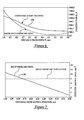
- a graph of the effective area of the second opening portion 104 is shown during the last 1mm of travel of piston 66, damper stem 64, and valve member 28 before valve seating occurs.
- the curve 106 illustrates that the effective cross-sectional area of opening portion 104 decreasing substantially linearly toward a zero effective area as piston 66 approaches the seating position (SP) where valve head 58 is seated against valve seat 60.
- a graph of the damping force generated in chamber portion 92 during the last 1mm of travel of damper stem 64 and valve member 28 is shown.
- the damping force in chamber portion 92 is maintained at over 280 Newtons, for example, prior to valve seating.
- This damping force causes the velocity of piston 66, damper stem 64, and valve member 28, shown by curve 110 in Figure 5, to smoothly approach 0 m/s during valve seating.
- the inventive damper system provides a substantial advantage over known systems, such as the constant area orifice system described in U.S. Patent No. 5, 832,883.
- the curve 112 represents the response of the conventional constant area orifice, assuming a piston size of 20 mm, during the final 1 mm of travel prior to valve seating.
- the velocity of the conventional system is approximately 0.8 m/s just prior to valve seating - --as compared to a seating velocity of 0.1 m/s of the inventive damping system 22.
- the inventive damper 22 substantially reduces the velocity of valve member 28 as compared to the conventional system.
- the damping force in chamber portion 92 is maintained at approximately 280 N just prior to valve seating as compared to 180 N of damping force generated by the known system. Accordingly, the inventive system maintains a greater damping force prior to valve seating for a given piston diameter, as compared to the known systems.
- the piston size of the damper can be reduced as compared to known systems for a desired damping force which reduces the reciprocating mass of the electromechanical valve and undesirable mid-travel drag and friction forces acting on the damper piston.
- overall power consumption of an electromechanical valve assembly is reduced.
- the hydraulic system in accordance with the present invention therefore provides a substantial advantage over known systems by providing a conduit having a non-cylindrical opening that is used to control a damping force prior to and during valve seating to dramatically reduce a seating velocity.
- damper stem of the damper can be directly coupled to an engine valve member to remove any undesirable contact noise between a valve member and a component of the damper.
Landscapes
- Engineering & Computer Science (AREA)
- Mechanical Engineering (AREA)
- General Engineering & Computer Science (AREA)
- Magnetically Actuated Valves (AREA)
- Valve Device For Special Equipments (AREA)
- Fluid-Damping Devices (AREA)
Abstract
Description
Claims (10)
- A hydraulic damper (22) for an electromechanical valve assembly (18)having a valve member (28) characterised in that the hydraulic damper (22) comprises a housing (62) defining a chamber (72) for holding fluid extending along an axis, a damper stem (64) disposed in the chamber (72) configured to move along the axis and configured to be directly coupled to the valve member (28) and a piston (66) coupled to the damper stem (64)dividing the chamber (72) into a first chamber portion (92) and a second chamber portion (94), the housing (62) having a conduit (96) extending between the first chamber portion (92) and the second chamber portion (94), the conduit (96) having a first opening (98) communicating with the first chamber portion (92) wherein when the piston (66) moves past at least a portion of the opening (98), the cross-sectional area of the opening (98) decreases restricting fluid flow from the first chamber (92) to reduce a velocity of the piston (66).
- A hydraulic damper as claimed in claim 1 wherein the effective cross-sectional area of the opening (98) decreases substantially linearly when the piston (66) moves past a portion of the first opening (98).
- A hydraulic damper in claim 1 or in claim 2 wherein when the damper stem (64) is moved in a first axial direction the piston (66) displaces fluid from the first chamber portion (92) through the conduit (96) to the second chamber portion (94) until the piston (66) closes off the first opening (98) of the conduit (96).
- A hydraulic damper as claimed in any of claims 1 to 3 wherein the conduit (96) has a second opening (100) communicating with the second chamber portion (94).
- A hydraulic damper as claimed in claim 4 wherein the second opening (100) is a non-cylindrical opening.
- A hydraulic damper as claimed in any of claims 1 to 5 wherein the first opening is a non-cylindrical opening (98).
- A hydraulic damper as claimed in any of claims 1 to 8 wherein the piston (66) has no bypass orifices extending therethrough allowing fluid communication between the first chamber portion (92) and the second chamber portion (94).
- A hydraulic damper as claimed in any of claims 1 to 7 wherein the first opening (98) of the conduit (96) includes a tapered portion (104) communicating with the first chamber portion (92).
- A hydraulic damper as claimed in claim 8 wherein when the piston (66) moves past the tapered portion (104) of the first opening (98) in a first direction the effective cross-sectional area of said opening (98) decreases restricting fluid flow from said first chamber portion (92) to reduce the velocity of the piston (66).
- A hydraulic damper as claimed in claim 8 or in claim 9 wherein the effective cross-sectional area of the first opening (98) decreases substantially linearly when the piston moves past the tapered portion (104) of the first opening (98).
Applications Claiming Priority (2)
| Application Number | Priority Date | Filing Date | Title |
|---|---|---|---|
| US64897 | 1979-08-14 | ||
| US10/064,897 US6681730B1 (en) | 2002-08-27 | 2002-08-27 | Hydraulic damper for an electromechanical valve |
Publications (3)
| Publication Number | Publication Date |
|---|---|
| EP1394368A2 true EP1394368A2 (en) | 2004-03-03 |
| EP1394368A3 EP1394368A3 (en) | 2006-12-27 |
| EP1394368B1 EP1394368B1 (en) | 2009-08-12 |
Family
ID=30113658
Family Applications (1)
| Application Number | Title | Priority Date | Filing Date |
|---|---|---|---|
| EP03102545A Expired - Lifetime EP1394368B1 (en) | 2002-08-27 | 2003-08-14 | A Hydraulic Damper for an Electromechanical Valve |
Country Status (3)
| Country | Link |
|---|---|
| US (1) | US6681730B1 (en) |
| EP (1) | EP1394368B1 (en) |
| DE (1) | DE60328748D1 (en) |
Cited By (1)
| Publication number | Priority date | Publication date | Assignee | Title |
|---|---|---|---|---|
| RU2651002C2 (en) * | 2013-03-28 | 2018-04-18 | Фривэлв Аб | Actuator for axial displacement of object |
Families Citing this family (6)
| Publication number | Priority date | Publication date | Assignee | Title |
|---|---|---|---|---|
| DE102004030976A1 (en) * | 2004-06-26 | 2006-01-19 | Robert Bosch Gmbh | timing valve |
| US7165529B2 (en) * | 2004-12-02 | 2007-01-23 | Ford Global Technologies, Llc | Method to control electromechanical valves in a DISI engine |
| US20070056644A1 (en) * | 2005-09-13 | 2007-03-15 | Boddy Douglas E | Damper spool |
| US8578897B2 (en) | 2011-04-12 | 2013-11-12 | Ford Global Technologies, Llc | Valve system |
| US20130152571A1 (en) * | 2011-12-16 | 2013-06-20 | Jeffery Modderno | Valve activation in compressed-gas energy storage and recovery systems |
| US12285360B2 (en) * | 2020-12-22 | 2025-04-29 | Johnson & Johnson Surgical Vision, Inc. | Reducing irrigation/aspiration valve response time in a phacoemulsification system |
Family Cites Families (15)
| Publication number | Priority date | Publication date | Assignee | Title |
|---|---|---|---|---|
| US3887019A (en) | 1971-05-11 | 1975-06-03 | Af Hydraulics | Hydraulic percussive implement |
| US3853102A (en) * | 1973-05-31 | 1974-12-10 | L Harvill | Magnetic valve train for combustion engines |
| US4883025A (en) | 1988-02-08 | 1989-11-28 | Magnavox Government And Industrial Electronics Company | Potential-magnetic energy driven valve mechanism |
| FR2650362A1 (en) * | 1989-07-28 | 1991-02-01 | Theobald Sa A | Solenoid valve for altering the flow rate of a pressurized fluid, and its applications |
| US5275136A (en) * | 1991-06-24 | 1994-01-04 | Ford Motor Company | Variable engine valve control system with hydraulic damper |
| KR100248332B1 (en) | 1995-12-23 | 2000-04-01 | 정몽규 | Switchgear for intake / exhaust valve of vehicle |
| DE29703584U1 (en) * | 1997-02-28 | 1998-06-25 | FEV Motorentechnik GmbH & Co. KG, 52078 Aachen | Electromagnetic actuator with fluid impact damping |
| DE19733186A1 (en) | 1997-07-31 | 1999-02-04 | Fev Motorentech Gmbh & Co Kg | Gas exchange valve apparatus for piston engine |
| US6192841B1 (en) * | 1997-11-21 | 2001-02-27 | Diesel Engine Retarders, Inc. | Device to limit valve seating velocities in limited lost motion tappets |
| US6116570A (en) | 1998-03-30 | 2000-09-12 | Siemens Automotive Corporation | Electromagnetic actuator with internal oil system and improved hydraulic lash adjuster |
| US6024060A (en) * | 1998-06-05 | 2000-02-15 | Buehrle, Ii; Harry W. | Internal combustion engine valve operating mechanism |
| DE19834522A1 (en) * | 1998-07-31 | 2000-02-03 | Hydraulik Ring Gmbh | Damping device for moving masses, preferably for electromagnetic drive systems |
| JP2000179316A (en) * | 1998-12-17 | 2000-06-27 | Honda Motor Co Ltd | Electromagnetic drive valve for internal combustion engine |
| US6592095B2 (en) * | 2001-04-09 | 2003-07-15 | Delphi Technologies, Inc. | Electromagnetic valve motion control |
| US6681731B2 (en) * | 2001-12-11 | 2004-01-27 | Visteon Global Technologies, Inc. | Variable valve mechanism for an engine |
-
2002
- 2002-08-27 US US10/064,897 patent/US6681730B1/en not_active Expired - Lifetime
-
2003
- 2003-08-14 EP EP03102545A patent/EP1394368B1/en not_active Expired - Lifetime
- 2003-08-14 DE DE60328748T patent/DE60328748D1/en not_active Expired - Lifetime
Cited By (1)
| Publication number | Priority date | Publication date | Assignee | Title |
|---|---|---|---|---|
| RU2651002C2 (en) * | 2013-03-28 | 2018-04-18 | Фривэлв Аб | Actuator for axial displacement of object |
Also Published As
| Publication number | Publication date |
|---|---|
| EP1394368B1 (en) | 2009-08-12 |
| EP1394368A3 (en) | 2006-12-27 |
| DE60328748D1 (en) | 2009-09-24 |
| US6681730B1 (en) | 2004-01-27 |
Similar Documents
| Publication | Publication Date | Title |
|---|---|---|
| EP0722536B1 (en) | Hydraulically actuated valve system | |
| US6003644A (en) | Damping force variable hydraulic shock absorber | |
| US5035306A (en) | Adjustable damping force hydraulic shock absorber | |
| EP0751285B1 (en) | Multiple step valve opening control system | |
| US5064032A (en) | Damping force adjusting hydraulic shock absorber | |
| US5216988A (en) | Dual bucket hydraulic actuator | |
| US6572074B2 (en) | Electromechanical valve actuator with air piston to aid in soft landing | |
| US5448973A (en) | Method of reducing the pressure and energy consumption of hydraulic actuators when activating engine exhaust valves | |
| JPH1089179A (en) | Pressure regulating valve | |
| JP2004521275A (en) | Electro-hydraulic valve control device | |
| US4452186A (en) | Valve control for internal combustion engines | |
| US6729446B2 (en) | Solenoid-operated driving apparatus and damping force control type hydraulic shock absorber using the same | |
| GB2327250A (en) | Adjustable vibration damper | |
| EP1394368B1 (en) | A Hydraulic Damper for an Electromechanical Valve | |
| EP1355081A1 (en) | Shock absorber | |
| JP2004069069A (en) | Solenoid operating pressure control valve | |
| CN1240497A (en) | Tappet for a valve mechanism of an internal combustion engine | |
| US6675751B1 (en) | Two-mass bi-directional hydraulic damper | |
| US5558054A (en) | Variable preload system for valve springs | |
| US6205964B1 (en) | Damping device for movable masses, preferably for electromagnetic systems | |
| EP0397702A1 (en) | A variable rate shock absorber and system therefor. | |
| GB2194587A (en) | Variable actuator for a valve | |
| EP2832960B1 (en) | Internal combustion engine having a system for variable actuation of the intake valves, provided with an electrically actuated control valve having two ways and three positions | |
| US6729278B2 (en) | Dual coil, dual lift electromechanical valve actuator | |
| EP1698816B1 (en) | Solenoid valve |
Legal Events
| Date | Code | Title | Description |
|---|---|---|---|
| PUAI | Public reference made under article 153(3) epc to a published international application that has entered the european phase |
Free format text: ORIGINAL CODE: 0009012 |
|
| AK | Designated contracting states |
Kind code of ref document: A2 Designated state(s): AT BE BG CH CY CZ DE DK EE ES FI FR GB GR HU IE IT LI LU MC NL PT RO SE SI SK TR |
|
| AX | Request for extension of the european patent |
Extension state: AL LT LV MK |
|
| RAP1 | Party data changed (applicant data changed or rights of an application transferred) |
Owner name: FORD GLOBAL TECHNOLOGIES, LLC. |
|
| PUAL | Search report despatched |
Free format text: ORIGINAL CODE: 0009013 |
|
| AK | Designated contracting states |
Kind code of ref document: A3 Designated state(s): AT BE BG CH CY CZ DE DK EE ES FI FR GB GR HU IE IT LI LU MC NL PT RO SE SI SK TR |
|
| AX | Request for extension of the european patent |
Extension state: AL LT LV MK |
|
| 17P | Request for examination filed |
Effective date: 20070428 |
|
| 17Q | First examination report despatched |
Effective date: 20070719 |
|
| AKX | Designation fees paid |
Designated state(s): DE GB |
|
| GRAP | Despatch of communication of intention to grant a patent |
Free format text: ORIGINAL CODE: EPIDOSNIGR1 |
|
| GRAS | Grant fee paid |
Free format text: ORIGINAL CODE: EPIDOSNIGR3 |
|
| GRAA | (expected) grant |
Free format text: ORIGINAL CODE: 0009210 |
|
| AK | Designated contracting states |
Kind code of ref document: B1 Designated state(s): DE GB |
|
| REG | Reference to a national code |
Ref country code: GB Ref legal event code: FG4D |
|
| REF | Corresponds to: |
Ref document number: 60328748 Country of ref document: DE Date of ref document: 20090924 Kind code of ref document: P |
|
| PLBE | No opposition filed within time limit |
Free format text: ORIGINAL CODE: 0009261 |
|
| STAA | Information on the status of an ep patent application or granted ep patent |
Free format text: STATUS: NO OPPOSITION FILED WITHIN TIME LIMIT |
|
| 26N | No opposition filed |
Effective date: 20100517 |
|
| PGFP | Annual fee paid to national office [announced via postgrant information from national office to epo] |
Ref country code: GB Payment date: 20120726 Year of fee payment: 10 |
|
| GBPC | Gb: european patent ceased through non-payment of renewal fee |
Effective date: 20130814 |
|
| PG25 | Lapsed in a contracting state [announced via postgrant information from national office to epo] |
Ref country code: GB Free format text: LAPSE BECAUSE OF NON-PAYMENT OF DUE FEES Effective date: 20130814 |
|
| REG | Reference to a national code |
Ref country code: DE Ref legal event code: R082 Ref document number: 60328748 Country of ref document: DE Representative=s name: DOERFLER, THOMAS, DR.-ING., DE |
|
| PGFP | Annual fee paid to national office [announced via postgrant information from national office to epo] |
Ref country code: DE Payment date: 20170825 Year of fee payment: 15 |
|
| REG | Reference to a national code |
Ref country code: DE Ref legal event code: R119 Ref document number: 60328748 Country of ref document: DE |
|
| PG25 | Lapsed in a contracting state [announced via postgrant information from national office to epo] |
Ref country code: DE Free format text: LAPSE BECAUSE OF NON-PAYMENT OF DUE FEES Effective date: 20190301 |