EP0722536B1 - Hydraulically actuated valve system - Google Patents
Hydraulically actuated valve system Download PDFInfo
- Publication number
- EP0722536B1 EP0722536B1 EP95925573A EP95925573A EP0722536B1 EP 0722536 B1 EP0722536 B1 EP 0722536B1 EP 95925573 A EP95925573 A EP 95925573A EP 95925573 A EP95925573 A EP 95925573A EP 0722536 B1 EP0722536 B1 EP 0722536B1
- Authority
- EP
- European Patent Office
- Prior art keywords
- plunger
- valve
- cavity
- actuation system
- flow path
- Prior art date
- Legal status (The legal status is an assumption and is not a legal conclusion. Google has not performed a legal analysis and makes no representation as to the accuracy of the status listed.)
- Expired - Lifetime
Links
Images


Classifications
-
- F—MECHANICAL ENGINEERING; LIGHTING; HEATING; WEAPONS; BLASTING
- F01—MACHINES OR ENGINES IN GENERAL; ENGINE PLANTS IN GENERAL; STEAM ENGINES
- F01L—CYCLICALLY OPERATING VALVES FOR MACHINES OR ENGINES
- F01L1/00—Valve-gear or valve arrangements, e.g. lift-valve gear
- F01L1/12—Transmitting gear between valve drive and valve
- F01L1/14—Tappets; Push rods
- F01L1/16—Silencing impact; Reducing wear
-
- F—MECHANICAL ENGINEERING; LIGHTING; HEATING; WEAPONS; BLASTING
- F01—MACHINES OR ENGINES IN GENERAL; ENGINE PLANTS IN GENERAL; STEAM ENGINES
- F01L—CYCLICALLY OPERATING VALVES FOR MACHINES OR ENGINES
- F01L9/00—Valve-gear or valve arrangements actuated non-mechanically
- F01L9/10—Valve-gear or valve arrangements actuated non-mechanically by fluid means, e.g. hydraulic
Definitions
- This invention relates generally to a valve actuation system for an internal combustion engine and more particularly to an electronically controlled-hydraulically actuated valve system which significantly simplifies the electronic controls normally associated with hydraulically actuated valves by utilizing hydraulic means for controlling the velocity of the actuation system at specific intervals.
- Electro-hydraulically actuated engine valves are advantageous over mechanically actuated engine valves because they are capable of varying, and thereby, optimizing the timing of engine valve opening and closing events in rapid response to varying engine operating conditions.
- Recent electro-hydraulic actuation systems utilize advanced electronic control systems which control the initial and terminal velocity when the valve approaches the open or closed positions.
- advanced electronic control systems are in varying stages of development and are, therefore, not feasible for internal combustion engines currently in production. Additionally, without proven results, the costs and complexity of the advanced electronic control systems may exceed the benefits of such a system.
- the present invention utilizes a hydraulic means for controlling the velocity of the valve during its approach toward the open and closed positions, thereby, requiring a less complicated electronic control system.
- EP-A-539320 discloses a valve actuation system adapted for use with an internal combustion engine having a cylinder head and a valve disposed within the cylinder head, the valve having an open and a closed position, comprising:
- the primary flow path of the first communication means includes a passageway disposed within the plunger and a first check valve seated within a bore in the plunger, the first check value comprising and an orifice therein in fluid connection with the passageway, the first check valve having an open position permitting a substantially unrestricted flow path in one direction and a closed position permitting a substantially restricted flow path in an opposite direction.
- the present invention through the use of hydraulic means for reducing the plunger velocity during the opening and closing of the valve, provides a simple method for controlling the valve lift and valve seating velocity.
- the present invention reduces the complexity of the electronic system for controlling velocity and is therefore dependable.
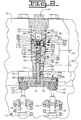
- a valve actuation system 10 for an internal combustion engine 12 is shown in Figs. 1-3.
- the engine 12 has a cylinder head 14 and one or more engine valve(s) 16 reciprocally disposed within the cylinder head 14.
- the engine valves 16 are only partially shown in Figs. 1-3 and may, for example, be a set of conventional exhaust or intake poppet valves.
- the valves 16 are each displaceable between a first closed position, shown partially in Fig. 2, and a second open position, shown partially in Fig. 3.
- the valves 16 are biased toward the first position by any suitable means, such as by helical compression springs 18.
- the internal combustion engine 12 could be a multi-stroke cycle or any suitable stroke cycle engine.
- the engine 12 will be further described as having only a single cylinder, however, it should be understood that the valve actuation system would function as intended in a multiple cylinder engine.
- the actuator head 20 has a axially extending bore 22 therethrough of varying diameters. Additionally, the actuator head 20 has a rail passage 24 therein selectively communicating between a low pressure fluid source 26 and a high pressure fluid source 28, as shown more clearly in Fig. 1.
- the fluid pressure of the fluid from the high pressure fluid source 28 is preferably greater than 1.1 x 10 6 kg/m 2 (1500 psi), and more preferably greater than 2.1 x 10 6 kg/m 2 (3000 psi).
- the fluid pressure of the fluid from the low pressure fluid source is preferably less than 2.8 x 10 5 kg/m 2 (400 psi), and more preferably, less than 1.4 x 10 5 kg/m 2 (200 psi).
- a cylindrical body 30 is sealingly fitted within the bore 22 by a plurality of o-rings 32 and has an axially extending bore 36. However, any suitable connection or sealing means may be used to fit the body 30 within the bore 22.
- a bridge 46 of any suitable type is disposed within a groove 48 in the actuator head 20 and is adjacent the body 30. The bridge 46 has a bore 50 with a predetermined length which is coaxially aligned with the bore 36 in the body 30.
- a plunger 54 with a plunger surface 58 is securely fitted within the bore 50 of the bridge 46 at an end 60 with a portion of the plunger 54 slidably disposed within the bore 36 of the body 30 at an opposite end 62.
- the opposite end 62 of the plunger 54 has a frusto-conical shape 64 which diverges from plunger surface 58 at a predetermined angle which can be seen in more detail in Fig. 4.
- the plunger 54 may be integrally formed with or separately connected to the bridge 46, such as by press fitting.
- the plunger 54 is operatively associated with the valves 16 and is movable between a first position and a second position. The movement of the plunger 54 toward the second position moves the valves 16 to their open position.
- the plunger 54 is biased to the first position by the helical springs 18. It should be understood that the plunger 54 may be used to directly actuate the engine valves 16 without the use of a bridge 46. In this manner, the plunger 54 would be integrally formed with or separately positioned adjacent the engine valves 16.
- a means 68 for communicating low pressure fluid into the bridge 46 is provided in close proximity to end 60.
- the communicating means 68 includes a pair of orifices 69 disposed within the bridge 46 and a pair of connecting passages 70 extending through the orifices 69 and the bridge 46 and into the plunger 54.
- a longitudinal bore 74 extends a predetermined distance into the plunger 54 and is in fluid communication with the connecting passages 70 within the bridge 46.
- An orificed passage 80 extends outwardly from the longitudinal bore 74.
- a cross bore 84 extends through the body 30 at a lower end 90 in close proximity to the end 60 of the plunger 54. The cross bore 84 is connected to a lower annular cavity 94 defined between the body 30 and the actuator head 20 for fluid communication therewith.
- the lower annular cavity 94 is in communication with the low pressure fluid source 26 through a passage 96 connected to the rail 24 in the actuator head 20.
- the cross bore 84 has a predetermined position relative to the orificed passage 80.
- a pair of hydraulic lash adjustors 100,102 are secured within a pair of large bores 106,107, respectively, in the bridge 46 by any suitable means, such as a pair of retaining rings 108,110.
- the lash adjustors 100,102 are in fluid communication with the orifices 69 and the connecting passages 70 and are adjacent the engine valves 16. However, it should be understood that the lash adjustors 100, 102 may or may not have the orifices 69 dependent upon the internal design used.
- a plug 120 is connected to the actuator head 20 and is sealingly fitted into the bore 50 at an upper end 124 of the body 30 in any suitable manner, such as by threading or press fitting.
- a plunger cavity 130 is formed within the bore 50 between the plug 120 and the plunger surface 58. It should be understood that although a plug 120 is shown fitted within the bore 50 to define the plunger cavity 130, the actuator head 20 may be sealingly fitted against the bore 22. Therefore, the plunger cavity 130 would be defined between the actuator head 20 and the plunger surface 58.
- a first means 140 for selectively communicating fluid from the high pressure fluid source into the plunger cavity 130 is provided for urging the plunger 54 toward the second position.
- the first communicating means 140 includes means 144 defining a primary flow path 148 between the high pressure fluid source and the plunger cavity 130 during initial movement toward the second position.
- the means 144 further defines a secondary flow path 152 between the high pressure fluid source and the plunger cavity 130 during terminal movement toward the second position.
- a control valve preferably a spool valve 156, communicates fluid through the high pressure rail passage 24 and into the primary and secondary flow path 148,152.
- the spool valve 156 is biased to a first position by a pair of helical compression springs (not shown) and moved against the force of the springs (not shown) to a second position by an actuator 158.
- the actuator 158 may be of any suitable type, however, in this embodiment the actuator 158 is a piezoelectric motor.
- the piezoelectric motor 158 is driven by a control unit 159 which has a conventional on/off voltage pattern.
- the primary flow path 148 of the first communication means includes an annular chamber 160 defined between the body 30 and the actuator head 20.
- a main port 164 is defined within the body 30 in fluid communication with the annular chamber 160 and has a predetermined diameter.
- An annular cavity 168 is defined between the plunger 54 and the body 30 and has a predetermined length and a predetermined position relative to the main port 164.
- the annular cavity 168 is in fluid communication with the main port 164 during a portion of the plunger 54 movement between the first and second positions.
- a passageway 170 is disposed within the plunger 54 and partially transverses the annular cavity 168 for fluid communication therewith.
- a first check valve 174 is seated within a bore 176 in the plunger 54 and has an orifice 178 therein in fluid communication with the passageway 170.
- the first check valve 174 has an open position and a closed position and the orifice 178 has a predetermined diameter.
- a stop 180 is seated within another bore 182 in the plunger 54 and is disposed a predetermined distance from the first check valve 174.
- the stop 180 has an axially extending bore 184 for fluidly communicating the orifice 178 with the plunger cavity 130 and a relieved outside diameter.
- a return spring 183 is disposed within the first check valve 174 between the valve 174 and the stop 180.
- the secondary flow path 152 of the first communicating means 140 includes a restricted port 190 which has a diameter less than the diameter of the main port 164.
- the restricted port 190 fluidly connects the annular chamber 160 to the annular cavity 168 during a portion of the plunger 54 movement between the first and second positions.
- a second means 200 for selectively communicating fluid exhausted from the plunger cavity 130 to the low pressure fluid source 26 in response to the helical springs 18 is provided for urging the plunger 54 toward the first position.
- the second communicating means 200 includes means 204 defining a primary flow path 208 between the plunger cavity 130 and the low pressure fluid source 26 during initial movement from the second position toward the first position.
- the means 144 further defines a secondary flow path 210 between the plunger cavity 130 and the low pressure fluid source 26 during terminal movement from the second position toward the first position.
- the spool valve 156 selectively communicates fluid through the primary and secondary flow path 208,210 and into the low pressure rail.
- the primary flow path 208 of the second communicating means 200 includes a second check valve 214 seated within a bore 216 in the body 30 with a portion of the second check valve 214 extending into the annular chamber 160.
- the second check valve 214 has an open and a closed position.
- a small conical shaped return spring (not shown) is disposed within the second check valve 214.
- An outlet passage 218 is defined within the body 30 between the second check valve 214 and the plunger 54. The outlet passage 218 provides fluid communication between the plunger cavity 130 and the annular chamber 160 when the second check valve is in the open position during a portion of the plunger 54 movement between the second and the first position.
- the secondary flow path 210 of the second communicating means 200 includes the orifice 178 being fluidly connected to the low pressure source 26 during a portion of the plunger 54 movement between the second and first positions.
- a first hydraulic means 230 is provided for reducing the plunger 54 velocity as the valves 16 approach the open position.
- the first hydraulic means 230 includes restricting fluid communication to the annular cavity 168 from the high pressure fluid source 28 through the main port 164 during a portion of the plunger 54 movement between the first and second positions and blocking fluid communication to the annular cavity 168 from the high pressure fluid source 28 through the main port 164 during a separate portion of the plunger 54 movement between the first and second positions.
- a second hydraulic means 240 is provided for reducing the plunger 54 velocity as the valves 16 approach the closed position.
- the second hydraulic means 240 includes the frusto-conical shaped end 62 of the plunger 54 restricting fluid communication to the low pressure fluid source 26 from the plunger cavity 168 through the outlet passage 218 and blocking fluid communication to the low pressure fluid source 26 from the plunger cavity 168 through the outlet passage 218.
- the following sequence begins with the plunger 54 in the first position, and therefore, the valve in the closed (or seated) position.
- voltage from the control unit is sent to the piezoelectric motor 158 which, in turn, drives the spool valve 156 in a known manner from the first position P1 to the second position P2. Movement of the spool valve 156 from the first position P1 to the second position P2 closes off communication between the low pressure fluid source 26 and the plunger cavity 130 and opens communication between the high pressure fluid source 28 and the plunger cavity 130.
- high pressure fluid from the high pressure fluid source 28 is communicated to the plunger cavity 130 through the primary flow path 148.
- the high pressure fluid unseats the first check valve 174 allowing the majority of high pressure fluid to enter the plunger cavity 130 around the first check valve 174 through the relieved outside diameter of the stop 180 at a rapid rate.
- the plunger 54 moves rapidly downward opening the valves 16 against the force of the springs 18.
- the position of the annular cavity 168 in relation to the main port 164 is constantly changing.
- the downward motion of the annular cavity 168 allows fluid connection between the annular cavity 168 and the restricted port 190, thereby allowing high pressure fluid to enter the plunger cavity 130 through both the primary and secondary flow paths 148,152.
- the high pressure fluid within the plunger cavity 130 unseats the second check valve 214 since low pressure fluid is now within the annular chamber 160.
- the unseating of the second check valve 214 allows the majority of fluid within the plunger cavity 130 to rapidly return to the low pressure fluid source 26 through the primary flow path 208.
- a portion of the high pressure fluid within the plunger cavity 130 is returned to the low pressure fluid source 26 through the secondary flow path as the orifice 178 fluidly connects with the annular chamber 160 during the terminal plunger movement from the second position to the first position.
- the spool valve 156 when the spool valve 156 is in the P1 position and connected with the low pressure fluid source 26, fluid is communicated to the hydraulic adjustors 100,102 through the orifices 69.
- the orifices 69 communicate with the passages 70 to control the maximum pressure allowed for the lash adjustors 100,102.
- the plunger 54 when the spool valve moves into the P2 position, the plunger 54 is moved downwards and the orificed passage 80 moves past the cross bore 84 restricting and eventually blocking fluid communication form the low pressure fluid source 26 to the adjustors 100,102.
- Fig. 5 shows the optimized valve lift curve related to the design of the present invention.
- Point A is related to the initial control signal to the spool valve 156 moving the spool valve 156 from P1 to P2.
- Point B is relates to the first check valve 174 unseating and resulting in rapid valve 16 opening.
- Point C is related to the blocking of the main bore 164.
- Curve D is related to the limiting the fluid communication to the plunger cavity 130 through the restricted port 190.
- Point E is related to the blocking of the restricted port 190.
- Line F is related to the maximum valve lift.
- Point G is related to the terminal control signal to the spool valve 156 moving the spool valve 156 from P2 to P1.
- Point H is related to the rapid discharge through the second check valve 214.
- Curves I&J are related to the frusto-conical end 62 of the plunger 54 restricting fluid communication from the plunger cavity 130 through the outlet passage 218.
- Point K relates to the fine velocity control achieved through blocking the fluid communication from the plunger cavity 130 through the outlet passage 218 so that all fluid communication from the plunger cavity 130 to the low pressure fluid source 26 is through the orifice 178.
- the use of hydraulic means for reducing the plunger velocity during the opening and closing of the valve provides a simple method for controlling the valve lift and valve seating.
- the present invention does not rely on expensive or complicated electronic systems for controlling velocity and is therefore more dependable.
Landscapes
- Engineering & Computer Science (AREA)
- Mechanical Engineering (AREA)
- General Engineering & Computer Science (AREA)
- Valve Device For Special Equipments (AREA)
Description
However, most advanced electronic control systems are in varying stages of development and are, therefore, not feasible for internal combustion engines currently in production. Additionally, without proven results, the costs and complexity of the advanced electronic control systems may exceed the benefits of such a system.
Claims (17)
- A valve actuation system (10) adapted for use with an internal combustion engine (12) having a cylinder head (14) and a valve (16) disposed within the cylinder head (14), the valve (16) having an open and a closed position, comprising:an actuator head (20) with a bore (22) therein connected to the cylinder head (14);a cylindrical body (30) adapted for connection within the bore (22) in the actuator head (20), the body (30) having an axially extending bore (36) therethrough;a plunger (54) operatively associated with the valve (16) and having a plunger surface (58), the plunger (54) operatively associated with the cylinder head (14) to define a plunger cavity (130) and being slidably disposed partially within the bore (36) in the body (30) and being movable between a first position and a second position;a source of relatively high pressure fluid (28);a source of relatively low pressure fluid (26);means (18) for biasing the plunger (54) towards the first position;first means (140) for selectively communicating fluid from the high pressure source (28) into the plunger cavity (130) for urging the plunger (54) toward the second position so that the valve (16) is moved to the open position;second means (200) for selectively communicating fluid exhausted from the plunger cavity (130) to the low pressure source (26) in response to the biasing means (18) urging the plunger (54) toward the first position so that the valve (16) is moved to the closed position;and hydraulic means (230, 240) for reducing the plunger (54) velocity as the valve (16) approaches the open and closed positions; wherein the plunger cavity is a single cavity (130), and the hydraulic means (230, 240) reduces the plunger velocity by regulating the flow into and out of the single cavity (130); and wherein the first communication means (140) includes means (144) defining a primary flow path (148) between high pressure source (28) and the plunger cavity (130) during initial movement toward the second position; characterised in that the primary flow path (148) of the first communication means (140) includes a passageway (170) disposed within the plunger (54) and a first check valve (174) seated within a bore (176) in the plunger (54), the first check valve (174) comprising an orifice (178) in fluid connection with the passageway (170), the first check valve (174) having an open position permitting a substantially unrestricted flow path in one direction and a closed position permitting a substantially restricted flow path in an opposite direction.
- A valve actuation system according to claim 1, further comprising a secondary flow path (152) between the high pressure source (28) and the plunger cavity (130) during terminal movement toward second position.
- A valve actuation system according to claim 1 or claim 2, wherein the second communication means (200) includes means (204) defining a primary flow path (208) between the plunger cavity (130) and the low pressure source (26) during initial movement from the second position toward the first position and a secondary flow path (210) between the plunger cavity (130) and the low pressure source (26) during terminal movement from the second position toward the first position.
- A valve actuation system (10) according to any one of the preceding claims, wherein the primary flow path (148) of the first communication means (140) includes an annular chamber (160) defined between the actuator head (20) and the body (30) and a main port (164) having a predetermined diameter defined within the body (30) in fluid connection with the annular chamber(160).
- A valve actuation system (10) according to claim 4, wherein the primary flow path (148) of the first communication means (140) includes an annular cavity (168) having a predetermined length and a predetermined position in relation to the main port (164), the annular cavity (168) being defined between the plunger (54) and the body (30) in fluid connection with the main port (164) during a portion of the plunger (54) movement between the first and second positions.
- A valve actuation system (10) according to claim 5, wherein the passageway (170) partially traverses the annular cavity (168) for fluid connection therewith.
- A valve actuation system (10) according to any one of the preceding claims, wherein the primary flow path (148) of the first communication means (140) includes a stop (18) disposed a predetermined distance from the first check valve (174), the stop (180) having an axially extending bore (184) for fluidly connecting the orifice (178) in the first check valve (174) with the plunger cavity (130).
- A valve actuation system (10) according to claim 6 or claim 7, wherein the orifice (178) in the first check valve (174) has a predetermined diameter.
- A valve actuation system (10) according to claim 4 when dependent on claim 2, wherein the secondary flow path (152) of the first communication means (140) includes a restricted port (190) having a diameter less than the diameter of the main port (164), the restricted port (190) fluidly connects the annular chamber (160) to the annular cavity (168) during a portion of the plunger (54) movement between the first and second positions.
- A valve actuation system (10) according to claim 4 when dependant on claim 3, wherein the primary flow path (208) of the second communicating means (200) includes a second check valve (214) disposed within the body (30) and seated within a portion of the annular chamber (160) and an outlet passage (218) disposed between the plunger cavity (130) and the annular chamber (160) via the second check valve (214) for fluid communication therebetween during a portion of the plunger (54) movement between the second and first positions.
- A valve actuation system (10) according to claim 3, wherein the secondary flow path (210) of the second communication means (200) includes the orifice (178) within the first check valve (174) fluidly connected to the low pressure source (26) during a portion of the plunger (54) movement between the second and first positions.
- A valve actuation system (10) according to claim 5, wherein the hydraulic means (230,240) for reducing the plunger (54) velocity as the valve (16) approaches the open position includes restricting fluid communication to the annular cavity (168) from the high pressure source (28) through the main port (164).
- A valve actuation system (10) according to claim 5 and claim 9, wherein the hydraulic means (230,240) for reducing the plunger (54) velocity as the valve (16) approaches the open position includes blocking fluid communication to the annular cavity (168) from the annular chamber (160) through the main port (164).
- A valve actuation system (10) of claim 13, wherein the valve (16) reaches the maximum open position when fluid communication is blocked to the annular cavity (168) from the annular chamber (160) through the restricted port (190).
- A valve actuation system (10) according to claim 10, wherein the hydraulic means (230,240) for reducing the plunger (54) velocity as the valve (16) approaches the closed position includes the plunger (54) having a frusto-conical end (64) for restricting the fluid communication to the low pressure source (26) from the plunger cavity (130) through the outlet passage (218).
- A valve actuation system (10) according to claim 10, wherein the hydraulic means (230,240) for reducing the plunger (54) velocity as the valve (16) approaches the closed position includes blocking the fluid communication to the low pressure source (26) from the plunger cavity (130) through the outlet passage (218).
- An internal combustion engine (12) having a cylinder head (14) and a valve actuation system (10) according to any one of the preceding claims disposed within the cylinder head (14).
Applications Claiming Priority (3)
| Application Number | Priority Date | Filing Date | Title |
|---|---|---|---|
| US08/286,068 US5531192A (en) | 1994-08-04 | 1994-08-04 | Hydraulically actuated valve system |
| US286068 | 1994-08-04 | ||
| PCT/US1995/008573 WO1996004469A1 (en) | 1994-08-04 | 1995-07-10 | Hydraulically actuated valve system |
Publications (2)
| Publication Number | Publication Date |
|---|---|
| EP0722536A1 EP0722536A1 (en) | 1996-07-24 |
| EP0722536B1 true EP0722536B1 (en) | 1998-11-25 |
Family
ID=23096930
Family Applications (1)
| Application Number | Title | Priority Date | Filing Date |
|---|---|---|---|
| EP95925573A Expired - Lifetime EP0722536B1 (en) | 1994-08-04 | 1995-07-10 | Hydraulically actuated valve system |
Country Status (5)
| Country | Link |
|---|---|
| US (1) | US5531192A (en) |
| EP (1) | EP0722536B1 (en) |
| JP (1) | JP3811501B2 (en) |
| DE (1) | DE69506219T2 (en) |
| WO (1) | WO1996004469A1 (en) |
Families Citing this family (36)
| Publication number | Priority date | Publication date | Assignee | Title |
|---|---|---|---|---|
| US5647318A (en) | 1994-07-29 | 1997-07-15 | Caterpillar Inc. | Engine compression braking apparatus and method |
| DE19501495C1 (en) * | 1995-01-19 | 1995-11-23 | Daimler Benz Ag | Hydraulic valve control device for I.C. engine |
| US5709178A (en) * | 1996-04-22 | 1998-01-20 | Caterpillar Inc. | Electronically controlled outwardly opening valve system for an engine |
| US5829396A (en) * | 1996-07-16 | 1998-11-03 | Sturman Industries | Hydraulically controlled intake/exhaust valve |
| US5724939A (en) * | 1996-09-05 | 1998-03-10 | Caterpillar Inc. | Exhaust pulse boosted engine compression braking method |
| DE29704758U1 (en) * | 1997-03-15 | 1997-05-07 | FEV Motorentechnik GmbH & Co. KG, 52078 Aachen | Hydraulic switching unit |
| BR9815101A (en) * | 1997-11-21 | 2001-04-03 | Diesel Engine Retarders Inc | Valve actuation system for actuating engine valves in an internal combustion engine |
| IT1302071B1 (en) * | 1998-02-26 | 2000-07-20 | Fiat Ricerche | INTERNAL COMBUSTION ENGINE WITH VARIABLE OPERATION VALVES. |
| US5937807A (en) * | 1998-03-30 | 1999-08-17 | Cummins Engine Company, Inc. | Early exhaust valve opening control system and method |
| US6273057B1 (en) | 1998-08-19 | 2001-08-14 | Diesel Engine Retarders, Inc. | Hydraulically-actuated fail-safe stroke-limiting piston |
| US6786186B2 (en) * | 1998-09-09 | 2004-09-07 | International Engine Intellectual Property Company, Llc | Unit trigger actuator |
| US6135073A (en) * | 1999-04-23 | 2000-10-24 | Caterpillar Inc. | Hydraulic check valve recuperation |
| IT1307361B1 (en) * | 1999-10-06 | 2001-11-06 | Fiat Ricerche | IMPROVEMENTS TO INTERNAL COMBUSTION ENGINES WITH VARIABLE ADJUSTMENT VALVES. |
| US6349686B1 (en) | 2000-08-31 | 2002-02-26 | Caterpillar Inc. | Hydraulically-driven valve and hydraulic system using same |
| US6739293B2 (en) * | 2000-12-04 | 2004-05-25 | Sturman Industries, Inc. | Hydraulic valve actuation systems and methods |
| US6474620B2 (en) * | 2000-12-20 | 2002-11-05 | Caterpillar Inc | Method of controlling hydraulically actuated valves and engine using same |
| DE10147305A1 (en) * | 2001-09-26 | 2003-04-17 | Bosch Gmbh Robert | Internal combustion engine |
| US6578536B1 (en) | 2001-12-18 | 2003-06-17 | Visteon Global Technologies, Inc. | Actuator assembly for electrohydraulic operation of cylinder valves |
| US7004122B2 (en) * | 2002-05-14 | 2006-02-28 | Caterpillar Inc | Engine valve actuation system |
| US7069887B2 (en) * | 2002-05-14 | 2006-07-04 | Caterpillar Inc. | Engine valve actuation system |
| US20030213444A1 (en) * | 2002-05-14 | 2003-11-20 | Cornell Sean O. | Engine valve actuation system |
| DE10226254A1 (en) * | 2002-06-13 | 2003-12-24 | Bosch Gmbh Robert | Hydraulically controlled actuator for actuating an exhaust gas exchange valve of an internal combustion engine |
| US20040003786A1 (en) * | 2002-06-18 | 2004-01-08 | Gatecliff George W. | Piezoelectric valve actuation |
| AU2003261152A1 (en) * | 2002-07-11 | 2004-02-02 | Sturman Industries, Inc. | Hydraulic valve actuation methods and apparatus |
| ITBO20030390A1 (en) * | 2003-06-23 | 2004-12-24 | Magneti Marelli Powertrain Spa | METHOD AND VALVE SPEED CONTROL DEVICE |
| US7318398B2 (en) * | 2003-08-15 | 2008-01-15 | Caterpillar Inc. | Engine valve actuation system |
| US6988471B2 (en) * | 2003-12-23 | 2006-01-24 | Caterpillar Inc | Engine valve actuation system |
| WO2005089274A2 (en) * | 2004-03-15 | 2005-09-29 | Jacobs Vehicle Systems, Inc. | Valve bridge with integrated lost motion system |
| US7204212B2 (en) * | 2005-01-12 | 2007-04-17 | Temic Automotive Of North America, Inc. | Camless engine hydraulic valve actuated system |
| US7347172B2 (en) * | 2005-05-10 | 2008-03-25 | International Engine Intellectual Property Company, Llc | Hydraulic valve actuation system with valve lash adjustment |
| JP5094732B2 (en) * | 2005-12-28 | 2012-12-12 | ジェイコブス ビークル システムズ、インコーポレイテッド | Partial cycle bleeder type braking method and system |
| JP4929761B2 (en) * | 2006-03-02 | 2012-05-09 | リコープリンティングシステムズ株式会社 | Optical scanning device and image forming apparatus using the same |
| US7460936B2 (en) * | 2006-05-12 | 2008-12-02 | Delphi Technologies, Inc. | System and method for controlling vehicle hydraulic system |
| GB2478285A (en) * | 2010-03-01 | 2011-09-07 | Mechadyne Plc | Valve mechanism for an internal combustion engine |
| EP2981687B1 (en) * | 2013-03-31 | 2019-10-23 | Jacobs Vehicle Systems, Inc. | Controlling motion of a moveable part |
| US10113453B2 (en) * | 2015-04-24 | 2018-10-30 | Randy Wayne McReynolds | Multi-fuel compression ignition engine |
Family Cites Families (7)
| Publication number | Priority date | Publication date | Assignee | Title |
|---|---|---|---|---|
| CH243908A (en) * | 1944-11-27 | 1946-08-15 | Schweizerische Lokomotiv | Fluid brake with check valve on the passive piston of hydraulically controlled valves of internal combustion engines. |
| DE3836725C1 (en) * | 1988-10-28 | 1989-12-21 | Daimler-Benz Aktiengesellschaft, 7000 Stuttgart, De | |
| JP2664986B2 (en) * | 1989-04-03 | 1997-10-22 | 三菱重工業株式会社 | Valve train for internal combustion engine |
| US5275136A (en) * | 1991-06-24 | 1994-01-04 | Ford Motor Company | Variable engine valve control system with hydraulic damper |
| US5255641A (en) * | 1991-06-24 | 1993-10-26 | Ford Motor Company | Variable engine valve control system |
| DE59201193D1 (en) * | 1991-10-23 | 1995-02-23 | New Sulzer Diesel Ag | Device for hydraulically actuating an exhaust valve of a reciprocating piston internal combustion engine. |
| JP3410125B2 (en) * | 1992-10-19 | 2003-05-26 | 同和鉱業株式会社 | Manufacturing method of high strength copper base alloy |
-
1994
- 1994-08-04 US US08/286,068 patent/US5531192A/en not_active Expired - Lifetime
-
1995
- 1995-07-10 EP EP95925573A patent/EP0722536B1/en not_active Expired - Lifetime
- 1995-07-10 JP JP50650396A patent/JP3811501B2/en not_active Expired - Fee Related
- 1995-07-10 DE DE69506219T patent/DE69506219T2/en not_active Expired - Fee Related
- 1995-07-10 WO PCT/US1995/008573 patent/WO1996004469A1/en active IP Right Grant
Also Published As
| Publication number | Publication date |
|---|---|
| DE69506219D1 (en) | 1999-01-07 |
| JP3811501B2 (en) | 2006-08-23 |
| WO1996004469A1 (en) | 1996-02-15 |
| JPH09504074A (en) | 1997-04-22 |
| EP0722536A1 (en) | 1996-07-24 |
| DE69506219T2 (en) | 1999-06-24 |
| US5531192A (en) | 1996-07-02 |
Similar Documents
| Publication | Publication Date | Title |
|---|---|---|
| EP0722536B1 (en) | Hydraulically actuated valve system | |
| EP0828061B1 (en) | Exhaust pulse boosted engine compression braking method | |
| US5373817A (en) | Valve deactivation and adjustment system for electrohydraulic camless valvetrain | |
| US6067955A (en) | Fuel injection device for internal combustion engines | |
| EP0317372B1 (en) | Apparatus for controlling valve operation in an internal combustion engine | |
| US6199533B1 (en) | Pilot valve controlled three-way fuel injection control valve assembly | |
| EP1429035B1 (en) | Switchable fluid control valve system | |
| US7387095B2 (en) | Hydraulic valve actuation systems and methods to provide variable lift for one or more engine air valves | |
| US6584885B2 (en) | Variable lift actuator | |
| US6135073A (en) | Hydraulic check valve recuperation | |
| EP1403473B1 (en) | Hydraulic valve actuation system | |
| US7665431B2 (en) | Drive piston assembly for a valve actuator assembly | |
| EP1464794B1 (en) | Engine valve aktuator assembly with dual hydraulic feedback | |
| US7228826B2 (en) | Internal combustion engine valve seating velocity control | |
| US5485813A (en) | Lost motion actuator with damping transition | |
| EP1549832B1 (en) | An arrangement of an internal combustion engine poppet valve and an actuator therefor | |
| JPH01262308A (en) | Engine valve actuating system | |
| US20040050350A1 (en) | Hydraulic actuator for a gas exchange valve | |
| US6857618B2 (en) | Device for controlling a gas exchange valve | |
| US6688289B2 (en) | Fuel injection system for internal combustion engines | |
| US20030213444A1 (en) | Engine valve actuation system | |
| US20040050354A1 (en) | Valve mechanism comprising a variable cross-section of a valve opening | |
| KR20040030072A (en) | Device for controlling gas exchange valves | |
| US20040025820A1 (en) | Valve mechanism with a variable valve opening cross-section | |
| JP2005507045A (en) | Device for controlling gas exchange valve |
Legal Events
| Date | Code | Title | Description |
|---|---|---|---|
| PUAI | Public reference made under article 153(3) epc to a published international application that has entered the european phase |
Free format text: ORIGINAL CODE: 0009012 |
|
| 17P | Request for examination filed |
Effective date: 19960419 |
|
| AK | Designated contracting states |
Kind code of ref document: A1 Designated state(s): DE FR GB |
|
| 17Q | First examination report despatched |
Effective date: 19961001 |
|
| GRAG | Despatch of communication of intention to grant |
Free format text: ORIGINAL CODE: EPIDOS AGRA |
|
| GRAG | Despatch of communication of intention to grant |
Free format text: ORIGINAL CODE: EPIDOS AGRA |
|
| GRAH | Despatch of communication of intention to grant a patent |
Free format text: ORIGINAL CODE: EPIDOS IGRA |
|
| GRAH | Despatch of communication of intention to grant a patent |
Free format text: ORIGINAL CODE: EPIDOS IGRA |
|
| GRAA | (expected) grant |
Free format text: ORIGINAL CODE: 0009210 |
|
| AK | Designated contracting states |
Kind code of ref document: B1 Designated state(s): DE FR GB |
|
| REF | Corresponds to: |
Ref document number: 69506219 Country of ref document: DE Date of ref document: 19990107 |
|
| ET | Fr: translation filed | ||
| PLBE | No opposition filed within time limit |
Free format text: ORIGINAL CODE: 0009261 |
|
| STAA | Information on the status of an ep patent application or granted ep patent |
Free format text: STATUS: NO OPPOSITION FILED WITHIN TIME LIMIT |
|
| 26N | No opposition filed | ||
| PGFP | Annual fee paid to national office [announced via postgrant information from national office to epo] |
Ref country code: FR Payment date: 20010720 Year of fee payment: 7 |
|
| REG | Reference to a national code |
Ref country code: GB Ref legal event code: IF02 |
|
| PG25 | Lapsed in a contracting state [announced via postgrant information from national office to epo] |
Ref country code: FR Free format text: LAPSE BECAUSE OF NON-PAYMENT OF DUE FEES Effective date: 20030331 |
|
| REG | Reference to a national code |
Ref country code: FR Ref legal event code: ST |
|
| PGFP | Annual fee paid to national office [announced via postgrant information from national office to epo] |
Ref country code: DE Payment date: 20070731 Year of fee payment: 13 |
|
| PGFP | Annual fee paid to national office [announced via postgrant information from national office to epo] |
Ref country code: GB Payment date: 20070618 Year of fee payment: 13 |
|
| GBPC | Gb: european patent ceased through non-payment of renewal fee |
Effective date: 20080710 |
|
| PG25 | Lapsed in a contracting state [announced via postgrant information from national office to epo] |
Ref country code: DE Free format text: LAPSE BECAUSE OF NON-PAYMENT OF DUE FEES Effective date: 20090203 |
|
| PG25 | Lapsed in a contracting state [announced via postgrant information from national office to epo] |
Ref country code: GB Free format text: LAPSE BECAUSE OF NON-PAYMENT OF DUE FEES Effective date: 20080710 |