EP1394306A2 - Reed for weaving - Google Patents
Reed for weaving Download PDFInfo
- Publication number
- EP1394306A2 EP1394306A2 EP03015497A EP03015497A EP1394306A2 EP 1394306 A2 EP1394306 A2 EP 1394306A2 EP 03015497 A EP03015497 A EP 03015497A EP 03015497 A EP03015497 A EP 03015497A EP 1394306 A2 EP1394306 A2 EP 1394306A2
- Authority
- EP
- European Patent Office
- Prior art keywords
- reed
- dents
- hollow portions
- weft
- reed dents
- Prior art date
- Legal status (The legal status is an assumption and is not a legal conclusion. Google has not performed a legal analysis and makes no representation as to the accuracy of the status listed.)
- Granted
Links
Images


Classifications
-
- D—TEXTILES; PAPER
- D03—WEAVING
- D03D—WOVEN FABRICS; METHODS OF WEAVING; LOOMS
- D03D49/00—Details or constructional features not specially adapted for looms of a particular type
- D03D49/60—Construction or operation of slay
- D03D49/62—Reeds mounted on slay
-
- D—TEXTILES; PAPER
- D03—WEAVING
- D03D—WOVEN FABRICS; METHODS OF WEAVING; LOOMS
- D03D47/00—Looms in which bulk supply of weft does not pass through shed, e.g. shuttleless looms, gripper shuttle looms, dummy shuttle looms
- D03D47/27—Drive or guide mechanisms for weft inserting
- D03D47/277—Guide mechanisms
- D03D47/278—Guide mechanisms for pneumatic looms
Definitions
- This invention relates to a reed for weaving such as a divided reed or a single reed used for a loom.
- a loom produces a cloth, repeating such steps as: dividing a plurality of warps into a plurality of groups of the warps; forming a warp shedding by vertically moving in every group those warp groups with a shedding device; making the weft run into the shedding; and thereafter, beating the weft with a reed for weaving including a plurality of reed dents.
- Each reed dent has a projected portion in a front edge section located at one side. In the projected portion, a hollow portion is formed, and a rear edge section located at the other side is made flat.
- the reed is formed by combining the plurality of the reed dents with the hollow portions communicated with each other so as to form guide groove for the weft.
- the guide grooves in both prior techniques have a so-called tapered shape such that the depth of the hollow portions of the reed dents located at the weft insert side are larger than that of the hollow portions of the other reed dents, and the nearer the central side in the insert direction they are located, the smaller (shallower) the depth becomes so as to become approximate to the depth of the hollow portions of the other reed dents.
- the other reed dents is meant, more specifically, the remaining reed dents between which the warps are to be passed.
- the shape of the rear edge section of each reed dent located at the weft insert side is made substantially flat just like the shape of the rear edge section of another reed dent; therefore, if the depth of the hollow portion is enlarged so as to enlarge the tapered shape of the guide groove, the distance between the hollow portion and the rear edge section is remarkably shortened, thereby lowering the strength of the reed dent itself.
- An object of the present invention is to provide a guide groove to facilitate weft insertion without lowering the strength of the reed dent.
- the reed according to the present invention has a plurality of reed dents each of which includes a front edge section and a rear edge section, and the reed dents each of which has a hollow portion for guiding the weft in the front edge section are arranged such that the hollow portions are communicated with each other so as to form a guide groove.
- the depth of the hollow portions of the reed dents located at least at one end portion in the weft insert direction are larger than that of the hollow portions of the other reed dents, and the nearer the central side in the weft insert direction, the smaller the depth of the hollow portions of the reed dents are made so as to become approximate to the depth of the hollow portions of the other reed dents, and areas including positions corresponding to the hollow portions in the rear edge sections of the reed dents the one end portion are projected backward.
- the above-mentioned reed is assembled into the loom, making larger the depth of the hollow portions of the reed dents at the weft insert side.
- the area including the portion corresponding to the hollow portion in the rear edge section of each reed dent located at the weft insert side is projected backward, the strength of the reed dents is not lowered even if the depth of the hollow portions of the reed dents is enlarged and the facility and smoothness in the weft insertion are raised.
- the reed according to the present invention may be applied to a so-called single reed whose plurality of reed dents are assembled into common upper and lower caps (fixing members), or may be applied to a so-called divided reed whose plurality of reed dents are assembled into upper and lower caps.
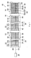
- the reed 10 for weaving has a divided reed 12 of the first width, a divided reed 14 of the second width and a divided reed 16 of the third width (the last width) arranged in series at intervals in the weft insert direction (rightward and leftward direction).
- the weft 18 is jetted from a weft insert nozzle 20 together with the compressed air and inserted into a warp shedding.
- Each of the divided reeds 12, 14, 16 has a plurality of reed dents (i.e. reed blade) 22 arranged in parallel to each other at intervals in the weft insert direction, and forms a guide groove 26 for the weft 18 by the hollow portion 24 formed in the reed dents 22.
- Each hollow portion 24 has a one-side open rectangular shape with the corners rounded by the upper and lower faces 24a, 24a and the depth bottom portion (depth bottom face) 24b.
- each reed dent 22 is shaped like a band elongated in the vertical direction and having a substantially constant thickness with both front end portions rounded.
- Each reed dent 22 has a front edge section 30 which is to be a cloth fell side, and a rear edge section which is to be a non-cloth fell side, as explained later.
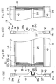
- Each of the divided reeds 12, 14, 16 is formed, like the reed 28 for weaving shown in Figs. 3 and 4, by a plurality of reed dents 22, upper and lower caps (attaching members) 34, 36, and right and left side caps (connecting members) 38, 40.
- Each guide groove 26 is formed by making the hollow portion 24 in each reed dent 22 communicated with each of the divided reeds 12, 14, 16.
- the upper and lower parts of the reed dents 22 are inserted into a groove 34a of the upper cap 34 and a groove 36a of the lower cap 36, respectively, having a one-side open rectangular sectional shape, such that the reed dents 22 are juxtaposed in the weft insert direction and that their thickness direction is made to be the weft insert direction and so that the hollow portions of every divided reed can be aligned to form a guide groove 26.
- a space between adjacent reed dents 22 is made to be a space 44 for passing the warp by a pair of spacers 42 disposed at an interval in the vertical direction (See Fig. 4).
- the spacer 42 is a compressive or tensile type coil spring, and each ring-shaped part of the coil spring 42 is located between the adjacent reed dents 22 to maintain the space.
- the reed 28 for weaving can be assembled, with a plurality of reed dents 22 arranged as mentioned above, by inserting side caps 38 and 40 acting as master blades into the weft insert side and the non-insert side and attaching the side caps 38 and 40 respectively to the upper and lower caps 34 and 36 with rivets, stopping screws, or the like.
- Each of the side caps 38, 40 is formed in a one-side open rectangular shape with both end portions of a band-like plate slightly thicker than the reed dent 22 bent in the thickness direction, and attached to the upper and lower caps 34, 36 so as not to block the hollow portion 24 of the reed dent 22 positioned at the end portion.
- the side caps 38 and 40 can have substantially the same vertical dimension as the dimension from the rear edge section 32 to the hollow portion 24 of the reed dent 22 at the weft insert side end and the non-insert side end.
- the divided reeds 12, 14, 16 using the reed 28 for weaving assembled as mentioned above are incorporated in series into a reed sleigh (not shown) attached to an arm (not shown) in the lower cap 36 such that the guide grooves 26 are located in the area where there is the warp and are communicated with each other and so as to oppose the cloth fell of the cloth.
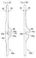
- each reed dent 22 has a projected portion 46 near the center of the front edge section 30 which is the cloth fell side of the cloth, and has the hollow portion 24 in the projected portion 46.
- the position of the depth bottom part 24b of the hollow portion 24 of the reed dent 22a located at the weft insert side end portion is a position toward the side of the rear edge section 32 from the extended line of the front edge section 30 in the forward and backward direction. Therefore, the depth of the hollow portion of each reed dent 22a can be enlarged.
- the central area in the vertical direction including the portion corresponding to the hollow portion 24 is projected as a projected area 48, which is more outward than both end portions of the rear edge section 32 of the reed dent to be inserted into the upper and lower caps 34, 36 in the forward and backward direction.
- the range of the projected area 48 of the reed dent 22a is substantially the same as the range of the projected portion 46.
- the shape of the projected area 48 is substantially trapezoidal in this figure but is not limited to it. It suffices for the projected area 48 to have a range and a shape by which the strength of the reed dent 22a can be maintained.
- the projected area 48 may be shaped like a circular arc so that the vertical dimension from the rear edge section of the projected area 48 to the depth bottom part 24b may be constant.
- each of the other reed dents 22b is, as shown in Fig. 2(B), substantially in the same position as the extended line of the front edge section 30 in the forward and backward direction.
- the other rear edge section 32 of each of the other reed dents 22b is linear (i.e., flat) over the entire length in the vertical direction of the reed dent 22b.
- the depths of the hollow portions 24 of the other reed dents 22b are the same. However, the vertical dimension from the depth bottom part 24b to the rear edge section 32 of each reed dent 22b is made substantially the same as the vertical dimension of the lower end portion area of the reed dent 22b. It is intended thereby to keep the mechanical strength uniform in the entire reed dent 22b and to lighten each divided reed.
- the depths of the hollow portions 24 of the reed dents 22a located at the end portion on the weft insert side are made larger than the depths of the hollow portions 24 of the other reed dents 22b shown in Fig. 2(B), and the nearer the central side in the weft insert direction, the smaller the depths the hollow portions 24 of the reed dents 22a are made so as to become approximate to the depths of the hollow portions 24 of the other reed dents 22b. Therefore, the depth of the guide groove 26 of each divided reed is gradually shallowed from the weft insert side toward the non-insert side and is made constant from halfway in the weft insert direction.
- the projected areas 48 are provided at the rear edge sections 32, so that the vertical dimension from the rear edge section of the projected area 48 to the depth bottom part 24b of the hollow portion 24 can be made substantially the same as the dimension between the upper and lower end areas of the reed dent 22a, or the dimension from the depth bottom part 24b to the rear edge section 32 of the reed dent 22b. Therefore, also in the reed dent 22a, the mechanical strength around the hollow portion 24 does not become lower than the strength of the other portion.
- the vertical dimensions of the hollow portions 24 of the reed dents 22a located at the weft insert side be gradually made narrower toward the central side in the weft insert direction, and that the vertical dimension of the hollow portion 24 of the reed dent 22a nearest to the other reed dent 22b be made larger than the vertical dimension of the hollow portion 24 of the other reed dent 22b so as to become the most approximate to the vertical dimension of the hollow portion 24 of the other reed dent 22b.
- the vertical dimension of the guide groove 26 of each divided reed is gradually narrowed from the weft insert side toward the non-insert side and made constant from halfway in the weft insert direction.
- the guide groove 26 may be tapered not only in the depth direction but also in the cross direction.
- every reed dent 22a may have the projected area 48 of a size different from others.
- the sizes of the projected areas 48 may be gradually made smaller toward the non-insert side.
- the projected area 48 projecting backward in the central area of the rear edge section 32 of the reed dent 22a the depth of the hollow portion 24 of the reed dent 22a can be enlarged, while if such a projected area is not formed in the other reed dent 22b, the strength of the reed dent 22a is not lowered, so that, though the entire divided reed is light, the mechanical strength thereof is not lowered.
- the dimension in the forward and backward direction of the reed dent 22b becomes small, so that the divided reed becomes light as a whole, and the inertial force of the divided reed accompanying the beating motion becomes small.
- the beating time can be shortened and the loom can be operated at a high speed.
- All of the divided reeds 12, 14, 16 can have the shape as mentioned above, but they may have other shapes, for example, the shape shown in Fig. 5.
- the divided reed 16 in the last width (the non-insert side) preferably has the shape shown in Fig.5.
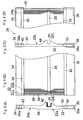
- the reed 50 for weaving is formed to be the same as the reed 28 for weaving as shown in Figs. 3 and 4, except that it has two spacers 42 at the upper side and that the side master blade 52 located at the end portion on the weft non-insert side is formed with a band-like plate member having substantially the same thickness as the vertical dimension from the rear edge section 32 to the depth bottom portion 24b of the hollow portion 24 of the reed dent 22b.
- the reed 50 for weaving shown in Fig.5 can be used like the reed 28 for weaving shown in Figs. 3 and 4, thereby bringing about substantially the same action and effect as when the reeds 28 for weaving as shown in Figs. 3 and 4 are used.
- Fig. 6 shows, in contrast to the embodiment in Fig. 3, the reed in which the vertical dimension of the hollow portions of the reed dents located at the end portion on the non-insert side is made smaller toward the non-insert side. If this reed 28 for weaving is used, the facility and smoothness in weft insertion of the reed dents at the non-insert side are improved.
- the structures of the reeds 28 for weaving shown in Figs. 3, 4 and 6 and that of the reed 50 for weaving shown in Fig. 5 can be applied to a single reed formed integrally with a plurality of reed dents arranged at intervals in the weft insert direction.
- the hollow portions 24 of the reed dents 22a located at the weft insert side are formed like the reed dent 22a in the above embodiment.
- the guide grooves 26 of all the divided reeds may be tapered.
- the reed used for the loom to insert the weft from the right side is formed such that the hollow portions 24 of the reed dents located at the right end portion are shaped like the foregoing reed dents 22a.
- the reed to be used for the loom which inserts the weft from both right and left sides are formed such that the hollow portions 24 of the reed dents located at each of the right and left end portions have such a shape as the foregoing reed dents 22a.
- a plurality of reed dents located at least at one end portion in the rightward and leftward direction have the hollow portions 24 like the forgoing reed dent 22a.
- the present invention is not limited to the above embodiments but can be variously modified without departing from its purport.
Landscapes
- Engineering & Computer Science (AREA)
- Textile Engineering (AREA)
- Looms (AREA)
Abstract
Description
Claims (5)
- A reed for weaving, wherein a plurality of reed dents (22), each including a front edge section (30) and a rear edge section (32), the reed dents (22) having hollow portions (24) for guiding the weft, are arranged such that said hollow portions (24) are communicated with each other so as to form guide grooves (26) for the weft (18),
wherein the depths of said hollow portions (24) of the reed dents (22) located at least at one end portion in the weft insert direction are made larger than the depths of the hollow portions (24) of other reed dents (22) and, the nearer the central side in the weft insert direction the reed dents (22) are located, the smaller the depths of the hollow portions (24) are made so as to become approximate to the depths of said hollow portions (24) of said other reed dents (22), and
wherein, in said reed dents (22) at the one end portion, areas including portions corresponding to said hollow portions (24) in said rear edge sections (32) are projected backward. - A reed described in claim 1, wherein the vertical dimension between the upper and lower parts of the hollow portions (24) of said reed dents (22) at the one end portion are made larger than the dimension between the upper and lower parts of said hollow portions (24) of said other reed dents and the nearer the central side in the weft insert direction the reed dents are located, the smaller the hollow portions of the reed dents are made.
- A reed described in claim 1 or 2, wherein said rear edge section (32) of said other reed dents (22) are made flat.
- A reed described in any one of claims 1 through 3, wherein said reed (10,28,50) is formed as a single reed.
- A reed described in any one of claims 1 through 3, wherein said reed (10,28,50) is formed as a divided reed (12,14,16).
Applications Claiming Priority (2)
| Application Number | Priority Date | Filing Date | Title |
|---|---|---|---|
| JP2002224387 | 2002-08-01 | ||
| JP2002224387A JP2004068164A (en) | 2002-08-01 | 2002-08-01 | Weaving reed |
Publications (3)
| Publication Number | Publication Date |
|---|---|
| EP1394306A2 true EP1394306A2 (en) | 2004-03-03 |
| EP1394306A3 EP1394306A3 (en) | 2004-12-29 |
| EP1394306B1 EP1394306B1 (en) | 2008-05-07 |
Family
ID=31185016
Family Applications (1)
| Application Number | Title | Priority Date | Filing Date |
|---|---|---|---|
| EP03015497A Expired - Lifetime EP1394306B1 (en) | 2002-08-01 | 2003-07-09 | Reed for weaving |
Country Status (6)
| Country | Link |
|---|---|
| US (1) | US6968865B2 (en) |
| EP (1) | EP1394306B1 (en) |
| JP (1) | JP2004068164A (en) |
| KR (1) | KR100514171B1 (en) |
| CN (1) | CN1483875A (en) |
| DE (1) | DE60320725D1 (en) |
Families Citing this family (7)
| Publication number | Priority date | Publication date | Assignee | Title |
|---|---|---|---|---|
| RU2348746C1 (en) * | 2007-09-26 | 2009-03-10 | Алексей Николаевич Конов | Loom reed |
| KR101932313B1 (en) | 2012-01-24 | 2018-12-24 | 나이키 이노베이트 씨.브이. | Multiple layer weaving |
| KR101894620B1 (en) | 2012-01-24 | 2018-09-03 | 나이키 이노베이트 씨.브이. | Intermittent weaving splicer |
| CN102704155B (en) * | 2012-06-01 | 2013-11-06 | 绍兴市水富纺织器材有限公司 | Energy-saving efficient irregular reed wire |
| CN103381643B (en) * | 2013-06-27 | 2017-02-08 | 蓝星(北京)特种纤维技术研发中心有限公司 | Fiber rapier loom reed and manufacture method thereof |
| EP3067451A1 (en) * | 2015-03-10 | 2016-09-14 | Groz-Beckert KG | Method and device for producing a weaving reed and weaving reed |
| CN110820138A (en) * | 2019-12-11 | 2020-02-21 | 绍兴市越泉纺织器材有限公司 | Reinforced reed for air-jet loom |
Family Cites Families (12)
| Publication number | Priority date | Publication date | Assignee | Title |
|---|---|---|---|---|
| CS149198B1 (en) * | 1971-07-27 | 1973-05-24 | ||
| JPS5331860A (en) * | 1976-09-03 | 1978-03-25 | Nissan Motor | Air guide for airrjet loom |
| JPH02269833A (en) | 1989-04-10 | 1990-11-05 | Nissan Motor Co Ltd | Weft inserter for air-jet weaving machine |
| TW206265B (en) * | 1991-04-01 | 1993-05-21 | Toyoda Automatic Loom Co Ltd | |
| IT1266634B1 (en) * | 1993-10-27 | 1997-01-09 | Nuovo Pignone Spa | PERFECTED COMB FOR AIR TEXTILE FRAME |
| DE4424271C1 (en) * | 1994-07-09 | 1995-06-29 | Dornier Gmbh Lindauer | Air jet loom weft insertion channel |
| DE19545840C1 (en) | 1995-12-08 | 1997-01-23 | Dornier Gmbh Lindauer | Weaving reed for air weaving machine |
| JPH10204753A (en) | 1997-01-13 | 1998-08-04 | Toyota Autom Loom Works Ltd | Weft inserting device in air jet loom |
| EP1318220B1 (en) * | 1998-06-10 | 2004-10-27 | Picanol N.V. | Weaving reed and lamella |
| US6019139A (en) * | 1998-09-30 | 2000-02-01 | Stell Heddle Mfg. Co. | Weaving reed having reinforced dents |
| US6079453A (en) * | 1998-10-30 | 2000-06-27 | Palmetto Loom Reed Company, Inc. | Reed with reed dents having modified chin sections |
| JP3405962B2 (en) * | 2000-05-30 | 2003-05-12 | 津田駒工業株式会社 | Split reed |
-
2002
- 2002-08-01 JP JP2002224387A patent/JP2004068164A/en active Pending
-
2003
- 2003-06-20 KR KR10-2003-0040159A patent/KR100514171B1/en not_active Expired - Fee Related
- 2003-06-23 US US10/601,414 patent/US6968865B2/en not_active Expired - Fee Related
- 2003-07-09 DE DE60320725T patent/DE60320725D1/en not_active Expired - Fee Related
- 2003-07-09 EP EP03015497A patent/EP1394306B1/en not_active Expired - Lifetime
- 2003-08-01 CN CNA031522602A patent/CN1483875A/en active Pending
Also Published As
| Publication number | Publication date |
|---|---|
| KR20040012466A (en) | 2004-02-11 |
| EP1394306A3 (en) | 2004-12-29 |
| EP1394306B1 (en) | 2008-05-07 |
| JP2004068164A (en) | 2004-03-04 |
| DE60320725D1 (en) | 2008-06-19 |
| KR100514171B1 (en) | 2005-09-13 |
| US6968865B2 (en) | 2005-11-29 |
| CN1483875A (en) | 2004-03-24 |
| US20040020548A1 (en) | 2004-02-05 |
Similar Documents
| Publication | Publication Date | Title |
|---|---|---|
| US6837274B2 (en) | Weaving machine and method for weaving fabrics with pile loops | |
| US6968865B2 (en) | Reed for weaving | |
| US4529014A (en) | Loom reed with plastic profiled dents | |
| US4354534A (en) | Reed for jet looms | |
| EP3402917A1 (en) | Fabric, in particular carpet, and method of weaving a fabric | |
| US3965939A (en) | Heddle with guide means thereon for use in a weaving machine for making triaxial fabrics | |
| US4655262A (en) | Reeds for air jet looms | |
| US7984732B2 (en) | Heald frame | |
| US5158116A (en) | Apparatus for varying dent spacing during beating up | |
| CN101405447B (en) | Fabric support for a weaving machine and weaving machine provided with fabric support | |
| GB1570456A (en) | Triaxial weaving looms with heald shedding means | |
| US4478259A (en) | Reed for jet weaving machines | |
| JP2011162921A (en) | Heald for weaving machine and heald device for weaving machine | |
| US4903737A (en) | Producing a multi-ply fabric on a loom having auxiliary end reeds | |
| GB2097025A (en) | Reeds | |
| EP2267203A1 (en) | Weaving reed | |
| JP3866374B2 (en) | Air jet loom kite and method for manufacturing the same | |
| JP2006045754A (en) | Reed for high-speed air jet loom | |
| US3203452A (en) | Weft confining comb for pneumatic looms | |
| US4040451A (en) | Triaxial weaving machine having heddles with weftwise lateral projections | |
| JPS6022094B2 (en) | Heald for 3-axis textile manufacturing loom | |
| JP5582661B2 (en) | 筬 | |
| KR200272923Y1 (en) | heddles for loom | |
| US5058629A (en) | Sley for a magnetic shuttle | |
| KR200305699Y1 (en) | Placement device of warp beam used in loom |
Legal Events
| Date | Code | Title | Description |
|---|---|---|---|
| PUAI | Public reference made under article 153(3) epc to a published international application that has entered the european phase |
Free format text: ORIGINAL CODE: 0009012 |
|
| AK | Designated contracting states |
Kind code of ref document: A2 Designated state(s): AT BE BG CH CY CZ DE DK EE ES FI FR GB GR HU IE IT LI LU MC NL PT RO SE SI SK TR |
|
| AX | Request for extension of the european patent |
Extension state: AL LT LV MK |
|
| PUAL | Search report despatched |
Free format text: ORIGINAL CODE: 0009013 |
|
| AK | Designated contracting states |
Kind code of ref document: A3 Designated state(s): AT BE BG CH CY CZ DE DK EE ES FI FR GB GR HU IE IT LI LU MC NL PT RO SE SI SK TR |
|
| AX | Request for extension of the european patent |
Extension state: AL LT LV MK |
|
| 17P | Request for examination filed |
Effective date: 20050217 |
|
| AKX | Designation fees paid |
Designated state(s): BE CH DE IT LI |
|
| 17Q | First examination report despatched |
Effective date: 20061116 |
|
| GRAP | Despatch of communication of intention to grant a patent |
Free format text: ORIGINAL CODE: EPIDOSNIGR1 |
|
| GRAS | Grant fee paid |
Free format text: ORIGINAL CODE: EPIDOSNIGR3 |
|
| GRAA | (expected) grant |
Free format text: ORIGINAL CODE: 0009210 |
|
| AK | Designated contracting states |
Kind code of ref document: B1 Designated state(s): BE CH DE IT LI |
|
| REG | Reference to a national code |
Ref country code: CH Ref legal event code: NV Representative=s name: E. BLUM & CO. AG PATENT- UND MARKENANWAELTE VSP Ref country code: CH Ref legal event code: EP |
|
| REF | Corresponds to: |
Ref document number: 60320725 Country of ref document: DE Date of ref document: 20080619 Kind code of ref document: P |
|
| PGFP | Annual fee paid to national office [announced via postgrant information from national office to epo] |
Ref country code: DE Payment date: 20080717 Year of fee payment: 6 Ref country code: CH Payment date: 20080912 Year of fee payment: 6 |
|
| PGFP | Annual fee paid to national office [announced via postgrant information from national office to epo] |
Ref country code: IT Payment date: 20080729 Year of fee payment: 6 |
|
| PLBE | No opposition filed within time limit |
Free format text: ORIGINAL CODE: 0009261 |
|
| STAA | Information on the status of an ep patent application or granted ep patent |
Free format text: STATUS: NO OPPOSITION FILED WITHIN TIME LIMIT |
|
| 26N | No opposition filed |
Effective date: 20090210 |
|
| PGFP | Annual fee paid to national office [announced via postgrant information from national office to epo] |
Ref country code: BE Payment date: 20090126 Year of fee payment: 6 |
|
| BERE | Be: lapsed |
Owner name: TSUDAKOMA KOGYO K.K. Effective date: 20090731 |
|
| REG | Reference to a national code |
Ref country code: CH Ref legal event code: PL |
|
| PG25 | Lapsed in a contracting state [announced via postgrant information from national office to epo] |
Ref country code: LI Free format text: LAPSE BECAUSE OF NON-PAYMENT OF DUE FEES Effective date: 20090731 Ref country code: CH Free format text: LAPSE BECAUSE OF NON-PAYMENT OF DUE FEES Effective date: 20090731 |
|
| PG25 | Lapsed in a contracting state [announced via postgrant information from national office to epo] |
Ref country code: DE Free format text: LAPSE BECAUSE OF NON-PAYMENT OF DUE FEES Effective date: 20100202 Ref country code: BE Free format text: LAPSE BECAUSE OF NON-PAYMENT OF DUE FEES Effective date: 20090731 |
|
| PG25 | Lapsed in a contracting state [announced via postgrant information from national office to epo] |
Ref country code: IT Free format text: LAPSE BECAUSE OF NON-PAYMENT OF DUE FEES Effective date: 20090709 |