EP1393902B1 - Holder for an article to be decorated - Google Patents
Holder for an article to be decorated Download PDFInfo
- Publication number
- EP1393902B1 EP1393902B1 EP03015140A EP03015140A EP1393902B1 EP 1393902 B1 EP1393902 B1 EP 1393902B1 EP 03015140 A EP03015140 A EP 03015140A EP 03015140 A EP03015140 A EP 03015140A EP 1393902 B1 EP1393902 B1 EP 1393902B1
- Authority
- EP
- European Patent Office
- Prior art keywords
- holder
- intermediate plate
- base member
- set forth
- layer
- Prior art date
- Legal status (The legal status is an assumption and is not a legal conclusion. Google has not performed a legal analysis and makes no representation as to the accuracy of the status listed.)
- Expired - Lifetime
Links
Images


Classifications
-
- B—PERFORMING OPERATIONS; TRANSPORTING
- B41—PRINTING; LINING MACHINES; TYPEWRITERS; STAMPS
- B41F—PRINTING MACHINES OR PRESSES
- B41F15/00—Screen printers
- B41F15/14—Details
- B41F15/16—Printing tables
- B41F15/18—Supports for workpieces
- B41F15/26—Supports for workpieces for articles with flat surfaces
-
- B—PERFORMING OPERATIONS; TRANSPORTING
- B41—PRINTING; LINING MACHINES; TYPEWRITERS; STAMPS
- B41J—TYPEWRITERS; SELECTIVE PRINTING MECHANISMS, i.e. MECHANISMS PRINTING OTHERWISE THAN FROM A FORME; CORRECTION OF TYPOGRAPHICAL ERRORS
- B41J3/00—Typewriters or selective printing or marking mechanisms characterised by the purpose for which they are constructed
- B41J3/407—Typewriters or selective printing or marking mechanisms characterised by the purpose for which they are constructed for marking on special material
- B41J3/4071—Printing on disk-shaped media, e.g. CDs
-
- B—PERFORMING OPERATIONS; TRANSPORTING
- B41—PRINTING; LINING MACHINES; TYPEWRITERS; STAMPS
- B41P—INDEXING SCHEME RELATING TO PRINTING, LINING MACHINES, TYPEWRITERS, AND TO STAMPS
- B41P2215/00—Screen printing machines
- B41P2215/50—Screen printing machines for particular purposes
- B41P2215/55—Screen printing machines for particular purposes for printing compact discs
Definitions
- the invention concerns a holder for use in a machine for decorating articles, for holding such an article.
- decorating is used broadly and thus embraces for example applying matter such as a pattern or graphics to an article or applying printing to an article.
- One form of holder for holding an article in a machine for decorating articles includes a base member with a format plate arranged releasably over the base member and having an opening therein for receiving the article. Disposed on the base member is a thin layer of a soft material on which the article is disposed during a decoration procedure.
- the thin layer of soft material which is generally a plastic film is glued directly on to the base member.
- the plastic film thus forms a soft support which is intended to ensure that the surface of the article, being the surface by which the article rests on the holder, is not damaged for example by scratching, in particular due to relatively coarse particles of dust or other smaller particles which may be deposited on the holder. Particles of that nature will occur in any space or room which does not satisfy special cleanliness conditions.
- the provision of the film thus ensures that, if a pressure which acts in a direction towards the holder is applied to the respective article in the holder, for example by virtue of the doctor of a screen printing mechanism or by an impression cylinder, any particles which are between the article and the holder and which are therefore on the film will be pressed into the soft film so that this article and also subsequent articles to be held in the holder will not be scratched or otherwise damaged by such particles.
- the films have to be renewed frequently in dependence on the demands made in terms of the surface quality of the articles and the cleanliness of the air in the area around the printing mechanisms used for applying decoration to the respective articles. Renewal of the film may also be required for example when the format plate has to be changed when modifying the holder from dealing with articles of one format to articles of a different format. If the articles have sharp edges which occur for example in the form of burrs or other sharp projections arising in manufacture of the articles for example in an injection molding process, then the film will suffer from incisions of greater or lesser severity and possibly also other damage, in particular along the configuration for receiving the respective article, which is defined by the opening in the format plate. Such incisions and other damage mean that the same film cannot be used for articles of a larger format.
- films of the same size will be at least predominantly used.
- the pressure loading applied to the article by a doctor or impression cylinder, which is transmitted through the article on to the film material which is supporting the article means that this film material also experiences in the course of time, in spite of a degree of elasticity which is possibly inherent therein, a certain degree of permanent compression which normally excludes the use of the same film for an article of a larger format as in that case, due to compression of the film, the film would be of differing thicknesses in the region in which an article of a smaller format has been accommodated.
- An object of the present invention is to provide a holder for use in a machine for decorating articles, for holding such an article, which at least noticeably reduces disadvantages of the previous structures without a significant increase in expenditure to achieve that aim.
- Another object of the present invention is to provide a holder for holding an article in a machine for decorating such articles, such as a printing machine, which is so designed that the machine stoppage times required to replace an article-supporting part of the holder can be substantially reduced.
- a further object of the present invention is to provide a holder for holding an article in a machine for decorating such articles, which is of a simple structure to permit ready disassembly thereof for replacement of parts requiring renewal.
- Still a further object of the invention is to provide a method of renewing in a holder for an article a part of the holder which is effective to support the article during a decoration or printing process.
- Yet a further object of the invention is to provide an apparatus for decorating or printing on articles, including a holder for holding the article during decoration or printing in a secure manner without involving damage to the article.
- a holder for holding an article in a machine for decorating articles comprising a base member with a format plate arranged releasably over the base member and having an opening therein for receiving an article to appropriately position it for the decoration procedure.
- An intermediate plate is arranged releasably between the base member and the format plate, and has a surface which is remote from the base member. A thin layer of soft material is carried on that remote surface of the intermediate plate, for suitably supporting the article thereon.
- the layer of soft material can be in the form of a self-adhesive film of plastic material, for example polyurethane.
- the film can also be of a multi-part nature, for example in such a way that a substantial part of the film covers over the actual receiving means for accommodating the article and serves as a support for the article, while at least a further portion of the film is disposed between the intermediate plate and the format plate thereabove.
- a preferred feature of the invention provides that the intermediate plate and the format plate can be fixed to the base member by a magnet arrangement.
- different magnets mounted in the base member can be provided for the intermediate plate and the format plate, in such a way that the magnets holding the intermediate plate in position are substantially aligned with the upper boundary surface of the base member, whereas the magnets which serve to mount the format plate in position project with respect to the surface of the base member by an amount which approximately corresponds to the total of the thicknesses of the intermediate plate and optionally the film, the intermediate plate being provided with holes into which the magnets for holding the format plate extend, the upper boundary surface of the magnets, which is remote from the base member, approximately being aligned with the upper boundary surface formed by the surface of the film which is remote from the intermediate plate.
- the holder may include means for moving the intermediate plate with the layer of soft material and the format plate positively into the correct position relative to the base member and fixing those components in that appropriate position.
- the holders indicated generally by reference numeral 10 therein are suitable for printing on CDs, CD-cards, chip cards and other articles which are normally of a thickness which is small in relation to their surface extent.
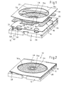
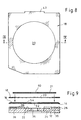
- a holder for use in a machine for decorating or printing on articles, for holding such an article which substantially comprises a base member 12 in the general form of a plate, an intermediate plate 14 which rests on the base member 12 and to the surface of which, that is remote from the base member 12, there is fitted a multi-part adhesive film 16 forming a layer of soft material, and a format plate 18 provided with an opening 20 in the form of a round hole in this embodiment, the shape and size of the opening 20 being suitably matched to the shape and size of an article to be decorated as indicated at 21 in Figure 9.
- the film 16 in the form of a layer of soft material is of such a softness as to serve the purposes referred to hereinbefore, namely suitably supporting the article 21 which rests thereon for the decoration procedure while being sufficiently soft to allow particles such as dust and the like which come between the layer of soft material and the article resting thereon to be suitably pressed into the film so that the article will not be damaged as by scratching.
- the upper boundary surface of the base member 12, as indicated at 22 in Figure 3, is of a substantially flat nature so that the lower boundary surface of the intermediate plate 14, which is also flat, bears closely and snugly on the upper surface 22 of the base member 12.
- Two first magnets 24 are let into the base member 12 in such a way that their surfaces which face towards the intermediate plate 14 are aligned with the upper surface 22 of the base member 12.
- the intermediate plate 14 which comprises magnetisable material is held in position by the two permanent magnets 24.
- the base member 12 In order for easily determining the position of the intermediate plate 14 on the base member 12, the base member 12, at one of its two lateral boundaries which is shorter than the other two lateral boundaries extending perpendicularly thereto, is provided with a bar-shaped projection 26 which projects upwardly with respect to the upper surface 22 of the base member 12 and which has an opening as indicated at 28 in Figure 3, into which a tongue-shaped projection indicated at 30 in Figure 6 on the intermediate plate 14 engages when the intermediate plate 14 assumes its desired or reference position on the base member 12, that position being characterised inter alia by a central opening 32 in the intermediate plate 14 being aligned with a corresponding opening 34 in the base member 12.
- the tongue-like projection 30 is of such a size that it engages with a close fit into the opening 28 in the bar-shaped projection 26.
- the base member 12 is further provided with four second magnets which can be most clearly seen at 36 in Figure 3 but which project beyond the upper surface 22 of the base member 12 by a distance which is approximately the same as the thickness of the intermediate plate 14 with the film 16 adhering thereto.
- the magnets 36 engage into holes shown at 38 in Figure 1 in the intermediate plate 14 and recesses shown at 39 in Figure 1 in the film 16, in such a way that the upper boundary surfaces designated by references 40 in Figure 7 on the magnets 36 approximately align with the upper surface of the film 16 which is fixed by adhesive on the intermediate plate 14.
- the format plate 18 which also comprises magnetisable material rests on the film 16 and the second magnets 36 and is held in position by the latter.
- the format plate 18 is also provided with a tongue-shaped projection designated by reference 42 in Figure 8 which, similarly to the projection 30 on the intermediate plate 14, also extends in the plane of the respective plate. Also similarly to the projection 30 on the intermediate plate 14, the projection 42 on the format plate 18 engages with a close fit into the opening 28 in the bar-shaped projection 26 in order thereby to fix the position of the format plate 18 relative to the base member 12 and relative to the intermediate plate 14.
- the format plate 18 in the embodiment illustrated herein is flat at top and bottom thereof.
- the film 16 has three further portions as shown at 16b, 16c and 16d in Figure 6.
- the central portion 16a on the one hand and the other two portions 16b, 16c on the other hand are separated from each other by a substantially annular opening indicated at 46 in Figure 6.
- the opening 46 is arranged in such a way that, when the holder 10 is assembled, the opening 46 extends along the boundary of the opening 20 in the format plate 18 and thus substantially along the outer periphery of an article 21 accommodated in the receiving means 44.
- the opening 46 with the upper boundary surface 48, forms a groove 50 which, for example in the case of a round CD disposed in the receiving means 44, extends substantially along the peripheral edge of the CD, which edge, particularly in the case of a CD produced by means of injection molding, may have sharp-edged projections, burrs or the like which, if a film were also arranged in the region of the groove 50, could damage same.
- the groove corresponding to the opening 46 thus represents a free space into which sharp-edged projections, burrs or the like of that kind can project without involving the risk of damage to any parts, more particularly the film 16, the central portion of which terminates at the inner periphery of the groove 50.
- the two portions 16b and 16c of the film 16, which are outside the opening 46, are disposed, when the holder 10 is in the assembled condition, between the corresponding regions of the intermediate plate 14 and the format plate 18 respectively, that is to say outside the opening 20 provided in the latter. That affords the advantage that the format plate 18 which rests on the regions 14b, 14c of the film 16 is also displaced upwardly by the dimension corresponding to the thickness of the adhesive film 16 so that the presence of the film means that there is no change whatsoever in terms of the relationship between the position of the format plate on the one hand and the article in the receiving means 44 on the other hand. Both those parts, namely the article and the format plate, are arranged displaced upwardly by the thickness of the adhesive film 16.
- the thickness of the film 16 can be for example 0.35 mm.
- the above-described arrangement of the component parts makes it possible to use an intermediate plate which is flat at both sides and which is thus simple in terms of structure and also manufacture, wherein the intermediate plate can be of a thickness of for example 1.0 mm.
- the film 16 is provided with a further peripherally extending annular opening as indicated at 54 for example in Figures 2 and 3.
- the opening 54 together with the corresponding annular portion of the boundary surface 48 of the intermediate plate 14, forms a groove or depression. That annular depression which is thus defined by the central film portion 16a and the film ring 16d delimiting the central hole 52 can accommodate if appropriate any projections which may be found on the article to be accommodated in the receiving means 44 and which serve for example as a spacer so that the article is not prevented from resting snugly and closely on the film portions 16a and 16d in the remaining region of the receiving means 44.
- the intermediate plate 14 can be provided along the annular opening 54 with a groove-shaped depression if the dimensions of the projections on the articles require that.
- reference 56 denotes passages which communicate with the depression formed by the annular opening 54 and the upper surface 48 of the intermediate plate 14.
- the passages 56 can be communicated with a suitable reduced-pressure source by way of further passages indicated at 57 in Figure 3, in the base member 12.
- the reduced pressure which thereby acts on an article in the receiving means 44 provides that the article is secured in position for example during transportation thereof in the holder 10 through treatment stations of a machine for decorating or applying printing to the article, after the article has been previously properly aligned for example in the station in which the article was introduced into the decorating or printing machine or in a subsequent station, the alignment procedure being implemented by a centering bar which will have been introduced through the opening 34 in the base member 12, the opening 32 in the intermediate plate 14, the central opening in the film 16 and the opening 60 in the article 21 itself.
- the central film portion 16a which fills up the substantial part of the receiving means 44 and the film ring 16d which extends around the central opening 52, in particular by virtue of their elastic flexibility, in conjunction with the lower surface of the article which rests on the film portions, provide for a sealing effect in respect of the groove-shaped depression defined by the opening 54, so that the reduced pressure which acts on the article to secure it in place can be maintained without causing any real difficulty.
- the arrangement is such that the format plate 18 is of smaller thickness than the article such as the CD 21 so that the surface of the article which is to be decorated or printed upon is disposed at a higher level than the upward surface of the format plate 18 so that, when using for example offset printing, there is no danger of the impression cylinder coming into contact with the upper surface of the format plate 18.
- the thickness of the format plate 18 can be for example 0.6 mm.
- the operation of fitting the adhesive film 16, which in this embodiment comprises a plurality of portions, to the intermediate plate 14, can be effected in a simple manner by a procedure whereby the portions of the adhesive film 16 are arranged on a carrier or backing film, in the relationships corresponding to their subsequent arrangement on the intermediate plate 14, so that the portions of the self-adhesive film 16 can then be transferred from the carrier film on to the intermediate plate in the usual way in a single working operation.
- the eccentric member 58 the thickness of which approximately corresponds to the total thickness of the intermediate plate 14, the adhesive film 16 thereon and the format plate 18, is arranged in such a way that, in a given angular position about its axis of rotation, it bears against the lateral inclined edge surface 62 of the intermediate plate 14 and clamps it in its position as determined by the two bar projections 26 at the opposite side of the base member 12.
- the arrangement here is such that in this case there is a small amount of play between the eccentric member 58 and the format plate 18, such play on the one hand ensuring that the format plate does not become jammed, while on the other hand permitting it only a quite small freedom of motion, if any at all, which in any case can be only minimal by virtue of the positively locking connection afforded between the format plate 18 and the bar-shaped projection 26.
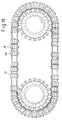
- FIG. 10 showing in highly diagrammatic form the structure of an embodiment of a machine for decorating or applying printing to articles by means of screen printing and offset printing, although the printing stations are not shown for the sake of enhanced clarity of the drawing.
- the illustrated machine is provided with more than thirty holders 10 as described hereinbefore, which are suitable in particular for CDs and which circulate through the respective stations of the machine on an endless conveyor belt.
- the holder according to the invention has an additional intermediate plate which if necessary can be removed from the holder in order to fit the intermediate plate with a fresh layer of soft material, in which respect the operation of removing the used or worn layer from the intermediate plate 18 and the operation of fitting a fresh layer to the intermediate plate 18 can be implemented outside the machine so that operation of the machine normally remains unaffected by the procedure for replacing the layer of soft material, if the format plate has to be replaced in any case.
- the amount of time required for replacing the layer of soft material is negligible if two intermediate plates 18 are kept available for each holder, and they can thus be used in alternate succession.
- the operation of changing the layer of soft material in the form of the film 16 can be implemented in an extremely short period of time if an intermediate plate 18 with the fresh layer of soft material thereon is already available and ready for fitment at the time of the change procedure being effected. In that case at least two intermediate plates 18 would be required for each holder. It will be appreciated however that the increase in expenditure that this entails is very low as the intermediate plates 18 can be simple sheet metal portions which are inexpensive to manufacture so that, even in the case of printing machines and decorating machines and the like which have numerous holders, a considerable economic advantage is still at any event achieved by virtue of the reduction in machine stoppage times.
- the invention still affords the advantage of simplicity of operation in terms of changing the layer of soft material for supporting an article in each holder, as it will normally be easier for the operations which are linked to changing the layers of soft material, that is to say removing the film 16 to be replaced, cleaning residues of adhesive off the intermediate plate 18 and fitting a new film 16 to the cleaned intermediate plate 18, to be implemented when the holder is out of the machine, than on a holder which is still fitted in the machine.
Landscapes
- Engineering & Computer Science (AREA)
- Mechanical Engineering (AREA)
- Labeling Devices (AREA)
Description
Claims (20)
- A holder for use in a machine for decorating articles for holding a said article, the holder (10) comprising
a base member (12),
a format plate (18) arranged releasably over the base member and having an opening for receiving an article,
an intermediate plate (14) arranged releasably between the base member and the format plate and having a surface remote from the base member, and
a thin layer of a soft material (16) for supporting the article thereon, said layer being mounted to said remote surface of said intermediate plate. - A holder as set forth in claim 1
wherein said layer is a flexible film on the intermediate plate. - A holder as set forth in claim 1 ,
wherein said layer is glued to the intermediate plate. - A holder as set forth in claim 1
wherein said layer is elastically yielding. - A holder as set forth in claim 1
wherein said layer comprises plastic material. - A holder as set forth in claim 5
wherein said plastic material is polyurethane. - A holder as set forth in claim 1 including
first magnet means on the base member for holding the intermediate plate to the base member. - A holder as set forth in claim 1 and further including
second magnet means on the base member,
wherein the intermediate plate has openings through which said second magnet means extend for holding the format plate to the intermediate plate. - A holder as set forth in claim 8
wherein said layer is provided with openings through which the second magnet means extend. - A holder as set forth in claim 7
wherein said layer is provided with recesses through which the second magnet means extend. - A holder as set forth in claim 1
wherein said layer comprises a plurality of portions including at least a central portion associated with the region defined by the opening in the format plate and at least one further portion between the intermediate plate and the format plate. - A holder as set forth in claim 11
wherein the central portion of said layer is subdivided in such a way that a first annular disk of soft material is arranged in concentric relationship with a central hole in the intermediate plate, the first annular disk being surrounded by a wider second annular disk of soft material in concentric relationship with the first annular disk, leaving an annular spacing from the first annular disk. - A holder as set forth in claim 12
wherein the second annular disk terminates at a small spacing from the outer boundary of the article-receiving means delimited by the opening in the format plate, in such a way that along the outer periphery of said receiving means there is an annular surface not covered by said layer. - A holder as set forth in claim 1
wherein the base member and the intermediate plate are each provided with at least one hole and said holes are in at least partially mutually overlapping relationship and are connectable through the hole in the base member to a reduced-pressure source. - A holder as set forth in claim 14
wherein said at least one hole in the intermediate plate at the side thereof remote from the base member opens in the non-covered region of the intermediate plate between the first annular disk and the second annular disk. - A holder as set forth in claim 1 including
a means for fixing the intermediate plate in its operative position. - A holder as set forth in claim 16
wherein the means for fixing the intermediate plate in its operative position includes on the base member a displaceable element which in an operative position thereof clamps the intermediate plate in its said operative position. - A holder as set forth in claim 17
wherein said displaceable element comprises an eccentric carried by the base member and rotatable about an axis perpendicular to the main plane of the base member, the eccentric in its operative position bearing against the intermediate plate for clamping it in its operative position. - Method of renewing the layer for supporting the article thereon of the holder according to claim 1, the method including
removing the intermediate plate (14) with said layer of a soft material (16) to be renewed from the holder (10) and
fitting an intermediate plate (14) with a new said layer (16) in the holder (10). - Apparatus for decorating articles including
at least one holder as set forth in claim 1.
Applications Claiming Priority (2)
| Application Number | Priority Date | Filing Date | Title |
|---|---|---|---|
| DE10239391A DE10239391B4 (en) | 2002-08-28 | 2002-08-28 | Holder for an object to be decorated |
| DE10239391 | 2002-08-28 |
Publications (2)
| Publication Number | Publication Date |
|---|---|
| EP1393902A1 EP1393902A1 (en) | 2004-03-03 |
| EP1393902B1 true EP1393902B1 (en) | 2004-12-15 |
Family
ID=31197442
Family Applications (1)
| Application Number | Title | Priority Date | Filing Date |
|---|---|---|---|
| EP03015140A Expired - Lifetime EP1393902B1 (en) | 2002-08-28 | 2003-07-04 | Holder for an article to be decorated |
Country Status (4)
| Country | Link |
|---|---|
| US (1) | US6820553B2 (en) |
| EP (1) | EP1393902B1 (en) |
| DE (2) | DE10239391B4 (en) |
| PL (1) | PL361829A1 (en) |
Families Citing this family (8)
| Publication number | Priority date | Publication date | Assignee | Title |
|---|---|---|---|---|
| US20040195465A1 (en) * | 2003-04-04 | 2004-10-07 | Alain Crouan | CD case support method and apparatus |
| US7134391B2 (en) * | 2004-07-22 | 2006-11-14 | Northrop Grumman Corporation | Apparatus and method for side printing on low temperature co-fired ceramic (LTCC) substrates |
| DE102006023111A1 (en) * | 2006-05-16 | 2007-11-22 | Werner Kammann Maschinenfabrik Gmbh & Co. Kg | Device for coating objects |
| US20080236413A1 (en) * | 2007-03-30 | 2008-10-02 | Castleberry Jeffrey G | Media carrier |
| US8366946B2 (en) * | 2009-08-28 | 2013-02-05 | United States Of America As Represented By The Secretary Of The Navy | Frame for holding laminate during processing |
| CN109050011B (en) * | 2018-10-19 | 2024-02-20 | 张家港市联盛塑业有限公司 | Multifunctional ink jet device for plastic products |
| KR20240139105A (en) * | 2023-03-08 | 2024-09-23 | 삼성디스플레이 주식회사 | Apparatus for printing, method for manufacturing window member using the same, and display device including window member manufactured using the same |
| WO2025083645A1 (en) * | 2023-10-20 | 2025-04-24 | 2360216 Ontario Inc. | Trigger device for bolt action firearm |
Family Cites Families (12)
| Publication number | Priority date | Publication date | Assignee | Title |
|---|---|---|---|---|
| US5429045A (en) * | 1992-11-12 | 1995-07-04 | Karlyn; William M. | Means for registering a compact disc for the silk-screen printing thereof |
| US5609102A (en) * | 1995-01-17 | 1997-03-11 | Autoroll Machine Corporation | Fixture for holding a compact disc to be silk-screen printed |
| DE19614740A1 (en) * | 1996-04-15 | 1997-10-16 | Kammann Maschf Werner | Method and device for printing self-supporting individual objects |
| US5682817A (en) * | 1996-07-01 | 1997-11-04 | Sony Corporation | Quick removing compact disc printing nest |
| US5797688A (en) * | 1997-01-07 | 1998-08-25 | Eastman Kodak Company | Thermal dye transfer printing of compact disc labels including a circular recessed carrier |
| DE19745313A1 (en) * | 1997-10-14 | 1999-04-15 | Kammann Maschf Werner | Device and method for decorating objects |
| DE19810128C2 (en) * | 1998-03-09 | 2000-09-21 | Thomas Meyer | Printing tool for holding data media to be printed |
| US6312174B1 (en) * | 1998-11-13 | 2001-11-06 | Wordtech Systems, Inc. | Thermal printer for compact disks |
| US6630231B2 (en) * | 1999-02-05 | 2003-10-07 | 3M Innovative Properties Company | Composite articles reinforced with highly oriented microfibers |
| EP1260377B1 (en) * | 2001-05-14 | 2006-02-15 | Alps Electric Co., Ltd. | Intermediate transfer type printer equipped with mounting tray for mounting recording medium |
| EP1660145A2 (en) * | 2003-08-13 | 2006-05-31 | Medtronic, Inc. | Active agent delivery systems, including a single layer of a miscible polymer blend, medical devices and methods |
| US20050064005A1 (en) * | 2003-08-13 | 2005-03-24 | Dinh Thomas Q. | Active agent delivery systems including a miscible polymer blend, medical devices, and methods |
-
2002
- 2002-08-28 DE DE10239391A patent/DE10239391B4/en not_active Expired - Fee Related
-
2003
- 2003-07-04 DE DE60300215T patent/DE60300215T2/en not_active Expired - Fee Related
- 2003-07-04 EP EP03015140A patent/EP1393902B1/en not_active Expired - Lifetime
- 2003-08-13 US US10/640,070 patent/US6820553B2/en not_active Expired - Fee Related
- 2003-08-25 PL PL03361829A patent/PL361829A1/en not_active IP Right Cessation
Also Published As
| Publication number | Publication date |
|---|---|
| US6820553B2 (en) | 2004-11-23 |
| EP1393902A1 (en) | 2004-03-03 |
| DE10239391B4 (en) | 2004-11-25 |
| DE60300215D1 (en) | 2005-01-20 |
| US20040040453A1 (en) | 2004-03-04 |
| PL361829A1 (en) | 2004-03-08 |
| DE60300215T2 (en) | 2006-03-02 |
| DE10239391A1 (en) | 2004-03-25 |
Similar Documents
| Publication | Publication Date | Title |
|---|---|---|
| US6820553B2 (en) | Holder for an article to be decorated | |
| JP4257497B2 (en) | Vacuum deposition method, vacuum deposition apparatus, and EL panel manufactured by this vacuum deposition method | |
| KR101755282B1 (en) | Sub plate for polishing pad and method of recovering polishing pad using the same | |
| EP1208941A3 (en) | Method and machine for grinding coated sheets of glass | |
| WO2001000493A1 (en) | Plastic container for the transportation and/or storage of goods | |
| JP2018199177A (en) | Sintered magnet cutting processor and cutting processing method | |
| EP0797510B1 (en) | Doctoring ink cup | |
| JP4270142B2 (en) | Method and apparatus for manufacturing glass substrate | |
| EP1006006B1 (en) | System for carrying engraveable workpieces of different configurations | |
| US12168541B2 (en) | Label holder with magnetic suction plate | |
| KR101074141B1 (en) | A roller for transferring labels | |
| US10049696B2 (en) | Optical recording medium production device and production method | |
| WO2007069023A2 (en) | Pad printing machine | |
| JP2005161512A (en) | Plate type work polishing device | |
| JP2858255B2 (en) | Pad printing equipment | |
| US5682817A (en) | Quick removing compact disc printing nest | |
| CN223267107U (en) | Electronic component positioning and placement device | |
| KR101836233B1 (en) | Polishing pad recovering method using sub plate for polishing pad | |
| JPH05311441A (en) | Apparatus for producing magneto-optical disk | |
| KR101869476B1 (en) | In-mold forming method | |
| JPH09155729A (en) | Flat polishing plate and flat polishing apparatus using the same | |
| JP2011108928A (en) | Substrate supporting device, vacuum processing apparatus, and holder cover | |
| KR20030069084A (en) | Magnetic transfer apparatus | |
| JPH03225644A (en) | Disk substrate manufacturing instrument | |
| JP2006310616A (en) | Manufacturing method of stationary carrier |
Legal Events
| Date | Code | Title | Description |
|---|---|---|---|
| PUAI | Public reference made under article 153(3) epc to a published international application that has entered the european phase |
Free format text: ORIGINAL CODE: 0009012 |
|
| AK | Designated contracting states |
Kind code of ref document: A1 Designated state(s): AT BE BG CH CY CZ DE DK EE ES FI FR GB GR HU IE IT LI LU MC NL PT RO SE SI SK TR |
|
| AX | Request for extension of the european patent |
Extension state: AL LT LV MK |
|
| 17P | Request for examination filed |
Effective date: 20040205 |
|
| GRAP | Despatch of communication of intention to grant a patent |
Free format text: ORIGINAL CODE: EPIDOSNIGR1 |
|
| GRAS | Grant fee paid |
Free format text: ORIGINAL CODE: EPIDOSNIGR3 |
|
| GRAA | (expected) grant |
Free format text: ORIGINAL CODE: 0009210 |
|
| AKX | Designation fees paid |
Designated state(s): DE FR GB IT |
|
| AK | Designated contracting states |
Kind code of ref document: B1 Designated state(s): DE FR GB IT |
|
| PG25 | Lapsed in a contracting state [announced via postgrant information from national office to epo] |
Ref country code: IT Free format text: LAPSE BECAUSE OF FAILURE TO SUBMIT A TRANSLATION OF THE DESCRIPTION OR TO PAY THE FEE WITHIN THE PRESCRIBED TIME-LIMIT;WARNING: LAPSES OF ITALIAN PATENTS WITH EFFECTIVE DATE BEFORE 2007 MAY HAVE OCCURRED AT ANY TIME BEFORE 2007. THE CORRECT EFFECTIVE DATE MAY BE DIFFERENT FROM THE ONE RECORDED. Effective date: 20041215 |
|
| REG | Reference to a national code |
Ref country code: GB Ref legal event code: FG4D |
|
| REG | Reference to a national code |
Ref country code: IE Ref legal event code: FG4D |
|
| REF | Corresponds to: |
Ref document number: 60300215 Country of ref document: DE Date of ref document: 20050120 Kind code of ref document: P |
|
| RAP2 | Party data changed (patent owner data changed or rights of a patent transferred) |
Owner name: WERNER KAMMANN MASCHINENFABRIK GMBH & CO. KG |
|
| PLBE | No opposition filed within time limit |
Free format text: ORIGINAL CODE: 0009261 |
|
| STAA | Information on the status of an ep patent application or granted ep patent |
Free format text: STATUS: NO OPPOSITION FILED WITHIN TIME LIMIT |
|
| 26N | No opposition filed |
Effective date: 20050916 |
|
| ET | Fr: translation filed | ||
| GBPC | Gb: european patent ceased through non-payment of renewal fee |
Effective date: 20070704 |
|
| PG25 | Lapsed in a contracting state [announced via postgrant information from national office to epo] |
Ref country code: GB Free format text: LAPSE BECAUSE OF NON-PAYMENT OF DUE FEES Effective date: 20070704 |
|
| PGFP | Annual fee paid to national office [announced via postgrant information from national office to epo] |
Ref country code: FR Payment date: 20090720 Year of fee payment: 7 |
|
| PGFP | Annual fee paid to national office [announced via postgrant information from national office to epo] |
Ref country code: DE Payment date: 20090924 Year of fee payment: 7 |
|
| REG | Reference to a national code |
Ref country code: FR Ref legal event code: ST Effective date: 20110331 |
|
| PG25 | Lapsed in a contracting state [announced via postgrant information from national office to epo] |
Ref country code: DE Free format text: LAPSE BECAUSE OF NON-PAYMENT OF DUE FEES Effective date: 20110201 |
|
| REG | Reference to a national code |
Ref country code: DE Ref legal event code: R119 Ref document number: 60300215 Country of ref document: DE Effective date: 20110201 |
|
| PG25 | Lapsed in a contracting state [announced via postgrant information from national office to epo] |
Ref country code: FR Free format text: LAPSE BECAUSE OF NON-PAYMENT OF DUE FEES Effective date: 20100802 |