EP1393867A1 - Two-leg walking humanoid robot - Google Patents
Two-leg walking humanoid robot Download PDFInfo
- Publication number
- EP1393867A1 EP1393867A1 EP02733274A EP02733274A EP1393867A1 EP 1393867 A1 EP1393867 A1 EP 1393867A1 EP 02733274 A EP02733274 A EP 02733274A EP 02733274 A EP02733274 A EP 02733274A EP 1393867 A1 EP1393867 A1 EP 1393867A1
- Authority
- EP
- European Patent Office
- Prior art keywords
- robot
- leg
- attached
- movable relative
- pivotally movable
- Prior art date
- Legal status (The legal status is an assumption and is not a legal conclusion. Google has not performed a legal analysis and makes no representation as to the accuracy of the status listed.)
- Granted
Links
Images




Classifications
-
- B—PERFORMING OPERATIONS; TRANSPORTING
- B62—LAND VEHICLES FOR TRAVELLING OTHERWISE THAN ON RAILS
- B62D—MOTOR VEHICLES; TRAILERS
- B62D57/00—Vehicles characterised by having other propulsion or other ground- engaging means than wheels or endless track, alone or in addition to wheels or endless track
- B62D57/02—Vehicles characterised by having other propulsion or other ground- engaging means than wheels or endless track, alone or in addition to wheels or endless track with ground-engaging propulsion means, e.g. walking members
- B62D57/032—Vehicles characterised by having other propulsion or other ground- engaging means than wheels or endless track, alone or in addition to wheels or endless track with ground-engaging propulsion means, e.g. walking members with alternately or sequentially lifted supporting base and legs; with alternately or sequentially lifted feet or skid
-
- B—PERFORMING OPERATIONS; TRANSPORTING
- B25—HAND TOOLS; PORTABLE POWER-DRIVEN TOOLS; MANIPULATORS
- B25J—MANIPULATORS; CHAMBERS PROVIDED WITH MANIPULATION DEVICES
- B25J5/00—Manipulators mounted on wheels or on carriages
-
- B—PERFORMING OPERATIONS; TRANSPORTING
- B25—HAND TOOLS; PORTABLE POWER-DRIVEN TOOLS; MANIPULATORS
- B25J—MANIPULATORS; CHAMBERS PROVIDED WITH MANIPULATION DEVICES
- B25J13/00—Controls for manipulators
- B25J13/08—Controls for manipulators by means of sensing devices, e.g. viewing or touching devices
- B25J13/081—Touching devices, e.g. pressure-sensitive
-
- B—PERFORMING OPERATIONS; TRANSPORTING
- B25—HAND TOOLS; PORTABLE POWER-DRIVEN TOOLS; MANIPULATORS
- B25J—MANIPULATORS; CHAMBERS PROVIDED WITH MANIPULATION DEVICES
- B25J19/00—Accessories fitted to manipulators, e.g. for monitoring, for viewing; Safety devices combined with or specially adapted for use in connection with manipulators
- B25J19/0091—Shock absorbers
Definitions
- the present invention relates to a biped (two-footed) walking humanoid robot and, in particular, to a biped walking humanoid robot which is so designed that shocks acting on various parts of the robot when it falls can be relieved and its state or type of fall can then be detected.
- a biped walking robot as it is called in the art has so far been made able to walk with two legs by producing in advance data for a preestablished walking pattern (hereinafter referred to as "gait") and actuating the legs in a controlled manner in accordance with the gait data so that the robot can bipedally walk as desired.
- gait a preestablished walking pattern
- Such a conventional biped walking robot tends to become unstable in walking position due, for example, to floor or ground surface conditions and an error in the physical parameters of the robot itself and may then even turn over or fall violently.
- a biped walking humanoid robot which includes a body portion having an upper and a lower part, a pair of leg portions attached to the lower part of the body portion at a pair of its opposite sides, respectively, a pair of arm portions attached to the upper part of the body portion at a pair of its opposite sides, respectively, and a head portion attached to an upper end of the upper part of the body portion, wherein each of the leg portions includes tow upper leg portions attached to the lower part of the body portion so as to be pivotally movable relative thereto triaxially, a lower leg portion attached to the upper leg portion so as to be pivotally movable relative thereto monoaxially, and a foot portion attached to the lower leg portion so as to be pivotally movable relative thereto biaxially, wherein each of the arm portions includes two upper arm portions attached to the upper part of the body portion so as to be pivotally movable relative thereto biaxially, a lower arm portion attached to the upper arm
- a biped walking humanoid robot according to the present invention is preferably so configured in each of such contact detectors that the said pressure sensor and the said impact absorbing material are integrally formed and more preferably that the said casing portion, the said pressure sensor and the said impact absorbing material are formed integrally.
- a biped walking humanoid robot according to the present invention is also preferably so configured in each of such contact detectors that the said casing portion lies at an outermost side thereof, or that the said pressure sensor lies at an outermost side thereof, or that the said impact absorbing material lies at an outermost side thereof.
- a biped walking humanoid robot is preferably so configured that each of the aid body portion, the upper and lower arm portions of the said arm portions, and the upper and lower leg portions of the said leg portions has a curved outer covering surface that is convex in contour.
- a biped walking humanoid robot is preferably so configured that for each of the said leg portions, the said foot portion is made pivotally movable relative to the said lower leg portion in a pitch direction in a range of angles from -20 to +20 degrees or more, the said lower leg portion is made pivotally movable relative to the said upper leg portion in a pitch direction in an range of angles from 0 to +60 degrees or more, and the said upper leg portion is made pivotally movable relative to said body portion in a pitch direction in a range of angles from 0 to +45 degrees or more, and the said body portion is made able to bend forward in a range of angles from 0 to +30 degrees or more.
- a biped walking humanoid robot is preferably so configured that those of the said drive means for pivotally moving the foot portion, the lower leg portion and the upper leg portion of each of the said leg portions, respectively, are disposed inclined to one another so as not to hinder pivotal movements of the said foot portion, the said upper portion and the said lower leg portions.
- any shock acting on any of these parts hitting on the floor or ground can be absorbed by the impact absorbing material.
- the state or type of this fall can be determined by the control means in response to a contact signal detected by the pressure sensor in the contact detector at a relevant part of the abovementioned robot parts which is brought into contact with the floor or ground. Then, on the basis of the type of the fall determined, the control means is allowed to act on the drive means to move the arm and leg parts suitably so as to cause the robot to take a corrective falling action to have a safety fall and then to move to taking a rising action to get up on its feet.
- each contact detector Forming integrally the pressure sensor and the impact absorbing material, or the casing portion, the pressure sensor and the impact absorbing material, in each of the contact detectors allows each contact detector to be simplified in makeup and to be readily assembled.
- disposing the casing portion at the outermost side is advantageous in that when the biped walking humanoid robot falls to cause the contact detector to hit on the floor or ground, the casing comes into direct contact with the floor or ground, thereby protecting the pressure sensor, the impact resistant material and further the inner structure of the robot from the shock.
- disposing the pressure sensor at the outermost side is advantageous in that when the biped walking humanoid robot falls, the pressure sensor comes into direct contact with the floor or ground, thereby making most certain of sensing the pressure contact of the contact detector with the floor or ground.
- each contact detector disposing the impact absorbing material at the innermost side is advantageous in that when the biped walking humanoid robot falls to cause the contact detector to hit on the floor or ground, the impact absorbing material comes into direct contact with the floor or ground, thereby making for most certain of absorbing the shock.
- the foot portion is made pivotally movable relative to the lower leg portion in a pitch direction in a range of angles between -20 and +20 degrees
- the lower leg portion is made pivotally movable relative to the upper leg portion in a pitch direction in an range of angles between 0 and +60 degrees
- the upper leg portion is made pivotally movable relative to body portion in a pitch direction in a range of angles between 0 and +45 degrees
- the body portion is made able to bend forward in a range of angles between 0 and +30 degrees
- the biped humanoid robot in its rising action from the state of a fall is allowed to rise for certain by virtue of the fact that the foot portion, the lower leg portion and the upper leg portion of each of the leg portions are prevented in their respective pivotal movements from interfering with one another.
- Figs. 1 and 2 show how a biped walking humanoid robot according to the present invention is constructed in one form of implementation thereof.
- the biped walking robot indicated by reference character 10 includes a trunk 11 having a pair of legs 12L and 12R attached to its lower part 11b at a pair of opposite sides thereof, respectively, a pair of arms 13L and 13R attached to its upper part 11 a at a pair of opposite sides thereof, respectively, and a head 14 attached to its upper end.
- An anteflex region 11c separates the upper and lower parts 11a and 11b of the trunk 11 from each other.
- the upper trunk part 11a is supported pivotally at the anteflex region 11c so as to be able to swing forth and back and especially to be able to bend forward.
- the trunk 11 contains a control means to be described later, and the anteflex region 11c is constituted by a joint drive motor in such motors shown in and to be described in connection with Fig. 2.
- Each of the legs 12L and 12R is made of an upper leg 15L, 15R, a lower leg 16L, 16R, and a foot 17L, 17R.
- each of the legs 12L and 12R as shown in Fig. 2 has six (6) joint regions, namely stated in turn from upside, a waist joint region 18L, 18R for turning (pivotally moving) the corresponding leg 12L, 12R relative to the trunk 11, a first hip joint region 19L, 19R for turning the leg about a roll x-axis.
- a second hip joint region 20L, 20R for turning the leg about a pitch y-axis
- a second ankle joint region 24L, 24R for turning the foot 17L, 17R about a roll axis.
- Each of these joint regions 18L, 18R ⁇ 24L, 24R is constituted as and by a joint drive motor. It follows, therefore, that the waist/hip joints are constituted by the joints 18L, 18R, 19L, 19R and 20L, 20R while the foot joints are by the joints 23L, 23R and 24L, 24R.
- This makeup provides the six (6) degrees of freedom for each of the left and right hand side legs 12L, 12R of the biped walking humanoid robot 10.
- the robot 10 is thus so configured that if these twelve (12) joint regions are adapted to be driven by the respective drive motors in a controlled manner to make proper angular movements such as to move the legs 12L and 12R properly as a whole, the robot is rendered capable of walking in any way as desired in a three-dimensional space.
- Each of the arms 13L and 13R is made of an upper arm 25L, 25R, a lower arm 26L, 26R and a hand 27L, 27R.
- the upper arm 25L, 25R, the lower arm 26L, 26R and the hand 27L, 27R are each made pivotally movable monoaxially or biaxially as in each of the legs 12L and 12R.
- Each of the joint regions is constituted as and by a joint drive motor. Given appropriate degrees of freedom in this manner, each of the left and right hand arms 13L and 13R of the biped walking humanoid robot 10 is made movable as desired.
- the head 14 which is mounted to the upper end of the upper trunk part 11a of the trunk body 11 is provided with a camera for vision and a microphone for audition.
- the biped walking humanoid robot 10 of the invention constructed as mentioned above is essentially the same in makeup as the conventional biped walking humanoid robot but is novel and unique in makeup as mentioned below.
- each of the upper and lower trunk parts I 1a and I 1b of the trunk body 11, the upper legs 15L and 15R and the lower legs 16L and 16R of the legs 12L and 12R, and the upper arms 25L and 25R and the lower arms 26L and 26R of the arms 13L and 13R has a curved outer covering surface area that is convex or bulged in outline as shown in Fig. I and formed of an impact resistant material such as, for instance, styrofoam.
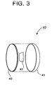
- the contact detector 40 as shown in Fig. 3 comprises an outer casing portion 41 of a material that constitutes the outer covering surface areas of the robot mentioned above, a pressure sensor 42 disposed inwards of the outer covering portion 41 and an impact absorbing material 43 disposed interiorly of the pressure sensor 42.
- Such outer covering portions 41 are convex in contour and formed of an impact resistant material such as, for instance, styrofoam as are the surface areas of the other parts of the robot mentioned above.
- the pressure sensor 42 when the biped walking humanoid robot 10 falls down or over is adapted to sense a contact pressure produced upon the corresponding contact detector 40 forcibly coming into contact with the floor or ground to provide a contact sensing signal for the control means or stage to be described later.
- the impact absorbing material made, e. g., of sorbothane is designed to absorb a shock which that contact detector 40 may receive from the floor or ground when the biped walking humanoid robot 10 falls down or over.
- the contact detector 40 is shown comprising, from outer to inner, the covering or casing portion 41, the pressure sensor 42 and the impact absorbing material 42, they may be arranged in any order as desired.
- disposing the casing portion 41 at the outermost side is advantageous in that when the biped walking humanoid robot 10 falls to cause the contact detector 40 to hit on the floor or ground, the casing 41 comes into direct contact with the floor or ground, thereby protecting the pressure sensor 42, the impact resistant material 43 and further the inner structure of the robot from the shock.
- Disposing the pressure sensor 42 at the outermost side is advantageous in that when the biped walking humanoid robot 10 falls, the pressure sensor 42 comes into direct contact with the floor or ground, thereby making most certain of sensing the pressure contact of the contact detector 40 with the floor or ground.
- Disposing the impact absorbing material 43 at the innermost side is advantageous in that when the biped walking humanoid robot 10 falls to cause the contact detector 40 to hit on the floor or ground, the impact absorbing material comes into direct contact with the floor or ground, thereby making for most certain of absorbing the shock.
- the contact detector 40 is shown comprising the casing portion 41, the pressure sensor 42 and the impact absorbing material each separate from another, the casing portion 42 and the impact absorbing material, or the casing portion 41, the pressure sensor 42 and the impact absorbing material 43 may be made integral.
- the anteflex region 11c of the trunk body 11 and the joints front side back in the legs 12L and 12R namely the hip joints 20L and 20R, the knee joints 22L and 22R and the ankle joints 23L and 23R are individually made pivotable within angular limits as shown in Figs. 4 and 5.
- the ankle joints 23L and 23R are each made pivotable in a rage of angles ⁇ 1 from -20 to +20 degrees.
- the knee joints 22L and 22R are each made pivotable in a range of angles ⁇ 2 from 0 to +60 degrees.
- the hip joints 20L and 20R are each made pivotable in a range of angles ⁇ 3 of 0 to +45 degrees.
- the anteflex region 11c of the trunk body 11 is each made pivotable in a range of angles ⁇ 4 from 0 to +30 degrees.
- joint drive motors are provided for the anteflex region 11c and the joints 20L, 20R, 22L, 22R, 23L and 23R and arranged as shown in Fig. 6. Referring to Fig. 6,
- the joint drive motors M2, M3 and M4 for the anteflex region 11c and the joints 20L, 20R, 22L, 22R, 23L and 23R have their respective drive shafts coupled via reducers G2, G3 and G4 to their output shafts G2a, G3a and G4a so as to drive the anteflex region 11c and the joints 20L, 20R, 22L, 22R, 23L and 23R, thereby swinging or pivotally moving the upper trunk 11a of the trunk body, 11, the upper legs 15L and 15R, the lower legs 16L and 16R and the feet 17L and 17R about them, respectively.
- the motors M2, M3 and M4 including the reducers G2, G3 and G4, respectively, are disposed, as shown in Fig.
- a walk controller 50 for controlling the driving actions of the drive means, namely the drive motors for the anteflex region 11c, and the joints 18L, 18R to 24L and 24R.
- the controller 50 comprises a control stage 51 and a motor control unit 52.
- the control stage 51 is designed to form a control signal for each of the joint drive motors on the basis of a preestablished gait pattern.
- the motor control unit 52 is designed to drive each of the joint drive motors controllably in accordance with a control signal from the control stage 51. Further, the control stage 51 when the biped walking humanoid robot 10 is falling is so designed that it is responsive to contact sensing signals from the pressure sensors 42 of the contact detectors 40 to determine a type of the fall the robot is then having.
- the control stage 51 is then designed to form control signals for the joint drive motors so that the robot 10 takes a preestablished safety fall and thereafter a preestablished rising action or motion pattern.
- the biped walking humanoid robot 10 is actuated to walk normally when the joint drive motors for the anteflex region 11c, and the joints 18L, 18R to 24L and 24R are controllably driven by the motor control unit 52 furnished with control signals formed at the control stage 51 in the walk controller 50 on the basis of a preestablished gait pattern.
- the biped walking humanoid robot 10 may become unstable in its walking posture and might then be falling forward.
- the pressure sensor in the contact detector 40 mounted at a center region of the sole of each of the feet 17L and 17R provides a pressure signal for the control stage 51 which in turn judges that the robot is walking stably to allow it to continue to walk.
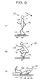
- the pressure sensor in the contact detector 40 mounted at the wrist 29L, 29R of one of the arms 13L and 13R responds to this and provides a contact signal for the control stage 51 which in turn judges that the robot is falling forward and provides the motor control unit 52 with control signals such as to cause the robot 10 to take a corrective falling action to have a safety fall with both the elbows 28L and 28R and both the knees 21L and 21R on the floor or ground as shown in Fig. 8C. Further, any shock acting on each of the elbows 28L and 28R and the knees 21L and 21R when it hits on the floor or ground is absorbed by the impact absorbing element 43 in the contact detector 40 mounted in each of these robot's parts.
- the control stage 51 can accurately determine an exact posture of the fall the robot 10 has. Hence, it can provide the motor control unit 52 with control signals such as to cause the robot 10 to take a rising action to get up on its feet. Then, provided with its cladding surfaces of the parts individually convex in contour, the robot 10 is allowed to make the successive rising movements smoothly.
- the biped walking humanoid robot 10 becoming unstable in its walking posture might also be falling backward.
- the pressure sensor in the contact detector 40 mounted at the center region of the sole of each of the feet 17L and 17R provides a pressure signal for the control stage 51 which in turn judges that the robot is walking stably to allow it to continue to walk.
- the pressure sensor 42 in the contact detector 40 mounted at the heel 31L, 31R of one of the feet 17L and 17R responds to this and provides a contact signal for the control stage 51 which in turn judges that the robot is falling backward and provides the motor control unit 52 with control signals such as to cause the robot 10 to take a corrective action to have a safety fall with the behind 32, the back 33 and both elbows 28L and 28R on the floor or ground as shown in Fig. 8C. Further, any shock acting on each of the behind 32, the back 33 and both elbows 28L and 28R when it hits on the floor or ground is absorbed by the impact absorbing element 43 in the contact detector 40 mounted in each of these robot's parts.
- the control stage 51 can accurately determine an exact posture of the fall the robot 10 has. Hence, it can provide the motor control unit 52 with control signals such as to cause the robot 10 to take a rising action to get up on its feet. Then, provided with its cladding surfaces of the parts individually convex in contour, the robot 10 is allowed to make the successive rising movements smoothly.
- a biped walking humanoid robot 10 of the present invention is allowed to take a corrective falling action to have a safety fall and then to smoothly shift to taking a rising action to get up on the feet, the corrective falling and rising actions meeting with the falling posture detected. Further, given the ability to grasp the posture of its fall, a biped walking humanoid robot 10 of the invention as illustrated is even capable of performing a forward and a backward roll in the course that it is falling to rise on its feet.
- a biped walking humanoid robot in which a contact detector having an impact absorbing material is disposed at each of those parts of the robot which can hit on the floor or ground when the robot is falling down to or rolling over it, namely, at each of an outer area of an elbow portion formed between the upper and lower arm portions, and an outer area of a wrist portion formed between the lower arm portion and the hand portion of each of the arm portions, and a lower side of a toe formed in the foot portion, a lower side of a heel portion formed in the foot portion, and an outer area of a knee portion formed between the upper and lower leg portions of each of the leg portions, and a hip region and a back region of the body portion whereby any shock acting on any of these parts hitting on the floor or ground can be absorbed by the impact absorbing material.
- the shock against the internal structure of each of these parts so alleviated, they are protected from any possible damage that should otherwise be the case when the biped walking humanoid robot happens to fall to or is attempting
- the state or type of this fall can be determined by a control means in response to a contact signal detected by the pressure sensor in the contact detector at a relevant part of the abovementioned robot parts which is brought into contact with the floor or ground. Then, on the basis of the type of the fall determined, the control means is allowed to act on the drive means to move the arm and leg parts suitably so as to cause the robot to take a corrective falling action to have a safety fall and then to move to taking a rising action to get up on its feet.
Landscapes
- Engineering & Computer Science (AREA)
- Mechanical Engineering (AREA)
- Robotics (AREA)
- Chemical & Material Sciences (AREA)
- Combustion & Propulsion (AREA)
- Transportation (AREA)
- Human Computer Interaction (AREA)
- Manipulator (AREA)
- Vibration Dampers (AREA)
Abstract
Description
Claims (9)
- A biped walking humanoid robot, comprising:wherein each of the leg portions includes two upper leg portions attached to the lower part of the body portion so as to be pivotally movable relative thereto triaxially, a lower leg portion attached to the upper leg portion so as to be pivotally movable relative thereto monoaxially, and a foot portion attached to the lower leg portion so as to be pivotally movable relative thereto biaxially,a body portion having an upper and a lower part, a pair of leg portions attached to the lower part of the body portion at a pair of its opposite sides, respectively, a pair of arm portions attached to the upper part of the body portion at a pair of its opposite sides, respectively, and a head portion attached to an upper end of the upper part of the body portion,
wherein each of the arm portions includes tow upper arms portion attached to the upper part of the body portion so as to be pivotally movable relative thereto biaxially, a lower arm portion attached to the upper arm portion so as to be pivotally movable relative thereto monoaxially, and a hand portion attached to the lower arm portion so as to be pivotally movable relative thereto biaxially,
wherein the body portion has an intermediate, anteflex region at which it is made able to bend forward; and
wherein the robot further comprises a drive means for pivotally moving each of the foot portion, the lower leg portion and the upper leg portion of each of the leg portions, and the hand portion, the lower arm portion and the upper arm portion of each of the arm portions, and the body portion at the anteflex region, and a control means for controlling driving actions of the drive means;the robot being characterized in that :there is provided a contact detector at each of an outer area of an elbow portion formed between the upper and lower arm portions, and an outer area of a wrist portion formed between the lower arm portion and the hand portion of each of said arm portions, and a lower side of a toe portion formed in the foot portion, a lower side of a heel portion formed in the foot portion, and an outer area of a knee portion formed between the upper and lower leg portions of each of said leg portions, and a hip region and a back region of said body portion, andsaid contact detector comprises a casing portion forming an outer covering surface of the robot at said contact detector, a pressure sensor for sensing a pressure acting on said casing portion and an impact absorbing material for relieving a shock acting on said casing portion. - A biped walking humanoid robot as set forth in claim 1, characterized in that in each of such contact detectors said pressure sensor and said impact absorbing material are integrally formed.
- A biped walking humanoid robot as set forth in claim 1, characterized in that in each of such contact detectors said casing portion, said pressure sensor and said impact absorbing material are formed integrally.
- A biped walking humanoid robot as set forth in claim 1, characterized in that in each of such contact detectors said casing portion lies at an outermost side thereof.
- A biped walking humanoid robot as set forth in claim 1, characterized in that in each of such contact detectors said pressure sensor lies at an outermost side thereof.
- A biped walking humanoid robot as set forth in claim 1, characterized in that in each of such contact detectors said impact absorbing material lies at an outermost side thereof.
- A biped walking humanoid robot as set forth in claim 1, characterized in that each of said body portion, the upper and lower arm portions of said arm portions, and the upper and lower leg portions of said leg portions has a curved outer covering surface that is convex in contour.
- A biped walking humanoid robot as set forth in claim 1, characterized in that:for each of said leg portionssaid foot portion is made pivotally movable relative to said lower leg portion in a pitch direction in a range of angles from -20 to +20 degrees or more,said lower leg portion is made pivotally movable relative to said upper leg portion in a pitch direction in an range of angles from 0 to +60 degrees or more, andsaid upper leg portion is made pivotally movable relative to said body portion in a pitch direction in a range of angles from 0 to +45 degrees or more, andsaid body portion is made able to bend forward in a range of angles from 0 to +30 degrees or more.
- A biped walking humanoid robot as set forth in claim I, characterized in that those of said drive means for pivotally moving the foot portion, the lower leg portion and the upper leg portion of each of said leg portions, respectively, are disposed inclined to one another so as not to hinder pivotal movements of said foot portion, said upper leg portion and said lower leg portion
Applications Claiming Priority (3)
| Application Number | Priority Date | Filing Date | Title |
|---|---|---|---|
| JP2001173263 | 2001-06-07 | ||
| JP2001173263A JP3682525B2 (en) | 2001-06-07 | 2001-06-07 | Biped walking humanoid robot |
| PCT/JP2002/005423 WO2002100607A1 (en) | 2001-06-07 | 2002-06-03 | Two-leg walking humanoid robot |
Publications (3)
| Publication Number | Publication Date |
|---|---|
| EP1393867A1 true EP1393867A1 (en) | 2004-03-03 |
| EP1393867A4 EP1393867A4 (en) | 2008-04-02 |
| EP1393867B1 EP1393867B1 (en) | 2009-02-25 |
Family
ID=19014754
Family Applications (1)
| Application Number | Title | Priority Date | Filing Date |
|---|---|---|---|
| EP02733274A Expired - Lifetime EP1393867B1 (en) | 2001-06-07 | 2002-06-03 | Two-leg walking humanoid robot |
Country Status (7)
| Country | Link |
|---|---|
| US (1) | US6902015B2 (en) |
| EP (1) | EP1393867B1 (en) |
| JP (1) | JP3682525B2 (en) |
| KR (1) | KR100515276B1 (en) |
| DE (1) | DE60231300D1 (en) |
| TW (1) | TW544380B (en) |
| WO (1) | WO2002100607A1 (en) |
Cited By (5)
| Publication number | Priority date | Publication date | Assignee | Title |
|---|---|---|---|---|
| US9555846B1 (en) | 2015-03-20 | 2017-01-31 | Google Inc. | Pelvis structure for humanoid robot |
| CN108890643A (en) * | 2018-06-25 | 2018-11-27 | 珠海格力智能装备有限公司 | Robot control method and device |
| CN109866218A (en) * | 2017-12-01 | 2019-06-11 | 优必选教育(深圳)有限公司 | Standing control method and device are fallen down by robot |
| CN110206840A (en) * | 2019-06-21 | 2019-09-06 | 重庆大学 | A kind of imitative femoral head shock-damping structure and walking robot |
| CN112025698A (en) * | 2020-07-13 | 2020-12-04 | 北京大学 | A robot fall protection method and system based on impact prediction and active compliance |
Families Citing this family (33)
| Publication number | Priority date | Publication date | Assignee | Title |
|---|---|---|---|---|
| JP3731118B2 (en) * | 2002-02-18 | 2006-01-05 | 独立行政法人科学技術振興機構 | Biped walking humanoid robot |
| JP3938326B2 (en) * | 2002-05-10 | 2007-06-27 | 川田工業株式会社 | Additional support structure for robots |
| US7761184B2 (en) * | 2003-03-23 | 2010-07-20 | Sony Corporation | Robot apparatus and control method thereof |
| US7603199B2 (en) | 2003-11-27 | 2009-10-13 | Honda Motor Co., Ltd. | Control device for mobile body |
| KR100657530B1 (en) * | 2005-03-31 | 2006-12-14 | 엘지전자 주식회사 | Lifting detection device of automatic driving robot |
| JP2006305642A (en) * | 2005-04-26 | 2006-11-09 | Kawada Kogyo Kk | Humanoid robot and removable buttock |
| KR100862190B1 (en) | 2006-11-30 | 2008-10-09 | 한국전자통신연구원 | Robot posture detection device and method |
| DK2190530T3 (en) * | 2007-09-13 | 2018-02-19 | Toby D Henderson | PATIENT POSITIONING SYSTEM |
| KR100863187B1 (en) * | 2008-01-10 | 2008-10-13 | (주)다사로봇 | Control System of Intelligent Robot Device and Its Control Method |
| US8352077B2 (en) * | 2008-12-19 | 2013-01-08 | Honda Motor Co., Ltd. | Inertia shaping for humanoid fall direction change |
| US8369991B2 (en) * | 2008-12-19 | 2013-02-05 | Honda Motor Co., Ltd. | Humanoid fall direction change among multiple objects |
| WO2012066678A1 (en) * | 2010-11-19 | 2012-05-24 | 株式会社日立製作所 | Self-directed movable body |
| US8880221B2 (en) | 2011-03-21 | 2014-11-04 | Honda Motor Co., Ltd. | Damage reduction control for humanoid robot fall |
| US9193403B2 (en) | 2013-03-20 | 2015-11-24 | Honda Motor Co., Ltd | Humanoid fall damage reduction |
| FR3021572B1 (en) * | 2014-06-03 | 2016-07-01 | Aldebaran Robotics | SAFETY OF A HUMANIDE ROBOT |
| US9499219B1 (en) * | 2014-08-25 | 2016-11-22 | Google Inc. | Touch-down sensing for robotic devices |
| JP6228097B2 (en) * | 2014-10-06 | 2017-11-08 | 本田技研工業株式会社 | Mobile robot |
| CN105346618B (en) * | 2015-11-20 | 2017-11-14 | 清华大学 | Band upper body biped robot's level walking method based on series elastic driver |
| CN105583856B (en) * | 2016-01-28 | 2019-01-01 | 苏州大学 | Tested humanoid robot |
| WO2017175532A1 (en) | 2016-04-05 | 2017-10-12 | 株式会社日立製作所 | Humanoid robot |
| JP6794800B2 (en) | 2016-11-29 | 2020-12-02 | セイコーエプソン株式会社 | robot |
| US10351189B2 (en) * | 2016-12-13 | 2019-07-16 | Boston Dynamics, Inc. | Whole body manipulation on a legged robot using dynamic balance |
| CN106737584A (en) * | 2016-12-29 | 2017-05-31 | 东莞市锝铼金机器人自动化有限公司 | A kind of anthropomorphic robot based on hollow driver, mini drive |
| CN107685788B (en) * | 2017-09-06 | 2023-10-27 | 滨州学院 | A football robot |
| CN110653814B (en) * | 2018-06-29 | 2021-09-17 | 深圳市优必选科技有限公司 | Robot control method, robot and device with storage function |
| CN110653811B (en) * | 2018-06-29 | 2021-10-29 | 深圳市优必选科技有限公司 | Control method, robot and computer storage medium |
| CN110450193B (en) * | 2019-09-06 | 2024-12-24 | 梁渤涛 | Walking support mechanism of biped walking robot |
| CN110695964A (en) * | 2019-09-27 | 2020-01-17 | 广州嘉欣电工科技有限公司 | Hub vehicle logo assembling method, system, device and storage medium |
| US12330722B2 (en) * | 2019-12-23 | 2025-06-17 | California Institute Of Technology | Synchronized multi-modal robot |
| CN113156926B (en) * | 2020-01-22 | 2024-05-17 | 深圳市优必选科技股份有限公司 | Method for establishing finite state machine of robot, finite state machine and robot |
| CN112894749B (en) * | 2021-01-15 | 2022-05-17 | 南通科橙机器人有限公司 | An artificial intelligence robot with protective structure |
| US12275154B2 (en) | 2021-11-12 | 2025-04-15 | Sanctuary Cognitive Systems Corporation | Robots and methods for protecting fragile components thereof |
| CN116141373A (en) * | 2023-02-08 | 2023-05-23 | 杭州云深处科技有限公司 | Replacement structure and replacement method for manipulator in quadruped robot to replace action foot |
Family Cites Families (13)
| Publication number | Priority date | Publication date | Assignee | Title |
|---|---|---|---|---|
| JPS6034295A (en) * | 1983-08-03 | 1985-02-21 | 株式会社日立製作所 | skin sensation sensor |
| JPS6133894A (en) * | 1984-07-25 | 1986-02-17 | 神鋼電機株式会社 | Safety arm and safety hand for industrial robot |
| JP2520019B2 (en) * | 1989-06-29 | 1996-07-31 | 本田技研工業株式会社 | Drive controller for legged mobile robot |
| US5255753A (en) * | 1989-12-14 | 1993-10-26 | Honda Giken Kogyo Kabushiki Kaisha | Foot structure for legged walking robot |
| JP3278467B2 (en) * | 1992-08-18 | 2002-04-30 | 本田技研工業株式会社 | Control device for mobile robot |
| JPH08393B2 (en) * | 1993-03-26 | 1996-01-10 | 日本電気株式会社 | Robot arm with collision prevention function |
| JP3655056B2 (en) * | 1997-08-04 | 2005-06-02 | 本田技研工業株式会社 | Control device for legged mobile robot |
| JP3528171B2 (en) * | 1999-11-12 | 2004-05-17 | ソニー株式会社 | Mobile robot apparatus and overturn control method for mobile robot apparatus |
| JP3555107B2 (en) * | 1999-11-24 | 2004-08-18 | ソニー株式会社 | Legged mobile robot and operation control method for legged mobile robot |
| JP2001239479A (en) * | 1999-12-24 | 2001-09-04 | Sony Corp | Legged mobile robot and armored module for robot |
| JP3511088B2 (en) * | 2000-04-10 | 2004-03-29 | 独立行政法人航空宇宙技術研究所 | Pressure distribution sensor for multi-joint care robot control |
| US6732015B2 (en) * | 2002-03-14 | 2004-05-04 | Kabushiki Kaisha Toshiba | Robot system |
| US6999851B2 (en) * | 2002-08-30 | 2006-02-14 | Sony Corporation | Robot apparatus and motion controlling method therefor |
-
2001
- 2001-06-07 JP JP2001173263A patent/JP3682525B2/en not_active Expired - Fee Related
-
2002
- 2002-06-03 EP EP02733274A patent/EP1393867B1/en not_active Expired - Lifetime
- 2002-06-03 WO PCT/JP2002/005423 patent/WO2002100607A1/en not_active Ceased
- 2002-06-03 DE DE60231300T patent/DE60231300D1/en not_active Expired - Lifetime
- 2002-06-03 US US10/466,316 patent/US6902015B2/en not_active Expired - Fee Related
- 2002-06-03 KR KR10-2003-7000965A patent/KR100515276B1/en not_active Expired - Fee Related
- 2002-06-04 TW TW091111931A patent/TW544380B/en active
Cited By (7)
| Publication number | Priority date | Publication date | Assignee | Title |
|---|---|---|---|---|
| US9555846B1 (en) | 2015-03-20 | 2017-01-31 | Google Inc. | Pelvis structure for humanoid robot |
| CN109866218A (en) * | 2017-12-01 | 2019-06-11 | 优必选教育(深圳)有限公司 | Standing control method and device are fallen down by robot |
| CN108890643A (en) * | 2018-06-25 | 2018-11-27 | 珠海格力智能装备有限公司 | Robot control method and device |
| CN110206840A (en) * | 2019-06-21 | 2019-09-06 | 重庆大学 | A kind of imitative femoral head shock-damping structure and walking robot |
| CN110206840B (en) * | 2019-06-21 | 2020-07-14 | 重庆大学 | A femoral head shock absorption structure and walking robot |
| CN112025698A (en) * | 2020-07-13 | 2020-12-04 | 北京大学 | A robot fall protection method and system based on impact prediction and active compliance |
| CN112025698B (en) * | 2020-07-13 | 2021-11-23 | 北京大学 | Robot falling protection method and system based on impact prediction and active compliance |
Also Published As
| Publication number | Publication date |
|---|---|
| WO2002100607A1 (en) | 2002-12-19 |
| US20040060746A1 (en) | 2004-04-01 |
| KR20030029789A (en) | 2003-04-16 |
| TW544380B (en) | 2003-08-01 |
| JP2002361575A (en) | 2002-12-18 |
| KR100515276B1 (en) | 2005-09-15 |
| EP1393867B1 (en) | 2009-02-25 |
| US6902015B2 (en) | 2005-06-07 |
| EP1393867A4 (en) | 2008-04-02 |
| JP3682525B2 (en) | 2005-08-10 |
| DE60231300D1 (en) | 2009-04-09 |
Similar Documents
| Publication | Publication Date | Title |
|---|---|---|
| EP1393867B1 (en) | Two-leg walking humanoid robot | |
| EP1440774B1 (en) | Bipedal humanoid | |
| JP3662996B2 (en) | Walking control device for legged mobile robot | |
| EP1535705B1 (en) | Legged mobile robot | |
| EP0488691B1 (en) | System for controlling locomotion of legged walking robot | |
| JP2011251396A (en) | Leg type mobile robot | |
| KR20040068438A (en) | Walking type robot and a moving method thereof | |
| JP3598507B2 (en) | Walking-type moving device, its walking control device, and walking control method | |
| JP3729459B2 (en) | Biped robot | |
| JP3148810B2 (en) | Control device for legged mobile robot | |
| JP3673869B2 (en) | Biped walking humanoid robot and its hand storage mechanism | |
| JP3627057B2 (en) | Biped humanoid robot | |
| JPH05253866A (en) | Walking control device for legged mobile robot | |
| JP2911984B2 (en) | Walking control device for legged mobile robot | |
| JP3024023B2 (en) | Walking control device for legged mobile robot | |
| JP3569767B2 (en) | Walking robot | |
| JP2997038B2 (en) | Walking control device for legged mobile robot | |
| JP2997037B2 (en) | Walking control device for legged mobile robot | |
| JP2004188530A (en) | Walking-type moving device, and its operation control device and operation control method | |
| JP2009125838A (en) | Biped walking robot and walking control method |
Legal Events
| Date | Code | Title | Description |
|---|---|---|---|
| PUAI | Public reference made under article 153(3) epc to a published international application that has entered the european phase |
Free format text: ORIGINAL CODE: 0009012 |
|
| 17P | Request for examination filed |
Effective date: 20030929 |
|
| AK | Designated contracting states |
Kind code of ref document: A1 Designated state(s): AT BE CH CY DE DK ES FI FR GB GR IE IT LI LU MC NL PT SE TR |
|
| RAP1 | Party data changed (applicant data changed or rights of an application transferred) |
Owner name: JAPAN SCIENCE AND TECHNOLOGY AGENCY |
|
| A4 | Supplementary search report drawn up and despatched |
Effective date: 20080303 |
|
| GRAP | Despatch of communication of intention to grant a patent |
Free format text: ORIGINAL CODE: EPIDOSNIGR1 |
|
| RBV | Designated contracting states (corrected) |
Designated state(s): DE FR GB NL |
|
| GRAS | Grant fee paid |
Free format text: ORIGINAL CODE: EPIDOSNIGR3 |
|
| GRAA | (expected) grant |
Free format text: ORIGINAL CODE: 0009210 |
|
| AK | Designated contracting states |
Kind code of ref document: B1 Designated state(s): DE FR GB NL |
|
| REG | Reference to a national code |
Ref country code: GB Ref legal event code: FG4D |
|
| REF | Corresponds to: |
Ref document number: 60231300 Country of ref document: DE Date of ref document: 20090409 Kind code of ref document: P |
|
| PLBE | No opposition filed within time limit |
Free format text: ORIGINAL CODE: 0009261 |
|
| STAA | Information on the status of an ep patent application or granted ep patent |
Free format text: STATUS: NO OPPOSITION FILED WITHIN TIME LIMIT |
|
| 26N | No opposition filed |
Effective date: 20091126 |
|
| PGFP | Annual fee paid to national office [announced via postgrant information from national office to epo] |
Ref country code: FR Payment date: 20100706 Year of fee payment: 9 |
|
| PGFP | Annual fee paid to national office [announced via postgrant information from national office to epo] |
Ref country code: NL Payment date: 20100614 Year of fee payment: 9 |
|
| PGFP | Annual fee paid to national office [announced via postgrant information from national office to epo] |
Ref country code: DE Payment date: 20100819 Year of fee payment: 9 Ref country code: GB Payment date: 20100618 Year of fee payment: 9 |
|
| REG | Reference to a national code |
Ref country code: NL Ref legal event code: V1 Effective date: 20120101 |
|
| GBPC | Gb: european patent ceased through non-payment of renewal fee |
Effective date: 20110603 |
|
| REG | Reference to a national code |
Ref country code: FR Ref legal event code: ST Effective date: 20120229 |
|
| REG | Reference to a national code |
Ref country code: DE Ref legal event code: R119 Ref document number: 60231300 Country of ref document: DE Effective date: 20120103 |
|
| PG25 | Lapsed in a contracting state [announced via postgrant information from national office to epo] |
Ref country code: FR Free format text: LAPSE BECAUSE OF NON-PAYMENT OF DUE FEES Effective date: 20110630 Ref country code: DE Free format text: LAPSE BECAUSE OF NON-PAYMENT OF DUE FEES Effective date: 20120103 |
|
| PG25 | Lapsed in a contracting state [announced via postgrant information from national office to epo] |
Ref country code: NL Free format text: LAPSE BECAUSE OF NON-PAYMENT OF DUE FEES Effective date: 20120101 |
|
| PG25 | Lapsed in a contracting state [announced via postgrant information from national office to epo] |
Ref country code: GB Free format text: LAPSE BECAUSE OF NON-PAYMENT OF DUE FEES Effective date: 20110603 |