EP1393616B1 - Improvements in or relating to shredders - Google Patents
Improvements in or relating to shredders Download PDFInfo
- Publication number
- EP1393616B1 EP1393616B1 EP20030255434 EP03255434A EP1393616B1 EP 1393616 B1 EP1393616 B1 EP 1393616B1 EP 20030255434 EP20030255434 EP 20030255434 EP 03255434 A EP03255434 A EP 03255434A EP 1393616 B1 EP1393616 B1 EP 1393616B1
- Authority
- EP
- European Patent Office
- Prior art keywords
- feed inlet
- walls
- fingers
- shredder
- finger
- Prior art date
- Legal status (The legal status is an assumption and is not a legal conclusion. Google has not performed a legal analysis and makes no representation as to the accuracy of the status listed.)
- Expired - Lifetime
Links
- 239000000463 material Substances 0.000 claims description 20
- 238000003780 insertion Methods 0.000 description 2
- 230000037431 insertion Effects 0.000 description 2
- 238000009264 composting Methods 0.000 description 1
- 239000010921 garden waste Substances 0.000 description 1
- 238000012986 modification Methods 0.000 description 1
- 230000004048 modification Effects 0.000 description 1
- 238000000926 separation method Methods 0.000 description 1
Images



Classifications
-
- A—HUMAN NECESSITIES
- A01—AGRICULTURE; FORESTRY; ANIMAL HUSBANDRY; HUNTING; TRAPPING; FISHING
- A01G—HORTICULTURE; CULTIVATION OF VEGETABLES, FLOWERS, RICE, FRUIT, VINES, HOPS OR SEAWEED; FORESTRY; WATERING
- A01G3/00—Cutting implements specially adapted for horticultural purposes; Delimbing standing trees
- A01G3/002—Cutting implements specially adapted for horticultural purposes; Delimbing standing trees for comminuting plant waste
-
- B—PERFORMING OPERATIONS; TRANSPORTING
- B02—CRUSHING, PULVERISING, OR DISINTEGRATING; PREPARATORY TREATMENT OF GRAIN FOR MILLING
- B02C—CRUSHING, PULVERISING, OR DISINTEGRATING IN GENERAL; MILLING GRAIN
- B02C18/00—Disintegrating by knives or other cutting or tearing members which chop material into fragments
- B02C18/06—Disintegrating by knives or other cutting or tearing members which chop material into fragments with rotating knives
- B02C18/08—Disintegrating by knives or other cutting or tearing members which chop material into fragments with rotating knives within vertical containers
- B02C18/12—Disintegrating by knives or other cutting or tearing members which chop material into fragments with rotating knives within vertical containers with drive arranged below container
-
- B—PERFORMING OPERATIONS; TRANSPORTING
- B02—CRUSHING, PULVERISING, OR DISINTEGRATING; PREPARATORY TREATMENT OF GRAIN FOR MILLING
- B02C—CRUSHING, PULVERISING, OR DISINTEGRATING IN GENERAL; MILLING GRAIN
- B02C18/00—Disintegrating by knives or other cutting or tearing members which chop material into fragments
- B02C18/06—Disintegrating by knives or other cutting or tearing members which chop material into fragments with rotating knives
- B02C18/16—Details
- B02C18/22—Feed or discharge means
- B02C18/2225—Feed means
- B02C18/2291—Feed chute arrangements
-
- B—PERFORMING OPERATIONS; TRANSPORTING
- B02—CRUSHING, PULVERISING, OR DISINTEGRATING; PREPARATORY TREATMENT OF GRAIN FOR MILLING
- B02C—CRUSHING, PULVERISING, OR DISINTEGRATING IN GENERAL; MILLING GRAIN
- B02C2201/00—Codes relating to disintegrating devices adapted for specific materials
- B02C2201/06—Codes relating to disintegrating devices adapted for specific materials for garbage, waste or sewage
- B02C2201/066—Codes relating to disintegrating devices adapted for specific materials for garbage, waste or sewage for garden waste
Definitions
- the present invention relates to improvements in or relating to shredders.
- it relates to an inlet for a shredding or chopping machine of the type used for shredding plant material such as garden waste.
- plant material such as twigs, branches and so on is typically chopped or shredded into smaller pieces suitable for composting or mulching by means of rapidly rotating shredding blades or contra-rotating shredding elements or cogs.
- the cutting elements are conventionally mounted at a lower end of an elongate housing having an inlet having a feed opening for receipt of the material to be shredded and an outlet downstream of the cutting elements through which shredded material is ejected.
- the elongate nature of the housing is advantageous from a safety viewpoint, it can allow material entering the housing through the inlet becoming entangled or poorly aligned with respect to the cutters such that the apparatus can be clogged with plant material and cease to work.
- US 5,323,927 which is considered to represent the closest prior art, shows a vegetation shredder having a cloverleaf design inlet in which inverted conical walls incline towards a central aperture to guide vegetation towards the aperture and into the shredding chamber.
- the present invention seeks to address these problems in the prior art.
- the present invention provides a feed inlet for a shredder apparatus, the feed inlet having an opening between opposed first and second walls, wherein at least one of the first and second walls includes at least one finger projecting into the opening.
- each finger includes an inclined upper surface.
- each of the first and second walls is inclined. More preferably, the second wall is inclined at a greater angle to the angle of inclination of the first wall.
- each of the first and second walls includes at least one inclined finger projecting into the opening.
- each of the first and second walls includes a plurality of inclined fingers. More preferably, each of the first and second walls includes two or three inclined fingers.
- the fingers of the first and second walls are arranged in opposed pairs.
- the fingers are uniformly spaced.
- each of the fingers is narrower at its upper end than at its lower end such that the spaces between adjacent fingers taper to aid feeding of material through the inlet.
- the upper surface of each finger is substantially flat. In an alternative embodiment, the upper surface of each finger is generally arcuate, preferably convex.
- the present invention also provides a shredder incorporating a feed inlet as defined above.
- a feed inlet in accordance with the present invention for a shredder is shown generally at 10.
- the inlet 10 has an inlet body 11 of generally rectangular configuration having opposed first and second main walls 12,13 spaced apart by opposed side walls 14,15. The walls define an aperture 20 therebetween.
- each of the first and second main walls and the side walls 14,15 are inclined to aid direction, in use, of plant material into the shredder body upon which the inlet body will be mounted.
- the inclination of second main wall 13 is greater than that of first main wall 12. This asymmetrical inclination allows the user to guide difficult material to be fed into the shredder along the shallower slope of first main wall 12 whereupon it contacts the steeper slope of second main wall 13 guiding the material downwardly towards the shredding elements.
- Each of the first and second main walls includes a respective array of fingers 21,22 projecting therefrom into aperture 20 forming opposed spaced finger pairs, 21a-22a, 21b-22b etc.
- the fingers 21,22 divide the aperture 20 into a central elongate aperture 20a (shown by the dotted line in Figure 2 ) with a plurality of lateral or branching apertures 20b.
- each finger 21,22 is inclined, typically with first wall fingers 21 at a shallower angle of inclination to that of second wall fingers 22 and at a shallower angle of inclination to that of its respective wall 12,13.
- each finger is typically generally wedge-shaped, tapering widthways upwardly and being broader at its lower end 23 than at its upper end 24.
- the profile of any or all of the fingers need not be wedge-shaped.
- the surfaces may be concave.
- the fingers in each array of fingers 21,22 are of equal lengths, extending into aperture 20. This is not an essential requirement and a non-symmetrical arrangement may be provided within, of course, the constraints of any safety standard requirements. Equally, each of the fingers in each array need not, as is the case in the embodiment shown, be of equal width, nor is it an essential feature that the fingers 21,22 project perpendicularly from respective walls 12,13.
- aperture 20 need not be straight (parallel to side walls 12, 13). In alternative embodiments, aperture 20 is wholly or partially arcuate.
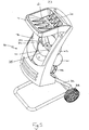
- FIG. 5 illustrates the inlet as a component of a complete shredder 30.
- Shredder 30 has a shredder housing 31 mounted for movement upon a frame 32 carrying a pair of wheels 33.
- Housing 31 includes an inlet 10 of the type described above in communication with a feed chute 34 which directs inserted plant material towards a cutter disc 35 mounting two cutters 40 rotationally separated by 180°.
- Cutter disc 35 is driven by an electric motor mounted in a motor housing 41 part of shredder housing 31, through an indirect drive assembly housed within a drive housing 42 part of shredder housing 31.
- Shredded plant material is ejected through an outlet of the shredder housing (obscured).
- the present invention whilst complying with safety standards as regards maximum dimensions of the various sections of aperture 20, in total provides a greater aperture area than would otherwise be possible, allowing insertion of bulkier plant material than is allowed by a conventional shredder feed inlet and insertion of more oddly-shaped materials.
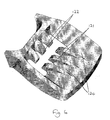
- Figures 6 and 7 illustrate a modification to the first embodiment described above.
- the upper surface of each finger 21,22 is substantially flat
- the upper surface of each finger 121,122 is generally curved, preferably convex.
- the upper surface of the spaces 124 adjacent fingers 121 are also convexly curved. Curvature of these surfaces aids direction of material to be shredded into the feed chute 34.
Landscapes
- Engineering & Computer Science (AREA)
- Food Science & Technology (AREA)
- Life Sciences & Earth Sciences (AREA)
- Biodiversity & Conservation Biology (AREA)
- Ecology (AREA)
- Forests & Forestry (AREA)
- Environmental Sciences (AREA)
- Crushing And Pulverization Processes (AREA)
Description
- The present invention relates to improvements in or relating to shredders. In particular, it relates to an inlet for a shredding or chopping machine of the type used for shredding plant material such as garden waste.
- In such shredding or chopping machines, plant material such as twigs, branches and so on is typically chopped or shredded into smaller pieces suitable for composting or mulching by means of rapidly rotating shredding blades or contra-rotating shredding elements or cogs. Obviously, it is necessary to ensure that the user of such machines cannot contact the rotating elements when in use. Accordingly, the cutting elements are conventionally mounted at a lower end of an elongate housing having an inlet having a feed opening for receipt of the material to be shredded and an outlet downstream of the cutting elements through which shredded material is ejected.
- Although the elongate nature of the housing is advantageous from a safety viewpoint, it can allow material entering the housing through the inlet becoming entangled or poorly aligned with respect to the cutters such that the apparatus can be clogged with plant material and cease to work.
- Furthermore, the safety standards with which the inlets of such shredders must comply specify maximum separations between walls of the feed opening and maximum diameters for any circular feed openings. This places a considerable restriction on the size of material which can be inserted into the apparatus.
-
US 5,323,927 , which is considered to represent the closest prior art, shows a vegetation shredder having a cloverleaf design inlet in which inverted conical walls incline towards a central aperture to guide vegetation towards the aperture and into the shredding chamber. - The present invention seeks to address these problems in the prior art.
- In its broadest sense, the present invention provides a feed inlet for a shredder apparatus, the feed inlet having an opening between opposed first and second walls, wherein at least one of the first and second walls includes at least one finger projecting into the opening.
- Typically, each finger includes an inclined upper surface.
- Preferably, each of the first and second walls is inclined. More preferably, the second wall is inclined at a greater angle to the angle of inclination of the first wall.
- Preferably, each of the first and second walls includes at least one inclined finger projecting into the opening.
- Preferably, each of the first and second walls includes a plurality of inclined fingers. More preferably, each of the first and second walls includes two or three inclined fingers.
- Preferably, the fingers of the first and second walls are arranged in opposed pairs.
- Preferably, the fingers are uniformly spaced.
- Preferably, each of the fingers is narrower at its upper end than at its lower end such that the spaces between adjacent fingers taper to aid feeding of material through the inlet.
- In one embodiment, the upper surface of each finger is substantially flat. In an alternative embodiment, the upper surface of each finger is generally arcuate, preferably convex.
- In a further aspect, the present invention also provides a shredder incorporating a feed inlet as defined above.
- The above and other aspects of the present invention will now be described in further detail, by way of example only, with reference to the accompanying drawings, in which:
-
Figure 1 is a perspective view of a first embodiment of a shredder feed inlet in accordance with the present invention; -
Figure 2 is a plan view of the embodiment ofFigure 1 ; -
Figure 3 is a sectional view along line III-III ofFigure 2 ; -
Figure 4 is a sectional view along line IV-IV ofFigure 2 ; -
Figure 5 is a part cut-away perspective view of an embodiment of a shredder in accordance with the second aspect of the present invention; -
Figure 6 is a first perspective view of a second embodiment of a shredder feed inlet in accordance with the present invention; and -
Figure 7 is a second perspective view of the embodiment ofFigure 6 . - Referring to the drawings, a feed inlet in accordance with the present invention for a shredder is shown generally at 10. The
inlet 10 has an inlet body 11 of generally rectangular configuration having opposed first and secondmain walls opposed side walls aperture 20 therebetween. - In the embodiment shown, each of the first and second main walls and the
side walls main wall 13 is greater than that of firstmain wall 12. This asymmetrical inclination allows the user to guide difficult material to be fed into the shredder along the shallower slope of firstmain wall 12 whereupon it contacts the steeper slope of secondmain wall 13 guiding the material downwardly towards the shredding elements. - Each of the first and second main walls includes a respective array of
fingers aperture 20 forming opposed spaced finger pairs, 21a-22a, 21b-22b etc. Thefingers aperture 20 into a centralelongate aperture 20a (shown by the dotted line inFigure 2 ) with a plurality of lateral orbranching apertures 20b. - As is most clearly seen from
Figure 3 , eachfinger first wall fingers 21 at a shallower angle of inclination to that ofsecond wall fingers 22 and at a shallower angle of inclination to that of itsrespective wall - As can be seen from
Figure 4 , typically, each finger is typically generally wedge-shaped, tapering widthways upwardly and being broader at itslower end 23 than at itsupper end 24. This introduces the reverse characteristic inlateral apertures 20b whereby they taper downwardly to assist the user of a shredder incorporating the inventive inlet in directing plant material downwardly towards the shredding elements. However, the profile of any or all of the fingers need not be wedge-shaped. For example, the surfaces may be concave. - In the embodiment illustrated, the fingers in each array of
fingers aperture 20. This is not an essential requirement and a non-symmetrical arrangement may be provided within, of course, the constraints of any safety standard requirements. Equally, each of the fingers in each array need not, as is the case in the embodiment shown, be of equal width, nor is it an essential feature that thefingers respective walls -
Aperture 20 need not be straight (parallel toside walls 12, 13). In alternative embodiments,aperture 20 is wholly or partially arcuate. -
Figure 5 illustrates the inlet as a component of acomplete shredder 30. Shredder 30 has a shredder housing 31 mounted for movement upon aframe 32 carrying a pair ofwheels 33. Housing 31 includes aninlet 10 of the type described above in communication with afeed chute 34 which directs inserted plant material towards acutter disc 35 mounting twocutters 40 rotationally separated by 180°.Cutter disc 35 is driven by an electric motor mounted in a motor housing 41 part of shredder housing 31, through an indirect drive assembly housed within adrive housing 42 part of shredder housing 31. Shredded plant material is ejected through an outlet of the shredder housing (obscured). - The present invention, whilst complying with safety standards as regards maximum dimensions of the various sections of
aperture 20, in total provides a greater aperture area than would otherwise be possible, allowing insertion of bulkier plant material than is allowed by a conventional shredder feed inlet and insertion of more oddly-shaped materials. -
Figures 6 and7 illustrate a modification to the first embodiment described above. Whereas, in the first embodiment, the upper surface of eachfinger spaces 124adjacent fingers 121 are also convexly curved. Curvature of these surfaces aids direction of material to be shredded into thefeed chute 34.
Claims (11)
- A feed inlet (10) for a shredder apparatus (30) the feed inlet (10) having an opening (20) between opposed first and second walls (12, 13), wherein at least one of the first and second walls (12, 13) includes at least one finger (21, 22) projecting into the opening (20).
- A feed inlet (10) as claimed in Claim 1 wherein each finger (21, 22) includes an inclined upper surface.
- A feed inlet (10) as claimed in Claim 1 or Claim 2 wherein each of the first and second walls (12,13) is inclined.
- A feed inlet (10) as claimed in Claim 3 wherein the second wall (13) is inclined at a greater angle to the angle of inclination of the first wall (12).
- A feed inlet (10) as claimed in any one of claims 1 to 4 wherein each of the first and second walls (12,13) includes at least one inclined finger (21,22) projecting into the opening (20).
- A feed inlet (10) as claimed in Claim 5 wherein each of the first and second walls (12,13) includes a plurality of inclined fingers (21, 22)
- A feed inlet (10) as claimed in Claim 6 wherein each of the first and second walls (12, 13) includes two or three inclined fingers (21, 22).
- A feed inlet (10) as claimed in any one of claims 5 to 7 wherein the fingers (21, 22) of the first and second walls (12, 13) are arranged in opposed pairs.
- A feed inlet (10) as claimed in any preceding claim wherein each of the fingers (21, 22) is narrower at its upper end (24) than at its lower end (23).
- A feed inlet (10) as claimed in any preceding claim wherein the upper surface of each finger is generally arcuate, preferably convex.
- A plant material shredding apparatus (30) comprising a shredding element (35) mounted within a shredder housing (31), the housing (31) having an inlet (10) as defined in any one of claims 1 to 10 for receipt, in use of plant material to be shredded, and an outlet for egress of shredded material.
Applications Claiming Priority (4)
| Application Number | Priority Date | Filing Date | Title |
|---|---|---|---|
| GB0220647A GB0220647D0 (en) | 2002-08-30 | 2002-08-30 | Shredder inlet |
| GB0220647 | 2002-08-30 | ||
| GB0310196 | 2003-05-02 | ||
| GB0310196 | 2003-05-02 |
Publications (2)
| Publication Number | Publication Date |
|---|---|
| EP1393616A1 EP1393616A1 (en) | 2004-03-03 |
| EP1393616B1 true EP1393616B1 (en) | 2008-02-27 |
Family
ID=31497268
Family Applications (1)
| Application Number | Title | Priority Date | Filing Date |
|---|---|---|---|
| EP20030255434 Expired - Lifetime EP1393616B1 (en) | 2002-08-30 | 2003-08-29 | Improvements in or relating to shredders |
Country Status (2)
| Country | Link |
|---|---|
| EP (1) | EP1393616B1 (en) |
| DE (1) | DE60319313T2 (en) |
Cited By (1)
| Publication number | Priority date | Publication date | Assignee | Title |
|---|---|---|---|---|
| DE102012009786A1 (en) | 2012-05-16 | 2013-11-21 | Al-Ko Kober Ag | Feed device for comminution device, particularly harvester for cutting branches, has rolling unit with two different diameters in axial direction, where outlet cross-section of feed opening is limited by two rolling units |
Families Citing this family (2)
| Publication number | Priority date | Publication date | Assignee | Title |
|---|---|---|---|---|
| EP2072137B1 (en) | 2007-12-21 | 2019-05-15 | Robert Bosch Gmbh | Vegetation shredders |
| DE202012003150U1 (en) * | 2012-03-28 | 2012-04-20 | Atika Gmbh & Co. Kg | garden shredders |
Family Cites Families (2)
| Publication number | Priority date | Publication date | Assignee | Title |
|---|---|---|---|---|
| DE3621418A1 (en) * | 1986-06-26 | 1988-01-14 | Lescha Maschf Gmbh | DEVICE FOR CHOPPING GARDEN WASTE |
| US5323927A (en) * | 1993-08-18 | 1994-06-28 | Viking-Umwelttechnik Gmbh | Receptacle means |
-
2003
- 2003-08-29 EP EP20030255434 patent/EP1393616B1/en not_active Expired - Lifetime
- 2003-08-29 DE DE2003619313 patent/DE60319313T2/en not_active Expired - Lifetime
Cited By (1)
| Publication number | Priority date | Publication date | Assignee | Title |
|---|---|---|---|---|
| DE102012009786A1 (en) | 2012-05-16 | 2013-11-21 | Al-Ko Kober Ag | Feed device for comminution device, particularly harvester for cutting branches, has rolling unit with two different diameters in axial direction, where outlet cross-section of feed opening is limited by two rolling units |
Also Published As
| Publication number | Publication date |
|---|---|
| EP1393616A1 (en) | 2004-03-03 |
| DE60319313T2 (en) | 2009-03-26 |
| DE60319313D1 (en) | 2008-04-10 |
Similar Documents
| Publication | Publication Date | Title |
|---|---|---|
| AU624535B2 (en) | Document shredding machine | |
| EP1438887B1 (en) | Device for chopping the stalks after the ears of corn have been cut off in a combine harvester | |
| CA2072445A1 (en) | Document shredding machine with stripper and cutting mechanism therefor | |
| US20050242221A1 (en) | Two-shaft industrial shredder | |
| WO2007092110A1 (en) | Knife assembly and chipping knife therefor | |
| US7896275B2 (en) | Comminution plant | |
| WO2008085180A1 (en) | Double-sided wear insert for a chipper | |
| US4545539A (en) | Cutting mill for the comminution of synthetic material bodies such as runners, injection moulding parts, blown moulding parts and the like | |
| US6513740B2 (en) | Blade of a paper shredder | |
| WO2006002331A1 (en) | Pre-directing insert for a bi-directional exhausting handheld planer | |
| EP1393616A1 (en) | Improvements in or relating to shredders | |
| EP1658899A1 (en) | Blade pairs for a paper shredder | |
| US12076727B2 (en) | Apparatus for pulverizing material including a stationary housing | |
| US4830288A (en) | Forage harvester | |
| EP2072137B1 (en) | Vegetation shredders | |
| EP1413358B1 (en) | Shredder | |
| JP5158853B2 (en) | 厨 芥 Processing device | |
| US6053442A (en) | High-speed crushing apparatus | |
| EP1533039B1 (en) | Round undulating blade and blade module for shredder | |
| US4544105A (en) | Separating device for a wood chipper | |
| US7500629B2 (en) | Shredder blade and method of manufacturing same | |
| US20030066918A1 (en) | Forage harvester comprising an abrading base | |
| JPH08141424A (en) | Cutting machine | |
| EP2608709B1 (en) | Device with reduced static and slide friction | |
| CN101389249A (en) | Discharging accessory for a rotary work tool for cutting up food, and device for cutting up food |
Legal Events
| Date | Code | Title | Description |
|---|---|---|---|
| PUAI | Public reference made under article 153(3) epc to a published international application that has entered the european phase |
Free format text: ORIGINAL CODE: 0009012 |
|
| AK | Designated contracting states |
Kind code of ref document: A1 Designated state(s): AT BE BG CH CY CZ DE DK EE ES FI FR GB GR HU IE IT LI LU MC NL PT RO SE SI SK TR |
|
| AX | Request for extension of the european patent |
Extension state: AL LT LV MK |
|
| 17P | Request for examination filed |
Effective date: 20040901 |
|
| AKX | Designation fees paid |
Designated state(s): DE FR GB |
|
| 17Q | First examination report despatched |
Effective date: 20061019 |
|
| GRAP | Despatch of communication of intention to grant a patent |
Free format text: ORIGINAL CODE: EPIDOSNIGR1 |
|
| GRAS | Grant fee paid |
Free format text: ORIGINAL CODE: EPIDOSNIGR3 |
|
| GRAA | (expected) grant |
Free format text: ORIGINAL CODE: 0009210 |
|
| AK | Designated contracting states |
Kind code of ref document: B1 Designated state(s): DE FR GB |
|
| REG | Reference to a national code |
Ref country code: GB Ref legal event code: FG4D |
|
| REF | Corresponds to: |
Ref document number: 60319313 Country of ref document: DE Date of ref document: 20080410 Kind code of ref document: P |
|
| ET | Fr: translation filed | ||
| PLBE | No opposition filed within time limit |
Free format text: ORIGINAL CODE: 0009261 |
|
| STAA | Information on the status of an ep patent application or granted ep patent |
Free format text: STATUS: NO OPPOSITION FILED WITHIN TIME LIMIT |
|
| 26N | No opposition filed |
Effective date: 20081128 |
|
| REG | Reference to a national code |
Ref country code: FR Ref legal event code: PLFP Year of fee payment: 14 |
|
| REG | Reference to a national code |
Ref country code: FR Ref legal event code: PLFP Year of fee payment: 15 |
|
| REG | Reference to a national code |
Ref country code: FR Ref legal event code: PLFP Year of fee payment: 16 |
|
| PGFP | Annual fee paid to national office [announced via postgrant information from national office to epo] |
Ref country code: GB Payment date: 20220824 Year of fee payment: 20 |
|
| PGFP | Annual fee paid to national office [announced via postgrant information from national office to epo] |
Ref country code: FR Payment date: 20220822 Year of fee payment: 20 |
|
| PGFP | Annual fee paid to national office [announced via postgrant information from national office to epo] |
Ref country code: DE Payment date: 20221025 Year of fee payment: 20 |
|
| P01 | Opt-out of the competence of the unified patent court (upc) registered |
Effective date: 20230411 |
|
| REG | Reference to a national code |
Ref country code: DE Ref legal event code: R071 Ref document number: 60319313 Country of ref document: DE |
|
| REG | Reference to a national code |
Ref country code: GB Ref legal event code: PE20 Expiry date: 20230828 |
|
| PG25 | Lapsed in a contracting state [announced via postgrant information from national office to epo] |
Ref country code: GB Free format text: LAPSE BECAUSE OF EXPIRATION OF PROTECTION Effective date: 20230828 |