EP1393613A2 - Vorrichtung zur Steuerung einer Überladeeinrichtung - Google Patents
Vorrichtung zur Steuerung einer Überladeeinrichtung Download PDFInfo
- Publication number
- EP1393613A2 EP1393613A2 EP03015853A EP03015853A EP1393613A2 EP 1393613 A2 EP1393613 A2 EP 1393613A2 EP 03015853 A EP03015853 A EP 03015853A EP 03015853 A EP03015853 A EP 03015853A EP 1393613 A2 EP1393613 A2 EP 1393613A2
- Authority
- EP
- European Patent Office
- Prior art keywords
- transfer device
- pivoting
- horizontal axis
- range
- housing part
- Prior art date
- Legal status (The legal status is an assumption and is not a legal conclusion. Google has not performed a legal analysis and makes no representation as to the accuracy of the status listed.)
- Granted
Links
- 238000012546 transfer Methods 0.000 claims abstract description 94
- 238000000034 method Methods 0.000 claims abstract description 9
- 238000003306 harvesting Methods 0.000 claims description 19
- 239000004459 forage Substances 0.000 description 23
- 241001124569 Lycaenidae Species 0.000 description 8
- 230000006870 function Effects 0.000 description 6
- 238000012544 monitoring process Methods 0.000 description 4
- 244000025254 Cannabis sativa Species 0.000 description 3
- 238000013459 approach Methods 0.000 description 3
- 240000001327 Echinochloa stagnina Species 0.000 description 1
- 240000000111 Saccharum officinarum Species 0.000 description 1
- 235000007201 Saccharum officinarum Nutrition 0.000 description 1
- 230000006978 adaptation Effects 0.000 description 1
- 230000002411 adverse Effects 0.000 description 1
- 238000010420 art technique Methods 0.000 description 1
- 230000001419 dependent effect Effects 0.000 description 1
- 238000013461 design Methods 0.000 description 1
- 238000011161 development Methods 0.000 description 1
- 230000018109 developmental process Effects 0.000 description 1
- 238000010586 diagram Methods 0.000 description 1
- 238000012432 intermediate storage Methods 0.000 description 1
- 239000000463 material Substances 0.000 description 1
- 230000000630 rising effect Effects 0.000 description 1
- 239000000523 sample Substances 0.000 description 1
- 239000002689 soil Substances 0.000 description 1
- 238000003860 storage Methods 0.000 description 1
- 210000003813 thumb Anatomy 0.000 description 1
Images


Classifications
-
- A—HUMAN NECESSITIES
- A01—AGRICULTURE; FORESTRY; ANIMAL HUSBANDRY; HUNTING; TRAPPING; FISHING
- A01D—HARVESTING; MOWING
- A01D43/00—Mowers combined with apparatus performing additional operations while mowing
- A01D43/08—Mowers combined with apparatus performing additional operations while mowing with means for cutting up the mown crop, e.g. forage harvesters
- A01D43/086—Mowers combined with apparatus performing additional operations while mowing with means for cutting up the mown crop, e.g. forage harvesters and means for collecting, gathering or loading mown material
- A01D43/087—Mowers combined with apparatus performing additional operations while mowing with means for cutting up the mown crop, e.g. forage harvesters and means for collecting, gathering or loading mown material with controllable discharge spout
-
- A—HUMAN NECESSITIES
- A01—AGRICULTURE; FORESTRY; ANIMAL HUSBANDRY; HUNTING; TRAPPING; FISHING
- A01D—HARVESTING; MOWING
- A01D43/00—Mowers combined with apparatus performing additional operations while mowing
- A01D43/06—Mowers combined with apparatus performing additional operations while mowing with means for collecting, gathering or loading mown material
- A01D43/07—Mowers combined with apparatus performing additional operations while mowing with means for collecting, gathering or loading mown material in or into a trailer
Definitions
- the invention relates to a device for controlling a transfer device at a harvesting machine, wherein the transfer device to a vertical Axis and to change a height adjustment by a horizontal Axis pivotable at a distance adjacent to a housing part of the harvester is arranged with Schwenk Schl.sbegrenzungsmitteln, which the maximum permissible swivel range of the transfer device to the vertical axis in the direction of the relevant housing part to avoid limit a collision with the housing part.
- Schwenk Switzerlandsbegrenzungsmitteln the maximum permissible swivel range of the transfer device to the vertical axis in the direction of the relevant housing part to avoid limit a collision with the housing part.
- the concerns Invention a harvester with such a device and a corresponding Method for controlling a transfer device on a Harvester.
- Self-propelled harvesters such as forage harvesters, combine harvester, Sugarcane harvesters and the like usually have one Kochlade issued on, z. B. a chute, a grain tank emptying pipe, a conveyor chain or a conveyor belt, with which the crop is transferred from the harvester to a transport vehicle. If the harvested crop, such as a forage harvester, during one Harvesting should be continuously overloaded, the transport vehicle must during the harvest ride parallel next to or behind the harvester herfahren.
- the transfer device by the pivoting be positioned around the vertical axis and the horizontal axis so that the ejected or outgoing product flow at the desired Spot on the transport vehicle meets.
- the transfer device By pivoting about the horizontal axis while the height adjustment the transfer device to different levels of transport vehicles and adapted to the rising level in the transport vehicle.
- the overload device By the pivoting about the vertical axis is the overload device a transport position provided for road driving, in which the transfer device placed back on a transport bracket, brought to a suitable lateral position during harvesting with parallel drive.
- the Kochlade annoyed at a row Abemtung of a field piece are regularly swung to the right and left, because the transport vehicle always on the already harvested area of the Field piece must drive and therefore alternately right and left side located next to the harvester.
- the pivoting of the transfer device in addition to the vertical axis of rotation is for uniform filling used the transport vehicle. Is the transport vehicle at one Place sufficiently filled, the driver of the Emtemaschine the Kochlade responded so swivel that the product stream to another location within of the transport vehicle.
- the pivoting about the vertical axis is usually done by means of a Turntable over which the transfer device coupled with the harvester is.
- a Turntable over which the transfer device coupled with the harvester is.
- housing parts the harvester such as the cab, up over the Level in which the turntable is arranged protrude.
- the Transvoting movement of the transfer device about the vertical axis of rotation stop in good time before the relevant housing part.
- the driver operates the transfer device when traveling in parallel, preferably as close as possible to the cabin rear wall, d. H. at the front stop.
- the invention is therefore based on the object, a device or a Method for controlling a transfer device on a harvester to create the type mentioned, which is a more comfortable operation and monitoring the Matterlade raised by the driver allowed.
- the allowed Pivoting range depending on the current height setting of the Overloader changed.
- the pivoting range to exactly the shape of the free pivoting obstructing housing part and adapted the shape of the Studentslade coupled and thereby at least in certain Height settings of the overload device can be extended.
- the Driver can therefore at a suitably selected height position - within the given in this height adjustment swivel range limits - the transfer device continue to pivot forward, for example also over the roof of a driver's cabin.
- the transfer device also from several, each over horizontal Axes interconnected segments be constructed.
- This case can also be a separate extension to the pivoting range Height swiveling of individual segments around the corresponding horizontal Axis done.
- the driver gets through the thus given advanced settings relieved in the control and monitoring of the transfer device. Furthermore, the larger pivoting range makes a more flexible adaptation the transfer device to the parallel moving transport vehicle possible.
- the invention is particularly advantageous when used on forage harvesters, here on the one hand, despite the close distance between the chute and Driver's cab due to the curved shape of the discharge chute in certain Height settings considerable swivel range extensions are possible and on the other just in these vehicles, which unlike harvesters have no intermediate storage for the crop, inevitably always a permanent overload in a transport vehicle is required.
- the invention is also in all other harvesting machines with corresponding swiveling transfer devices and in the pivoting area protruding housing parts advantageous used.
- the swivel range limiting means designed and / or arranged such that the Transfer device during a pivoting in the direction of the housing part, about the at a certain height adjustment of the Matterlade observed maximum swivel range addition to at least automatically a horizontal axis - d. H. possibly also in segments - in vertical Direction is pivoted higher. Ie. the pivoting movement of Overloader will not reach the critical angle of current maximum swinging range is stopped, but instead it becomes a Swiveling over the swivel range in the starting position admitted, but at the same time the Matterlade issued pivoted so higher that in each height settings respectively applicable pivoting range limits are met and a collision is safely avoided with the housing part.
- the swivel range limiting means can be designed in this case and / or arranged that with increasing height adjustment of Studentslade attended the maximum permissible swivel range continuously is extended. Alternatively, with increasing height adjustment of Overloading device gradually the maximum permissible swivel range be extended. Accordingly, the automatic boost the transfer device at a pivoting against the swivel range Enclosing housing part both continuously and in style take place that the pivoting movement about the vertical axis intermittently interrupted is first, then the Kochlade worn automatically in one higher position is raised and then continue around the vertical axis is pivoted, etc.
- the Device for determining a height position value which the Height adjustment of the Matterlade worn represented. This can happen to act on sensors on the Matterlade Published, depending on the height setting generate a corresponding signal. Likewise it can This is also a memory device or a buffer act to the control commands or appropriate control signals to the actuator, that specify a specific position to register and cache.
- the device has a user interface for generating a control command for pivoting the Transfer device around the vertical axis.
- the device includes a control unit based on the altitude position value Limit values for the associated, maximum swivel range are determined and based on the control command and taking into account the determined Pivoting range limits a control signal to an adjusting device to the corresponding Swiveling the transfer device around the vertical axis outputs.
- the control unit forms an "electronic stop", when the Schwenk Switzerlandsgrenztude the pivoting movement stops, d. H. no control signal to the adjusting device for pivoting to output the vertical axis and instead, for example, the Driver signals the reaching of the swivel range limit.
- control unit also has means for, in this case, another control signal for moving the transfer device to a different height setting with a larger pivoting range to an adjusting device for pivoting the Matterlade issued to output the horizontal axis.
- the Studentslade dressed is pivoted so long up until a Height adjustment is achieved with a sufficient swivel range or the slewing range can no longer be extended by a politicianrwolf can.
- the control unit can also, as soon as the pivot angle with respect the vertical axis is fixed, which started according to the control command should be looking for a suitable height adjustment, in which the pivoting angle is within the Schwenk Switzerlandsgrenzhong. It is then approached directly to this optimal height adjustment.
- the control unit may be in the form of software on a computer unit, for example the device according to the invention for controlling the transfer device be realized.
- the swivel range limiting means for example, a Scenery, z. B. with a ramp, and a cooperating Scanning include. At least when the transfer device is in a certain height setting range, this drives Scanning device in the pivoting of the transfer device to the vertical axis in regions, d. H. at least in a certain section, along the scenery.
- the scanning device comprises a corresponding control element, For example, a hydraulic valve or a potentiometer, which with coupled to a probe element that moves along the backdrop.
- the pivot range limiting means comprises while defining differently wide swivel ranges several stepped mechanical stops and / or limit switches.
- the arrangement of these stops and / or limit switches is so chosen that the Kochlade worn at a pivoting about the vertical Axis in the direction of the relevant housing part in different Height adjustment in each case against various of the stops and / or limit switches moves.
- the transfer device on the tax side, d. H. on their way from the harvester pointing the way End an adjustable ejector flap on.
- ejectors are located usually at the end of the chute of a forage harvester. Due to the position of the ejection flap, the throwing distance, d. H. the distance between the input side of the harvester End of the discharge chute and the impact point of the flow on the Transport vehicle to be controlled. If the ejector flap is down pivoted, the throw is the same height adjustment of the Chute lower than an upwardly tilted ejector flap.
- the device in this case according to the invention on control means to the Ejection flap at a pivoting of the transfer device to the vertical and / or horizontal axis automatically so depending on a height adjustment to be approached and a swing angle to be approached with respect to the vertical axis to control that one before pivoting set transfer distance remains constant.
- “Overload distance” is the distance between the in a defined horizontal Impact level lying impact point of the flow, for example the impact point within the through the loading edges of the transport vehicle given plane, and one through the vertical axis of rotation the transfer device in the longitudinal direction, d. H. in the direction of travel of the harvester extending line understood.
- This control of the ejector flap ensures that despite a Height adjustment and / or pivoting of the transfer device around the vertical axis of the impact point on a parallel next to the Harvest vehicle running line remains. This will ensure that at a pivoting of the transfer device forward, in particular raising the transfer device via the driver's cab, the Erntegutstrom does not suddenly hit next to the transport vehicle. The driver thus can be done comfortably by inputting a simple pan command reach the front of the pivoting, without simultaneously the point of impact to have to control exactly and the other parameters, in particular the ejector control, to follow up to the Erntegutstrahl safely into the escort vehicle.
- Such a device with an automatic readjustment of the ejection flap at a pivoting of the transfer device to the vertical and / or horizontal axis, so that the set before pivoting Transfer distance remains constant, incidentally, has also independent from the pivot range extension according to the invention the advantage of great relief for the driver and makes an additional contribution to Minimization of crop losses.
- the spout 2 is shown in Figures 1 and 2 each in two different Positions I, II shown.
- the first position 1 is the chute 2 in a lower height setting, where the discharge side End of the discharge chute 2 immediately above a loading edge of the Transport trailer 32 is arranged.
- the spout 2 is in this first position I very forward against the rear wall 6 of the cab. 5 pivoted.
- Figure 2 clearly shows, is a further pivoting of the Chute 2 forward not possible in this height adjustment. at conventional forage harvesters is usually by in the field of Turntable arranged fixed mechanical stops prevents that the chute, no matter what height setting, continue can be pivoted forward.
- the forage harvester 1 has a control device for the discharge chute 2, which does not work with fixed swivel range limits. Instead, the swivel range limiting means are here designed such that the maximum permissible swivel range in dependence is determined by the height adjustment of the discharge chute 2.
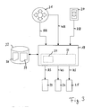
- FIG. 3 shows an exemplary embodiment of an electronically implemented inventive device Device for controlling the discharge elbow 2.
- One central part of this device forms a computer unit 19, for example a microcontroller, which via a user interface 21, 20 from User entered control commands AB, WB, HB for height adjustment the ejection elbow 2, for pivoting the discharge elbow 2 about the vertical axis of rotation 3 and for adjusting a discharge side on Chute 2 attached discharge flap 7 receives.
- a computer unit 19 for example a microcontroller, which via a user interface 21, 20 from User entered control commands AB, WB, HB for height adjustment the ejection elbow 2, for pivoting the discharge elbow 2 about the vertical axis of rotation 3 and for adjusting a discharge side on Chute 2 attached discharge flap 7 receives.
- the user interface 20, 21 has a rocker button 20 for height adjustment of the discharge chute 2. Depending on whether the operator this rocker button 20 tilted up or down, is a corresponding Height position control command HB forwarded to the computer unit 19. Furthermore
- the user interface 20, 21 has a multi-directional key 21 on which can be tilted in four directions. This multi-directional button 21 may for example be integrated in a multi-function handle, so that the driver simply operate the multi-directional button 21 with his thumb can.
- a rocker to the right or left is a corresponding Pivoting angle control command WB generates around the chute 2 after right or left to pivot about the vertical axis of rotation 3.
- a control command AB, WB, coming from the user interface 20, 21, HB is initially processed internally in the computer unit 19.
- the computer unit 19 then outputs a corresponding control signal AS, WS, HS to a height position adjusting device 25, a Schwenkwinkelstell Road 24 or to an ejection flap actuator 23 from.
- acts it is the height position adjusting device 25 and the ejection flap adjusting device 23 to valves which each drive hydraulic cylinders 10, 18, with which the discharge chute 2 about the horizontal axis 4 and the discharge flap 7 are tilted with respect to the discharge chute 2.
- Figure 2 are the two hydraulic cylinders 10, 18 for adjusting the height adjustment the ejection elbow 2 and for adjusting the discharge side the discharge chute 2 arranged discharge flap 7 clearly visible.
- the swivel angle adjusting device 24 for pivoting the discharge chute 2 about the vertical axis 3 is usually a hydraulic pump, which electrohydraulically an amount of oil on a hydraulic motor There, the output side by means of a worm wheel in a turntable 8 of the discharge elbow 2 engages and thus the discharge elbow 2 pivoted.
- the pivoting direction is determined by the direction of rotation of the Hydraulic motor specified. But instead of the hydraulic motor can also a stepper motor or the like can be used, which directly with the appropriate electrical actuating signals is controlled.
- control signals emanating from the computer unit 19 AS, WS, HS possibly still to the respective adjusting devices 23, 24, 25 adapted, for example, from a digital to an analog form have to be converted.
- the required facilities are here but not shown for clarity. You can both part the computer unit 19 as well as parts of the user interface 20, 21 and the individual adjusting devices 23, 24, 25 be. It can also be separate Units, each between the user interface 20, 21, the computer unit 19 and the respective adjusting devices 23, 24, 25 be switched.
- control device 26 For controlling the ejection elbow 2, the control device 26 operates according to FIG. 3 as follows:
- the control unit 26 Based on the known height adjustment of the discharge chute 2 are from the control unit 26 first the associated swivel range limit values detected. This can be done, for example, by reading a table 28 carried out in a connected to the computer unit 19 memory 22nd is deposited. In this table 28 are for each possible height adjustment the swivel range limits are listed. This table can be from the Control unit 26 are searched in any way. You can not only for a certain height adjustment, the swivel range limits can be determined, but it can also be determined, which height adjustment must be approached to certain pan range limits to reach.
- a swivel angle control command WB for pivoting the discharge chute 2 to the vertical Axis enters is based on this control command WB first from the Control unit 26 determines whether the approached from the chute 2 Swivel angle within the determined for the respective height adjustment Pivoting range limits. If this is the case, then a corresponding Angle control signal WS output to the pivot angle adjusting device 24. If, however, it is determined that the approaching swivel angle outside the swivel range limit values specified in the current height setting There are two different options.
- the control unit 26 using the table 28, the nearest Find height adjustment, which is a sufficiently large Swivel range has.
- the control unit 26 then gives corresponding Schwenkwinkelstellsignale WS and height position adjustment signals HS to the Schwenkwinkelstell issued 24 and the height position adjusting 25th off, so that the desired angle of the driver is approached and at the same time the spout 2 to the required path is pivoted upward, so that a collision with the cab 5 is avoided.
- the change in height adjustment can be continuous or gradually. In the second variant this function is overridden and it is only as long as a Schwenkwinkelstellsignal WS to the Schwenkwinkelstell responded 24 issued until the chute 2 the intended for the respective height adjustment swivel range limits has reached. An automatic height adjustment by the Control unit 26 does not take place in this mode.
- control unit 26 it is possible for the control unit 26 to be between the various Modify modes, so that, for example, a normal automatic adjustment of height adjustment to achieve a desired Swivel angle is performed and the driver aware of this Mode can issue when, for example, in adverse wind conditions and in dry crop such.
- Grass to avoid Harvest crops prefer the chute 2 as possible under all circumstances close above the loading edge of the transport vehicle 30 would like to keep and waived for an optimal arrangement of the observation area.
- the device 26 an automatic ejection flap control unit 27.
- This eject flap controller 27 is here in the form of a software module 27, for example as a subroutine the control unit 26, realized on the computer unit 19. For this is again referred to the figure 1.
- both the Throw 35 and the Kochladeabstand 36 shown graphically.
- the Throwing distance 35 is defined here as the distance of the vertical axis of rotation 3 the discharge chute 2 to the impact point 34 of the flow of material within the by the height of the loading edges of the transport vehicle 32 defined impact level.
- the overcharge distance 36 is defined as the distance of the impact point 34 from the through the vertical axis of rotation 3 of the discharge chute 2 extending longitudinal axis of the forage harvester 1.
- the Studentsladeabstand 36 thus specifies the distance in which the transport vehicle 32 must move parallel to the forage harvester 1.
- Impact point 34 or the definition of the impact point 34 here defined impact level at the level of the loading edge of the transport trailer 32nd is chosen arbitrarily. It can also be a hit on the field floor 39 or be defined on a freely chosen arbitrary level.
- the Studentsladeabstand 36 also with respect to any line or Position can be defined on the forage harvester 1.
- the pivoting of the Ejection elbow 2 from the first position 1 to the second position II the Throw 35 can be extended considerably to the same overload distance 36 to come. This is partly due to the compulsory Higher pivoting of the discharge chute 2 compensated. Incidentally, must an adjustment of the throwing distance 35 by a pivoting of the ejection flap 7 take place at the discharge end of the discharge elbow 2.
- this automatic ejection flap control unit 27th can be advantageously switched off by the driver at any time, so that he request by raising the discharge elbow 2 arbitrary Overload distance 36 may vary without this being counter-controlled the discharge flap 7 is compensated. Also, anytime over the multi-directional key 21 is a manual override of the ejection flap. 7 Such a manual change of the position of the Discharge flap 7 leads to a new transfer distance 36. The new transfer distance 36 then serves as the basis for the subsequent automatic Tracking.
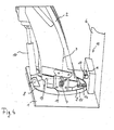
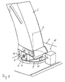
- Figures 4 and 5 show an electromechanically realized variant of a according to the invention automatic control of the height adjustment of Chute 2 depending on the set swivel angle the vertical axis 3.
- Discharge elbow 2 At the lower end of the pivotable about the horizontal axis 4 Discharge elbow 2 an approximately 3 ⁇ 4 circular running around the turntable 8 Backdrop 11 arranged.
- the backdrop 11 is here via connecting webs 14 coupled to the lower end of the discharge chute 2 and is performed on the turntable 8, that at a pivoting of the Chute 2 about the horizontal axis 4 down inevitably the Setting 11 parallel to the turntable 8 is moved up and the Setting 11 at a pivoting of the discharge chute 2 with the vertical Axis 3 turns.
- the gate 11 has end stops 13 and in a region at a distance in front of the stops 13 each have a ramp 12 on.
- a sensing device 15 fixedly arranged which has a sensing roller 17, which via a lever 16 with a Adjusting axis of a here within a housing arranged rotary potentiometer (not visible) is connected.
- This rotary potentiometer gives a rotation of the adjusting axis an actuating signal to a hydraulic valve (also not shown), which in turn a hydraulic cylinder 10 for Pivoting the discharge chute 2 to the horizontal axis 4 drives.
- the lever 16 is spring-loaded in the illustrated rest position held.
- the device according to FIGS. 4 and 5 functions in such a way that at a lowering of the discharge chute 2 in a lower position automatically the backdrop 11 is raised so far that the sensing roller 17 of the Sensing device 15 on the upper edge 9 of the gate 11 rolls along. Becomes then the chute 2 by means of the turntable 8 to the vertical Axis 3 pivots, so the follower roller 17 is approximately in a position in the ejection elbow 2 is a vertical pivot angle position to the harvesting vehicle 1 has reached, against the ramp 12 of the gate 11, whereby the feeler roller 17 is pushed upwards.
- the sensing device 15 is in this case constructed so that at a Stopping the sensing roller 17 to the respective stop 13 generates a signal is, which stops the pivoting about the vertical axis 3. That is, the sensing device 15 has the same function as a Limit switch.
Landscapes
- Life Sciences & Earth Sciences (AREA)
- Environmental Sciences (AREA)
- Harvester Elements (AREA)
- Loading Or Unloading Of Vehicles (AREA)
Abstract
Description
- 1
- Erntemaschine (Feldhäcksler)
- 2
- Überladeeinrichtung (Auswurfkrümmer)
- 3
- vertikale Achse
- 4
- horizontale Achse
- 5
- Gehäuseteil (Fahrerkabine)
- 6
- Kabinenrückwand
- 7
- Auswurfklappe
- 8
- Drehkranz
- 9
- Oberkante
- 10
- Hubzylinder
- 11
- Kulisse
- 12
- Auflaufschräge
- 13
- Anschlag
- 14
- Verbindungssteg
- 15
- Tasteinrichtung
- 16
- Hebel
- 17
- Tastrolle
- 18
- Hubzylinder
- 19
- Rechnereinheit
- 20
- Wipptaste
- 21
- Multirichtungstaste
- 22
- Speicher
- 23
- Auswurfklappenstelleinrichtung
- 24
- Schwenkwinkelstelleinrichtung
- 25
- Höhenpositionsstelleinrichtung
- 26
- Steuereinheit
- 27
- Auswurfklappensteuereinheit
- 28
- Tabelle
- 29
- Datenfeld
- 30
- Transportfahrzeug
- 31
- Zugmaschine
- 32
- Transportanhänger
- 33
- Pickup-Vorsatzgerät
- 34
- Auftreffpunkt
- 35
- Wurfweite
- 36
- Überladeabstand
- 37
- Fahrtrichtung
- 38
- Grasschwaden
- 39
- Feldboden
- AB
- Auswurfklappensteuerbefehl
- WB
- Schwenkwinkelsteuerbefehl
- HB
- Höhenpositionssteuerbefehl
- AS
- Auswurfklappenstellsignal
- WS
- Schwenkwinkelstellsignal
- HS
- Höhenpositionsstellsignal
Claims (17)
- Vorrichtung zur Steuerung einer Überladeeinrichtung (2) an einer Erntemaschine (1), wobei die Überladeeinrichtung (2) um eine vertikale Achse (3) sowie zur Veränderung der Höheneinstellung um eine horizontale Achse (4) schwenkbar in einem Abstand neben einem Gehäuseteil (5) der Erntemaschine (1) angeordnet ist,
mit Schwenkbereichbegrenzungsmitteln (11, 15, 19, 26, 28), welche den maximal zulässigen Schwenkbereich der Überladeeinrichtung (2) um die vertikale Achse (3) in Richtung des Gehäuseteils (5) zur Vermeidung einer Kollision mit dem Gehäuseteil (5) begrenzen,
dadurch gekennzeichnet, dass
die Schwenkbereichbegrenzungsmittel (11, 15, 19, 26, 28) derart ausgebildet und/oder angeordnet sind, dass der zulässige Schwenkbereich in Abhängigkeit von der Höheneinstellung der Überladeeinrichtung (2) bestimmt ist. - Vorrichtung nach Anspruch 1, dadurch gekennzeichnet, dass die Schwenkbereichbegrenzungsmittel (11, 15, 19, 26, 28) derart ausgebildet und/oder angeordnet sind, dass die Überladeeinrichtung (2) bei einer Verschwenkung in Richtung des Gehäuseteils (5) über den bei einer bestimmten Höheneinstellung der Überladeeinrichtung (2) festgelegten maximal zulässigen Schwenkbereich hinaus automatisch um zumindest eine horizontale Achse (3) in vertikaler Richtung höher geschwenkt wird.
- Vorrichtung nach Anspruch 1 oder 2, dadurch gekennzeichnet, dass die Schwenkbereichbegrenzungsmittel (11, 15, 19, 26, 28) derart ausgebildet und/oder angeordnet sind, dass mit zunehmender Höheneinstellung der Überladeeinrichtung (2) kontinuierlich der maximal zulässige Schwenkbereich erweitert wird.
- Vorrichtung nach Anspruch 1 oder 2, dadurch gekennzeichnet, dass die Schwenkbereichbegrenzungsmittel derart ausgebildet und/oder angeordnet sind, dass mit zunehmender Höheneinstellung der Überladeeinrichtung stufenweise der maximal zulässige Schwenkbereich erweitert wird.
- Vorrichtung nach einem der Ansprüche 1 bis 4, gekennzeichnet durchumfassen.Mittel zur Ermittlung eines Höhenpositionswerts, welcher die Höheneinstellung der Überladeeinrichtung (2) repräsentiert,eine Benutzerschnittstelle (21) zur Erzeugung eines Schwenkwinkelsteuerbefehls (WB) zur Verschwenkung der Überladeeinrichtung (2) um die vertikale Achse (3),und eine Steuereinheit (26), welche auf Basis des Höhenpositionswerts Grenzwerte für den zugehörigen maximal zulässigen Schwenkbereich ermittelt und auf Basis des Schwenkwinkelsteuerbefehls (WB) und unter Berücksichtigung der Schwenkbereichsgrenzwerte ein Schwenkwinkelstellsignal (WS) an eine Schwenkwinkelstelleinrichtung (24) zur entsprechenden Verschwenkung der Überladeeinrichtung (2) um die vertikale Achse (3) ausgibt,
- Vorrichtung nach Anspruch 5, dadurch gekennzeichnet, dass die Steuereinheit (26) Mittel aufweist, um - sofern ein durch einen empfangenen Schwenkwinkelsteuerbefehl (WB) repräsentierter Schwenkwinkel außerhalb der ermittelten Schwenkbereichsgrenzwerte liegt - ein Höhenpositionsstellsignal (HS) an eine Höhenpositionsstelleinrichtung (25) zur Verschwenkung der Überladeeinrichtung (2) um die horizontale Achse (4) auszugeben und die Überladeeinrichtung (2) in eine Höheneinstellung mit einem weiteren Schwenkbereich zu verfahren.
- Vorrichtung nach Anspruch 3, dadurch gekennzeichnet, dass die Schwenkbereichsbegrenzungsmittel (11, 15) eine Kulisse (11) und eine Abtasteinrichtung (15) umfassen, welche zumindest in einem Höheneinstellungsbereich der Überladeeinrichtung (2) bei einer Verschwenkung der Überladeeinrichtung (2) um die vertikale Achse (3) zumindest bereichsweise entlang der Kulisse (11) verfährt, wodurch die Überladeeinrichtung (2) bei einer Verschwenkung um die vertikale Achse (3) in Richtung des Gehäuseteils (5) zwangsläufig um die horizontale Achse (4) höhergeschwenkt wird.
- Vorrichtung nach Anspruch 7, dadurch gekennzeichnet, dass die Abtasteinrichtung (15) ein Steuerelement aufweist, welches eine Stelleinrichtung zur Verschwenkung der Überladeeinrichtung (2) um die horizontale Achse (4) ansteuert.
- Vorrichtung nach Anspruch 4, dadurch gekennzeichnet, dass die Schwenkbereichsbegrenzungsmittel unter Festlegung unterschiedlich weiter Schwenkbereiche mehrere stufenartig angeordnete mechanische Anschläge und/oder Endschalter aufweisen, so dass die Überladeeinrichtung bei einer Verschwenkung um die vertikale Achse in Richtung des Gehäuseteils in unterschiedlichen Höheneinstellungen jeweils gegen verschiedene der Anschläge und/oder Endschalter fährt.
- Vorrichtung nach Anspruch 9, dadurch gekennzeichnet, dass zumindest ein Teil der Endschalter so mit einer Stelleinrichtung zur Verschwenkung der Überladeeinrichtung um die horizontale Achse verschaltet ist, dass die Überladeeinrichtung bei einer Verschwenkung um die vertikale Achse gegen einen der Endschalter um ein bestimmtes Maß nach oben verschwenkt wird.
- Vorrichtung nach einem der Ansprüche 1 bis 10, dadurch gekennzeichnet, dass die Überladeeinrichtung (2) abgabeseitig eine verstellbare Auswurfklappe (7) aufweist und dass die Vorrichtung Steuermittel (27, 29) aufweist, um die Auswurfklappe (7) bei einer Verschwenkung der Überladeeinrichtung (2) um die vertikale und/oder horizontale Achse (3, 4) automatisch derart anzusteuern, dass ein vor der Verschwenkung eingestellter Überladeabstand (36) konstant bleibt.
- Vorrichtung zur Steuerung einer um eine vertikale und/oder horizontale Achse (3, 4) schwenkbar an einer Erntemaschine (1) angeordneten Überladeeinrichtung (2), welche abgabeseitig eine verstellbare Auswurfklappe (7) aufweist,
dadurch gekennzeichnet, dass die Vorrichtung Steuermittel (27, 29) aufweist, um die Auswurfklappe (7) bei einer Verschwenkung der Überladeeinrichtung (2) um die vertikale und/oder horizontale Achse (3, 4) automatisch derart anzusteuern, dass ein vor der Verschwenkung eingestellter Überladeabstand (36) im Wesentlichen konstant bleibt. - Erntemaschine (1) mit einer daran schwenkbar angeordneten Überladeeinrichtung (2) und mit einer Vorrichtung zur Steuerung der Überladeeinrichtung (2) nach einem der Ansprüche 1 bis 12.
- Verfahren zur Steuerung einer Überladeeinrichtung (2) an einer Erntemaschine (1), bei welchem die Überladeeinrichtung (2) um eine vertikale Achse (3) sowie zur Veränderung einer Höheneinstellung um eine horizontale Achse (4) schwenkbar in einem Abstand neben einem Gehäuseteil (5) der Erntemaschine (1) an der Erntemaschine (1) angeordnet ist,
und bei welchem der zulässige Schwenkbereich der Überladeeinrichtung (2) um die vertikale Achse (3) in Richtung des Gehäuseteils (5) zur Vermeidung einer Kollision mit dem Gehäuseteil (5) begrenzt wird,
dadurch gekennzeichnet, dass
der zulässige Schwenkbereich in Abhängigkeit von der Höheneinstellung der Überladeeinrichtung (2) bestimmt wird. - Verfahren nach Anspruch 14, dadurch gekennzeichnet, dass die Überladeeinrichtung (2) bei einer Verschwenkung in Richtung des Gehäuseteils (5) über den bei einer aktuellen Höheneinstellung der Überladeeinrichtung (2) festgelegten zulässigen Schwenkbereich hinaus automatisch um zumindest eine horizontale Achse (4) höher geschwenkt wird.
- Verfahren zur Steuerung einer um eine vertikale und/oder horizontale Achse (3, 4) schwenkbar an einer Erntemaschine (1) angeordneten Überladeeinrichtung (2), welche abgabeseitig eine verstellbare Auswurfklappe (7) aufweist, dadurch gekennzeichnet, dass
die Auswurfklappe (7) bei einer Verschwenkung der Überladeeinrichtung (2) um die vertikale und/oder horizontale Achse (3, 4) derart verstellt wird, dass ein vor der Verschwenkung eingestellter Überladeabstand (36) konstant bleibt. - Verfahren nach Anspruch 16, dadurch gekennzeichnet, dass auf Basis eines Höhenpositionswerts, welcher die Höheneinstellung der Überladeeinrichtung (2) repräsentiert, eines Schwenkwinkelpositionswerts, welcher die Winkelposition der Überladeeinrichtung (2) bezüglich der vertikalen Schwenkachse repräsentiert, und eines Auswurfklappenpositionswerts, welcher die Stellung der Auswurfklappe (7) repräsentiert, der aktuelle Überladeabstand (36) ermittelt wird,
und dass bei einer Verschwenkung der Überladeeinrichtung (2) um die vertikale und/oder horizontale Achse (3, 4) anhand des neuen Höhenpositionswerts und des neuen Schwenkwinkelpositionswerts sowie des zuvor ermittelten Überladeabstands (36), die erforderliche Auswurfklappenposition ermittelt und die Auswurfklappe (7) automatisch in diese Position gestellt wird.
Applications Claiming Priority (2)
| Application Number | Priority Date | Filing Date | Title |
|---|---|---|---|
| DE10240219A DE10240219A1 (de) | 2002-08-28 | 2002-08-28 | Vorrichtung zur Steuerung einer Überladeeinrichtung |
| DE10240219 | 2002-08-28 |
Publications (4)
| Publication Number | Publication Date |
|---|---|
| EP1393613A2 true EP1393613A2 (de) | 2004-03-03 |
| EP1393613A3 EP1393613A3 (de) | 2006-09-13 |
| EP1393613B1 EP1393613B1 (de) | 2009-01-14 |
| EP1393613B2 EP1393613B2 (de) | 2016-06-29 |
Family
ID=31197548
Family Applications (1)
| Application Number | Title | Priority Date | Filing Date |
|---|---|---|---|
| EP03015853.9A Expired - Lifetime EP1393613B2 (de) | 2002-08-28 | 2003-07-11 | Vorrichtung zur Steuerung einer Überladeeinrichtung |
Country Status (4)
| Country | Link |
|---|---|
| US (1) | US6932554B2 (de) |
| EP (1) | EP1393613B2 (de) |
| DE (2) | DE10240219A1 (de) |
| RU (1) | RU2324323C2 (de) |
Cited By (9)
| Publication number | Priority date | Publication date | Assignee | Title |
|---|---|---|---|---|
| EP1752037A1 (de) * | 2005-08-12 | 2007-02-14 | CLAAS Selbstfahrende Erntemaschinen GmbH | Verfahren zum Überladen von Erntegut |
| EP1894463A1 (de) * | 2006-08-28 | 2008-03-05 | CLAAS Selbstfahrende Erntemaschinen GmbH | Landwirtschaftliche Erntemaschine mit einer Überladeeinrichtung |
| US7343726B2 (en) | 2004-04-24 | 2008-03-18 | Deere & Company | Harvesting machine with a discharge assembly |
| EP1454520B1 (de) * | 2003-03-06 | 2008-11-19 | Deere & Company | Austrageinrichtung einer landwirtschaftlichen Erntemaschine |
| DE102009042371A1 (de) | 2009-09-23 | 2011-03-24 | Claas Selbstfahrende Erntemaschinen Gmbh | Vorrichtung zur Positionserfassung einer gegenüber einem Maschinengehäuse einer Erntemaschine um eine Schwenkachse schwenkbaren Überladeeinrichtung |
| RU2476061C2 (ru) * | 2007-04-04 | 2013-02-27 | КЛААС Зельбстфаренде Эрнтемашинен ГмбХ | Самоходная уборочная сельхозмашина с управляемым перегрузочным устройством |
| EP3069596A1 (de) * | 2015-03-17 | 2016-09-21 | CLAAS Selbstfahrende Erntemaschinen GmbH | Feldhäcksler |
| BE1027478A1 (de) | 2019-08-23 | 2021-03-02 | Deere & Co | Feldhäcksler mit Auswurfkrümmer und positionsverstellbarer Kabine |
| DE102021105212A1 (de) | 2021-03-04 | 2022-09-08 | Deere & Company | Steuersystem zur Steuerung eines beweglichen Elements einer Erntemaschine |
Families Citing this family (87)
| Publication number | Priority date | Publication date | Assignee | Title |
|---|---|---|---|---|
| DE102004052298A1 (de) * | 2004-10-06 | 2006-06-08 | Claas Selbstfahrende Erntemaschinen Gmbh | Überladeassistenzsystem |
| DE102006030986B4 (de) * | 2006-07-03 | 2012-01-19 | Edscha Engineering Gmbh | Vorrichtung und Verfahren zur Steuerung einer Fahrzeugklappe oder einer Fahrzeugtür |
| DE102007036799A1 (de) * | 2007-08-03 | 2009-02-05 | Claas Selbstfahrende Erntemaschinen Gmbh | Erntemaschine mit verstellbarer Überladeeinrichtung |
| DE102008015277A1 (de) * | 2008-03-20 | 2009-09-24 | Deere & Company, Moline | Verfahren und Vorrichtung zur Lenkung einer zweiten landwirtschaftlichen Maschine, die relativ zu einer ersten landwirtschaftlichen Maschine über ein Feld lenkbar ist |
| EP2138027B9 (de) * | 2008-06-25 | 2018-10-24 | CLAAS E-Systems KGaA mbH & Co KG | Übertragungsvorrichtung und landwirtschaftliches Fahrzeug |
| US8398469B2 (en) * | 2008-07-09 | 2013-03-19 | Deere & Company | Agricultural work machine having an unloading system for unloading an agricultural product |
| US8180534B2 (en) * | 2008-09-18 | 2012-05-15 | Deere & Company | Multiple harvester unloading system |
| EP2197171A3 (de) * | 2008-12-10 | 2014-06-25 | CLAAS Selbstfahrende Erntemaschinen GmbH | Verfahren zur Unterstützung der Automatisierung landwirtschaftlicher Leistungen |
| DE102009027245A1 (de) * | 2009-06-26 | 2010-12-30 | Deere & Company, Moline | Steueranordnung zur Kontrolle des Überladens landwirtschaftlichen Ernteguts von einer Erntemaschine auf ein Transportfahrzeug |
| EP2311307B1 (de) * | 2009-09-07 | 2011-12-07 | CLAAS Agrosystems GmbH & Co. KG | Füllstärkemessgerät, landwirtschaftliches Fahrzeug mit solch einem Messgerät und Verfahren zur Steuerung der Befüllung eines Zielbereichs |
| ATE533350T1 (de) * | 2009-09-07 | 2011-12-15 | Claas Agrosystems Gmbh & Co Kg | Steuerungssystem eines landwirtschaftlichen fahrzeugs mit einem güterträger, landwirtschaftliches fahrzeug und verfahren zur steuerung eines güterträgers des landwirtschaftlichen fahrzeugs |
| BE1019192A3 (nl) * | 2010-02-21 | 2012-04-03 | Cnh Belgium Nv | Werkwijze voor het richten van een ontlaadtoestel van een oogstmachine naar een container. |
| DE102010017459A1 (de) * | 2010-06-18 | 2011-12-22 | Claas Selbstfahrende Erntemaschinen Gmbh | Landwirtschaftliche Erntemaschine |
| US8789563B2 (en) * | 2010-10-12 | 2014-07-29 | Deere & Company | Intelligent grain bag loader |
| US20120240795A1 (en) * | 2010-12-28 | 2012-09-27 | Agco Corporation | Roller Bale Chute Accumulation |
| AU2011359328B2 (en) * | 2011-02-18 | 2015-06-11 | Cnh Industrial America Llc | System and method for trajectory control of a transport vehicle used with a harvester |
| ES2390150B1 (es) * | 2011-03-08 | 2013-09-18 | Recuperación Medioambientales Industriales, S.L. | Ecoinstalación para llenado automático de contenedores de chatarra y procedimiento de llenado. |
| DE102011002071A1 (de) * | 2011-04-15 | 2012-10-18 | Claas Selbstfahrende Erntemaschinen Gmbh | System und Verfahren zur Steuerung der Erntegutüberladung |
| DE102011050629A1 (de) * | 2011-05-25 | 2012-11-29 | Claas Selbstfahrende Erntemaschinen Gmbh | Erntevorrichtung |
| US9529364B2 (en) | 2014-03-24 | 2016-12-27 | Cnh Industrial America Llc | System for coordinating agricultural vehicle control for loading a truck |
| US9763377B2 (en) * | 2014-05-22 | 2017-09-19 | Yanmar Co., Ltd. | Running system of work vehicle |
| US9635814B2 (en) * | 2014-07-17 | 2017-05-02 | Deere & Company | Strategic crop placement using a virtual trip line for a harvester and crop accumulator combination |
| US10000339B2 (en) * | 2015-07-02 | 2018-06-19 | Lockheed Martin Corporation | Gravity-fed housing for gasification system |
| DE102018201554A1 (de) | 2018-02-01 | 2019-08-01 | Deere & Company | Feldhäcksler mit einem Sensor zur Erkennung einer drohenden Verstopfung und Mitteln zur Behebung |
| US11672203B2 (en) | 2018-10-26 | 2023-06-13 | Deere & Company | Predictive map generation and control |
| US11178818B2 (en) | 2018-10-26 | 2021-11-23 | Deere & Company | Harvesting machine control system with fill level processing based on yield data |
| US11641800B2 (en) | 2020-02-06 | 2023-05-09 | Deere & Company | Agricultural harvesting machine with pre-emergence weed detection and mitigation system |
| US11079725B2 (en) | 2019-04-10 | 2021-08-03 | Deere & Company | Machine control using real-time model |
| US12069978B2 (en) | 2018-10-26 | 2024-08-27 | Deere & Company | Predictive environmental characteristic map generation and control system |
| US11467605B2 (en) | 2019-04-10 | 2022-10-11 | Deere & Company | Zonal machine control |
| US11957072B2 (en) | 2020-02-06 | 2024-04-16 | Deere & Company | Pre-emergence weed detection and mitigation system |
| US11589509B2 (en) | 2018-10-26 | 2023-02-28 | Deere & Company | Predictive machine characteristic map generation and control system |
| US11240961B2 (en) | 2018-10-26 | 2022-02-08 | Deere & Company | Controlling a harvesting machine based on a geo-spatial representation indicating where the harvesting machine is likely to reach capacity |
| US11653588B2 (en) | 2018-10-26 | 2023-05-23 | Deere & Company | Yield map generation and control system |
| US10966369B2 (en) | 2018-10-31 | 2021-04-06 | Cnh Industrial America Llc | System and method for calibrating alignment of work vehicles |
| US11399462B2 (en) | 2018-10-31 | 2022-08-02 | Cnh Industrial America Llc | System and method for calibrating alignment of work vehicles |
| US11778945B2 (en) | 2019-04-10 | 2023-10-10 | Deere & Company | Machine control using real-time model |
| US11234366B2 (en) | 2019-04-10 | 2022-02-01 | Deere & Company | Image selection for machine control |
| US12035648B2 (en) | 2020-02-06 | 2024-07-16 | Deere & Company | Predictive weed map generation and control system |
| US12329148B2 (en) | 2020-02-06 | 2025-06-17 | Deere & Company | Predictive weed map and material application machine control |
| US12225846B2 (en) | 2020-02-06 | 2025-02-18 | Deere & Company | Machine control using a predictive map |
| US11477940B2 (en) | 2020-03-26 | 2022-10-25 | Deere & Company | Mobile work machine control based on zone parameter modification |
| US12178158B2 (en) | 2020-10-09 | 2024-12-31 | Deere & Company | Predictive map generation and control system for an agricultural work machine |
| US11889788B2 (en) | 2020-10-09 | 2024-02-06 | Deere & Company | Predictive biomass map generation and control |
| US11675354B2 (en) | 2020-10-09 | 2023-06-13 | Deere & Company | Machine control using a predictive map |
| US12419220B2 (en) | 2020-10-09 | 2025-09-23 | Deere & Company | Predictive map generation and control system |
| US11874669B2 (en) | 2020-10-09 | 2024-01-16 | Deere & Company | Map generation and control system |
| US11849672B2 (en) | 2020-10-09 | 2023-12-26 | Deere & Company | Machine control using a predictive map |
| US12550802B2 (en) | 2020-10-08 | 2026-02-17 | Deere & Company | Predictive machine characteristic map generation and control system |
| US11650587B2 (en) | 2020-10-09 | 2023-05-16 | Deere & Company | Predictive power map generation and control system |
| US11871697B2 (en) | 2020-10-09 | 2024-01-16 | Deere & Company | Crop moisture map generation and control system |
| US11895948B2 (en) | 2020-10-09 | 2024-02-13 | Deere & Company | Predictive map generation and control based on soil properties |
| US11849671B2 (en) | 2020-10-09 | 2023-12-26 | Deere & Company | Crop state map generation and control system |
| US11983009B2 (en) | 2020-10-09 | 2024-05-14 | Deere & Company | Map generation and control system |
| US12069986B2 (en) | 2020-10-09 | 2024-08-27 | Deere & Company | Map generation and control system |
| US11825768B2 (en) | 2020-10-09 | 2023-11-28 | Deere & Company | Machine control using a predictive map |
| US11592822B2 (en) | 2020-10-09 | 2023-02-28 | Deere & Company | Machine control using a predictive map |
| US11927459B2 (en) | 2020-10-09 | 2024-03-12 | Deere & Company | Machine control using a predictive map |
| US11727680B2 (en) | 2020-10-09 | 2023-08-15 | Deere & Company | Predictive map generation based on seeding characteristics and control |
| US12422847B2 (en) | 2020-10-09 | 2025-09-23 | Deere & Company | Predictive agricultural model and map generation |
| US11864483B2 (en) | 2020-10-09 | 2024-01-09 | Deere & Company | Predictive map generation and control system |
| US11711995B2 (en) | 2020-10-09 | 2023-08-01 | Deere & Company | Machine control using a predictive map |
| US11635765B2 (en) | 2020-10-09 | 2023-04-25 | Deere & Company | Crop state map generation and control system |
| US11844311B2 (en) | 2020-10-09 | 2023-12-19 | Deere & Company | Machine control using a predictive map |
| US11946747B2 (en) | 2020-10-09 | 2024-04-02 | Deere & Company | Crop constituent map generation and control system |
| US11474523B2 (en) | 2020-10-09 | 2022-10-18 | Deere & Company | Machine control using a predictive speed map |
| US12386354B2 (en) | 2020-10-09 | 2025-08-12 | Deere & Company | Predictive power map generation and control system |
| US11845449B2 (en) | 2020-10-09 | 2023-12-19 | Deere & Company | Map generation and control system |
| US12013245B2 (en) | 2020-10-09 | 2024-06-18 | Deere & Company | Predictive map generation and control system |
| US11889787B2 (en) | 2020-10-09 | 2024-02-06 | Deere & Company | Predictive speed map generation and control system |
| US12250905B2 (en) | 2020-10-09 | 2025-03-18 | Deere & Company | Machine control using a predictive map |
| US12229886B2 (en) | 2021-10-01 | 2025-02-18 | Deere & Company | Historical crop state model, predictive crop state map generation and control system |
| US12310286B2 (en) | 2021-12-14 | 2025-05-27 | Deere & Company | Crop constituent sensing |
| US12302791B2 (en) | 2021-12-20 | 2025-05-20 | Deere & Company | Crop constituents, predictive mapping, and agricultural harvester control |
| US12245549B2 (en) | 2022-01-11 | 2025-03-11 | Deere & Company | Predictive response map generation and control system |
| US12520759B2 (en) | 2022-01-26 | 2026-01-13 | Deere & Company | Systems and methods for predicting material dynamics |
| US12082531B2 (en) | 2022-01-26 | 2024-09-10 | Deere & Company | Systems and methods for predicting material dynamics |
| DE102022103168A1 (de) * | 2022-02-10 | 2023-08-10 | Maschinenfabrik Bernard Krone GmbH & Co. KG | Bedienhebel zur Steuerung einer Komponente, Arbeitsmaschine mit dem Bedienhebel und Verfahren zum Steuern der Komponente |
| US12295288B2 (en) | 2022-04-05 | 2025-05-13 | Deere &Company | Predictive machine setting map generation and control system |
| US12358493B2 (en) | 2022-04-08 | 2025-07-15 | Deere & Company | Systems and methods for predictive power requirements and control |
| US12298767B2 (en) | 2022-04-08 | 2025-05-13 | Deere & Company | Predictive material consumption map and control |
| US12058951B2 (en) | 2022-04-08 | 2024-08-13 | Deere & Company | Predictive nutrient map and control |
| US12582035B2 (en) | 2022-04-08 | 2026-03-24 | Deere & Company | Systems and methods for predictive power requirements and control |
| US12284934B2 (en) | 2022-04-08 | 2025-04-29 | Deere & Company | Systems and methods for predictive tractive characteristics and control |
| US12604791B2 (en) | 2022-07-06 | 2026-04-21 | Deere & Company | Machine control based upon estimated operator skill level trend |
| CA3251707A1 (en) | 2022-08-11 | 2024-02-15 | Deere & Company | PREDICTIVE HARVEST LOGISTICS SYSTEMS AND PROCESSES |
| AU2022473991A1 (en) | 2022-08-11 | 2024-11-14 | Deere & Company | Systems and methods for predictive harvesting logistics |
Family Cites Families (14)
| Publication number | Priority date | Publication date | Assignee | Title |
|---|---|---|---|---|
| LU70952A1 (de) * | 1974-09-20 | 1975-03-06 | ||
| LU82173A1 (fr) * | 1980-02-15 | 1980-05-07 | Wurth Sa O | Dispositif de chargement pour fours a cuve |
| AT381832B (de) * | 1981-07-07 | 1986-12-10 | Poettinger Ohg Alois | Auswurfkruemmer fuer landwirtschaftliche maschinen |
| LU84303A1 (fr) * | 1982-07-28 | 1984-03-22 | Wurth Paul Sa | Procede et dispositif de commande du mouvement d'une goulotte oscillante et application a une installation de chargement d'un four a cuve |
| DE4403893A1 (de) * | 1994-02-08 | 1995-08-10 | Claas Ohg | Vorrichtung zur automatischen Befüllung von Ladebehältern mit einem Gutstrom |
| DE19531662A1 (de) * | 1995-08-29 | 1997-03-06 | Claas Ohg | Vorrichtung zum automatischen Befüllen von Ladebehältern |
| LU90295B1 (fr) * | 1998-10-06 | 2000-04-07 | Wurth Paul Sa | Dispositif de répartition de matières en vrac |
| DE19848127A1 (de) * | 1998-10-19 | 2000-04-20 | Claas Selbstfahr Erntemasch | Vorrichtung zur Steuerung einer Überladeeinrichtung |
| DE10021664B4 (de) * | 2000-05-04 | 2004-05-06 | Maschinenfabrik Bernard Krone Gmbh | Erntemaschine, insbesondere selbstfahrender Feldhäcksler |
| DE10021660C2 (de) * | 2000-05-04 | 2002-07-04 | Krone Bernhard Gmbh Maschf | Erntemaschine, insbesondere selbstfahrender Feldhäcksler |
| DE10064861A1 (de) * | 2000-12-23 | 2002-06-27 | Claas Selbstfahr Erntemasch | Vorrichtung und Verfahren zur automatischen Steuerung einer Überladeeinrichtung an landwirtschaftlichen Erntemaschinen |
| DE10064862A1 (de) * | 2000-12-23 | 2002-07-11 | Claas Selbstfahr Erntemasch | Vorrichtung und Verfahren zur Koordination und Einstellung von landwirtschaftlichen Fahrzeugen |
| US6578694B2 (en) * | 2001-02-16 | 2003-06-17 | Mcneilus Truck And Manufacturing, Inc. | Discharge chute control system |
| DE10119279A1 (de) * | 2001-04-20 | 2002-10-24 | Deere & Co | Einrichtung zur Steuerung der Position einer Austrageinrichtung einer landwirtschaftlichen Erntemaschine |
-
2002
- 2002-08-28 DE DE10240219A patent/DE10240219A1/de not_active Withdrawn
-
2003
- 2003-07-11 EP EP03015853.9A patent/EP1393613B2/de not_active Expired - Lifetime
- 2003-07-11 DE DE50311079T patent/DE50311079D1/de not_active Expired - Lifetime
- 2003-08-21 RU RU2003126441/11A patent/RU2324323C2/ru active
- 2003-08-28 US US10/650,527 patent/US6932554B2/en not_active Expired - Lifetime
Cited By (13)
| Publication number | Priority date | Publication date | Assignee | Title |
|---|---|---|---|---|
| EP1454520B1 (de) * | 2003-03-06 | 2008-11-19 | Deere & Company | Austrageinrichtung einer landwirtschaftlichen Erntemaschine |
| US7343726B2 (en) | 2004-04-24 | 2008-03-18 | Deere & Company | Harvesting machine with a discharge assembly |
| EP1752037A1 (de) * | 2005-08-12 | 2007-02-14 | CLAAS Selbstfahrende Erntemaschinen GmbH | Verfahren zum Überladen von Erntegut |
| EP1894463A1 (de) * | 2006-08-28 | 2008-03-05 | CLAAS Selbstfahrende Erntemaschinen GmbH | Landwirtschaftliche Erntemaschine mit einer Überladeeinrichtung |
| RU2476061C2 (ru) * | 2007-04-04 | 2013-02-27 | КЛААС Зельбстфаренде Эрнтемашинен ГмбХ | Самоходная уборочная сельхозмашина с управляемым перегрузочным устройством |
| EP2301319A1 (de) | 2009-09-23 | 2011-03-30 | CLAAS Selbstfahrende Erntemaschinen GmbH | Vorrichtung zur Positionserfassung einer gegenüber einem Maschinengehäuse einer Erntemaschine um eine Schwenkachse schwenkbaren Überladeeinrichtung |
| DE102009042371A1 (de) | 2009-09-23 | 2011-03-24 | Claas Selbstfahrende Erntemaschinen Gmbh | Vorrichtung zur Positionserfassung einer gegenüber einem Maschinengehäuse einer Erntemaschine um eine Schwenkachse schwenkbaren Überladeeinrichtung |
| EP3069596A1 (de) * | 2015-03-17 | 2016-09-21 | CLAAS Selbstfahrende Erntemaschinen GmbH | Feldhäcksler |
| BE1027478A1 (de) | 2019-08-23 | 2021-03-02 | Deere & Co | Feldhäcksler mit Auswurfkrümmer und positionsverstellbarer Kabine |
| BE1027478B1 (de) * | 2019-08-23 | 2021-07-26 | Deere & Co | Feldhäcksler mit Auswurfkrümmer und positionsverstellbarer Kabine |
| DE102021105212A1 (de) | 2021-03-04 | 2022-09-08 | Deere & Company | Steuersystem zur Steuerung eines beweglichen Elements einer Erntemaschine |
| BE1029116A1 (de) | 2021-03-04 | 2022-09-08 | Deere & Co | Steuersystem zur Steuerung eines beweglichen Elements einer Erntemaschine |
| BE1029116B1 (de) * | 2021-03-04 | 2022-12-16 | Deere & Co | Steuersystem zur Steuerung eines beweglichen Elements einer Erntemaschine |
Also Published As
| Publication number | Publication date |
|---|---|
| US20040116169A1 (en) | 2004-06-17 |
| EP1393613B2 (de) | 2016-06-29 |
| RU2003126441A (ru) | 2005-03-10 |
| EP1393613B1 (de) | 2009-01-14 |
| DE50311079D1 (de) | 2009-03-05 |
| RU2324323C2 (ru) | 2008-05-20 |
| DE10240219A1 (de) | 2004-03-11 |
| EP1393613A3 (de) | 2006-09-13 |
| US6932554B2 (en) | 2005-08-23 |
Similar Documents
| Publication | Publication Date | Title |
|---|---|---|
| EP1393613B2 (de) | Vorrichtung zur Steuerung einer Überladeeinrichtung | |
| DE60319618T2 (de) | Bildverarbeitung für Entladungsmittelkontrollsystem | |
| EP1454520B1 (de) | Austrageinrichtung einer landwirtschaftlichen Erntemaschine | |
| EP1405555B2 (de) | Verfahren zur Steuerung einer Überladeeinrichtung | |
| EP1808063B1 (de) | Selbstfahrende landwirtschaftliche Erntemaschine mit einem um eine vertikale Achse schwenkbaren Erntevorsatz | |
| DE10134137B4 (de) | Selbstfahrende landwirtschaftliche Erntemaschine | |
| DE102004052298A1 (de) | Überladeassistenzsystem | |
| EP2302995A1 (de) | Steueranordnung zur kontrolle des überladens landwirtschaftlichen ernteguts von einer erntemaschine auf ein transportfahrzeug | |
| EP1219159A1 (de) | Vorrichtung und Verfahren zur automatischen Steuerung einer Überladeeinrichtung an landwirtschaftlichen Erntemaschinen | |
| EP0843960A1 (de) | Vorrichtung zur Überwachung der Überladung von Gütern einer Arbeitsmaschine in einem Transportfahrzeug | |
| EP1338190B1 (de) | Verteilvorrichtung für aus einer Erntemaschine austretendes Häckselgut | |
| EP1250832B2 (de) | Einrichtung zur Steuerung der Position einer Austragseinrichtung einer landwirtschaftlichen Erntemaschine | |
| EP2020175A1 (de) | Erntemaschine mit verstellbarer Überladeeinrichtung | |
| DE10212722B4 (de) | Erntemaschine | |
| EP1588601B1 (de) | Erntemaschine mit einer Austrageinrichtung | |
| DE102019005662A1 (de) | Auswurfkrümmer für einen Feldhäcksler | |
| BE1026568B1 (de) | Selbstfahrende erntemaschine mit einer überladeeinrichtung | |
| EP1595434A1 (de) | Haspelzusammenbau | |
| BE1027478B1 (de) | Feldhäcksler mit Auswurfkrümmer und positionsverstellbarer Kabine | |
| EP4197308B1 (de) | Häckselausrüstung sowie arbeitszug mit häckselausrüstung | |
| EP3069596B1 (de) | Feldhäcksler | |
| EP2656723B1 (de) | Erntegutrestehäcksel und -verteilanordnung für einen Mähdrescher mit in eine Schwadablageposition verbringbaren Führungselementen |
Legal Events
| Date | Code | Title | Description |
|---|---|---|---|
| PUAI | Public reference made under article 153(3) epc to a published international application that has entered the european phase |
Free format text: ORIGINAL CODE: 0009012 |
|
| AK | Designated contracting states |
Kind code of ref document: A2 Designated state(s): AT BE BG CH CY CZ DE DK EE ES FI FR GB GR HU IE IT LI LU MC NL PT RO SE SI SK TR |
|
| AX | Request for extension of the european patent |
Extension state: AL LT LV MK |
|
| PUAL | Search report despatched |
Free format text: ORIGINAL CODE: 0009013 |
|
| AK | Designated contracting states |
Kind code of ref document: A3 Designated state(s): AT BE BG CH CY CZ DE DK EE ES FI FR GB GR HU IE IT LI LU MC NL PT RO SE SI SK TR |
|
| AX | Request for extension of the european patent |
Extension state: AL LT LV MK |
|
| 17P | Request for examination filed |
Effective date: 20070313 |
|
| AKX | Designation fees paid |
Designated state(s): BE DE FR GB |
|
| 17Q | First examination report despatched |
Effective date: 20071023 |
|
| GRAP | Despatch of communication of intention to grant a patent |
Free format text: ORIGINAL CODE: EPIDOSNIGR1 |
|
| GRAS | Grant fee paid |
Free format text: ORIGINAL CODE: EPIDOSNIGR3 |
|
| GRAA | (expected) grant |
Free format text: ORIGINAL CODE: 0009210 |
|
| AK | Designated contracting states |
Kind code of ref document: B1 Designated state(s): BE DE FR GB |
|
| REG | Reference to a national code |
Ref country code: GB Ref legal event code: FG4D Free format text: NOT ENGLISH |
|
| REF | Corresponds to: |
Ref document number: 50311079 Country of ref document: DE Date of ref document: 20090305 Kind code of ref document: P |
|
| PLBI | Opposition filed |
Free format text: ORIGINAL CODE: 0009260 |
|
| 26 | Opposition filed |
Opponent name: DEERE & COMPANY Effective date: 20090922 |
|
| PLAX | Notice of opposition and request to file observation + time limit sent |
Free format text: ORIGINAL CODE: EPIDOSNOBS2 |
|
| PLBB | Reply of patent proprietor to notice(s) of opposition received |
Free format text: ORIGINAL CODE: EPIDOSNOBS3 |
|
| REG | Reference to a national code |
Ref country code: FR Ref legal event code: PLFP Year of fee payment: 13 |
|
| PUAH | Patent maintained in amended form |
Free format text: ORIGINAL CODE: 0009272 |
|
| STAA | Information on the status of an ep patent application or granted ep patent |
Free format text: STATUS: PATENT MAINTAINED AS AMENDED |
|
| 27A | Patent maintained in amended form |
Effective date: 20160629 |
|
| AK | Designated contracting states |
Kind code of ref document: B2 Designated state(s): BE DE FR GB |
|
| REG | Reference to a national code |
Ref country code: DE Ref legal event code: R102 Ref document number: 50311079 Country of ref document: DE |
|
| REG | Reference to a national code |
Ref country code: FR Ref legal event code: PLFP Year of fee payment: 14 |
|
| REG | Reference to a national code |
Ref country code: FR Ref legal event code: PLFP Year of fee payment: 15 |
|
| REG | Reference to a national code |
Ref country code: FR Ref legal event code: PLFP Year of fee payment: 16 |
|
| PGFP | Annual fee paid to national office [announced via postgrant information from national office to epo] |
Ref country code: GB Payment date: 20180719 Year of fee payment: 16 |
|
| REG | Reference to a national code |
Ref country code: DE Ref legal event code: R084 Ref document number: 50311079 Country of ref document: DE |
|
| GBPC | Gb: european patent ceased through non-payment of renewal fee |
Effective date: 20190711 |
|
| PG25 | Lapsed in a contracting state [announced via postgrant information from national office to epo] |
Ref country code: GB Free format text: LAPSE BECAUSE OF NON-PAYMENT OF DUE FEES Effective date: 20190711 |
|
| PGFP | Annual fee paid to national office [announced via postgrant information from national office to epo] |
Ref country code: FR Payment date: 20210727 Year of fee payment: 19 |
|
| PGFP | Annual fee paid to national office [announced via postgrant information from national office to epo] |
Ref country code: DE Payment date: 20210721 Year of fee payment: 19 Ref country code: BE Payment date: 20210721 Year of fee payment: 19 |
|
| REG | Reference to a national code |
Ref country code: DE Ref legal event code: R119 Ref document number: 50311079 Country of ref document: DE |
|
| REG | Reference to a national code |
Ref country code: BE Ref legal event code: MM Effective date: 20220731 |
|
| PG25 | Lapsed in a contracting state [announced via postgrant information from national office to epo] |
Ref country code: FR Free format text: LAPSE BECAUSE OF NON-PAYMENT OF DUE FEES Effective date: 20220731 |
|
| PG25 | Lapsed in a contracting state [announced via postgrant information from national office to epo] |
Ref country code: DE Free format text: LAPSE BECAUSE OF NON-PAYMENT OF DUE FEES Effective date: 20230201 Ref country code: BE Free format text: LAPSE BECAUSE OF NON-PAYMENT OF DUE FEES Effective date: 20220731 |