EP1392960B1 - Process for dosing an additive into a fuel - Google Patents
Process for dosing an additive into a fuel Download PDFInfo
- Publication number
- EP1392960B1 EP1392960B1 EP02718362A EP02718362A EP1392960B1 EP 1392960 B1 EP1392960 B1 EP 1392960B1 EP 02718362 A EP02718362 A EP 02718362A EP 02718362 A EP02718362 A EP 02718362A EP 1392960 B1 EP1392960 B1 EP 1392960B1
- Authority
- EP
- European Patent Office
- Prior art keywords
- fuel
- additive
- process according
- dosing apparatus
- dosing
- Prior art date
- Legal status (The legal status is an assumption and is not a legal conclusion. Google has not performed a legal analysis and makes no representation as to the accuracy of the status listed.)
- Revoked
Links
Images






Classifications
-
- C—CHEMISTRY; METALLURGY
- C10—PETROLEUM, GAS OR COKE INDUSTRIES; TECHNICAL GASES CONTAINING CARBON MONOXIDE; FUELS; LUBRICANTS; PEAT
- C10L—FUELS NOT OTHERWISE PROVIDED FOR; NATURAL GAS; SYNTHETIC NATURAL GAS OBTAINED BY PROCESSES NOT COVERED BY SUBCLASSES C10G OR C10K; LIQUIFIED PETROLEUM GAS; USE OF ADDITIVES TO FUELS OR FIRES; FIRE-LIGHTERS
- C10L10/00—Use of additives to fuels or fires for particular purposes
- C10L10/06—Use of additives to fuels or fires for particular purposes for facilitating soot removal
-
- C—CHEMISTRY; METALLURGY
- C10—PETROLEUM, GAS OR COKE INDUSTRIES; TECHNICAL GASES CONTAINING CARBON MONOXIDE; FUELS; LUBRICANTS; PEAT
- C10L—FUELS NOT OTHERWISE PROVIDED FOR; NATURAL GAS; SYNTHETIC NATURAL GAS OBTAINED BY PROCESSES NOT COVERED BY SUBCLASSES C10G OR C10K; LIQUIFIED PETROLEUM GAS; USE OF ADDITIVES TO FUELS OR FIRES; FIRE-LIGHTERS
- C10L1/00—Liquid carbonaceous fuels
- C10L1/10—Liquid carbonaceous fuels containing additives
- C10L1/12—Inorganic compounds
- C10L1/1208—Inorganic compounds elements
-
- C—CHEMISTRY; METALLURGY
- C10—PETROLEUM, GAS OR COKE INDUSTRIES; TECHNICAL GASES CONTAINING CARBON MONOXIDE; FUELS; LUBRICANTS; PEAT
- C10L—FUELS NOT OTHERWISE PROVIDED FOR; NATURAL GAS; SYNTHETIC NATURAL GAS OBTAINED BY PROCESSES NOT COVERED BY SUBCLASSES C10G OR C10K; LIQUIFIED PETROLEUM GAS; USE OF ADDITIVES TO FUELS OR FIRES; FIRE-LIGHTERS
- C10L1/00—Liquid carbonaceous fuels
- C10L1/10—Liquid carbonaceous fuels containing additives
- C10L1/14—Organic compounds
- C10L1/30—Organic compounds compounds not mentioned before (complexes)
-
- F—MECHANICAL ENGINEERING; LIGHTING; HEATING; WEAPONS; BLASTING
- F02—COMBUSTION ENGINES; HOT-GAS OR COMBUSTION-PRODUCT ENGINE PLANTS
- F02D—CONTROLLING COMBUSTION ENGINES
- F02D19/00—Controlling engines characterised by their use of non-liquid fuels, pluralities of fuels, or non-fuel substances added to the combustible mixtures
- F02D19/12—Controlling engines characterised by their use of non-liquid fuels, pluralities of fuels, or non-fuel substances added to the combustible mixtures peculiar to engines working with non-fuel substances or with anti-knock agents, e.g. with anti-knock fuel
-
- F—MECHANICAL ENGINEERING; LIGHTING; HEATING; WEAPONS; BLASTING
- F02—COMBUSTION ENGINES; HOT-GAS OR COMBUSTION-PRODUCT ENGINE PLANTS
- F02M—SUPPLYING COMBUSTION ENGINES IN GENERAL WITH COMBUSTIBLE MIXTURES OR CONSTITUENTS THEREOF
- F02M25/00—Engine-pertinent apparatus for adding non-fuel substances or small quantities of secondary fuel to combustion-air, main fuel or fuel-air mixture
-
- B—PERFORMING OPERATIONS; TRANSPORTING
- B60—VEHICLES IN GENERAL
- B60K—ARRANGEMENT OR MOUNTING OF PROPULSION UNITS OR OF TRANSMISSIONS IN VEHICLES; ARRANGEMENT OR MOUNTING OF PLURAL DIVERSE PRIME-MOVERS IN VEHICLES; AUXILIARY DRIVES FOR VEHICLES; INSTRUMENTATION OR DASHBOARDS FOR VEHICLES; ARRANGEMENTS IN CONNECTION WITH COOLING, AIR INTAKE, GAS EXHAUST OR FUEL SUPPLY OF PROPULSION UNITS IN VEHICLES
- B60K15/00—Arrangement in connection with fuel supply of combustion engines or other fuel consuming energy converters, e.g. fuel cells; Mounting or construction of fuel tanks
- B60K15/03—Fuel tanks
- B60K2015/03328—Arrangements or special measures related to fuel tanks or fuel handling
- B60K2015/03348—Arrangements or special measures related to fuel tanks or fuel handling for supplying additives to fuel
-
- Y—GENERAL TAGGING OF NEW TECHNOLOGICAL DEVELOPMENTS; GENERAL TAGGING OF CROSS-SECTIONAL TECHNOLOGIES SPANNING OVER SEVERAL SECTIONS OF THE IPC; TECHNICAL SUBJECTS COVERED BY FORMER USPC CROSS-REFERENCE ART COLLECTIONS [XRACs] AND DIGESTS
- Y02—TECHNOLOGIES OR APPLICATIONS FOR MITIGATION OR ADAPTATION AGAINST CLIMATE CHANGE
- Y02T—CLIMATE CHANGE MITIGATION TECHNOLOGIES RELATED TO TRANSPORTATION
- Y02T10/00—Road transport of goods or passengers
- Y02T10/10—Internal combustion engine [ICE] based vehicles
- Y02T10/12—Improving ICE efficiencies
-
- Y—GENERAL TAGGING OF NEW TECHNOLOGICAL DEVELOPMENTS; GENERAL TAGGING OF CROSS-SECTIONAL TECHNOLOGIES SPANNING OVER SEVERAL SECTIONS OF THE IPC; TECHNICAL SUBJECTS COVERED BY FORMER USPC CROSS-REFERENCE ART COLLECTIONS [XRACs] AND DIGESTS
- Y10—TECHNICAL SUBJECTS COVERED BY FORMER USPC
- Y10T—TECHNICAL SUBJECTS COVERED BY FORMER US CLASSIFICATION
- Y10T137/00—Fluid handling
- Y10T137/2496—Self-proportioning or correlating systems
- Y10T137/2514—Self-proportioning flow systems
- Y10T137/2521—Flow comparison or differential response
- Y10T137/2526—Main line flow displaces or entrains material from reservoir
Definitions
- the present invention relates to a process for dosing an additive in to a fuel.
- Iron based fuel soluble additives are known to be effective in this way.
- SAE 980539 presented at the SAE International Congress and Exposition in Detroit in February 1998, Mayer describes iron based fuel soluble additives as having a catalytic effect on the bum out of soot trapped in a DPF. Mayer also mentions additives based on cerium and copper for catalytic effect, and indicates that these additives were commercially available for use with DPFs in 1998.
- An alternative and preferred method is to produce an organo-metallic chemical compound soluble in the hydrocarbon fuel.
- This method is preferred because combining the desired metal ion with a suitable organic molecule, which is soluble in the hydrocarbon diesel fuel, allows the desired metal to be introduced in molecular form into the combustion chamber.
- production cars made by PSA Ford Citroen in France rely on the use of cerium oxide in a colloidal suspension, injected into the fuel, to assist the process of combustion of trapped soot in the DPF. This method is clearly satisfactory if not ideal.
- metal bearing additives either of a single metal, or using a combination of one or more metals are known to those skilled in the art to be effective in reducing the combustion temperature of trapped soot. These include but are not limited to iron, iron and strontium, iron and calcium, iron and cerium, sodium and strontium, cerium and platinum, copper, manganese.
- Modem passenger cars are equipped with electronic control systems, which incorporate a microprocessor.
- This device monitors and handles inputs from various instrumental transducers, including a control unit generally called an engine management system.
- Salvat et al in SAE 2000-01-0473 describe how such a device can be used to control or bring about the regeneration event, that is the combustion of trapped soot in a DPF.
- Soot burn out with a controlled system can be produced by means of a technique called post fuel injection, as described in SAE 2000-02-0473.
- Excess fuel is injected from the common rail, which is in effect a pressurised hydraulic reservoir containing diesel fuel, very late in the combustion process.
- the additional fuel raises the temperature of the exhaust gas and hence the DPF, and causes any accumulated soot to bum out, thus regenerating or cleaning the DPF.
- an additive dosing system is described. The system ensures that fuel additive, needed to assist the regeneration process, is added to the fuel.
- the overall control system described in Figure 9 of Salvat et al's SAE paper number 2000-01-0473 shows a number of elements in the dosing system needed to ensure that additive reaches the fuel in the tank in the required ratio of additive to fuel.
- These elements include (i) a tank level gauge for sensing the tank contents, and therefore able to detect any addition of fuel to the tank ("refuelling event"), (ii) an additive container, (iii) a pump inside the additive container, (iv) an injection device capable of adding the organo-metallic additive into the fuel in the tank, and (v) an electronic controller operating on the main fuel tank signal, and monitoring the addition of additive into the fuel to ensure the correct dosing rate.
- a tank level gauge for sensing the tank contents, and therefore able to detect any addition of fuel to the tank (“refuelling event")
- an additive container e.g., a pump inside the additive container
- an injection device capable of adding the organo-metallic additive into the fuel in the tank
- an electronic controller
- Precise detection of a refuelling event is also not a trivial task, because of the number of different operating conditions and physical situations which a vehicle equipped with a DPF and dosing system may encounter. For example, when such a vehicle is operated other than in a horizontal plane, but is either sloping from front to rear or from side to side or both, fuel inside the fuel storage tank will alter its relative position within the tank. A level indicator device inside the tank may interpret this change as a refuelling event. Similarly the dynamic effects of vehicle movement, either acceleration, braking or cornering may result in the tank level indicator device responding as if the vehicle had been refuelled, leading to erroneous addition of additive to the fuel. Were this to happen, a significant over treatment of DPF regeneration additive in the fuel can result. To prevent this from happening, additional interlocks and safeguards are necessary. This introduces additional complexity and cost.
- SAE 2000-01-0474 describes the operation of a variety of vehicles, both light and heavy duty, with retrofitted DPF systems.
- SAE 2000-01-2849 describes the operation of a car which had covered 80,000km without a DPF, for a further 80,000km fitted with a DPF.
- independent confirmation of the feasibility of retrofitting existing vehicles with a DPF is provided by a paper presented at the International Conference on 21 st Century Emissions Technology. This conference was organised by the Institution of Mechanical Engineers, and held in London in December 2000.
- Paper number C588/021/2000 shows emissions reduction benefits from vehicles retrofitted with DPFs. These benefits were comparable with those obtained from a new vehicle fitted with a DPF as original equipment, and having its own dosing system of the type described in the PSA Feli Citroen paper SAE 2000-01-0473.
- This approach therefore leads to a similar level of complexity for the overall dosing system, and requires similar electrical interfaces and control units, for retrofit as for original equipment installations.
- a key requirement for dosing systems which rely on detecting a refuelling , event as the basis for additive dosing into the fuel, is the provision of interlocks and safeguards to ensure that refuelling has actually taken place, as previously described in respect of factory fit equipment.
- DE 43 32 933 C 2 describes the use of a device fitted into the fuel line of a vehicle fitted with a diesel engine, which doses a DPF additive in proportion to the flow of fuel.
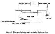
- a diagram of the working principle taken from DE 43 32 933 C 2 is shown in Figure 2.
- This type of device relies on a particular property of the additive, whose registered name is "SATAcen®", namely the ability to be pressed and sintered into fuel-soluble pellets.
- the pellets are contained in the vessel marked 1 in the diagram, with an orifice for fuel contact at the point marked 3 in the diagram.
- the pellets dissolve in proportion to the area of contact with the fuel, directed by item 4 in the diagram, to contact the container in which the additive pellets are stored.
- all the fuel in contact with the additive container will become dosed with additive, as the pellets slowly dissolve.
- Not all additives to be dosed into fuel are available in solid form, so this type of device is limited in its application.
- a carburettor for an engine powered by petrol or gasoline relies on the principle of flow through a venturi or orifice entraining flow of another fluid in order to mix the two fluids.
- the main fluid flowing through the venturi or orifice is air
- the second fluid, to be mixed with the air is the fuel, frequently termed petrol or gasoline.
- a flow eductor is an example of a device used to mix a major and a minor component where both fluids are in the liquid phase.
- the first fluid flowing past the end of the open eductor pipe creates a slight pressure reduction which induces the flow of a second liquid in proportion to the velocity of flow in the first. In this way, proportionate flow and mixing can be achieved with a simple mechanical device.
- Older gasoline powered vehicles almost universally consume all the fuel passing though the fuel metering device, ("once through"), commonly a carburettor. There is therefore no return flow of unbumt fuel to the fuel tank, unlike the case with many modem gasoline engine, and all diesel engine installations.
- the present invention alleviates the problems of the prior art.
- the present invention provides a process for dosing a fuel with a fuel additive comprising (i) passing the fuel from a fuel container through a dosing apparatus (ii) dosing the fuel with additive in an amount based on the fuel passing through the dosing apparatus and independently of the concentration of the additive in the fuel (iii) returning a portion ("the returned portion") of the fuel to the container.
- the amount of additive dosed to the fuel is determined based on the fuel passing through the dosing apparatus and independently of the concentration of the additive in the fuel. It will be appreciated that the amount of additive to be dosed is not controlled based on the concentration of the additive in the fuel. However, if dosing is reduced or prevented as a result of high concentration of additive in the fuel, in other words further dosing is inhibited due to the "saturation" of the fuel with the additive, this is not excluded from the scope of the present invention.
- the present invention provides a combustion engine and exhaust system comprising a fuel storage container configured to pass fuel in operation from the container to a combustion chamber via an additive dosing apparatus, and wherein combustion gases produced in operation pass through an exhaust system comprising a filter, wherein the dosing apparatus is configured to dose the fuel with additive in an amount based on the fuel passing through the dosing apparatus and independently of the concentration of the additive in the fuel and to return a portion ("the returned portion") of the fuel to the container.
- FIG. 3 shows the pattern of additive concentration resulting from use of the present dosing apparatus in a high return flow fuel installation.
- the initial supply of fuel after a refuelling event has low active additive content (ppm metal), but as fuel is consumed, active content increases exponentially until active content is very high just before refuelling.
- the simple dosing device will produce soot in the DPF containing several times the mean overall catalyst to soot ratio, and this increases the catalytic activity of the FBC. It is therefore more likely that a regeneration event will result in a difficult scenario, i.e. that of city operation, where it is known that low exhaust temperatures make soot bum out difficult to achieve.
- the dosing apparatus has a significant operational advantage over the more costly complex batch dosing system of the type employing an electronic management system.
- the regeneration performance of a DPF using the system of the present invention is likely to benefit from the characteristics of the dosing apparatus of the invention.
- the apparent disadvantage of variable additive concentration in the fuel as fuel tank level changes can in fact become an operating advantage, given the characteristics of soot storage in the DPF, followed by periodic combustion or regeneration, which is characteristic of the use of a fuel borne catalyst.
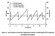
- SAE paper 982654 demonstrates the classic rise and fall of exhaust system pressure as soot first accumulates and then bums off, in DPF bed engine tests, while SAE paper 2000-01-2849 shows the same process in a test vehicle fitted with a DPF. These are shown in Figures 4 and 5 respectively.
- soot Because soot accumulates over typically 200 - 500 km of normal vehicle operation, small variations in the ratio of additive to fuel are not important, provided the overall ratio (“metal to soot ratio") of catalyst to soot is maintained. Thus, although at any time during the soot accumulation phase, the metal to soot ratio will vary within a reasonably narrow range because of variation in the proportion of return flow, over the time taken to cover 200-500 km, these variations are not important.
- the fuel pumped by the main injection pump is not a linear function of the speed of the engine, because of volumetric efficiency changes with rotational speed.
- the volume pumped per stroke at slow rotational speeds is greater than the volume pumped per stroke at high rotational speed.
- the flow of fuel at 1000 rev/min will be significantly greater than one quarter of the flow at 4000 rev/min.
- the DPF acts as an averaging device in terms of metal to soot ratio, through accumulation of pre-treated soot, it is possible to fix dosing levels of the additive at a mean value between that ideally required for maximum and for minimum fuel flows to the engine.
- the non-linearity of fuel flow already described makes this process easier, and enables the elimination of the fuel flow meter in the simple dosing device.
- the characteristics of the flow return arrangements to the tank also have the effect of encouraging a proportionately higher additive dose rate at low engine speeds than at high engine speeds, since more of the total fuel pumped by the engine injector pump returns to the tank at low engine speeds than at high engine speeds.
- the practical consequences of this are that for sustained high speed operation, additive concentration in the fuel and hence the metal to soot ratio will tend to decrease to low levels over time, whereas for sustained city operation, additive concentration in the fuel and the metal to soot ratio will tend to increase over time.
- the fuel is diesel.
- the fuel additive is or comprises a metal.
- the metal is selected from iron, strontium, calcium, cerium, sodium, platinum, copper, manganese and mixtures thereof. More preferably the metal is iron.
- the additive is added to the fuel in direct proportion to the instantaneous fuel flow through the dosing apparatus.
- the additive is added to the fuel based on the flow of fuel passing through the dosing apparatus averaged over time.
- the additive is added to the fuel based on the average flow of fuel passing through the dosing apparatus:
- the time period over which an average may be determined may be determined by one skilled in the art. Typical time periods over which averaging may be performed are 1 minute, 1 hour, 10 hours, 100 hours, 1000 hours, and 10,000 hours.
- the portion of the fuel which is not returned to the container is passed to combustion chamber. More preferably the portion of the fuel returned to the container is at least 80% of the fuel passing through the dosing apparatus.
- the additive dose rate is from 5 to 25% of the desired mean additive treat rate.
- the additive dose rate is from 10 to 15 % of the desired mean additive treat rate.
- the dosage apparatus may be situated anywhere along the path of fuel from the fuel container to its return to the container.
- the process further comprises passing at least some of the returned portion of fuel through the dosing apparatus one or more further times and returning a portion thereof to the container.
- the dosing apparatus comprises an arrangement of an additive container containing a solid fuel soluble additive, such as pellets of SATAcen® iron organo-metallic additive, with an orifice in the lower end by means of which fuel flowing in a pipeline is brought into contact with the additive.
- a solid fuel soluble additive such as pellets of SATAcen® iron organo-metallic additive
- the dosing apparatus comprises an additive container containing a liquid fuel soluble additive connected to an electro-mechanical device which meters additive and effects the addition of additive into fuel on the basis of fuel flowing through the apparatus.
- the electro-mechanical device is an electrically driven solenoid which controls the amount of additive to be mixed into the fuel and causes it to mix in the desired proportion with fuel flowing through the apparatus.
- the solenoid device is arranged to operate in a series of pulses at a frequency controlled by an electrical circuit producing a wave form or signal. In this way the flow of the additive into the fuel is controlled based on the fuel flowing through the apparatus.
- the efflux from the solenoid device is arranged to mix with the fuel fed to the engine by means of a suitable fluid communication.
- the dosing apparatus comprises liquid additive disposed in an additive container which is in fluid communication with fuel passing through the dosing apparatus.
- the liquid additive may be dosed into the fuel passing through the dosing apparatus by an electromagnetic device.
- the electromagnetic device may be controlled by an electrical circuit to dose additive at a controlled frequency.
- the electrical circuit may dose additive at a controlled frequency in proportion to the flow of fuel.
- the electrical circuit may dose additive at a controlled frequency at a fixed level independent of the flow of fuel.
- the electromagnetic device is a solenoid.
- the dosing apparatus comprises solid fuel soluble additive disposed in an additive container wherein the additive container is in fluid communication with fuel passing through the dosing apparatus.
- the fuel passing through the dosing apparatus may be controlled by an electromagnetic device.
- the electromagnetic device may be controlled by an electrical circuit to control fuel flow through the dosing apparatus.
- the electrical circuit may control the fuel flow through the dosing apparatus in proportion to the flow of fuel from the container.
- the electrical circuit may control the fuel flow through the dosing apparatus in proportion to the flow of fuel returning to the container.
- the electrical circuit may control the fuel flow through the dosing apparatus independently of the flow of fuel to or from the container.
- the electromagnetic device is a solenoid.
- the fluid communication may be achieved in a variety of ways.
- Additive leaving the electro-mechanical device can be conveyed through a rigid or flexible pipe connected between the electro-mechanical device and the fuel pipe into which the additive is to be mixed. If this method is adopted, it may be advantageous to arrange for an injector or similar device to be fitted at the point of connection of the additive feed line to the fuel line.
- the purpose of this injector or similar device is to control the efflux from the electro-mechanical device and to prevent flow of fuel into the pipe connecting the electro-mechanical device to the fuel line. In a simplification, where a very short connecting pipe is employed, the injector device may be omitted.
- the electro-mechanical device alternatively can be attached directly to the fuel pipe such that any efflux from the electro-mechanical device passes directly into the fuel.
- fuel can be arranged to flow axially past the electro-mechanical device, thereby providing cooling, and simultaneously allowing mixing of efflux from the electro-mechanical device with fuel flowing over it.
- the complete dosing system may include an additive reservoir or tank for storage of required amount additive to supply the engine with treated fuel, for example over an operational range of many thousands of kilometres, as is convenient for storage on board the vehicle.
- a connection from the additive storage vessel to the electro-mechanical device is necessary to permit this device to dispense additive into the fuel.
- the additive storage container may be arranged remotely from the dosing device using a rigid or flexible pipe connection to allow additive to flow into the dosing device.
- the additive container may be directly coupled to the dosing device using a rigid connection.
- the dosing device may be installed inside the additive container such that the efflux from the dosing device is connected to the pipe supplying fuel to the engine.
- a simple additive dosing device was used with a 1.9 litre Peugeot diesel engine, type XUD 9, mounted on a test bed.
- the exhaust system of the test engine was equipped with a diesel particulate filter (DPF) which trapped soot particles produced by the bed engine.
- the exhaust line of the bed engine was equipped with a pressure transducer and with thermocouples upstream and downstream of the DPF, in order to produce data of use in the test.
- the bed engine was arranged to drive a load absorbing device, or dynamometer, and equipped with a computer control system familiar to those involved in engine testing. As a result of this equipment, the engine could be controlled to operate at desired speed and load conditions for long periods, without the need for manual intervention.
- Fuel for the bed engine was passed in a feed line from a supply contained in a tank of 50 litres capacity.
- the fuel supply from the tank was arranged to pass through the dosing apparatus before entering the injection pump of the diesel engine.
- the dosing apparatus comprised an additive storage tank, electromechanical injector unit, an electrical pulse generator and necessary piping to connect the devices.
- the dosing apparatus treated the fuel with a fixed proportion of additive at a treat rate in the range of approximately 10% -15% of the desired mean treat rate needed for regeneration of the DPF.
- the treat rate needed for DPF regeneration lies in the range 5-30mg iron/kg of fuel, with a preferred typical treat rate of 20mg iron/kg of fuel.
- the dosing device achieved a treat rate of1.5mg iron/kg, on the basis that typically 80% - 95% of the fuel pumped by the engine injector pump returned to the tank. Most of the bed engine fuel would thus pass through the dosing device many times before finally being consumed by the bed engine. Each pass through the dosing device would increase the effective additive treat rate, thus increasing the iron content in the fuel.
- soot accumulation in a DPF results in an increase in exhaust line pressure after some hours of engine operation. This is caused by the increasing resistance to flow of exhaust gas resulting from soot accumulation in the blind channels of the DPF.
- DPF pressure builds up as indicated in Figure 4. Bum-out of the soot may occur spontaneously, following which exhaust line pressure will fall rapidly, accompanied by an exothermic reaction. This produces differences in exhaust gas temperatures, as measured by the thermocouples upstream and downstream of the DPF. Repeated soot accumulation and bum-out events produce the characteristic "saw-tooth" pattern of exhaust pressure indicated in Figure 4, which also shows the effect on exhaust gas temperatures of exothermic soot bum-out within the DPF.
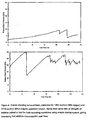
- Figure 8 shows exhaust back pressure traces for two different engine operating conditions, 1260 rev/min 5 Nm torque (upper panel) and 2710 rev/min 30 Nm torque (lower panel).
- the simple dosing device was set to provide identical fixed 34mg/h additive treat rate to the fuel by means of the frequency of operation of the solenoid operated dosing device.
- the steady increase in additive content in fuel over time resulting from recirculation to the tank of unbumt fuel and consequent multiple treatment is reflected in the more frequent regeneration of the DPF after typically 15-20h operation.
- the use of fixed additive treat rate for widely differing engine operation conditions and fuel consumption levels surprisingly results in satisfactory regeneration in the DPF at both conditions.
- Figure 9 shows calculated changes in fuel content over time for the two engine operating conditions with a fixed additive treat rate to the fuel of 34mg/h.
- the upper two panels show calculations for 1260 rev/min 5Nm engine operating conditions.
- the lower two panels show data for 2710rev/min 30Nm engine operating conditions.
- Each "saw tooth" shape represents the effect of fuel level in the tank falling to a low lever and subsequent addition of fresh fuel, otherwise described as a refuelling event Average metal concentration over time is seen to increase progressively with each refuelling event, until stabilisation takes place.
- Use of the same fixed additive treat rate of 34mg/h at constant low speed low load operation is seen to result in a stabilised average metal concentration of just over 30mg/kg.
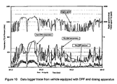
- Figure 10 shows data logger traces from a vehicle equipped with a DPF and also fitted with additive dosing apparatus operating on the principles of the present invention.
- the dosing apparatus used an electro-mechanical solenoid device to deliver an organo-metallic fuel additive into the fuel line feeding the injection pump of the vehicle.
- the additive treat rate was calculated on the basis of the possible maximum and minimum fuel flows passing through the dosing apparatus, the solenoid operation was operated at a fixed frequency independent of the actual flow of fuel.
- Figure 10 shows several similarities to Figure 5, which depicts a regeneration event in a vehicle operating on fuel pre-treated with the same DPF regeneration additive at a treat rate delivering 20ppm metal.
- Figure 10 show that when an additive dosing apparatus embodying the features of the present invention is fitted to a vehicle equipped with a DPF, regeneration is essentially very similar to that achieved with fuel pre-treated with additive.
- Figure 11 shows the additive concentration profile in the fuel as observed from fuel samples taken over a period of about 10 days.
- the samples were taken from the tank of the same road vehicle equipped with a DPF and fitted with an additive dosing apparatus embodying the features of the present invention.
- the vehicle was refuelled several times, as is evident from the changing concentration of additive in the fuel.
- fuel additive concentration in the fuel fell from a high level when the tank was nearly empty to a very low level immediately after refuelling. This is consistent with the anticipated and calculated pattern of additive concentration in the fuel, when a dosing apparatus embodying the features of the present invention is employed.
Landscapes
- Chemical & Material Sciences (AREA)
- Engineering & Computer Science (AREA)
- Oil, Petroleum & Natural Gas (AREA)
- Combustion & Propulsion (AREA)
- Organic Chemistry (AREA)
- General Engineering & Computer Science (AREA)
- General Chemical & Material Sciences (AREA)
- Mechanical Engineering (AREA)
- Chemical Kinetics & Catalysis (AREA)
- Inorganic Chemistry (AREA)
- Processes For Solid Components From Exhaust (AREA)
- Loading And Unloading Of Fuel Tanks Or Ships (AREA)
- Exhaust Gas After Treatment (AREA)
- Solid Fuels And Fuel-Associated Substances (AREA)
- Output Control And Ontrol Of Special Type Engine (AREA)
- Liquid Carbonaceous Fuels (AREA)
- Feeding And Controlling Fuel (AREA)
Abstract
Description
Claims (26)
- A process for dosing a fuel with a fuel additive comprising(i) passing the fuel from a fuel container through a dosing apparatus(ii) dosing the fuel with additive in an amount based on the fuel passing through the dosing apparatus and independently of the concentration of the additive in the fuel(iii) returning a portion ("the returned portion") of the fuel to the container
- A process according to claim 1 wherein the additive is added to the fuel in direct proportion to the instantaneous fuel flow through the dosing apparatus.
- A process according to claim 1 wherein the additive is added to the fuel based on the flow of fuel passing through the dosing apparatus averaged over time.
- A process according to claim 1, 2 or 3 wherein the fuel is diesel.
- A process according to any one of claims 1 to 4 wherein the fuel additive is capable of catalysing the regeneration of a diesel particulate filter.
- A process according to claim 5 wherein the fuel additive is or comprises a metal.
- A process according to claim 6 wherein the metal is selected from iron, strontium, calcium, cerium, sodium, platinum, copper, manganese and mixtures thereof.
- A process according to claim 7 wherein the metal is iron.
- A process according to any of claims 5 to 8 wherein the fuel additive is soluble in the fuel.
- A process according to any preceding claim wherein the portion of the fuel which is not returned to the container is passed to combustion chamber.
- A process according to any preceding claim wherein the portion of the fuel returned to the container is at least 80% of the fuel passing through the dosing apparatus.
- A process according to any preceding claim further comprising passing at least some of the returned portion through the dosing apparatus one or more further times and returning a portion thereof to the container.
- A process according to any preceding claim wherein the dosing apparatus comprises solid fuel soluble additive disposed in an additive container wherein the additive container is in fluid communication with fuel passing through the dosing apparatus.
- A process according to claim 13 wherein the fuel passing through the dosing apparatus is controlled by an electromagnetic device.
- A process according to claim 14 wherein the electromagnetic device is controlled by an electrical circuit to control fuel flow through the dosing apparatus.
- A process according to claim 14 or 15 wherein the electrical circuit controls the fuel flow through the dosing apparatus in proportion to the flow of fuel from the container.
- A process according to claim 14 or 15 wherein the electrical circuit controls the fuel flow through the dosing apparatus in proportion to the flow of fuel returning to the container.
- A process according to claim 14 or 15 wherein the electrical circuit controls the fuel flow through the dosing apparatus independently of the flow of fuel to or from the container.
- A process according to any one of claims 14 to 18 wherein the electromagnetic device is a solenoid.
- A process according to any one of claims 1 to 12 wherein the dosing apparatus comprises liquid additive disposed in an additive container which is in fluid communication with fuel passing through the dosing apparatus.
- A process according to claim 20 wherein the liquid additive is dosed into the fuel passing through the dosing apparatus by an electromagnetic device.
- A process according to claim 21 wherein the electromagnetic device is controlled by an electrical circuit to dose additive at a controlled frequency.
- A process according to claim 22 wherein the electrical circuit doses additive at a controlled frequency in proportion to the flow of fuel.
- A process according to claim 22 wherein the electrical circuit doses additive at a controlled frequency at a fixed level independent of the instantaneous flow of fuel.
- A process according to any one of claims 21 to 24 wherein the electromagnetic device is a solenoid.
- A combustion engine and exhaust system comprising
a fuel storage container configured to pass fuel in operation from the container to a combustion chamber via an additive dosing apparatus, and wherein combustion gases produced in operation pass through an exhaust system comprising a filter,
wherein the dosing apparatus is configured to dose the fuel with additive in an amount based on the fuel passing through the dosing apparatus and independently of the concentration of the additive in the fuel and to return a portion ("the returned portion") of the fuel to the container.
Applications Claiming Priority (5)
| Application Number | Priority Date | Filing Date | Title |
|---|---|---|---|
| GB0113195A GB0113195D0 (en) | 2001-05-31 | 2001-05-31 | Process |
| GB0113195 | 2001-05-31 | ||
| GB0204506A GB0204506D0 (en) | 2002-02-26 | 2002-02-26 | Process |
| GB0204506 | 2002-02-26 | ||
| PCT/GB2002/001802 WO2002097256A2 (en) | 2001-05-31 | 2002-04-18 | Process for dosing an additive into a fuel |
Publications (2)
| Publication Number | Publication Date |
|---|---|
| EP1392960A2 EP1392960A2 (en) | 2004-03-03 |
| EP1392960B1 true EP1392960B1 (en) | 2005-03-23 |
Family
ID=26246136
Family Applications (1)
| Application Number | Title | Priority Date | Filing Date |
|---|---|---|---|
| EP02718362A Revoked EP1392960B1 (en) | 2001-05-31 | 2002-04-18 | Process for dosing an additive into a fuel |
Country Status (13)
| Country | Link |
|---|---|
| US (1) | US7134405B2 (en) |
| EP (1) | EP1392960B1 (en) |
| JP (1) | JP2004526902A (en) |
| CN (1) | CN100376781C (en) |
| AT (1) | ATE291691T1 (en) |
| AU (1) | AU2002249432B2 (en) |
| BR (1) | BR0209779A (en) |
| CA (1) | CA2448177C (en) |
| DE (1) | DE60203389T2 (en) |
| ES (1) | ES2238564T3 (en) |
| MX (1) | MXPA03011059A (en) |
| TW (1) | TW593876B (en) |
| WO (1) | WO2002097256A2 (en) |
Families Citing this family (14)
| Publication number | Priority date | Publication date | Assignee | Title |
|---|---|---|---|---|
| CN101120163B (en) * | 2004-12-23 | 2011-02-09 | 克林迪塞尔技术公司 | Engine-on pulsed fuel additive concentrate dosing system and controller |
| US20060254536A1 (en) * | 2005-03-09 | 2006-11-16 | Waters Paul F | Engine control module linked additive injection system |
| FR2887302A1 (en) * | 2005-06-21 | 2006-12-22 | Peugeot Citroen Automobiles Sa | Additive forming unit introducing device for motor vehicle fuel tank, has control case associated to units analyzing moving conditions of vehicle to control pump and injector to adapt additive concentration in fuel to conditions |
| FR2897394B1 (en) * | 2006-02-10 | 2008-05-16 | Peugeot Citroen Automobiles Sa | DEVICE FOR AUTOMATICALLY INTRODUCING MEANS FORMING ADDITIVE IN THE FUEL DELIVERY CIRCUIT OF A MOTOR VEHICLE |
| US7856808B2 (en) * | 2007-06-25 | 2010-12-28 | Detroit Diesel Corporation | Method to re-open ash filled channels in diesel particulate filters |
| WO2009059102A2 (en) * | 2007-11-01 | 2009-05-07 | Parker Hannifin Corporation | Diesel engine |
| GB0811144D0 (en) * | 2008-06-18 | 2008-07-23 | Parker Hannifin U K Ltd | A liquid drain system |
| US9194272B2 (en) * | 2008-12-02 | 2015-11-24 | Caterpillar Inc. | Power system |
| FR2972766B1 (en) * | 2011-03-17 | 2015-08-07 | Rhodia Operations | METHOD FOR OPERATING A FUEL-FEED ENGINE CONTAINING A CATALYST FOR REGENERATING A PARTICLE FILTER |
| JP6203727B2 (en) | 2011-09-07 | 2017-09-27 | アフトン・ケミカル・コーポレーションAfton Chemical Corporation | Pneumatic transport engine additive delivery system |
| US20140294606A1 (en) * | 2013-03-28 | 2014-10-02 | Liquid Automation LLC | Automatic Fuel Additive Controller and Dispenser |
| FR3055220B1 (en) * | 2016-08-26 | 2020-02-28 | IFP Energies Nouvelles | INSTALLATION FOR THE DEPOLLUTION OF EXHAUST GASES, ESPECIALLY AN INTERNAL COMBUSTION ENGINE, AND METHOD FOR THE USE OF SUCH AN INSTALLATION |
| WO2022203755A1 (en) * | 2021-03-25 | 2022-09-29 | Real Time Automated Technologies Llc | Methods and systems for real-time dosing of additives into a fuel supply unit |
| US11313292B1 (en) * | 2021-03-25 | 2022-04-26 | Real Time Automated Technologies Llc | Methods and systems for real-time dosing of additives into a fuel supply unit |
Family Cites Families (21)
| Publication number | Priority date | Publication date | Assignee | Title |
|---|---|---|---|---|
| US4161160A (en) | 1977-10-31 | 1979-07-17 | Caterpillar Tractor Co. | Fuel additive injection system for diesel engines |
| US4557221A (en) * | 1983-05-27 | 1985-12-10 | Cummins Engine Company, Inc. | Fuel additive injection system |
| JPS6082517A (en) | 1983-10-14 | 1985-05-10 | Toshiba Corp | Control method for operation of conveyor |
| DE3337983C2 (en) * | 1983-10-19 | 1986-09-04 | TUNAP Industrie Chemie GmbH & Co KG, 8190 Wolfratshausen | Method and device for the continuous supply of internal combustion engines and / or auxiliary devices thereof with additives |
| JPS60108710A (en) | 1983-11-18 | 1985-06-14 | Komatsu Ltd | Incremental encoder abnormality detection device |
| US4568248A (en) | 1984-04-26 | 1986-02-04 | Harders Mark R | Additive feedback monitoring system |
| JPS6174615A (en) | 1984-09-20 | 1986-04-16 | Kawasaki Steel Corp | Method for controlling amount of air to be sucked in collecting dust by plural dust collecting system |
| US4621593A (en) * | 1984-12-24 | 1986-11-11 | Ford Motor Company | Automotive dispensing apparatus for fuel additive |
| US4715325A (en) * | 1986-06-19 | 1987-12-29 | Walker Claud W | Pollution control through fuel treatment |
| DE3626419A1 (en) | 1986-08-05 | 1988-02-18 | Bayerische Motoren Werke Ag | Fuel additive feed device |
| US4727827A (en) * | 1986-11-25 | 1988-03-01 | General Motors Corporation | Fuel additive metering system |
| FR2669967B1 (en) | 1990-11-30 | 1993-03-19 | Peugeot | METHOD AND DEVICE FOR INTRODUCING A QUANTITY ADDED INTO THE INJECTION CIRCUIT OF A COMPRESSION IGNITION ENGINE. |
| DE4106697C1 (en) | 1991-03-02 | 1992-04-09 | Mercedes-Benz Aktiengesellschaft, 7000 Stuttgart, De | Fuel additive dosing device - is used in vehicle and incorporates cylinder divided into two working chambers by piston |
| DE4117148C1 (en) * | 1991-05-25 | 1992-07-23 | Mercedes-Benz Aktiengesellschaft, 7000 Stuttgart, De | |
| WO1995003482A1 (en) | 1993-07-21 | 1995-02-02 | Timber Traders Pty. Limited | Dosing system |
| DE4332933C2 (en) | 1993-09-28 | 1995-10-12 | Pluto Chem Betriebe | Device for the additivation of liquid fuels |
| FR2714694B1 (en) | 1993-12-30 | 1996-03-15 | Peugeot | Method and device for variable dosing of regeneration additive for particulate filters. |
| DE19805311B4 (en) * | 1997-02-18 | 2010-06-10 | Walbro Corp., Cass City | Apparatus and method for adding fuel additives |
| KR100653817B1 (en) * | 1998-01-15 | 2006-12-05 | 이노스펙 리미티드 | Fuel additives |
| US6276310B1 (en) | 2000-01-07 | 2001-08-21 | Ford Global Technologies, Inc. | Fuel additive dosing method and system for onboard vehicle use |
| FR2809450B1 (en) | 2000-05-26 | 2002-07-26 | Renault | FUEL ADDITIVATION PROCESS |
-
2002
- 2002-04-18 CA CA 2448177 patent/CA2448177C/en not_active Expired - Fee Related
- 2002-04-18 ES ES02718362T patent/ES2238564T3/en not_active Expired - Lifetime
- 2002-04-18 MX MXPA03011059A patent/MXPA03011059A/en active IP Right Grant
- 2002-04-18 US US10/479,313 patent/US7134405B2/en not_active Expired - Fee Related
- 2002-04-18 BR BR0209779A patent/BR0209779A/en not_active Application Discontinuation
- 2002-04-18 AU AU2002249432A patent/AU2002249432B2/en not_active Ceased
- 2002-04-18 DE DE2002603389 patent/DE60203389T2/en not_active Revoked
- 2002-04-18 WO PCT/GB2002/001802 patent/WO2002097256A2/en not_active Ceased
- 2002-04-18 AT AT02718362T patent/ATE291691T1/en not_active IP Right Cessation
- 2002-04-18 JP JP2003500403A patent/JP2004526902A/en active Pending
- 2002-04-18 EP EP02718362A patent/EP1392960B1/en not_active Revoked
- 2002-04-18 CN CNB028108930A patent/CN100376781C/en not_active Expired - Fee Related
- 2002-04-25 TW TW91108560A patent/TW593876B/en not_active IP Right Cessation
Also Published As
| Publication number | Publication date |
|---|---|
| CA2448177A1 (en) | 2002-12-05 |
| CN1533473A (en) | 2004-09-29 |
| BR0209779A (en) | 2004-06-01 |
| EP1392960A2 (en) | 2004-03-03 |
| MXPA03011059A (en) | 2004-03-19 |
| AU2002249432B2 (en) | 2006-06-08 |
| US20040231615A1 (en) | 2004-11-25 |
| CA2448177C (en) | 2006-01-03 |
| CN100376781C (en) | 2008-03-26 |
| WO2002097256A3 (en) | 2003-03-13 |
| DE60203389D1 (en) | 2005-04-28 |
| WO2002097256A2 (en) | 2002-12-05 |
| DE60203389T2 (en) | 2005-09-15 |
| ES2238564T3 (en) | 2005-09-01 |
| ATE291691T1 (en) | 2005-04-15 |
| US7134405B2 (en) | 2006-11-14 |
| TW593876B (en) | 2004-06-21 |
| JP2004526902A (en) | 2004-09-02 |
Similar Documents
| Publication | Publication Date | Title |
|---|---|---|
| CA2448177C (en) | Process for dosing an additive into a fuel | |
| AU2002249432A1 (en) | Process for dosing an additive into a fuel | |
| CN103890368B (en) | A kind of dispensing device for being dispensed in the fuel recirculation loop of explosive motor by liquid additive, include the vehicle of this equipment and the method being used for using described equipment | |
| US4892562A (en) | Diesel fuel additives and diesel fuels containing soluble platinum group metal compounds and use in diesel engines | |
| CN101219339B (en) | Method and apparatus for selectively reducing NOx in an exhaust gas feedstream | |
| Salvat et al. | Passenger car serial application of a particulate filter system on a common rail direct injection diesel engine | |
| US5758496A (en) | Particulate and exhaust gas emission control system | |
| US5651247A (en) | Exhaust gas purification system | |
| US20090205316A1 (en) | System and processes for storing an additive and injecting it into the exhaust gases of an engine | |
| US20060037309A1 (en) | Emission control system | |
| CN103534471A (en) | Device for dispensing an additive | |
| CN104093963B (en) | The method for diagnosing the failure of the equipment for additive to be added in motor vehicle fuel, and implement the system of methods described | |
| Campenon et al. | Improvement and simplification of DPF system using a ceria-based fuel-borne catalyst for diesel particulate filter regeneration in serial applications | |
| AU583580B2 (en) | Fuel additives and fuel containing soluble platinum group metal compounds | |
| ZA200309123B (en) | Process for dosing an additive into a fuel. | |
| RU2573547C2 (en) | System for postprocessing of used gases with addition of activating material to be added to catalytic neutraliser | |
| JP2016200149A (en) | Method for operating an engine supplied with fuel containing a catalyst for regenerating a particulate filter | |
| Quigley et al. | Series application of a diesel particulate filter with a ceria-based fuel-borne catalyst: preliminary conclusions after one year of service | |
| EP0189642B1 (en) | Fuel additives and fuel containing soluble platinum group metal compounds and use in internal combustion engines | |
| Vincent et al. | A novel fuel borne catalyst dosing system for use with a diesel particulate filter | |
| Yang et al. | Study on a versatile liquid dosing device for IC engine after-treatment system | |
| Starkman | Vehicular emissions and control |
Legal Events
| Date | Code | Title | Description |
|---|---|---|---|
| PUAI | Public reference made under article 153(3) epc to a published international application that has entered the european phase |
Free format text: ORIGINAL CODE: 0009012 |
|
| 17P | Request for examination filed |
Effective date: 20031217 |
|
| AK | Designated contracting states |
Kind code of ref document: A2 Designated state(s): AT BE CH CY DE DK ES FI FR GB GR IE IT LI LU MC NL PT SE TR |
|
| AX | Request for extension of the european patent |
Extension state: AL LT LV MK RO SI |
|
| GRAP | Despatch of communication of intention to grant a patent |
Free format text: ORIGINAL CODE: EPIDOSNIGR1 |
|
| 17Q | First examination report despatched |
Effective date: 20040802 |
|
| GRAS | Grant fee paid |
Free format text: ORIGINAL CODE: EPIDOSNIGR3 |
|
| GRAA | (expected) grant |
Free format text: ORIGINAL CODE: 0009210 |
|
| AK | Designated contracting states |
Kind code of ref document: B1 Designated state(s): AT BE CH CY DE DK ES FI FR GB GR IE IT LI LU MC NL PT SE TR |
|
| PG25 | Lapsed in a contracting state [announced via postgrant information from national office to epo] |
Ref country code: FI Free format text: LAPSE BECAUSE OF FAILURE TO SUBMIT A TRANSLATION OF THE DESCRIPTION OR TO PAY THE FEE WITHIN THE PRESCRIBED TIME-LIMIT Effective date: 20050323 |
|
| REG | Reference to a national code |
Ref country code: GB Ref legal event code: FG4D |
|
| REG | Reference to a national code |
Ref country code: CH Ref legal event code: EP |
|
| PG25 | Lapsed in a contracting state [announced via postgrant information from national office to epo] |
Ref country code: CY Free format text: LAPSE BECAUSE OF FAILURE TO SUBMIT A TRANSLATION OF THE DESCRIPTION OR TO PAY THE FEE WITHIN THE PRESCRIBED TIME-LIMIT Effective date: 20050418 |
|
| REG | Reference to a national code |
Ref country code: IE Ref legal event code: FG4D |
|
| REF | Corresponds to: |
Ref document number: 60203389 Country of ref document: DE Date of ref document: 20050428 Kind code of ref document: P |
|
| PG25 | Lapsed in a contracting state [announced via postgrant information from national office to epo] |
Ref country code: MC Free format text: LAPSE BECAUSE OF NON-PAYMENT OF DUE FEES Effective date: 20050430 |
|
| REG | Reference to a national code |
Ref country code: CH Ref legal event code: NV Representative=s name: MICHELI & CIE INGENIEURS-CONSEILS |
|
| REG | Reference to a national code |
Ref country code: DK Ref legal event code: T3 |
|
| PG25 | Lapsed in a contracting state [announced via postgrant information from national office to epo] |
Ref country code: GR Free format text: LAPSE BECAUSE OF FAILURE TO SUBMIT A TRANSLATION OF THE DESCRIPTION OR TO PAY THE FEE WITHIN THE PRESCRIBED TIME-LIMIT Effective date: 20050623 |
|
| REG | Reference to a national code |
Ref country code: SE Ref legal event code: TRGR |
|
| REG | Reference to a national code |
Ref country code: ES Ref legal event code: FG2A Ref document number: 2238564 Country of ref document: ES Kind code of ref document: T3 |
|
| PG25 | Lapsed in a contracting state [announced via postgrant information from national office to epo] |
Ref country code: PT Free format text: LAPSE BECAUSE OF FAILURE TO SUBMIT A TRANSLATION OF THE DESCRIPTION OR TO PAY THE FEE WITHIN THE PRESCRIBED TIME-LIMIT Effective date: 20050907 |
|
| REG | Reference to a national code |
Ref country code: GB Ref legal event code: 732E |
|
| PLBI | Opposition filed |
Free format text: ORIGINAL CODE: 0009260 |
|
| PLAX | Notice of opposition and request to file observation + time limit sent |
Free format text: ORIGINAL CODE: EPIDOSNOBS2 |
|
| 26 | Opposition filed |
Opponent name: INFINEUM INTERNATIONAL LTD.,IP LAW DEPT. Effective date: 20051222 |
|
| ET | Fr: translation filed | ||
| NLR1 | Nl: opposition has been filed with the epo |
Opponent name: INFINEUM INTERNATIONAL LTD.,IP LAW DEPT. |
|
| PLAF | Information modified related to communication of a notice of opposition and request to file observations + time limit |
Free format text: ORIGINAL CODE: EPIDOSCOBS2 |
|
| RAP2 | Party data changed (patent owner data changed or rights of a patent transferred) |
Owner name: INNOSPEC LIMITED |
|
| PLAF | Information modified related to communication of a notice of opposition and request to file observations + time limit |
Free format text: ORIGINAL CODE: EPIDOSCOBS2 |
|
| REG | Reference to a national code |
Ref country code: CH Ref legal event code: PFA Owner name: INNOSPEC LIMITED Free format text: THE ASSOCIATED OCTEL COMPANY LIMITED#GLOBAL HOUSE, BAILEY LANE#MANCHESTER M90 4AA (GB) -TRANSFER TO- INNOSPEC LIMITED#INNOSPEC MANUFACTURING PARK OIL SITES ROAD#ELLESMERE PORT, CHESHIRE CH65 4EY (GB) |
|
| NLT2 | Nl: modifications (of names), taken from the european patent patent bulletin |
Owner name: INNOSPEC LIMITED Effective date: 20060823 |
|
| PLBB | Reply of patent proprietor to notice(s) of opposition received |
Free format text: ORIGINAL CODE: EPIDOSNOBS3 |
|
| NLT1 | Nl: modifications of names registered in virtue of documents presented to the patent office pursuant to art. 16 a, paragraph 1 |
Owner name: INNOSPEC LIMITED |
|
| REG | Reference to a national code |
Ref country code: FR Ref legal event code: CD |
|
| BECA | Be: change of holder's address |
Owner name: *INNOSPEC LTDINNOSPEC MANUFACTURING PARK, OIL SITE Effective date: 20050323 |
|
| BECN | Be: change of holder's name |
Owner name: *INNOSPEC LTD Effective date: 20050323 |
|
| REG | Reference to a national code |
Ref country code: ES Ref legal event code: PC2A |
|
| APBM | Appeal reference recorded |
Free format text: ORIGINAL CODE: EPIDOSNREFNO |
|
| APBP | Date of receipt of notice of appeal recorded |
Free format text: ORIGINAL CODE: EPIDOSNNOA2O |
|
| APAH | Appeal reference modified |
Free format text: ORIGINAL CODE: EPIDOSCREFNO |
|
| APAW | Appeal reference deleted |
Free format text: ORIGINAL CODE: EPIDOSDREFNO |
|
| APBQ | Date of receipt of statement of grounds of appeal recorded |
Free format text: ORIGINAL CODE: EPIDOSNNOA3O |
|
| APBQ | Date of receipt of statement of grounds of appeal recorded |
Free format text: ORIGINAL CODE: EPIDOSNNOA3O |
|
| PLAB | Opposition data, opponent's data or that of the opponent's representative modified |
Free format text: ORIGINAL CODE: 0009299OPPO |
|
| PGFP | Annual fee paid to national office [announced via postgrant information from national office to epo] |
Ref country code: LU Payment date: 20100427 Year of fee payment: 9 |
|
| PGFP | Annual fee paid to national office [announced via postgrant information from national office to epo] |
Ref country code: GB Payment date: 20100215 Year of fee payment: 9 Ref country code: TR Payment date: 20100325 Year of fee payment: 9 |
|
| PGFP | Annual fee paid to national office [announced via postgrant information from national office to epo] |
Ref country code: DK Payment date: 20100413 Year of fee payment: 9 Ref country code: ES Payment date: 20100427 Year of fee payment: 9 Ref country code: FR Payment date: 20100506 Year of fee payment: 9 Ref country code: IE Payment date: 20100422 Year of fee payment: 9 |
|
| PGFP | Annual fee paid to national office [announced via postgrant information from national office to epo] |
Ref country code: AT Payment date: 20100415 Year of fee payment: 9 Ref country code: DE Payment date: 20100423 Year of fee payment: 9 Ref country code: IT Payment date: 20100427 Year of fee payment: 9 Ref country code: NL Payment date: 20100413 Year of fee payment: 9 |
|
| APBU | Appeal procedure closed |
Free format text: ORIGINAL CODE: EPIDOSNNOA9O |
|
| PGFP | Annual fee paid to national office [announced via postgrant information from national office to epo] |
Ref country code: BE Payment date: 20100419 Year of fee payment: 9 Ref country code: CH Payment date: 20100423 Year of fee payment: 9 |
|
| PGFP | Annual fee paid to national office [announced via postgrant information from national office to epo] |
Ref country code: SE Payment date: 20100415 Year of fee payment: 9 |
|
| RDAF | Communication despatched that patent is revoked |
Free format text: ORIGINAL CODE: EPIDOSNREV1 |
|
| RDAG | Patent revoked |
Free format text: ORIGINAL CODE: 0009271 |
|
| STAA | Information on the status of an ep patent application or granted ep patent |
Free format text: STATUS: PATENT REVOKED |
|
| REG | Reference to a national code |
Ref country code: CH Ref legal event code: PL |
|
| 27W | Patent revoked |
Effective date: 20100720 |
|
| GBPR | Gb: patent revoked under art. 102 of the ep convention designating the uk as contracting state |
Effective date: 20100720 |
|
| PG25 | Lapsed in a contracting state [announced via postgrant information from national office to epo] |
Ref country code: CH Free format text: LAPSE BECAUSE OF THE APPLICANT RENOUNCES Effective date: 20050323 Ref country code: LI Free format text: LAPSE BECAUSE OF THE APPLICANT RENOUNCES Effective date: 20050323 |
|
| REG | Reference to a national code |
Ref country code: SE Ref legal event code: ECNC |