EP1392038A1 - Portable terminal device with camera - Google Patents
Portable terminal device with camera Download PDFInfo
- Publication number
- EP1392038A1 EP1392038A1 EP02717179A EP02717179A EP1392038A1 EP 1392038 A1 EP1392038 A1 EP 1392038A1 EP 02717179 A EP02717179 A EP 02717179A EP 02717179 A EP02717179 A EP 02717179A EP 1392038 A1 EP1392038 A1 EP 1392038A1
- Authority
- EP
- European Patent Office
- Prior art keywords
- camera
- hinge
- upper case
- photographing
- terminal device
- Prior art date
- Legal status (The legal status is an assumption and is not a legal conclusion. Google has not performed a legal analysis and makes no representation as to the accuracy of the status listed.)
- Granted
Links
Images


Classifications
-
- H—ELECTRICITY
- H04—ELECTRIC COMMUNICATION TECHNIQUE
- H04M—TELEPHONIC COMMUNICATION
- H04M1/00—Substation equipment, e.g. for use by subscribers
- H04M1/02—Constructional features of telephone sets
- H04M1/0202—Portable telephone sets, e.g. cordless phones, mobile phones or bar type handsets
- H04M1/0206—Portable telephones comprising a plurality of mechanically joined movable body parts, e.g. hinged housings
- H04M1/0208—Portable telephones comprising a plurality of mechanically joined movable body parts, e.g. hinged housings characterized by the relative motions of the body parts
- H04M1/0214—Foldable telephones, i.e. with body parts pivoting to an open position around an axis parallel to the plane they define in closed position
- H04M1/0216—Foldable in one direction, i.e. using a one degree of freedom hinge
- H04M1/0218—The hinge comprising input and/or output user interface means
-
- H—ELECTRICITY
- H04—ELECTRIC COMMUNICATION TECHNIQUE
- H04N—PICTORIAL COMMUNICATION, e.g. TELEVISION
- H04N23/00—Cameras or camera modules comprising electronic image sensors; Control thereof
- H04N23/50—Constructional details
-
- H—ELECTRICITY
- H04—ELECTRIC COMMUNICATION TECHNIQUE
- H04N—PICTORIAL COMMUNICATION, e.g. TELEVISION
- H04N23/00—Cameras or camera modules comprising electronic image sensors; Control thereof
- H04N23/50—Constructional details
- H04N23/51—Housings
-
- H—ELECTRICITY
- H04—ELECTRIC COMMUNICATION TECHNIQUE
- H04N—PICTORIAL COMMUNICATION, e.g. TELEVISION
- H04N23/00—Cameras or camera modules comprising electronic image sensors; Control thereof
- H04N23/50—Constructional details
- H04N23/54—Mounting of pick-up tubes, electronic image sensors, deviation or focusing coils
-
- E—FIXED CONSTRUCTIONS
- E05—LOCKS; KEYS; WINDOW OR DOOR FITTINGS; SAFES
- E05D—HINGES OR SUSPENSION DEVICES FOR DOORS, WINDOWS OR WINGS
- E05D11/00—Additional features or accessories of hinges
-
- E—FIXED CONSTRUCTIONS
- E05—LOCKS; KEYS; WINDOW OR DOOR FITTINGS; SAFES
- E05D—HINGES OR SUSPENSION DEVICES FOR DOORS, WINDOWS OR WINGS
- E05D11/00—Additional features or accessories of hinges
- E05D11/08—Friction devices between relatively-movable hinge parts
-
- E—FIXED CONSTRUCTIONS
- E05—LOCKS; KEYS; WINDOW OR DOOR FITTINGS; SAFES
- E05Y—INDEXING SCHEME ASSOCIATED WITH SUBCLASSES E05D AND E05F, RELATING TO CONSTRUCTION ELEMENTS, ELECTRIC CONTROL, POWER SUPPLY, POWER SIGNAL OR TRANSMISSION, USER INTERFACES, MOUNTING OR COUPLING, DETAILS, ACCESSORIES, AUXILIARY OPERATIONS NOT OTHERWISE PROVIDED FOR, APPLICATION THEREOF
- E05Y2999/00—Subject-matter not otherwise provided for in this subclass
-
- H—ELECTRICITY
- H04—ELECTRIC COMMUNICATION TECHNIQUE
- H04N—PICTORIAL COMMUNICATION, e.g. TELEVISION
- H04N7/00—Television systems
- H04N7/14—Systems for two-way working
- H04N7/141—Systems for two-way working between two video terminals, e.g. videophone
- H04N7/142—Constructional details of the terminal equipment, e.g. arrangements of the camera and the display
- H04N2007/145—Handheld terminals
Definitions
- This invention relates to a mobile terminal device with a camera which can be applied as a mobile phone set provided with a camera or a mobile television phone set.
- the mobile phone set has become widely used not only as a terminal set for simple vocal communication but also as a terminal set for data communication, with a remarkable rise of its data transmitting ability.
- this data communication terminal set there has been proposed and developed a mobile phone set having such a structure that a camera is installed on the mobile phone set and an image data photographed by this camera can be transmitted and received in real time.
- this data communication terminal set because various components such as a display, operating buttons, a microphone, a speaker, an antenna and so on, for example, must be efficiently contained in a limited narrow space, a place for installing the camera is restricted similarly.
- a data communication terminal set with a camera which is so constructed that there is provided a cut-out part in a rectangular shape on a side face or a top face of the data communication terminal set, and a camera body is rotatably installed in this cut-out part.
- a data communication terminal set with a camera it is possible to adjust the camera body so as to be directed in a desired direction and also so as to be directed to an operator himself, by installing the camera body in a rotatable manner.
- the camera body is mounted to a hinge part for connecting an upper case to a lower case.
- the data communication terminal set with the camera having such an arrangement, in case of adjusting direction for photographing with this camera, for example, by directly grasping the camera body with fingers, it has been difficult to perform fine adjustments of orientation of the camera, because the camera must be operated in a narrow space between the upper and the lower cases, and moreover, the camera body is relatively small. Further, in the case where the camera is directed to an exterior of the case for photographing, operation will become more difficult because the camera is not faced with the operator.
- a data communication terminal set with a camera after photographing with a lens of the camera directed outward, the lens of the camera may sometimes be forgotten to be returned inside.
- the data communication terminal set may sometimes be carried while a cover glass and so on of the camera are kept exposed to the exterior, and there will be such a risk that the cover glass may get dirty or broken.
- the photographing action of the camera may not be stopped carelessly, and the camera keeps on photographing. As the results, it is concerned that even private scenes may be transmitted to and seen by other people unnecessarily.
- this invention provides a mobile terminal device with a camera comprising a lower case provided with an operating part, an upper case provided with a display part, a hinge part for connecting the upper case with the lower case in a foldable manner, and a photographing part installed in the hinge part, characterized in that there is provided an association mechanism by which the photographing part is rotated in association with opening and closing motions of the upper case so that the photographing part may be exposed to the exterior or retracted into the cases.
- the orientation of the camera can be easily adjusted in association with the opening and closing motions of the upper case, and the camera can be protected from the exterior in association with the motion for folding the cases of the mobile terminal device after the photographing operation has been finished.
- the hinge part includes an upper hinge which is integral with the upper case and a lower hinge which is integral with the lower case
- the association mechanism includes a first friction member provided between the upper hinge and the photographing part, wherein the first friction member has preferably friction coefficient which is larger than friction coefficient between the lower hinge and the photographing part.
- the association mechanism includes a second friction member provided between the first friction member, the lower hinge and the photographing part, and the friction coefficient of the first friction member is preferably larger than friction coefficient of the second friction member.
- the first friction member may be a C-ring or an E-ring.
- the association mechanism can be composed of simple components.
- the C-ring or E-ring may be provided with bulging portions on its circumferential edge which are adapted to come into a point contact with the upper hinge.
- the upper hinge and the lower hinge are preferably provided with restricting members for restricting rotation range of the photographing part
- the photographing part is preferably provided with a member to be restricted by the restricting members so that the rotation range of the photographing part may be restricted.
- a housing of the photographing part is formed by joining an upper housing and a lower housing, and a flexible circuit board for electrical connection between an interior of the photographing part and the upper or lower case may be drawn out through a joint portion between the upper and lower housings. According to this aspect, it will be possible to electrically connect the photographing part with other parts through the use of a slight gap.
- 1 is a lower case, 1A is an inner casing, 1B is an outer casing, 1C is an interior frame, 2 is an upper case, 2A is an inner casing, 2B is an outer casing, 2C is an interior frame, 3 is a hinge part, 4 is a lower hinge, 41 is a first rotary part (on the lower case side), 42 is a second rotary part (on the lower case side), 5 is an upper hinge, 51 is a first rotary part (on the upper case side), 52 is a second rotary part (on the upper case side), 53 is a socket portion (on the upper case side), 53A is a groove, 53B is a stopper, 6 is a photographing part, 61 is a lens barrel, 62 is a holder, 62C is a tubular portion, 62D is a groove, 63 is a cap, 63A is an open window, 64 is a lens cover, 66 is a printed circuit board,
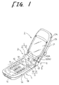
- Fig. 1 shows a mobile phone set to which a mobile terminal device with a camera according to an embodiment of the present invention is applied, and this mobile phone set has a lower case 1, an upper case 2, a hinge part 3, and besides, a photographing part 6, and an association mechanism 7.
- the lower case 1 has a structure composed of an inner casing 1A, an outer casing 1B, and an interior frame 1C (Refer to Fig. 2) which is formed of appropriate material such as magnesium.
- This lower case 1 is provided with an operating part having a plurality of buttons 11 including ten keypads, a cursor button 12, function buttons 13 such as a power button, a start button, a phone directory button, a clear button, etc., and a voice manner button 14, and a printed circuit board which is not shown in the drawings.
- a microphone which is not shown is provided adjacent to an end edge of the lower case 1.
- the upper case 2 has a structure composed of an inner casing 2A, an outer casing 2B, and an interior frame 2C (Refer to Fig. 2) which is formed of appropriate material such as magnesium and screwed into the inner casing 2A.
- This upper case 2 is provided with a display part 21 composed of a liquid crystal display part on which a picture photographed by the camera in the photographing part 6 which will be described below can be shown, and a printed circuit board 66 (Refer to Fig. 2).
- a speaker which is not shown in the drawings is provided adjacent to an end edge of the upper case 2.
- Various operating buttons may be provided on this upper case 2, though they are not provided in this embodiment.
- the hinge part 3 is intended to connect the upper case 2 to the lower case 1 so as to be folded thereon, and includes, as a general structure, a lower hinge 4 which is integral with the lower case 1 and an upper hinge 5 which is integral with the upper case 2.
- the lower hinge 4 includes a first rotary member 41 in a semi-cylindrical (a long semi-cylinder) shape which is integrally projected from the above described inner casing 1A, a second rotary part 42 in a cylindrical (a short cylinder) shape, and a socket portion in a semi-cylindrical shape which is extended from the interior frame 1C and fitted to an inner peripheral face of the first rotary member 41 so as to be integrated therewith by pressure fitting or so, and a shaft member in a columnar shape (both of the socket portion and the shaft member are not shown).
- the first rotary part 41 along with the second rotary part 42 holds the upper case 2 in such a manner that the upper case 2 can rotate along an axial direction in a stabilized state.
- the above mentioned shaft member provided on the first rotary part 41 is, integrally with the first rotary part 41, so adapted as to rotatably support a second rotary member 52 of the upper hinge 5 which will be described below.
- the second rotary part 42 is integrally formed at an upper end of the interior frame 1C and rotatably supports the photographing part 6. Moreover, at the upper end of the interior frame 1C adjacent to this second rotary part 42, there is formed an auxiliary socket portion 43 in a shape of a projecting piece keeping in contact or leaving a slight clearance with respect to a first rotary part 51 of the upper hinge 5.
- This auxiliary socket portion 43 acts to support or guide rotary motion of the first rotary part 51, and is formed, in this embodiment, in a range of an arc corresponding to a central angle of approximately 45 degree, specifically, an arc length of about one eighth of an entire circumference.
- the upper hinge 5 includes the first rotary part 51 in a semi-cylindrical (a long semi-cylinder) shape which is integrally formed with the above described outer casing 2B, the second rotary part 52 in a cylindrical (a short cylinder) shape which is formed of appropriate metal separately from the outer casing 2B and integrally fixed, by pressure fitting or so, to the interior frame 2C which will be described below, and a socket portion 53 (Refer to Fig. 2) in a semi-cylindrical shape (a long semi-cylinder) which is fitted to an inner peripheral face of the first rotary part 51 so as to be integrated therewith by pressure fitting or so.
- the socket portion 53 which is integral with the first rotary part 51 is so constructed that it moves in association with the rotary movement of the upper case 2, and performs a rotary movement in a freely rotatable manner (integrally with the photographing part 6) with respect to a collar 72 which will be described below and the second rotary part 42 of the lower case 1.
- friction coefficient of the socket portion 53 with respect to an E-ring 73 is set to be larger (than friction coefficient between the collar 72 and the second rotary part 42 of the lower case 1).
- the interior frame 2C is provided with a pair of right and left auxiliary socket portions 54 (only the right one is shown in Fig. 2) in a projecting manner as shown by a dotted line in Fig. 2.
- Each of these auxiliary socket portions 54 is composed of a projecting piece projected substantially in an arc-like shape from a lower edge of the interior frame 2C, and adapted to support or guide the rotary movement of the upper case 2 in a stabilized manner keeping in contact or leaving a slight clearance with respect to the first rotary part 41 and the second rotary part 42.
- This auxiliary socket portion 54 is formed, in this embodiment, in a range of an arc corresponding to a central angle of approximately 45 degree, specifically, an arc length of about one eighth of an entire circumference.
- the lower hinge 4 and the upper hinge 5 are provided with stoppers (not shown) which are restricting members for restricting rotation range of the photographing part 6, and adapted to be engaged with a connecting member 71, which is a member to be restricted, in the association mechanism 7 which will be described below.
- the stoppers are formed at two positions at an interval of 45 degree so that the connecting member 71 can rotate in a rage of about 270 degree.
- the photographing part 6 is provided so as to rotate with respect to the hinge part 3, and the rotation angle can be freely adjusted by the rotary movement of the upper case 2 and through its own rotary movement by grasping manipulation with fingers or the like.
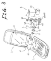
- the photographing part 6 in this embodiment has, as shown in Figs. 2 and 3, a lens barrel 61 for fixing a lens 60, a holder 62 for holding the lens barrel 61 which is divided into an upper part and a lower part, a cap 63 for covering this holder 62 from a side, a lens cover 64, and a ring 65 for retaining the cap 63 from withdrawal.
- the holder 62 is composed of an upper holder 62A and a lower holder 62B joined together, and in a hollow space formed therebetween, there is contained the photographing (image forming) lens 60 fixed to the lens barrel 61 placed on a cushion material 68.
- a CCD which is not shown
- a printed circuit board 66 mounting this CCD are placed on a focal point of the lens 60, inside this holder 62.
- a flexible circuit board 67 is drawn out from this printed circuit board 66 for electrical connection between the CCD in the photographing part 6 and a printed circuit board in the upper case 2 (or in the lower case 1) which is not shown.
- this flexible circuit board 67 is drawn out toward the hinge part 3, by way of a joint face between the upper holder 62A and the lower holder 62B, as shown in Fig. 4.
- the cap 63 is provided with an open window 63A for making a light from an object to be photographed incident on the lens 60. With the opening and closing motions of the upper case 2 or rotating manipulation of the cap 63 clamped with fingers or the like, the photographing direction can be freely changed and set within a determined angle range.
- the association mechanism 7 is intended to make the lens 60 exposed from the upper and lower cases 1 and 2 to the exterior, or received inside the upper and lower cases 1 and 2, and adapted to rotate the photographing part 6 in association with the opening and closing motions of the upper case 2 or manipulate the photographing part 6 to rotate with fingers or the like, as described above.
- this association mechanism 7 has the connecting member 71 which is fitted around a tubular portion 62C extending from a side of the holder 62 of the photographing part 6, the collar 72 which is fitted around this connecting member 71, and the E-ring (or C-ring) 73.
- the connecting member 71 is intended to hold the photographing part 6 so as to rotate with respect to the hinge part 3 and to rotate the photographing part 6 integrally with the upper case 2 with friction force ( ⁇ ).
- the connecting member 71 constitutes the member to be restricted from rotation so that the rotary movement of the photographing part 6 with respect to the lower case 1 may be allowed only within a certain range.
- this connecting member 71 is provided with a cut-out 71A, as shown in Fig. 3, along a part of its outer circumference, in such a manner that an area corresponding to 45 degree of the central angle is cut away. When either face of this cut-out 71A is locked with either of the above described stoppers of the restricting member, further rotation of the connecting member 71 will be blocked.
- the connecting member 71 moves in association with the upper case 2 until it is locked by the stopper of the restricting member. However, being locked in this manner, the connecting member 71 will no more move in association with the upper case 2, but the upper case 2 only will continue to rotate.
- the connecting member 71 will make the rotary movement from the position held, in association with the upper case 2. Because this connecting member 71 is locked with the stopper of the restricting member from the rotation over a certain angle, the lens 60 in the photographing part 6 which rotates integrally with the connecting member 71 is always directed to a position within the predetermined angle range with respect to the upper case 2, when the upper case 2 is opened. In this manner, work for adjusting the position of the lens 60 when the upper case 2 is opened can be simplified, and operability of the lens can be enhanced.
- the collar 72 is interposed between an inner peripheral face of the second rotary part 42 constituting a part of the lower hinge part 4 which is integrally provided with the interior frame 1C of the lower case 1, and an outer peripheral face of the connecting member 71.
- This collar 72 constitutes the second friction member.
- this collar 72 is formed of appropriate metal material, and designed in such a manner that when the upper case 2 performs the rotary movement, the socket portion 53 integral with the upper case 2 and further, the connecting member 71 may rotate in a rotatable state relative to this collar 72.
- this collar 72 has a maximum friction coefficient of ⁇ 1 with respect to the inner peripheral face of the second rotary part 42, and a maximum friction coefficient of ⁇ 2 with respect to the outer peripheral face of the connecting member 71
- the below described E-ring 73 has the following relations to maximum friction coefficients ⁇ 3 and ⁇ 4 with respect to the socket portion 53 adjacent to the upper case 2 and the tubular portion 62C of the holder 62. ⁇ 1 ⁇ ⁇ 3 ⁇ 2 ⁇ ⁇ 3 or ⁇ 1 > ⁇ 4 ⁇ 2 > ⁇ 4
- the E-ring 73 is formed in a substantially cylindrical shape, and interposed between the socket portion 53 adjacent to the upper case 2 which is pressure fitted to the inner peripheral face of the first rotary part 51 constituting a part of the upper hinge 5, and the tubular portion 62C of the holder 62. Specifically, this E-ring is engaged in a groove 62D of the tubular portion 62C of the holder 62 and engaged in a groove 53A formed in the socket portion 53 adjacent to the upper case 2 to serve as a retention for the photographing part 6 from withdrawal.
- this E-ring 73 is provided with bulging portions 73A projected in a flange-like shape on both faces of its edge, and the bulging portions 73A are adapted to come into a linear contact with the groove in the socket portion 53.
- this E-ring 73 constitutes the first friction member, because the E-ring 73 rotates integrally with the socket portion 53 (further with the connecting member 71) by means of the friction power with respect to the socket portion 53 integrated with the upper case 2, when the upper case 2 performs the rotary movement.
- the friction coefficient of the E-ring 73 is set to be larger than that of the collar 72 which is the second friction member.
- this E-ring is so designed that the above described relations (1) and (2) or (3) and (4) may be satisfied, provided that the friction coefficients of this E-ring with respect to the socket portion 53 adjacent to the upper case 2 and the tubular portion 62C of the holder 62 are respectively ⁇ 3 and ⁇ 4.
- the maximum friction forces with respect to the socket portion 53 and the tubular portion 62C of the holder 62 are set to be smaller than the manipulation force for rotating them with fingers, and thus, the operator can reliably operate the photographing part 6 to rotate by the manipulation with the fingers.
- the E-ring 73 in this embodiment is formed of appropriate synthetic resin material having resiliency to a certain extent in a radial direction, and adapted to ride over the stopper 53B provided in the socket portion 53 so that the E-ring can be engaged in the groove 53A which is formed inward of the stopper 53B.
- the open window 63A of the lens in the photographing part 6 is positioned at a joint face between both inner faces of the lower case 1 and the upper case 2.
- the open window 63A is completely covered with both the cases so that an exterior light cannot enter into the open window 63A, and thus, it is impossible to photograph.
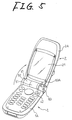
- the operator wants to send, for example, an image of the operator himself to a third person, he will first open the mobile phone set which has been folded. Specifically, he goes on opening the upper case 2, holding the lower case 1 with his one hand, while the upper case 2 is grasped by the other hand. With this operation, by way of the association mechanism 7 which moves in association with the rotary movement of the upper case 2, the photographing part 6 also is rotated by the same angle in the same direction, as shown in Fig. 5.
- the first rotary part 51 integral with this upper case 2 and the socket portion 53 which is pressure fitted to the inner peripheral face thereof will go on rotating simultaneously in the same direction. Accordingly, the E-ring 73 in contact with the socket portion 53 in Fig. 2, will be rotated integrally with the socket portion 53 with the friction force, and by way of this E-ring 73, the holder 62 and further, the photographing part 6 are rotated integrally with the upper case 2.
- the holder 62 of the photographing part 6 can be rotated at the same angle by operating to rotate only the upper case 2. With this operation, the fine adjustment can be performed more easily as compared with the case in which the adjustment is carried out by grasping the small holder 62 with fingers. This is because the outermost edge of the upper case 2 which is remote from the rotation axis can ensure a larger stroke with respect to the same rotation angle than the small holder 62 which is close to the rotation axis.
- the fine angle adjustment can be conducted by grasping the photographing part 6 with one hand while the lower case 1 or the upper case 2 is fixed with the other hand, and by operating the photographing part 6 for rotation.
- the upper case 1 can be simply rotated toward the lower case 2 so as to be folded.
- the photographing part 6 is rotated in association with the upper case 1, and the open window 63A will be completely covered with the upper case 1 and the lower case 2.
- a trouble that the open window 63A may get dirty or broken can be prevented.
- the open window 63A is completely covered with the upper case 1 and the lower case 2, even in the case where an off operation of the power is forgotten, it is also possible to prevent such a trouble that an unnecessary picture is taken by the photographing part 6 unconsciously, and transmitted to a third person.
- the mobile terminal device with the camera comprising the lower case provided with the operating part, the upper case provided with the display part, the hinge part for connecting the upper case with the lower case in a foldable manner, and the photographing part rotatably installed in the hinge part, in which there is provided the association mechanism which can rotate the photographing part in association with opening and closing motions of the upper case.
- the orientation of the camera can be easily adjusted in association with the opening and closing motions of the upper case, and after the photographing operation of the camera has been finished, the camera can be automatically closed in association with the folding motion of the cases of the mobile terminal device. Accordingly, the camera can be protected from the exterior, and such a trouble that the lens or the cover glass of the camera may get dirty or broken while being carried can be prevented. Thus, reliability of the mobile terminal device can be enhanced.
Landscapes
- Engineering & Computer Science (AREA)
- Signal Processing (AREA)
- Multimedia (AREA)
- Human Computer Interaction (AREA)
- Telephone Set Structure (AREA)
- Studio Devices (AREA)
Abstract
Description
Claims (7)
- A mobile terminal device with a camera comprising a lower case provided with an operating part, an upper case provided with a display part, a hinge part for connecting said upper case with said lower case in a foldable manner, and a photographing part installed in said hinge part,
wherein there is provided an association mechanism by which said photographing part is rotated in association with opening and closing motions of said upper case. - The mobile terminal device with a camera as claimed in claim 1,
wherein said hinge part includes an upper hinge which is integral with said upper case and a lower hinge which is integral with said lower case, and
wherein said association mechanism includes a first friction member provided between said upper hinge and said photographing part, and
wherein said first friction member has friction coefficient which is larger than friction coefficient between said lower hinge and said photographing part. - The mobile terminal device with a camera as claimed in claim 2,
wherein said association mechanism includes a second friction member provided between said first friction member, said lower hinge and said photographing part, and
wherein the friction coefficient of said first friction member is larger than friction coefficient of said second friction member. - The mobile terminal device with a camera as claimed in claim 2 or 3, wherein said first friction member includes a C-ring or an E-ring.
- The mobile terminal device with a camera as claimed in claim 4, wherein said C-ring or E-ring is provided with a bulging portion on a circumferential edge, said bulging portion being adapted to come into a point contact with said upper hinge.
- The mobile terminal device with a camera as claimed in claim 2,
wherein said upper hinge and said lower hinge are provided with restricting members for restricting rotation range of said photographing part, and
wherein said photographing part is provided with a member to be restricted by said restricting member so that said rotation range of said photographing part is restricted. - The mobile terminal device with a camera as claimed in any one of claims 1 to 6,
wherein a housing of said photographing part is formed by joining an upper housing and a lower housing, and
a flexible circuit board for electrical connection between an interior of said photographing part and said upper or lower case is drawn out through a joint portion between said upper and lower housings.
Applications Claiming Priority (3)
| Application Number | Priority Date | Filing Date | Title |
|---|---|---|---|
| JP2001164923 | 2001-05-31 | ||
| JP2001164923A JP3483144B2 (en) | 2001-05-31 | 2001-05-31 | Mobile terminal with camera |
| PCT/JP2002/003778 WO2002100077A1 (en) | 2001-05-31 | 2002-04-16 | Portable terminal device with camera |
Publications (3)
| Publication Number | Publication Date |
|---|---|
| EP1392038A1 true EP1392038A1 (en) | 2004-02-25 |
| EP1392038A4 EP1392038A4 (en) | 2005-11-16 |
| EP1392038B1 EP1392038B1 (en) | 2008-07-23 |
Family
ID=19007667
Family Applications (1)
| Application Number | Title | Priority Date | Filing Date |
|---|---|---|---|
| EP02717179A Expired - Lifetime EP1392038B1 (en) | 2001-05-31 | 2002-04-16 | Portable terminal device with camera |
Country Status (6)
| Country | Link |
|---|---|
| US (1) | US6879337B2 (en) |
| EP (1) | EP1392038B1 (en) |
| JP (1) | JP3483144B2 (en) |
| CN (1) | CN1215693C (en) |
| DE (1) | DE60227801D1 (en) |
| WO (1) | WO2002100077A1 (en) |
Cited By (5)
| Publication number | Priority date | Publication date | Assignee | Title |
|---|---|---|---|---|
| EP1494437A1 (en) * | 2003-07-04 | 2005-01-05 | LG Electronics Inc. | Rotary camera for mobile communication device |
| WO2006007221A1 (en) * | 2004-06-21 | 2006-01-19 | Motorola, Inc. | Communication device including one or more electrical control buttons in an upper housing part |
| WO2006007215A1 (en) * | 2004-06-21 | 2006-01-19 | Motorola, Inc. | Communication device including one or more electrical control buttons in an upper housing part |
| WO2006007222A1 (en) * | 2004-06-21 | 2006-01-19 | Motorola, Inc. | Mechanical layout and component placement for thin clamshell phone |
| CN101485180B (en) * | 2006-06-30 | 2012-09-12 | 摩托罗拉移动公司 | Electronic device having a single-split hinge |
Families Citing this family (47)
| Publication number | Priority date | Publication date | Assignee | Title |
|---|---|---|---|---|
| US6781824B2 (en) * | 2002-01-29 | 2004-08-24 | Palm, Inc. | Encasement for handheld computer |
| US20030142471A1 (en) * | 2002-01-29 | 2003-07-31 | Palm, Inc. | Replaceable cover for handheld computer |
| JP3882687B2 (en) * | 2002-06-11 | 2007-02-21 | 日本電気株式会社 | Portable communication device |
| KR100672095B1 (en) * | 2002-06-26 | 2007-01-19 | 교세라 가부시키가이샤 | Portable terminal device with an imaging function |
| KR100459543B1 (en) * | 2002-07-10 | 2004-12-03 | 삼성전자주식회사 | Camera lens module and portable wireless terminal therewith |
| JP2004120670A (en) * | 2002-09-30 | 2004-04-15 | Hitachi Ltd | Foldable portable terminal device |
| KR100455776B1 (en) * | 2002-11-18 | 2004-11-06 | 엘지전자 주식회사 | A mobile telecommunication terminal having a camera |
| KR100487616B1 (en) * | 2002-11-29 | 2005-05-03 | 엘지전자 주식회사 | Folder type mobile phone |
| JP4233855B2 (en) * | 2002-11-29 | 2009-03-04 | 京セラ株式会社 | Mobile terminal device |
| JP2004214946A (en) | 2002-12-27 | 2004-07-29 | Casio Comput Co Ltd | Foldable portable information device |
| CN1305336C (en) * | 2003-03-19 | 2007-03-14 | 三星电子株式会社 | Camera lens in portable radio terminal |
| US7619686B2 (en) * | 2003-03-24 | 2009-11-17 | Kantan Inc. | Apparatus for a combination camcorder-handset device |
| JP4112414B2 (en) * | 2003-03-28 | 2008-07-02 | 京セラ株式会社 | Mobile terminal device |
| JP4188867B2 (en) * | 2003-04-14 | 2008-12-03 | 三星電子株式会社 | Portable terminal equipped with a rotating camera lens housing |
| TW588902U (en) * | 2003-04-25 | 2004-05-21 | Hon Hai Prec Ind Co Ltd | Lens module for a communication unit |
| KR100548339B1 (en) * | 2003-04-30 | 2006-02-02 | 엘지전자 주식회사 | Camera device of portable terminal |
| KR100548343B1 (en) * | 2003-05-12 | 2006-02-02 | 엘지전자 주식회사 | Camera Fixer in Mobile Phone |
| JP2005026868A (en) * | 2003-06-30 | 2005-01-27 | Toshiba Corp | Audio signal recording device |
| KR100739564B1 (en) | 2003-07-31 | 2007-07-16 | 엘지전자 주식회사 | Mobile terminal with camera |
| KR100557084B1 (en) * | 2003-08-21 | 2006-03-03 | 삼성전자주식회사 | Camera lens assembly in portable wireless terminal |
| JP3982760B2 (en) * | 2003-09-19 | 2007-09-26 | 日本航空電子工業株式会社 | Hinge device for electronic equipment |
| JP4048435B2 (en) | 2003-10-23 | 2008-02-20 | ソニー株式会社 | Electronics |
| KR100575746B1 (en) | 2003-10-28 | 2006-05-03 | 엘지전자 주식회사 | Clamshell terminal |
| US20050099533A1 (en) * | 2003-11-10 | 2005-05-12 | Casio Computer Co., Ltd. | Image capturing apparatus and camera module |
| KR100565309B1 (en) * | 2003-11-25 | 2006-03-30 | 엘지전자 주식회사 | Microphone switching device and method of a mobile communication terminal having a camcorder function |
| KR100792920B1 (en) | 2003-11-26 | 2008-01-08 | 샤프 가부시키가이샤 | Folding mobile terminal |
| JP2005208428A (en) * | 2004-01-23 | 2005-08-04 | Sony Corp | Rotating hinge mechanism and imaging device |
| TWI230535B (en) * | 2004-02-20 | 2005-04-01 | Benq Corp | Rotary apparatus having digital camera module |
| CN100442828C (en) * | 2004-03-09 | 2008-12-10 | 明基电通股份有限公司 | Rotating device with digital camera module and electronic device comprising same |
| KR100617688B1 (en) | 2004-05-19 | 2006-08-28 | 삼성전자주식회사 | Hinge device of a mobile terminal |
| TWM264768U (en) * | 2004-06-18 | 2005-05-11 | Fih Co Ltd | Multi-segtion hinge mechanism |
| US8095073B2 (en) * | 2004-06-22 | 2012-01-10 | Sony Ericsson Mobile Communications Ab | Method and apparatus for improved mobile station and hearing aid compatibility |
| JP2006060396A (en) * | 2004-08-18 | 2006-03-02 | Fujitsu Ltd | Mobile terminal device |
| KR100604323B1 (en) * | 2004-08-28 | 2006-07-24 | 삼성테크윈 주식회사 | Built-in camera device and mobile phone with same |
| JP4224712B2 (en) * | 2004-09-24 | 2009-02-18 | 日本電気株式会社 | Foldable mobile phone device and method for assembling the same |
| US7184803B2 (en) * | 2005-01-21 | 2007-02-27 | Inventec Corporation | Apparatus for automatically projecting or retracting lens in response to the display of an electronic device incorporating the apparatus being opened or closed |
| KR100667531B1 (en) * | 2005-03-09 | 2007-01-10 | 엘지전자 주식회사 | Foldable mobile phone that shake of folder part is prevented |
| KR100703353B1 (en) * | 2005-05-30 | 2007-04-03 | 삼성전자주식회사 | Portable terminal with camera lens assembly |
| US7554523B2 (en) * | 2005-07-25 | 2009-06-30 | Inventec Corporation | Peripheral device for image display apparatus |
| US20070109410A1 (en) * | 2005-11-15 | 2007-05-17 | Creative Technology Ltd. | Apparatus for audio reproduction and image capturing |
| KR100653212B1 (en) | 2005-11-17 | 2006-12-05 | 주식회사 팬택 | Personal handheld terminal using clamshell hinge device and clamshell hinge device |
| KR100762640B1 (en) * | 2006-07-18 | 2007-10-01 | 삼성전자주식회사 | Mobile terminal and method for automatically selecting a shooting mode |
| TWI386009B (en) * | 2007-01-22 | 2013-02-11 | Hon Hai Prec Ind Co Ltd | A portable electronic device having a function for photo-taking |
| EP3457249B1 (en) * | 2011-12-30 | 2021-04-14 | Samsung Electronics Co., Ltd. | Display apparatus |
| JP6675839B2 (en) * | 2015-07-27 | 2020-04-08 | 三菱マヒンドラ農機株式会社 | Combine |
| US10013031B2 (en) * | 2016-09-30 | 2018-07-03 | Dell Products L.P. | Systems and methods for mechanically interfacing camera to hinge of information handling system |
| CN115507264B (en) * | 2022-09-30 | 2025-02-21 | 联想(北京)有限公司 | Electronic equipment |
Family Cites Families (8)
| Publication number | Priority date | Publication date | Assignee | Title |
|---|---|---|---|---|
| JP3255995B2 (en) * | 1992-10-23 | 2002-02-12 | 株式会社日立製作所 | Videophone equipment |
| JPH1065780A (en) * | 1996-08-22 | 1998-03-06 | Hitachi Ltd | Mobile phone with videophone function |
| JP3516328B2 (en) * | 1997-08-22 | 2004-04-05 | 株式会社日立製作所 | Information communication terminal equipment |
| KR100274623B1 (en) * | 1997-12-23 | 2000-12-15 | 윤종용 | Digital still camera |
| JP3093727B2 (en) * | 1998-05-21 | 2000-10-03 | 日本電気株式会社 | Electronics |
| JP3265572B2 (en) * | 1998-11-20 | 2002-03-11 | 日本電気株式会社 | Switchgear for folding mobile phone |
| JP2000253113A (en) * | 1999-02-26 | 2000-09-14 | Hitachi Ltd | Information communication terminal equipment |
| JP2000253124A (en) * | 1999-03-01 | 2000-09-14 | Matsushita Electric Ind Co Ltd | Information portable terminal with imaging function |
-
2001
- 2001-05-31 JP JP2001164923A patent/JP3483144B2/en not_active Expired - Fee Related
-
2002
- 2002-04-16 DE DE60227801T patent/DE60227801D1/en not_active Expired - Lifetime
- 2002-04-16 EP EP02717179A patent/EP1392038B1/en not_active Expired - Lifetime
- 2002-04-16 WO PCT/JP2002/003778 patent/WO2002100077A1/en not_active Ceased
- 2002-04-16 CN CNB028019970A patent/CN1215693C/en not_active Expired - Fee Related
- 2002-08-16 US US10/344,864 patent/US6879337B2/en not_active Expired - Fee Related
Cited By (7)
| Publication number | Priority date | Publication date | Assignee | Title |
|---|---|---|---|---|
| EP1494437A1 (en) * | 2003-07-04 | 2005-01-05 | LG Electronics Inc. | Rotary camera for mobile communication device |
| US7567283B2 (en) | 2003-07-04 | 2009-07-28 | Lg Electronics Inc. | Rotary camera for mobile communication device |
| WO2006007221A1 (en) * | 2004-06-21 | 2006-01-19 | Motorola, Inc. | Communication device including one or more electrical control buttons in an upper housing part |
| WO2006007215A1 (en) * | 2004-06-21 | 2006-01-19 | Motorola, Inc. | Communication device including one or more electrical control buttons in an upper housing part |
| WO2006007222A1 (en) * | 2004-06-21 | 2006-01-19 | Motorola, Inc. | Mechanical layout and component placement for thin clamshell phone |
| US7274954B2 (en) | 2004-06-21 | 2007-09-25 | Motorola, Inc. | Communication device including one or more electrical control buttons in an upper housing part |
| CN101485180B (en) * | 2006-06-30 | 2012-09-12 | 摩托罗拉移动公司 | Electronic device having a single-split hinge |
Also Published As
| Publication number | Publication date |
|---|---|
| EP1392038B1 (en) | 2008-07-23 |
| DE60227801D1 (en) | 2008-09-04 |
| JP2002359678A (en) | 2002-12-13 |
| US20040051779A1 (en) | 2004-03-18 |
| EP1392038A4 (en) | 2005-11-16 |
| CN1215693C (en) | 2005-08-17 |
| WO2002100077A1 (en) | 2002-12-12 |
| CN1463530A (en) | 2003-12-24 |
| JP3483144B2 (en) | 2004-01-06 |
| US6879337B2 (en) | 2005-04-12 |
Similar Documents
| Publication | Publication Date | Title |
|---|---|---|
| US6879337B2 (en) | Portable terminal device with camera | |
| JP4578727B2 (en) | Information terminal device provided with camera with rotation function | |
| JP4188867B2 (en) | Portable terminal equipped with a rotating camera lens housing | |
| KR100449451B1 (en) | Camera lens mounting device of folder type telephone | |
| US7246955B2 (en) | Automatic camera lens module retracting/extending apparatus for mobile communication terminals | |
| EP1578113B1 (en) | Camera lens module pop-up device for portable wireless terminal | |
| EP1494437B1 (en) | Rotary camera for mobile communication device | |
| US20050195322A1 (en) | Camera lens assembly and portable terminal having the same | |
| US7422380B2 (en) | Camera door opening/shutting apparatus for portable terminal | |
| EP1843589B1 (en) | Camera lens assembly for portable wireless terminals | |
| JP3874750B2 (en) | Foldable mobile terminal with slide function | |
| JP4024175B2 (en) | Mobile communication device with imaging unit | |
| KR200342944Y1 (en) | Camera apparatus for mobile phone | |
| KR20040037692A (en) | Mobile phone with built-in camera | |
| JP2005109538A (en) | Folding mobile phone with camera | |
| KR100498357B1 (en) | Camera apparatus in mobile phone | |
| JP2004170558A (en) | Personal digital assistance device | |
| CN203747895U (en) | Shell structure and electronic equipment | |
| JP2005167876A (en) | Folding type portable digital terminal device | |
| KR20060033540A (en) | Sliding mobile communication terminal with camera module capable of automatic rotation control | |
| KR20050095450A (en) | Mobile communication terminal having rotating type camera |
Legal Events
| Date | Code | Title | Description |
|---|---|---|---|
| PUAI | Public reference made under article 153(3) epc to a published international application that has entered the european phase |
Free format text: ORIGINAL CODE: 0009012 |
|
| 17P | Request for examination filed |
Effective date: 20030213 |
|
| AK | Designated contracting states |
Kind code of ref document: A1 Designated state(s): AT BE CH CY DE DK ES FI FR GB GR IE IT LI LU MC NL PT SE TR |
|
| AX | Request for extension of the european patent |
Extension state: AL LT LV MK RO SI |
|
| A4 | Supplementary search report drawn up and despatched |
Effective date: 20050929 |
|
| 17Q | First examination report despatched |
Effective date: 20070824 |
|
| GRAP | Despatch of communication of intention to grant a patent |
Free format text: ORIGINAL CODE: EPIDOSNIGR1 |
|
| GRAS | Grant fee paid |
Free format text: ORIGINAL CODE: EPIDOSNIGR3 |
|
| GRAA | (expected) grant |
Free format text: ORIGINAL CODE: 0009210 |
|
| AK | Designated contracting states |
Kind code of ref document: B1 Designated state(s): DE FR GB |
|
| REG | Reference to a national code |
Ref country code: GB Ref legal event code: FG4D |
|
| REF | Corresponds to: |
Ref document number: 60227801 Country of ref document: DE Date of ref document: 20080904 Kind code of ref document: P |
|
| RAP2 | Party data changed (patent owner data changed or rights of a patent transferred) |
Owner name: PANASONIC CORPORATION |
|
| PLBE | No opposition filed within time limit |
Free format text: ORIGINAL CODE: 0009261 |
|
| STAA | Information on the status of an ep patent application or granted ep patent |
Free format text: STATUS: NO OPPOSITION FILED WITHIN TIME LIMIT |
|
| 26N | No opposition filed |
Effective date: 20090424 |
|
| GBPC | Gb: european patent ceased through non-payment of renewal fee |
Effective date: 20090416 |
|
| REG | Reference to a national code |
Ref country code: FR Ref legal event code: ST Effective date: 20091231 |
|
| PG25 | Lapsed in a contracting state [announced via postgrant information from national office to epo] |
Ref country code: GB Free format text: LAPSE BECAUSE OF NON-PAYMENT OF DUE FEES Effective date: 20090416 Ref country code: FR Free format text: LAPSE BECAUSE OF NON-PAYMENT OF DUE FEES Effective date: 20091222 |
|
| PGFP | Annual fee paid to national office [announced via postgrant information from national office to epo] |
Ref country code: DE Payment date: 20120425 Year of fee payment: 11 |
|
| PG25 | Lapsed in a contracting state [announced via postgrant information from national office to epo] |
Ref country code: DE Free format text: LAPSE BECAUSE OF NON-PAYMENT OF DUE FEES Effective date: 20131101 |
|
| REG | Reference to a national code |
Ref country code: DE Ref legal event code: R119 Ref document number: 60227801 Country of ref document: DE Effective date: 20131101 |