EP1391913A1 - Fluorescent lamp and amalgam assembly therefor - Google Patents
Fluorescent lamp and amalgam assembly therefor Download PDFInfo
- Publication number
- EP1391913A1 EP1391913A1 EP03016255A EP03016255A EP1391913A1 EP 1391913 A1 EP1391913 A1 EP 1391913A1 EP 03016255 A EP03016255 A EP 03016255A EP 03016255 A EP03016255 A EP 03016255A EP 1391913 A1 EP1391913 A1 EP 1391913A1
- Authority
- EP
- European Patent Office
- Prior art keywords
- tubulation
- amalgam
- lamp
- accordance
- assembly
- Prior art date
- Legal status (The legal status is an assumption and is not a legal conclusion. Google has not performed a legal analysis and makes no representation as to the accuracy of the status listed.)
- Granted
Links
- 229910000497 Amalgam Inorganic materials 0.000 title claims abstract description 208
- 239000011521 glass Substances 0.000 claims abstract description 77
- QSHDDOUJBYECFT-UHFFFAOYSA-N mercury Chemical compound [Hg] QSHDDOUJBYECFT-UHFFFAOYSA-N 0.000 claims abstract description 55
- 229910052753 mercury Inorganic materials 0.000 claims abstract description 35
- 238000009736 wetting Methods 0.000 claims abstract description 21
- 230000000717 retained effect Effects 0.000 claims abstract description 13
- 229910052751 metal Inorganic materials 0.000 claims description 43
- 239000002184 metal Substances 0.000 claims description 43
- WHXSMMKQMYFTQS-UHFFFAOYSA-N Lithium Chemical compound [Li] WHXSMMKQMYFTQS-UHFFFAOYSA-N 0.000 claims description 34
- 229910052744 lithium Inorganic materials 0.000 claims description 34
- 239000007788 liquid Substances 0.000 claims description 28
- 230000005855 radiation Effects 0.000 claims description 24
- 239000000080 wetting agent Substances 0.000 claims description 18
- APFVFJFRJDLVQX-UHFFFAOYSA-N indium atom Chemical compound [In] APFVFJFRJDLVQX-UHFFFAOYSA-N 0.000 claims description 17
- 229910052738 indium Inorganic materials 0.000 claims description 16
- 238000000576 coating method Methods 0.000 claims description 15
- 239000011248 coating agent Substances 0.000 claims description 14
- 229910045601 alloy Inorganic materials 0.000 claims description 12
- 239000000956 alloy Substances 0.000 claims description 12
- OAICVXFJPJFONN-UHFFFAOYSA-N Phosphorus Chemical compound [P] OAICVXFJPJFONN-UHFFFAOYSA-N 0.000 claims description 10
- JCXGWMGPZLAOME-UHFFFAOYSA-N bismuth atom Chemical compound [Bi] JCXGWMGPZLAOME-UHFFFAOYSA-N 0.000 claims description 10
- 230000005284 excitation Effects 0.000 claims description 9
- HCHKCACWOHOZIP-UHFFFAOYSA-N Zinc Chemical compound [Zn] HCHKCACWOHOZIP-UHFFFAOYSA-N 0.000 claims description 8
- 238000010891 electric arc Methods 0.000 claims description 8
- 239000011701 zinc Substances 0.000 claims description 8
- 239000000203 mixture Substances 0.000 claims description 7
- 229910052725 zinc Inorganic materials 0.000 claims description 7
- 229910052709 silver Inorganic materials 0.000 claims description 6
- 239000004332 silver Substances 0.000 claims description 6
- 230000009969 flowable effect Effects 0.000 claims description 5
- 230000002093 peripheral effect Effects 0.000 claims description 5
- 239000007787 solid Substances 0.000 claims description 5
- 229910001030 Iron–nickel alloy Inorganic materials 0.000 claims description 3
- BQCADISMDOOEFD-UHFFFAOYSA-N Silver Chemical compound [Ag] BQCADISMDOOEFD-UHFFFAOYSA-N 0.000 claims description 3
- PCHJSUWPFVWCPO-UHFFFAOYSA-N gold Chemical compound [Au] PCHJSUWPFVWCPO-UHFFFAOYSA-N 0.000 claims description 3
- 229910052737 gold Inorganic materials 0.000 claims description 3
- 239000010931 gold Substances 0.000 claims description 3
- 239000010935 stainless steel Substances 0.000 claims description 3
- ATJFFYVFTNAWJD-UHFFFAOYSA-N Tin Chemical compound [Sn] ATJFFYVFTNAWJD-UHFFFAOYSA-N 0.000 claims 9
- 229910052797 bismuth Inorganic materials 0.000 claims 9
- 229910052718 tin Inorganic materials 0.000 claims 9
- 229910001220 stainless steel Inorganic materials 0.000 claims 2
- PRPINYUDVPFIRX-UHFFFAOYSA-N 1-naphthaleneacetic acid Chemical group C1=CC=C2C(CC(=O)O)=CC=CC2=C1 PRPINYUDVPFIRX-UHFFFAOYSA-N 0.000 description 4
- 230000014759 maintenance of location Effects 0.000 description 4
- 238000004519 manufacturing process Methods 0.000 description 4
- 229910001128 Sn alloy Inorganic materials 0.000 description 3
- XKRFYHLGVUSROY-UHFFFAOYSA-N Argon Chemical compound [Ar] XKRFYHLGVUSROY-UHFFFAOYSA-N 0.000 description 2
- 229910000846 In alloy Inorganic materials 0.000 description 2
- 229910000733 Li alloy Inorganic materials 0.000 description 2
- 238000010276 construction Methods 0.000 description 2
- 230000001419 dependent effect Effects 0.000 description 2
- 230000005484 gravity Effects 0.000 description 2
- 239000001989 lithium alloy Substances 0.000 description 2
- 239000000463 material Substances 0.000 description 2
- 229940008718 metallic mercury Drugs 0.000 description 2
- 150000002739 metals Chemical class 0.000 description 2
- 229910001152 Bi alloy Inorganic materials 0.000 description 1
- 229910001297 Zn alloy Inorganic materials 0.000 description 1
- 229910052786 argon Inorganic materials 0.000 description 1
- MPZNMEBSWMRGFG-UHFFFAOYSA-N bismuth indium Chemical compound [In].[Bi] MPZNMEBSWMRGFG-UHFFFAOYSA-N 0.000 description 1
- 230000007423 decrease Effects 0.000 description 1
- 230000002939 deleterious effect Effects 0.000 description 1
- 230000000694 effects Effects 0.000 description 1
- 239000007789 gas Substances 0.000 description 1
- 239000007792 gaseous phase Substances 0.000 description 1
- 238000007373 indentation Methods 0.000 description 1
- 239000011810 insulating material Substances 0.000 description 1
- 229910052743 krypton Inorganic materials 0.000 description 1
- DNNSSWSSYDEUBZ-UHFFFAOYSA-N krypton atom Chemical compound [Kr] DNNSSWSSYDEUBZ-UHFFFAOYSA-N 0.000 description 1
- 230000007257 malfunction Effects 0.000 description 1
- 230000008018 melting Effects 0.000 description 1
- 238000002844 melting Methods 0.000 description 1
- 229910001092 metal group alloy Inorganic materials 0.000 description 1
- 230000005012 migration Effects 0.000 description 1
- 238000013508 migration Methods 0.000 description 1
- 230000003595 spectral effect Effects 0.000 description 1
- 229910001256 stainless steel alloy Inorganic materials 0.000 description 1
Images


Classifications
-
- H—ELECTRICITY
- H01—ELECTRIC ELEMENTS
- H01J—ELECTRIC DISCHARGE TUBES OR DISCHARGE LAMPS
- H01J61/00—Gas-discharge or vapour-discharge lamps
- H01J61/02—Details
- H01J61/24—Means for obtaining or maintaining the desired pressure within the vessel
-
- H—ELECTRICITY
- H01—ELECTRIC ELEMENTS
- H01J—ELECTRIC DISCHARGE TUBES OR DISCHARGE LAMPS
- H01J61/00—Gas-discharge or vapour-discharge lamps
- H01J61/02—Details
- H01J61/24—Means for obtaining or maintaining the desired pressure within the vessel
- H01J61/28—Means for producing, introducing, or replenishing gas or vapour during operation of the lamp
-
- H—ELECTRICITY
- H01—ELECTRIC ELEMENTS
- H01J—ELECTRIC DISCHARGE TUBES OR DISCHARGE LAMPS
- H01J61/00—Gas-discharge or vapour-discharge lamps
- H01J61/70—Lamps with low-pressure unconstricted discharge having a cold pressure < 400 Torr
- H01J61/72—Lamps with low-pressure unconstricted discharge having a cold pressure < 400 Torr having a main light-emitting filling of easily vaporisable metal vapour, e.g. mercury
-
- H—ELECTRICITY
- H01—ELECTRIC ELEMENTS
- H01J—ELECTRIC DISCHARGE TUBES OR DISCHARGE LAMPS
- H01J65/00—Lamps without any electrode inside the vessel; Lamps with at least one main electrode outside the vessel
- H01J65/04—Lamps in which a gas filling is excited to luminesce by an external electromagnetic field or by external corpuscular radiation, e.g. for indicating plasma display panels
- H01J65/042—Lamps in which a gas filling is excited to luminesce by an external electromagnetic field or by external corpuscular radiation, e.g. for indicating plasma display panels by an external electromagnetic field
- H01J65/048—Lamps in which a gas filling is excited to luminesce by an external electromagnetic field or by external corpuscular radiation, e.g. for indicating plasma display panels by an external electromagnetic field the field being produced by using an excitation coil
Definitions
- This invention relates to fluorescent lamps and is directed more particularly to an amalgam assembly, and more particularly including an improved amalgam for use within an exhaust tubulation of a fluorescent lamp, and to a fluorescent lamp including the amalgam assembly.
- the fluorescent lamp may be for example linear, or compact, and with or without electrodes.
- Fluorescent lamps typically include at least one tubulation that has an opening into the interior of the lamp envelope and which, in construction of the lamp, is used as an exhaust and fill tubulation. At completion of manufacture, the exhaust tubulation is hermetically tipped off and the tipped end typically becomes the lamp "cold spot".
- the amalgam is commonly located in the exhaust tubulation cold spot. Such amalgams reduce the mercury vapor pressure relative to that of pure mercury at any given temperature and thereby permit optimum light output at elevated temperatures. Such amalgams also provide a broadened peak in the light output versus temperature curve, so that near optimum light output is obtained over an extended range of ambient temperatures.
- Alloys of low temperature melting metals are often placed within fluorescent lamps to amalgamate with the excess mercury, and to regulate the mercury vapor pressure within the lamp.
- Alloys known to be particularly useful in forming amalgams with mercury include a lead-bismuth-tin alloy, a bismuth-indium alloy, a bismuth and tin alloy, and a zinc, indium and tin alloy, see for example WO 96/37909 and EP 373 567.
- Other useful amalgams may be formed with pure indium, pure lead, and pure zinc.
- the lamp typically is provided with an excess amount of mercury amalgam, that is, more amalgam than is needed to supply the mercury vaporized when the lamp reaches a stabilized operating condition. As the lamp ages, some of the excess amalgam is required to replace the mercury chemically bound elsewhere in the lamp during the life of the lamp.
- amalgam fluorescent lamp When an amalgam fluorescent lamp is turned off, the amalgam cools and the mercury vapor within the lamp is gradually absorbed into the amalgam. When the lamp is turned on, the lumen output is significantly reduced until the amalgam is warmed up to a point at which the amalgam emits sufficient mercury vapor to permit efficient lamp operation.
- the amalgam be prevented from settling within the arc environment in the lamp envelope where the amalgam can cause deleterious changes in the lumen output and the lumen-temperature performance of the lamp.
- an amalgam assembly including an improved amalgam and/or an improved amalgam retaining means or retainer, for limiting the amalgam to the tubulation sealed end region.
- a fluorescent lamp provided with such an amalgam assembly and/or amalgam retention means.
- Such retention means are disclosed for example in US-A 5 757 129 including the prior art cited therein.
- An object of the invention is, therefore, to provide an amalgam assembly featuring an improved amalgam for disposition in an exhaust tubulation of a fluorescent lamp to prevent migration of liquid amalgam into the lamp envelope.
- a further object of the invention is to provide an electrodeless fluorescent lamp having therein an amalgam assembly featuring an improved amalgam and/or an improved amalgam retention means in the exhaust tubulation.
- a feature of the present invention is the provision of an amalgam assembly for a fluorescent lamp as outlined in the characterizing part if claim 1.
- the assembly comprises a glass exhaust tubulation, typically extending toward a base portion of the lamp, the tubulation being closed at an end thereof, typically adjacent the lamp base portion, and a retaining structure disposed in the tubulation, preferably a retaining structure being a pinched portion of the tubulation.
- a mercury amalgam body is disposed in the tubulation between the retaining structure and the tubulation closed end, the amalgam body including a means for wetting internal surfaces of the glass tubulation to cause the amalgam to adhere to tubulation internal surfaces when the amalgam body is liquidized, and to thereby prevent the amalgam body from flowing past the retaining structure and into the interior of the lamp envelope.
- the wetting means is lithium which is used for wetting internal surfaces of the glass tubulation to cause the amalgam to adhere to tubulation internal surfaces when the amalgam body is liquidized, and to thereby prevent the amalgam body from flowing past the retaining structure and into the lamp envelope.
- an amalgam assembly for a fluorescent lamp.
- the assembly comprises a glass exhaust tubulation extending toward a base portion of the lamp, the tubulation being closed at an end thereof adjacent the lamp base portion, and a layer of metal containing lithium adhered to an inside surface of the exhaust tubulation to act as an wetting agent.
- a mercury amalgam body is disposed in the tubulation between the tubulation closed end and a pinched portion of the tubulation. Upon liquidizing of the amalgam body, the liquid amalgam adheres to the layer, to thereby prevent the amalgam from flowing past the tubulation pinched portion and into the lamp envelope.
- a electrodeless fluorescent lamp assembly comprising a light-transmissive envelope containing an ionizable, gaseous fill for sustaining an arc discharge when subjected to a radio frequency magnetic field and for emitting ultraviolet radiation as a result thereof, the envelope having typically an interior phosphor coating for emitting visible radiation when excited by the ultraviolet radiation - of course the assembly is also usable for mercury low pressure lamps without a fluorescent phosphor-, and the envelope having typically a re-entrant cavity formed therein.
- An excitation coil is contained within the re-entrant cavity for providing the radio frequency magnetic field when excited by a radio frequency power supply.
- a glass exhaust tubulation extends through the re-entrant cavity and into the envelope, the exhaust tubulation having a closed end proximate a base portion of the lamp.
- a pinched configuration is formed in the exhaust tubulation at a predetermined distance from the tubulation closed end, and a retaining structure is disposed in the tubulation and retained by the pinched configuration.
- a mercury amalgam body is disposed in the tubulation between the retaining structure and tubulation closed end, the amalgam body including lithium for wetting internal surfaces of the glass tubulation touched by the amalgam to cause the amalgam to adhere to the tubulation internal surfaces when the amalgam body is liquidized and to thereby prevent the amalgam body from flowing past the retaining structure and into the lamp envelope.
- an electrodeless fluorescent lamp assembly comprising a light-transmissive envelope containing an ionizable, gaseous fill for sustaining an arc discharge when subjected to a radio frequency magnetic field and for emitting ultraviolet radiation as a result thereof, the envelope having an interior phosphor coating for emitting visible radiation when excited by the ultraviolet radiation, and the envelope having a re-entrant cavity formed therein.
- An excitation coil is contained within the re-entrant cavity for providing the radio frequency magnetic field when excited by a radio frequency power supply.
- a glass exhaust tubulation extends through the re-entrant cavity and into the envelope, the exhaust tubulation having a closed end proximate a base portion of the lamp.
- a pinched configuration is formed in the exhaust tubulation at a predetermined distance from the tubulation closed end, and a retaining structure is disposed in the tubulation and retained by the pinched configuration.
- a mercury amalgam body is disposed in the tubulation between the retaining structure and tubulation closed end, and a layer of metal containing lithium is adhered to an inside surface of the exhaust tubulation, wherein upon liquidizing of the amalgam body, the liquid amalgam adheres to the layer, to thereby prevent the amalgam from flowing past the retaining structure and into the lamp envelope.
- a further embodiment of the present invention is the provision of an amalgam assembly which comprises a glass exhaust tubulation extending toward a base portion of the lamp, the tubulation being closed at an end adjacent the base portion and a metal cup is disposed in the tubulation and is retained by a ,preferably pinched, portion of the tubulation.
- the cup defines an annular outer wall having a free edge extending toward the tubulation closed end, a tubular central core portion extending toward the tubulation closed end, and an annular trough formed by the core portion and the outer wall.
- a mercury amalgam ball is disposed between the metal cup and the tubulation closed end, a diameter of the ball exceeding an inner diameter of the core portion, and a coating of a metal wetting agent is disposed on interior surfaces of the trough. When the amalgam body liquidizes, the liquid amalgam adheres to the cup trough surfaces and mercury vapor is flowable through the cup core portion.
- an electrodeless fluorescent lamp comprising a light-transmissive envelope containing an ionizable, gaseous fill for sustaining an arc discharge when subjected to a radio frequency magnetic field and for emitting ultraviolet radiation as a result thereof.
- the envelope is provided with an interior phosphor coating for emitting visible radiation when excited by the ultraviolet radiation, and with a re-entrant cavity formed therein.
- An excitation coil is contained within the re-entrant cavity for providing the radio frequency magnetic field when excited by a radio frequency power supply.
- An exhaust tubulation extends through the re-entrant cavity and into the envelope for evacuating and filling the lamp in manufacture, the exhaust tubulation extending toward a base portion of the lamp and having a closed end proximate the lamp base portion.
- a dimple configuration is formed in the exhaust tubulation at a predetermined distance from the tubulation closed end.
- a metal cup retains an amalgam in a location in the exhaust tubulation between the metal cup and the closed end of the exhaust tubulation, the metal cup defining an annular wall having a free edge extending toward the exhaust tubulation closed end, a tubular central core portion extending toward the exhaust tubulation closed end, and an annular trough formed by the core portion and the outer wall.
- a coating of a metal wetting agent is disposed on interior surfaces of the trough. When the amalgam body liquidizes, the liquid amalgam adheres to the cup trough surfaces and mercury vapor is flowable through the cup core portion.
- a known base-up compact fluorescent lamp 10 is provided with a light-transmissive envelope 12 containing an ionizable gaseous fill for sustaining an arc discharge.
- the lamp 10 is dosed with the fill via an exhaust tubulation 20 having an inside surface 26 in well-known manner.
- a suitable fill for example, comprises a mixture of a rare gas (e.g., krypton and/or argon) and mercury vapor. This is an electrodeless configuration.
- An excitation coil 14 is situated within, and removable from, a re-entrant cavity 16 within the envelope 12. For purposes of illustration, the coil 14 is shown schematically as being wound about the exhaust tubulation 20.
- the coil 14 may be spaced apart from the exhaust tubulation 20 and wound about a core of insulating material (not shown), or may be free standing (not shown), as desired.
- the interior surfaces of the envelope 12 are coated in well-known manner with a suitable phosphor 18.
- the envelope 12 fits into one end of a base assembly 17 containing a radio frequency power supply (not shown) with a standard (e.g., Edison type) lamp base 19.
- a standard (e.g., Edison type) lamp base 19 A similar concept of prior art showing al lamp with electrodes is shown in fig. 1b.
- a mercury amalgam body 32 is placed and retained in a location optimized for the particular amalgam in a particular lamp. Each amalgam has its own optimum range of operating temperatures to provide a suitable mercury vapor pressure.
- a retaining means, for example an indentation, or dimple, 22 is situated toward a tip-off region of the exhaust tubulation 20.
- the tip-off region is the area at the top of the exhaust tubulation which is sealed, or “tipped off” to form the closed end 24 of the exhaust tubulation after evacuating and filling the lamp therethrough.
- an appropriately sized and shaped dose locating member preferably comprising at least one (or several) glass ball 40
- the dose locating member remains on the side of the dimple away from the re-entrant cavity 16.
- the amalgam 32 is then inserted into the exhaust tubulation 20 through the opening in the tip-off region.
- the combination of dimple 22 and glass ball 40 results in placement and retention of the amalgam 32 at a predetermined location.
- the exhaust tubulation is tipped-off above the amalgam 32 to provide the tubulation closed end 24.
- an amalgam retaining structure comprising one or more glass balls 40 disposed in the glass tubulation 20 and retained by at least one pinched portion 22 of the tubulation.
- the mercury amalgam body 32 is disposed between the glass balls 40 and the exhaust tubulation closed end 24, as shown in FIG. 2.
- the amalgam body 32 is generally spherically shaped, when in a solid state, and, in accordance with one embodiment of the invention, is provided with a lithium component.
- the lithium provides the amalgam, when liquidized, with the property of wetting the glass tubulation 20, especially the inside surface 26, and the glass balls 40.
- the amalgam is prevented from flowing past the glass balls 40 disposed in the tubulation 20 and thereby prevented from entering the lamp envelope 12.
- a layer 34 of a metal alloy including a lithium component is coated on an inside surface 26 of the exhaust tubulation 20 (FIG. 3) between the tubulation closed end 24 and the pinched portion 22 of the tubulation, that is, in the area of the amalgam body 32.
- the presence of the lithium alloy layer 34 causes the amalgam, when liquidized, to wet, or adhere, to the lithium alloy layer, preventing the liquid amalgam from flowing past the retaining structure 40 and into the lamp envelope 12.
- the metal layer 34 is adhered to the tubulation inside surface 26 during manufacture of the tubulation.
- the liquid amalgam adheres to the layer 34, to prevent the amalgam from flowing by gravity into the lamp envelope 12.
- an amalgam retainer comprising a metal cup 140 disposed in the glass tubulation 20 (FIG. 5) and retained by at least one pinched portion 22 of the tubulation.
- the cup 140 defines an annular outer wall 142 having a free edge 144 extending toward the tubulation closed end 24.
- the cup 140 further defines a tubular central core portion 146 extending toward the tubulation closed end 24.
- the core portion 146 is provided with a free edge 147 which extends toward the tubulation closed end 24 further than the cup outer wall free edge 144.
- An annular trough 148 is formed by the core portion 146 and the outer wall 142.
- the cup 140 is provided with a coating of metal wetting agent disposed on surfaces of the trough 148 opposed to the tubulation closed end 24.
- Appropriate coatings to serve as wetting agents include silver and indium.
- the cup 140 fits snugly in the tubulation and the peripheral outer walls 142 of the cup 140 engage the inner walls of the tubulation.
- the metal cup 140 exhibits a leaf spring like quality, the walls 142 being thereby biased into engagement with the tubulation inner walls.
- Stainless steel and iron-nickel alloys have been found to be suitable materials for the cup 140.
- the mercury amalgam body 32 is disposed between the metal cup 140 and the exhaust tubulation closed end 24, as shown in FIG. 5.
- the amalgam body 32 is generally spherically shaped and provided with a diameter exceeding the inside diameter of the core portion 146 of the cup 140.
- the metal cup 140 may be used in combination with one or more glass balls 40, such that the glass ball 40 serves its usual function of retaining the liquid amalgam but is, in effect, "backed up” by the metal cup 140 which attracts and retains any amalgam that gets by the glass ball.
- the combination of tubulation pinched portion 22 and glass balls 40 serves to retain the amalgam at the closed end of the tubulation most of the time, there are occasions when the liquid amalgam finds its way around the glass balls and into the lamp envelope, causing malfunction and/or failure of the lamp.
- a layer 226 of a metallic mercury wetting agent is disposed on an inside surface 228 of the tubulation 20 in an area between the pinched portion 22 and the closed end 24 of the tubulation.
- the wetting agent layer 226 may be of indium or silver or gold, or alloys having at least one of such metals as a component thereof.
- the wetting agent layer 226 may be disposed in a band 230, as shown in FIG. 7.
- the liquid amalgam tends to flow downwardly and, on occasion flows around the glass body or bodies 40 resulting in patches 232 on the surface 234 of the bodies 40 and into the lamp envelope 12.
- the wetting agent band 30 in place, the liquid amalgam is attracted to, and adheres to, the band 30 (FIG. 8) and is thereby prevented from moving further towards the lamp envelope 12.
- the metallic mercury wetting agent is disposed on the surface 234 of the glass body or bodies 40 disposed in the tubulation 20.
- the amalgam liquidizies it is attracted to the glass bodies 40 and as an unstructered cluster 233 attaches thereto (FIG. 10), rather than flowing around the glass bodies and toward the lamp envelope.
Landscapes
- Physics & Mathematics (AREA)
- Electromagnetism (AREA)
- Engineering & Computer Science (AREA)
- Plasma & Fusion (AREA)
- Discharge Lamp (AREA)
- Discharge Lamps And Accessories Thereof (AREA)
- Vessels And Coating Films For Discharge Lamps (AREA)
Abstract
Description
- This invention relates to fluorescent lamps and is directed more particularly to an amalgam assembly, and more particularly including an improved amalgam for use within an exhaust tubulation of a fluorescent lamp, and to a fluorescent lamp including the amalgam assembly. The fluorescent lamp may be for example linear, or compact, and with or without electrodes.
- The light output of fluorescent lamps is critically dependent upon mercury vapor pressure (vapor density) within the lamp envelope. The mercury vapor pressure, in turn, is controlled by the temperature of excess liquid mercury which condenses in the coldest part of the lamp envelope, the so-called "cold spot". Fluorescent lamps typically include at least one tubulation that has an opening into the interior of the lamp envelope and which, in construction of the lamp, is used as an exhaust and fill tubulation. At completion of manufacture, the exhaust tubulation is hermetically tipped off and the tipped end typically becomes the lamp "cold spot".
- The amalgam is commonly located in the exhaust tubulation cold spot. Such amalgams reduce the mercury vapor pressure relative to that of pure mercury at any given temperature and thereby permit optimum light output at elevated temperatures. Such amalgams also provide a broadened peak in the light output versus temperature curve, so that near optimum light output is obtained over an extended range of ambient temperatures.
- When lamps are operated at temperatures lower or higher than the optimum ambient temperature, light output decreases by as much as 30% or more relative to peak value. This is a common occurrence when lamps are operated in enclosed or semi-enclosed fixtures. In addition to reduced light output, the color of the light varies as a result of the varying contribution of blue spectral emission from the mercury vapor in the discharge.
- The problem of mercury vapor pressure control under varying temperature conditions is solved, at least in part, through the use of various alloys capable of absorbing mercury from its gaseous phase. Alloys of low temperature melting metals are often placed within fluorescent lamps to amalgamate with the excess mercury, and to regulate the mercury vapor pressure within the lamp. Alloys known to be particularly useful in forming amalgams with mercury include a lead-bismuth-tin alloy, a bismuth-indium alloy, a bismuth and tin alloy, and a zinc, indium and tin alloy, see for example WO 96/37909 and EP 373 567. Other useful amalgams may be formed with pure indium, pure lead, and pure zinc.
- The lamp typically is provided with an excess amount of mercury amalgam, that is, more amalgam than is needed to supply the mercury vaporized when the lamp reaches a stabilized operating condition. As the lamp ages, some of the excess amalgam is required to replace the mercury chemically bound elsewhere in the lamp during the life of the lamp.
- When an amalgam fluorescent lamp is turned off, the amalgam cools and the mercury vapor within the lamp is gradually absorbed into the amalgam. When the lamp is turned on, the lumen output is significantly reduced until the amalgam is warmed up to a point at which the amalgam emits sufficient mercury vapor to permit efficient lamp operation.
- In some types of lamps, particularly electrodeless fluorescent lamps or compact electroded fluorescent lamps, it is important that the amalgam be prevented from settling within the arc environment in the lamp envelope where the amalgam can cause deleterious changes in the lumen output and the lumen-temperature performance of the lamp.
- In base-up lamps, there has been a particular problem in that, in use, the sealed end of the tubulation is pointed upwardly and the end of the tubulation that opens into the lamp envelope is disposed downwardly of the amalgam, and the amalgam has tended to drop by gravity downwardly into the lamp envelope, where a much higher temperature is present, causing a sudden rise in mercury vapor pressure and an increase in lamp voltage, resulting in the occurrence of black spots on the glass envelope. If the lamp voltage exceeds the maximum sustaining voltage of the ballast provided in the lamp, the lamp extinguishes. There is thus required a means for retaining liquid amalgam in the tubulation, but permitting mercury vapor to exit the tubulation and flow into the lamp envelope.
- Accordingly, there is a need for an amalgam assembly including an improved amalgam and/or an improved amalgam retaining means or retainer, for limiting the amalgam to the tubulation sealed end region. There is further a need for a fluorescent lamp provided with such an amalgam assembly and/or amalgam retention means. Such retention means are disclosed for example in US-A 5 757 129 including the prior art cited therein.
- An object of the invention is, therefore, to provide an amalgam assembly featuring an improved amalgam for disposition in an exhaust tubulation of a fluorescent lamp to prevent migration of liquid amalgam into the lamp envelope.
- A further object of the invention is to provide an electrodeless fluorescent lamp having therein an amalgam assembly featuring an improved amalgam and/or an improved amalgam retention means in the exhaust tubulation.
- With the above and other objects in view, as will hereinafter appear, a feature of the present invention is the provision of an amalgam assembly for a fluorescent lamp as outlined in the characterizing part if claim 1. Preferred embdoimetns are given in the dependent claims.
The assembly comprises a glass exhaust tubulation, typically extending toward a base portion of the lamp, the tubulation being closed at an end thereof, typically adjacent the lamp base portion, and a retaining structure disposed in the tubulation, preferably a retaining structure being a pinched portion of the tubulation.
A mercury amalgam body is disposed in the tubulation between the retaining structure and the tubulation closed end, the amalgam body including a means for wetting internal surfaces of the glass tubulation to cause the amalgam to adhere to tubulation internal surfaces when the amalgam body is liquidized, and to thereby prevent the amalgam body from flowing past the retaining structure and into the interior of the lamp envelope.
In a preferred embodiment the wetting means is lithium which is used for wetting internal surfaces of the glass tubulation to cause the amalgam to adhere to tubulation internal surfaces when the amalgam body is liquidized, and to thereby prevent the amalgam body from flowing past the retaining structure and into the lamp envelope. - In accordance with a further feature of the invention, there is provided an amalgam assembly for a fluorescent lamp. The assembly comprises a glass exhaust tubulation extending toward a base portion of the lamp, the tubulation being closed at an end thereof adjacent the lamp base portion, and a layer of metal containing lithium adhered to an inside surface of the exhaust tubulation to act as an wetting agent. A mercury amalgam body is disposed in the tubulation between the tubulation closed end and a pinched portion of the tubulation. Upon liquidizing of the amalgam body, the liquid amalgam adheres to the layer, to thereby prevent the amalgam from flowing past the tubulation pinched portion and into the lamp envelope.
- In accordance with a still further feature of the invention, there is provided a special embodiment of a electrodeless fluorescent lamp assembly comprising a light-transmissive envelope containing an ionizable, gaseous fill for sustaining an arc discharge when subjected to a radio frequency magnetic field and for emitting ultraviolet radiation as a result thereof, the envelope having typically an interior phosphor coating for emitting visible radiation when excited by the ultraviolet radiation - of course the assembly is also usable for mercury low pressure lamps without a fluorescent phosphor-, and the envelope having typically a re-entrant cavity formed therein. An excitation coil is contained within the re-entrant cavity for providing the radio frequency magnetic field when excited by a radio frequency power supply. A glass exhaust tubulation extends through the re-entrant cavity and into the envelope, the exhaust tubulation having a closed end proximate a base portion of the lamp. A pinched configuration is formed in the exhaust tubulation at a predetermined distance from the tubulation closed end, and a retaining structure is disposed in the tubulation and retained by the pinched configuration. A mercury amalgam body is disposed in the tubulation between the retaining structure and tubulation closed end, the amalgam body including lithium for wetting internal surfaces of the glass tubulation touched by the amalgam to cause the amalgam to adhere to the tubulation internal surfaces when the amalgam body is liquidized and to thereby prevent the amalgam body from flowing past the retaining structure and into the lamp envelope.
- In accordance with still another feature of the invention, there is provided an electrodeless fluorescent lamp assembly comprising a light-transmissive envelope containing an ionizable, gaseous fill for sustaining an arc discharge when subjected to a radio frequency magnetic field and for emitting ultraviolet radiation as a result thereof, the envelope having an interior phosphor coating for emitting visible radiation when excited by the ultraviolet radiation, and the envelope having a re-entrant cavity formed therein. An excitation coil is contained within the re-entrant cavity for providing the radio frequency magnetic field when excited by a radio frequency power supply. A glass exhaust tubulation extends through the re-entrant cavity and into the envelope, the exhaust tubulation having a closed end proximate a base portion of the lamp. A pinched configuration is formed in the exhaust tubulation at a predetermined distance from the tubulation closed end, and a retaining structure is disposed in the tubulation and retained by the pinched configuration. A mercury amalgam body is disposed in the tubulation between the retaining structure and tubulation closed end, and a layer of metal containing lithium is adhered to an inside surface of the exhaust tubulation, wherein upon liquidizing of the amalgam body, the liquid amalgam adheres to the layer, to thereby prevent the amalgam from flowing past the retaining structure and into the lamp envelope.
- The above and other features of the invention, including various novel details of construction and combinations of parts, will now be more particularly described with reference to the accompanying drawings and pointed out in the claims. It will be understood that the particular devices embodying the invention are shown by way of illustration only and not as limitations of the invention. The principles and features of this invention may be employed in various and numerous embodiments without departing from the scope of the invention.
- A further embodiment of the present invention is the provision of an amalgam assembly which comprises a glass exhaust tubulation extending toward a base portion of the lamp, the tubulation being closed at an end adjacent the base portion and a metal cup is disposed in the tubulation and is retained by a ,preferably pinched, portion of the tubulation. The cup defines an annular outer wall having a free edge extending toward the tubulation closed end, a tubular central core portion extending toward the tubulation closed end, and an annular trough formed by the core portion and the outer wall. A mercury amalgam ball is disposed between the metal cup and the tubulation closed end, a diameter of the ball exceeding an inner diameter of the core portion, and a coating of a metal wetting agent is disposed on interior surfaces of the trough. When the amalgam body liquidizes, the liquid amalgam adheres to the cup trough surfaces and mercury vapor is flowable through the cup core portion.
- In accordance with a further feature of the invention, there is provided an electrodeless fluorescent lamp comprising a light-transmissive envelope containing an ionizable, gaseous fill for sustaining an arc discharge when subjected to a radio frequency magnetic field and for emitting ultraviolet radiation as a result thereof. The envelope is provided with an interior phosphor coating for emitting visible radiation when excited by the ultraviolet radiation, and with a re-entrant cavity formed therein. An excitation coil is contained within the re-entrant cavity for providing the radio frequency magnetic field when excited by a radio frequency power supply. An exhaust tubulation extends through the re-entrant cavity and into the envelope for evacuating and filling the lamp in manufacture, the exhaust tubulation extending toward a base portion of the lamp and having a closed end proximate the lamp base portion. A dimple configuration is formed in the exhaust tubulation at a predetermined distance from the tubulation closed end. A metal cup retains an amalgam in a location in the exhaust tubulation between the metal cup and the closed end of the exhaust tubulation, the metal cup defining an annular wall having a free edge extending toward the exhaust tubulation closed end, a tubular central core portion extending toward the exhaust tubulation closed end, and an annular trough formed by the core portion and the outer wall. A coating of a metal wetting agent is disposed on interior surfaces of the trough. When the amalgam body liquidizes, the liquid amalgam adheres to the cup trough surfaces and mercury vapor is flowable through the cup core portion.
- Reference is made to the accompanying drawings in which are shown illustrative embodiments of the invention, from which its novel features and advantages will be apparent.
- In the drawings:
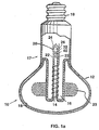
- FIG. 1 is an elevational broken-away and partly sectional view of a prior art electrodeless fluorescent lamp (fig. 1a) and a prior art compact fluorescent lamp (fig. 1b);
- FIG. 2 is a diagrammatic sectional illustration of an improved amalgam assembly for preventing movement of liquid amalgam into a lamp of the type shown in FIG. 1 from the preferred amalgam location; and
- FIG. 3 is similar to FIG. 2 but illustrative of an alternative embodiment.
- FIG. 4 is a perspective view of an improved retainer for preventing movement of liquid amalgam from the preferred amalgam location in a lamp of the type shown in FIG. 1;
- FIG. 5 is a diagrammatic illustration of the retainer of FIG. 4 disposed in an exhaust tubulation portion of a fluorescent lamp of the type shown in FIG. 1; and
- FIG. 6 is similar to FIG. 5, but illustrative of an alternative embodiment.
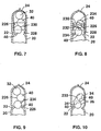
- FIG. 7 is a diagrammatic illustration of an improved amalgam assembly for preventing movement of liquid amalgam in a lamp of the type shown in FIG. 1 from the preferred amalgam location;
- FIG. 8 is similar to FIG. 7, but illustrative of the amalgam of FIG 7 after liquidizing thereof;
- FIG. 9 is similar to FIG. 7, but illustrative of an alternative embodiment of amalgam assembly; and
- FIG. 10 is similar to FIG. 9, but illustrative of the amalgam of FIG. 9 after liquidizing thereof.
-
- Referring to FIG. 1a it will be seen that a known base-up
compact fluorescent lamp 10 is provided with a light-transmissive envelope 12 containing an ionizable gaseous fill for sustaining an arc discharge. In manufacture, thelamp 10 is dosed with the fill via anexhaust tubulation 20 having aninside surface 26 in well-known manner. A suitable fill, for example, comprises a mixture of a rare gas (e.g., krypton and/or argon) and mercury vapor. This is an electrodeless configuration. Anexcitation coil 14 is situated within, and removable from, are-entrant cavity 16 within theenvelope 12. For purposes of illustration, thecoil 14 is shown schematically as being wound about theexhaust tubulation 20. However, thecoil 14 may be spaced apart from theexhaust tubulation 20 and wound about a core of insulating material (not shown), or may be free standing (not shown), as desired. The interior surfaces of theenvelope 12 are coated in well-known manner with asuitable phosphor 18. Theenvelope 12 fits into one end of abase assembly 17 containing a radio frequency power supply (not shown) with a standard (e.g., Edison type)lamp base 19. A similar concept of prior art showing al lamp with electrodes is shown in fig. 1b. - A
mercury amalgam body 32 is placed and retained in a location optimized for the particular amalgam in a particular lamp. Each amalgam has its own optimum range of operating temperatures to provide a suitable mercury vapor pressure. - A retaining means, for example an indentation, or dimple, 22 is situated toward a tip-off region of the
exhaust tubulation 20. The tip-off region is the area at the top of the exhaust tubulation which is sealed, or "tipped off" to form theclosed end 24 of the exhaust tubulation after evacuating and filling the lamp therethrough. - After the lamp is evacuated and filled through the
exhaust tubulation 20, an appropriately sized and shaped dose locating member, preferably comprising at least one (or several)glass ball 40, is inserted into theexhaust tubulation 20 through the opening at the tip-off region. By virtue of the presence of thedimple 22 and the size and shape ofglass ball 40, the dose locating member remains on the side of the dimple away from there-entrant cavity 16. Theamalgam 32 is then inserted into theexhaust tubulation 20 through the opening in the tip-off region. The combination ofdimple 22 andglass ball 40 results in placement and retention of theamalgam 32 at a predetermined location. As noted above, the exhaust tubulation is tipped-off above theamalgam 32 to provide the tubulation closedend 24. - In operation, current flows in the
coil 14 as a result of excitation by the radio frequency power supply. A radio frequency magnetic field is thereby established within theenvelope 12 which ionizes and excites the gaseous fill contained therein, resulting in atoroidal discharge 23 and emitting ultraviolet radiation therefrom. Thephosphor 18 absorbs the ultraviolet radiation and emits visible radiation. - Referring to FIG. 2, it will be seen that in accordance with the present invention there is provided an amalgam retaining structure comprising one or
more glass balls 40 disposed in theglass tubulation 20 and retained by at least onepinched portion 22 of the tubulation. Themercury amalgam body 32 is disposed between theglass balls 40 and the exhaust tubulation closedend 24, as shown in FIG. 2. - The
amalgam body 32 is generally spherically shaped, when in a solid state, and, in accordance with one embodiment of the invention, is provided with a lithium component. The lithium provides the amalgam, when liquidized, with the property of wetting theglass tubulation 20, especially theinside surface 26, and theglass balls 40. When the liquid amalgam is wetted to the glass, that is, adhered to the glass, the amalgam is prevented from flowing past theglass balls 40 disposed in thetubulation 20 and thereby prevented from entering thelamp envelope 12. - In accordance with an alternative embodiment of the invention, a
layer 34 of a metal alloy including a lithium component is coated on aninside surface 26 of the exhaust tubulation 20 (FIG. 3) between the tubulation closedend 24 and thepinched portion 22 of the tubulation, that is, in the area of theamalgam body 32. The presence of thelithium alloy layer 34 causes the amalgam, when liquidized, to wet, or adhere, to the lithium alloy layer, preventing the liquid amalgam from flowing past the retainingstructure 40 and into thelamp envelope 12. - In the embodiment shown in FIG. 3, the
metal layer 34 is adhered to the tubulation insidesurface 26 during manufacture of the tubulation. In operation of thelamp 10, the liquid amalgam adheres to thelayer 34, to prevent the amalgam from flowing by gravity into thelamp envelope 12. - It has been found, that in base-up lamps the glass ball type of locating
member 40 sometimes fails to retain liquidized amalgam in the upper region of the tubulation. As noted hereinabove, escape of the amalgam from the tubulation closed end region and into the envelope can lead to lamp failure. - Referring to FIG. 4, it will be seen that in accordance with a further embodiment of the present invention there is provided an amalgam retainer comprising a
metal cup 140 disposed in the glass tubulation 20 (FIG. 5) and retained by at least onepinched portion 22 of the tubulation. - The
cup 140 defines an annularouter wall 142 having afree edge 144 extending toward the tubulation closedend 24. Thecup 140 further defines a tubularcentral core portion 146 extending toward the tubulation closedend 24. Thecore portion 146 is provided with afree edge 147 which extends toward the tubulation closedend 24 further than the cup outer wallfree edge 144. Anannular trough 148 is formed by thecore portion 146 and theouter wall 142. - The
cup 140 is provided with a coating of metal wetting agent disposed on surfaces of thetrough 148 opposed to the tubulation closedend 24. Appropriate coatings to serve as wetting agents include silver and indium. Thecup 140 fits snugly in the tubulation and the peripheralouter walls 142 of thecup 140 engage the inner walls of the tubulation. Preferably, themetal cup 140 exhibits a leaf spring like quality, thewalls 142 being thereby biased into engagement with the tubulation inner walls. Stainless steel and iron-nickel alloys have been found to be suitable materials for thecup 140. - The
mercury amalgam body 32 is disposed between themetal cup 140 and the exhaust tubulation closedend 24, as shown in FIG. 5. Theamalgam body 32 is generally spherically shaped and provided with a diameter exceeding the inside diameter of thecore portion 146 of thecup 140. - When the lamp is completed and placed in operation, the
amalgam body 32 liquidizes and is attracted to thecup trough 148 by the wetting agent therein. Thus, the liquid amalgam occupies the trough in an annular arrangement, while mercury vapor is allowed to pass through the cup core portion. - Referring to FIG. 6, it will be seen that the
metal cup 140 may be used in combination with one ormore glass balls 40, such that theglass ball 40 serves its usual function of retaining the liquid amalgam but is, in effect, "backed up" by themetal cup 140 which attracts and retains any amalgam that gets by the glass ball.
Referring once again to FIG. 1, it has been found that the while the combination of tubulation pinchedportion 22 andglass balls 40 serves to retain the amalgam at the closed end of the tubulation most of the time, there are occasions when the liquid amalgam finds its way around the glass balls and into the lamp envelope, causing malfunction and/or failure of the lamp. - In accordance with a further embodiment of the invention, a
layer 226 of a metallic mercury wetting agent is disposed on aninside surface 228 of thetubulation 20 in an area between thepinched portion 22 and theclosed end 24 of the tubulation. Thewetting agent layer 226 may be of indium or silver or gold, or alloys having at least one of such metals as a component thereof. Thewetting agent layer 226 may be disposed in aband 230, as shown in FIG. 7. - When the
amalgam body 32 in a base-up lamp is liquidized, the liquid amalgam tends to flow downwardly and, on occasion flows around the glass body orbodies 40 resulting inpatches 232 on thesurface 234 of thebodies 40 and into thelamp envelope 12. However, with the wetting agent band 30 in place, the liquid amalgam is attracted to, and adheres to, the band 30 (FIG. 8) and is thereby prevented from moving further towards thelamp envelope 12. - Referring to FIG. 9, it will be seen that in an alternative embodiment the metallic mercury wetting agent is disposed on the
surface 234 of the glass body orbodies 40 disposed in thetubulation 20. When the amalgam liquidizies, it is attracted to theglass bodies 40 and as anunstructered cluster 233 attaches thereto (FIG. 10), rather than flowing around the glass bodies and toward the lamp envelope. - It will be understood that many additional changes in the details, materials, and arrangement of parts, which have been herein described and illustrated in order to explain the nature of the invention, may be made by those skilled in the art within the principles and scope of the invention as expressed in the appended claims.
Claims (49)
- An amalgam assembly for a mercury low-pressure lamp, preferably a fluorescent lamp, the assembly comprising:characterized in:a glass exhaust tubulation being connected to an envelope portion of the lamp, said tubulation being closed at one end thereof; and having an opening into the interior of the envelope;a retaining structure disposed in said tubulation; anda mercury amalgam body disposed in said tubulation between said retaining structure and the tubulation closed end,said amalgam assembly comprising a means for wetting internal surfaces within said glass tubulation to cause said amalgam to adhere to said tubulation internal surfaces when said amalgam body is liquidized and to thereby prevent said amalgam from flowing past said retaining structure and into the interior of the envelope.
- An amalgam assembly for a fluorescent lamp in accordance with claim 1, wherein said mercury amalgam body (32), which is disposed in said tubulation (20) between said retaining structure (22) and the tubulation closed end (24), is including lithium for wetting internal surfaces of said glass tubulation to cause said amalgam to adhere to the tubulation internal surfaces when said amalgam body is liquidized and to thereby prevent said amalgam from flowing past said retaining structure and into the lamp envelope.
- The amalgam assembly in accordance with claim 2 wherein said amalgam body comprises an alloy composition selected from a group of alloy compositions consisting of (i) bismuth and indium and lithium, (ii) bismuth and tin and lead and lithium, (iii) bismuth and tin and lithium, (iv) zinc and indium and tin and lithium, (v) indium and lithium, (vi) lead and lithium, and (vii) zinc and lithium.
- The amalgam assembly in accordance with claim 2 wherein said retaining structure comprises at least one glass body, and wherein the lithium causes said amalgam to wet the glass body to cause the amalgam to adhere further to the glass body when said amalgam body is liquidized, to further prevent said amalgam from flowing into the lamp envelope.
- The amalgam assembly in accordance with claim 1 wherein said amalgam body is spherically or cylindrically shaped when in a solid state.
- The amalgam assembly in accordance with claim 1 wherein said retaining structure comprises a pinched portion (22) of said tubulation
- The amalgam assembly in accordance with claim 1 wherein said wetting means is a layer of metal containing lithium adhered to an inside surface of said exhaust tubulation between the tubulation closed end and the retaining structure;
wherein upon liquidizing of said amalgam body, the liquid amalgam adheres to said layer, to thereby prevent the amalgam from flowing past the retaining structure and into the lamp envelope. - The amalgam assembly in accordance with claim 7, further comprising a retaining member disposed in said tubulation between a tubulation pinched portion as retaining structure and said amalgam body.
- The amalgam assembly in accordance with claim 8 wherein said retaining member comprises a glass body or a metal body, which is preferably spherically shaped.
- The amalgam assembly in accordance with claim 1, wherein said wetting means is a two-part structure, with a metal cup being disposed, as a first part of said wetting means, in said tubulation and retained by said retaining structure of said tubulation, said cup defining a trough open towards the tubulation closed end and an aperture extending through said cup; wherein said mercury amalgam body is disposed in said tubulation between said metal cup and the tubulation closed end; and a coating of a metal wetting agent, as a second part of said wetting means, is disposed on surfaces of the trough opposed to the tubulation closed end;
whereby when said amalgam body liquidizes, the liquid amalgam adheres to the cup trough surfaces and mercury vapor is flowable through the cup aperture. - The amalgam assembly in accordance with claim 10 wherein said metal cup snugly fits in said tubulation and peripheral walls of said cup are engaged with interior walls of said tubulation.
- The amalgam assembly in accordance with claim 11 wherein said cup is of a metal having sufficient springiness to bias the cup peripheral walls against the interior walls of the tubulation.
- The amalgam assembly in accordance with claim 12 wherein said cup is of a metal selected from (i) stainless steel and (ii) iron-nickel alloy.
- The amalgam assembly in accordance with claim 10 wherein said cup trough comprises an annular trough defined by a cup outer wall having a free edge extending toward the tubulation closed end, and by a cup tubular central core portion defining the aperture and extending toward the tubulation closed end.
- The amalgam assembly in accordance with claim 10 wherein said amalgam body is generally spherically shaped and is provided with a diameter exceeding an inner diameter of the core portion aperture.
- The amalgam assembly in accordance with claim 10 wherein the metal wetting agent comprises a selected one of (i) silver and (ii) indium.
- The amalgam assembly in accordance with claim 14 wherein said cup core portion extends closer to the tubulation closed end than does the cup outer wall.
- The amalgam assembly in accordance with claim 10, said assembly comprising a metal cup disposed in said tubulation and retained by a pinched portion of said tubulation, said cup defining an annular outer wall having a free edge extending toward the tubulation closed end, a tubular central core portion extending toward the tubulation closed end, and an annular trough formed by said core portion and the outer wall;a mercury amalgam ball disposed between said metal cup and the tubulation closed end, a diameter of said ball exceeding an inner diameter of said core portion; anda coating of a metal wetting agent disposed on interior surfaces of said trough;whereby when said amalgam body liquidizes, the liquid amalgam adheres to the wetting agent in the cup trough and mercury vapor is flowable through the cup core portion.
- The amalgam assembly in accordance with claim 10 and further comprising a glass ball disposed in said tubulation between said metal cup and the tubulation closed end.
- The amalgam assembly in accordance with claim 1, further comprising a glass body disposed in said tubulation and retained by said retaining structure, pref. a pinched portion of said tubulation, said glass body being disposed between said retaining structure of said tubulation and the closed end of said tubulation;whereby to wet at least one of (i) an interior surface of said glass tubulation and (ii) the surface of said glass body, to prevent liquid amalgam from flowing past the tubulation pinched portion and into the lamp envelope.said mercury amalgam body disposed between the glass body and the closed end of said tubulation; anda mercury wetting metallic layer disposed, as a wetting means, on a selected one of (i) an inside surface of said tubulation between the pinched portion and the closed end of said tubulation, and (ii) a surface of said glass body;
- The amalgam assembly in accordance with claim 20 wherein said mercury wetting metallic layer is of a selected one of silver, gold, and indium, and alloys thereof, respectively.
- The amalgam assembly in accordance with claim 20 wherein said amalgam body is generally spheroid in configuration prior to liquidizing thereof and wherein said glass body is of a spheroid configuration, and further comprising a second glass spheroid disposed between the reatining strucuture, pref. a pinched portion, of said tubulation and said amalgam body, said second glass spheroid obstructing movement of said amalgam body in the tubulation past the second glass spheroid when said amalgam body is in a solid state.
- The amalgam assembly in accordance with claim 20 wherein said mercury wetting metallic layer is disposed on the inside surface of said tubulation and upon liquidizing of said amalgam body the liquid amalgam adheres to an inside surface of said tubulation in an area of said metallic layer.
- The amalgam assembly in accordance with claim 20 wherein said mercury wetting metallic layer is disposed on the surface of the glass body and upon liquidizing of said amalgam body the liquid amalgam adheres to the surface of the glass body.
- A fluorescent lamp with an amalgam assembly in accordance with one of the previous claims.
- An electrodeless fluorescent lamp assembly, comprising:a light-transmissive envelope containing an ionizable, gaseous fill for sustaining an arc discharge when subjected to a radio frequency magnetic field and for emitting ultraviolet radiation as a result thereof, said envelope having an interior phosphor coating for emitting visible radiation when excited by the ultraviolet radiation, said envelope having a re-entrant cavity formed therein;an excitation coil contained within the re-entrant cavity for providing the radio frequency magnetic field when excited by a radio frequency power supply;a glass exhaust tubulation extending through the re-entrant cavity and into said envelope, said exhaust tubulation having a closed end proximate a base portion of the lamp;a pinched configuration formed in said exhaust tubulation at a predetermined distance from the tubulation closed end;a retaining structure disposed in said tubulation and retained by said pinched configuration; anda mercury amalgam body disposed in said tubulation between said retaining structure and the tubulation closed end, said amalgam body including lithium for wetting internal surfaces of said glass tubulation to cause said amalgam to adhere to the tubulation internal surfaces when said amalgam body is liquidized and to thereby prevent the amalgam from flowing past said retaining structure and into the lamp envelope.
- The lamp assembly in accordance with claim 26 wherein said amalgam body comprises an alloy composition selected from a group of alloy compositions consisting of (i) bismuth and indium and lithium, (ii) bismuth and tin and lead and lithium, (iii) bismuth and tin and lithium, (iv) zinc and indium and tin and lithium, (v) indium and lithium, (vi) lead and lithium, and (vii) zinc and lithium.
- The lamp assembly in accordance with claim 26, wherein said retaining structure comprises a glass body, and wherein the lithium is adapted to wet the glass body to cause the amalgam to adhere further to the glass body when said amalgam body is liquidized, to further prevent the amalgam from flowing past the glass body and into the lamp.
- The lamp assembly in accordance with claim 26 wherein said amalgam body is spherically shaped when in a solid state.
- The lamp assembly in accordance with claim 26 wherein said retaining structure comprises a glass body.
- The lamp assembly in accordance with claim 30 wherein the glass body is spherically shaped.
- An electrodeless fluorescent lamp assembly, comprising:wherein upon liquidizing of said amalgam body, the liquid amalgam adheres to said layer, to thereby prevent the amalgam from flowing past said retaining structure and into the lamp envelope.a light-transmissive envelope containing an ionizable, gaseous fill for sustaining an arc discharge when subjected to a radio frequency magnetic field and for emitting ultraviolet radiation as a result thereof, said envelope having an interior phosphor coating for emitting visible radiation when excited by the ultraviolet radiation, said envelope having a re-entrant cavity formed therein;an excitation coil contained within the re-entrant cavity for providing the radio frequency magnetic field when excited by a radio frequency power supply;a glass exhaust tubulation extending through the re-entrant cavity and into said envelope, said exhaust tubulation having a closed end proximate a base portion of the lamp;a pinched configuration formed in said exhaust tubulation at a predetermined distance from the tubulation closed end;a retaining structure disposed in said tubulation and retained by said pinched configuration;a mercury amalgam body disposed in said tubulation between said retaining structure and tubulation closed end; anda layer of metal containing lithium adhered to an inside surface of said exhaust tubulation between the tubulation closed end and said tubulation pinched configuration;
- The lamp assembly in accordance with claim 32 wherein said amalgam body comprises an alloy composition selected from a group of alloy compositions consisting of (i) bismuth and indium and lithium, (ii) bismuth and tin and lead and lithium, (iii) bismuth and tin and lithium, (iv) zinc and indium and tin and lithium, (v) indium and lithium, (vi) lead and lithium, and (vii) zinc and lithium.
- The lamp assembly in accordance with claim 32 wherein said retaining structure comprises a glass body, and wherein the layer of metal is adapted to wet the glass body to cause the amalgam to adhere further to the glass body when said amalgam body is liquidized, to further prevent the amalgam from flowing into the lamp envelope.
- The lamp assembly in accordance with claim 34 wherein the glass body is spherically shaped.
- An electrodeless fluorescent lamp, comprising:a light-transmissive envelope containing an ionizable, gaseous fill for sustaining an arc discharge when subjected to a radio frequency magnetic field and for emitting ultraviolet radiation as a result thereof, said envelope having an interior phosphor coating for emitting visible radiation when excited by the ultraviolet radiation, said envelope having a re-entrant cavity formed therein;an excitation coil contained within the re-entrant cavity for providing the radio frequency magnetic field when excited by a radio frequency power supply;an exhaust tubulation extending through the re-entrant cavity and into said envelope for evacuating and filling said lamp, said exhaust tubulation having a closed end proximate a base portion of the lamp;a dimple configuration formed in said exhaust tubulation at a predetermined distance from the tubulation closed end;a mercury amalgam body disposed in said tubulation;a metal cup for retaining said amalgam body in a location in said exhaust tubulation between said metal cup and the closed end of said exhaust tubulation, said metal cup defining an annular wall having a free edge extending toward the exhaust tubulation closed end, a tubular central core portion extending toward the exhaust tubulation closed end, and an annular trough formed by the core portion and the outer wall; anda coating of a metal wetting agent disposed on interior surfaces of the trough;whereby when said amalgam body liquidizes, the liquid amalgam adheres to the cup trough surfaces, and mercury vapor is flowable through the cup core portion.
- The lamp in accordance with claim 36 wherein said metal cup snugly fits in said tubulation and peripheral walls of said cup are engaged with interior walls of said tubulation.
- The lamp in accordance with claim 37 wherein said cup is of a metal having sufficient springiness to bias the cup peripheral walls against the interior walls of the tubulation.
- The lamp in accordance with claim 38 wherein said cup is of a metal selected from (i) stainless steel and (ii) iron-nickel alloy.
- The lamp in accordance with claim 36 wherein the metal wetting agent comprises a selected one of (i) silver and (ii) indium.
- The lamp in accordance with claim 36 wherein said cup core portion extends closer to the tubulation distal end than the cup outer wall.
- The lamp in accordance with claim 36 and further comprising a glass ball disposed in said exhaust tubulation between said metal cup and the closed end of said exhaust tubulation.
- An electrodeless fluorescent lamp assembly, comprising:a light-transmissive envelope containing an ionizable, gaseous fill for sustaining an arc discharge when subjected to a radio frequency magnetic field and for emitting ultraviolet radiation as a result thereof, said envelope having an interior phosphor coating for emitting visible radiation when excited by the ultraviolet radiation, said envelope having a re-entrant cavity formed therein;an excitation coil contained within the re-entrant cavity for providing the radio frequency magnetic field when excited by a radio frequency power supply;an exhaust tubulation extending through the re-entrant cavity and into said envelope, said exhaust tubulation having a closed end proximate a base portion of the lamp;a pinched portion formed in said exhaust tubulation at a selected distance from said closed end;a mercury amalgam body disposed in said exhaust tubulation between the exhaust tubulation closed end and said pinched portion of said exhaust tubulation;a glass body disposed in said exhaust tubulation and retained by said pinched portion, said glass body being disposed between said pinched portion of said tubulation and said amalgam body; anda coating of a metal wetting agent disposed on a selected one of (i) an inside surface of said tubulation between said pinched portion and the closed end of said tubulation, and (ii) a surface of said glass body;whereby to wet at least one of (i) the interior surface of said glass tubulation, and (ii) the surface of said glass body, to prevent said amalgam from flowing past the tubulation pinched portion into the lamp envelope.
- The lamp assembly in accordance with claim 43 wherein said mercury wetting metallic layer is of a selected one of silver, gold, and indium, and alloys thereof, respectively.
- The lamp in accordance with claim 43 wherein said amalgam body is generally spheroid in configuration prior to liquidizing thereof.
- The lamp assembly in accordance with claim 43 wherein said glass body is of a spheroid configuration.
- The lamp assembly in accordance with claim 46 and further comprising a second glass spheroid disposed between said pinched portion of said tubulation and said amalgam body, said second glass spheroid obstructing movement of said amalgam body in said tubulation past the tubulation pinched portion when said amalgam is in a solid state.
- The lamp assembly in accordance with claim 43 wherein said mercury wetting metallic layer is disposed on the inside surface of said tubulation and upon liquidizing of said amalgam body the liquid amalgam adheres to the inside surface of said tubulation in an area of said metallic layer.
- The lamp assembly in accordance with claim 43 wherein said mercury wetting metallic layer is disposed on the surface of the glass body and upon liquidizing of said amalgam body the liquid amalgam adheres to the surface of the glass body.
Applications Claiming Priority (6)
| Application Number | Priority Date | Filing Date | Title |
|---|---|---|---|
| US10/225,718 US6650041B1 (en) | 2002-08-22 | 2002-08-22 | Fluorescent lamp and amalgam assembly therefor |
| US225718 | 2002-08-22 | ||
| US226556 | 2002-08-23 | ||
| US10/226,556 US6653775B1 (en) | 2002-08-23 | 2002-08-23 | Fluorescent lamp and amalgam assembly therefor |
| US10/230,621 US6784609B2 (en) | 2002-08-29 | 2002-08-29 | Fluorescent lamp and amalgam assembly therefor |
| US230621 | 2002-08-29 |
Publications (2)
| Publication Number | Publication Date |
|---|---|
| EP1391913A1 true EP1391913A1 (en) | 2004-02-25 |
| EP1391913B1 EP1391913B1 (en) | 2008-03-12 |
Family
ID=31192013
Family Applications (1)
| Application Number | Title | Priority Date | Filing Date |
|---|---|---|---|
| EP03016255A Expired - Lifetime EP1391913B1 (en) | 2002-08-22 | 2003-07-17 | Fluorescent lamp and amalgam assembly therefor |
Country Status (6)
| Country | Link |
|---|---|
| EP (1) | EP1391913B1 (en) |
| JP (1) | JP4388770B2 (en) |
| KR (1) | KR101036746B1 (en) |
| CN (1) | CN100334680C (en) |
| AT (1) | ATE389236T1 (en) |
| DE (1) | DE60319640T2 (en) |
Families Citing this family (5)
| Publication number | Priority date | Publication date | Assignee | Title |
|---|---|---|---|---|
| JP5174148B2 (en) * | 2007-05-09 | 2013-04-03 | コーニンクレッカ フィリップス エレクトロニクス エヌ ヴィ | Low pressure mercury discharge lamp with amalgam capsule with amalgam chamber |
| CN101826443A (en) * | 2009-03-06 | 2010-09-08 | 李博 | Electrodeless fluorescent lamp bulb |
| KR101201279B1 (en) * | 2010-12-03 | 2012-11-15 | 에프엔에스테크 주식회사 | Mercury discharge lamp using amalgam |
| KR101868523B1 (en) * | 2017-11-27 | 2018-06-19 | 김태화 | Ultraviolet lamp and manufacturing method thereof |
| KR101876178B1 (en) * | 2017-11-27 | 2018-07-09 | 장명옥 | Apparatus for advanced oxidation process |
Citations (5)
| Publication number | Priority date | Publication date | Assignee | Title |
|---|---|---|---|---|
| US4288715A (en) * | 1978-10-11 | 1981-09-08 | U.S. Philips Corporation | Low-pressure mercury vapor discharge lamp |
| US5294867A (en) * | 1992-03-13 | 1994-03-15 | Gte Products Corporation | Low pressure mercury vapor discharge lamp containing an amalgam |
| US5629584A (en) * | 1993-10-04 | 1997-05-13 | General Electric Company | Accurate placement and retention of an amalgam in a electrodeless fluorescent lamp |
| US5757129A (en) * | 1995-03-31 | 1998-05-26 | Patent-Treuhand-Gesellschaft Fuer Elektrische Gluehlampen Mbh | Low-pressure mercury-vapor discharge lamp, and method of placing mercury therein |
| JPH11185704A (en) * | 1997-12-19 | 1999-07-09 | Osram Melco Kk | Fluorescent lamp device |
Family Cites Families (5)
| Publication number | Priority date | Publication date | Assignee | Title |
|---|---|---|---|---|
| JPH01186544A (en) * | 1988-01-13 | 1989-07-26 | Toshiba Corp | Amalgam-sealed type fluorescent lamp |
| US5434482A (en) * | 1993-10-04 | 1995-07-18 | General Electric Company | Electrodeless fluorescent lamp with optimized amalgam positioning |
| TW344084B (en) * | 1995-05-24 | 1998-11-01 | Philips Eloctronics N V | Lighting unit, electrodeless low-pressure discharge lamp, and discharge vessel for use in the lighting unit |
| GB9521375D0 (en) | 1995-10-18 | 1995-12-20 | Gen Electric | Electrodeless fluorescent lamp |
| GB9603197D0 (en) * | 1996-02-15 | 1996-04-17 | Gen Electric | Electrodeless discharge lamp |
-
2003
- 2003-07-17 DE DE60319640T patent/DE60319640T2/en not_active Expired - Lifetime
- 2003-07-17 AT AT03016255T patent/ATE389236T1/en not_active IP Right Cessation
- 2003-07-17 EP EP03016255A patent/EP1391913B1/en not_active Expired - Lifetime
- 2003-08-19 KR KR1020030057165A patent/KR101036746B1/en not_active Expired - Fee Related
- 2003-08-21 JP JP2003208304A patent/JP4388770B2/en not_active Expired - Fee Related
- 2003-08-22 CN CNB031546498A patent/CN100334680C/en not_active Expired - Fee Related
Patent Citations (5)
| Publication number | Priority date | Publication date | Assignee | Title |
|---|---|---|---|---|
| US4288715A (en) * | 1978-10-11 | 1981-09-08 | U.S. Philips Corporation | Low-pressure mercury vapor discharge lamp |
| US5294867A (en) * | 1992-03-13 | 1994-03-15 | Gte Products Corporation | Low pressure mercury vapor discharge lamp containing an amalgam |
| US5629584A (en) * | 1993-10-04 | 1997-05-13 | General Electric Company | Accurate placement and retention of an amalgam in a electrodeless fluorescent lamp |
| US5757129A (en) * | 1995-03-31 | 1998-05-26 | Patent-Treuhand-Gesellschaft Fuer Elektrische Gluehlampen Mbh | Low-pressure mercury-vapor discharge lamp, and method of placing mercury therein |
| JPH11185704A (en) * | 1997-12-19 | 1999-07-09 | Osram Melco Kk | Fluorescent lamp device |
Non-Patent Citations (1)
| Title |
|---|
| PATENT ABSTRACTS OF JAPAN vol. 1999, no. 12 29 October 1999 (1999-10-29) * |
Also Published As
| Publication number | Publication date |
|---|---|
| JP4388770B2 (en) | 2009-12-24 |
| CN100334680C (en) | 2007-08-29 |
| ATE389236T1 (en) | 2008-03-15 |
| DE60319640D1 (en) | 2008-04-24 |
| EP1391913B1 (en) | 2008-03-12 |
| KR101036746B1 (en) | 2011-05-24 |
| KR20040018149A (en) | 2004-03-02 |
| JP2004087484A (en) | 2004-03-18 |
| DE60319640T2 (en) | 2009-04-02 |
| CN1495846A (en) | 2004-05-12 |
Similar Documents
| Publication | Publication Date | Title |
|---|---|---|
| US5434482A (en) | Electrodeless fluorescent lamp with optimized amalgam positioning | |
| EP0646942B1 (en) | Accurate placement and retention of an amalgam in an electrodeless fluorescent lamp | |
| US5412289A (en) | Using a magnetic field to locate an amalgam in an electrodeless fluorescent lamp | |
| JPS6221223B2 (en) | ||
| WO1993018542A1 (en) | Low pressure mercury vapor discharge lamp containing an amalgam | |
| US20040056583A1 (en) | Fluorescent lamp and amalgam assembly therefor | |
| US6650041B1 (en) | Fluorescent lamp and amalgam assembly therefor | |
| US5559392A (en) | Apparatus for securing an amalgam at the apex of an electrodeless fluorescent lamp | |
| US5847508A (en) | Integrated starting and running amalgam assembly for an electrodeless fluorescent lamp | |
| US6653775B1 (en) | Fluorescent lamp and amalgam assembly therefor | |
| US6784609B2 (en) | Fluorescent lamp and amalgam assembly therefor | |
| EP1391913B1 (en) | Fluorescent lamp and amalgam assembly therefor | |
| US4528209A (en) | Use of amalgams in solenoidal electric field lamps | |
| US6913504B2 (en) | Method for introducing mercury into a fluorescent lamp during manufacture and a mercury carrier body facilitating such method | |
| US6905385B2 (en) | Method for introducing mercury into a fluorescent lamp during manufacture and a mercury carrier body facilitating such method | |
| JP2005346983A (en) | Electrodeless discharge lamp and its manufacturing method | |
| CA2455361C (en) | Method for introducing mercury into a fluorescent lamp during manufacture and a mercury carrier body facilitating such method | |
| JP3424331B2 (en) | Mercury vapor discharge lamp, method of manufacturing this lamp, and lighting device | |
| JP2004288385A (en) | Electrodeless fluorescent lamp, electrodeless fluorescent lamp and lighting equipment | |
| JP2003077417A (en) | Low pressure mercury vapor discharge lamp and lighting equipment |
Legal Events
| Date | Code | Title | Description |
|---|---|---|---|
| PUAI | Public reference made under article 153(3) epc to a published international application that has entered the european phase |
Free format text: ORIGINAL CODE: 0009012 |
|
| AK | Designated contracting states |
Kind code of ref document: A1 Designated state(s): AT BE BG CH CY CZ DE DK EE ES FI FR GB GR HU IE IT LI LU MC NL PT RO SE SI SK TR |
|
| AX | Request for extension of the european patent |
Extension state: AL LT LV MK |
|
| 17P | Request for examination filed |
Effective date: 20040322 |
|
| AKX | Designation fees paid |
Designated state(s): AT BE BG CH CY CZ DE DK EE ES FI FR GB GR HU IE IT LI LU MC NL PT RO SE SI SK TR |
|
| 17Q | First examination report despatched |
Effective date: 20060810 |
|
| GRAP | Despatch of communication of intention to grant a patent |
Free format text: ORIGINAL CODE: EPIDOSNIGR1 |
|
| GRAS | Grant fee paid |
Free format text: ORIGINAL CODE: EPIDOSNIGR3 |
|
| GRAA | (expected) grant |
Free format text: ORIGINAL CODE: 0009210 |
|
| AK | Designated contracting states |
Kind code of ref document: B1 Designated state(s): AT BE BG CH CY CZ DE DK EE ES FI FR GB GR HU IE IT LI LU MC NL PT RO SE SI SK TR |
|
| REG | Reference to a national code |
Ref country code: GB Ref legal event code: FG4D |
|
| REG | Reference to a national code |
Ref country code: CH Ref legal event code: EP |
|
| REG | Reference to a national code |
Ref country code: IE Ref legal event code: FG4D |
|
| REF | Corresponds to: |
Ref document number: 60319640 Country of ref document: DE Date of ref document: 20080424 Kind code of ref document: P |
|
| PG25 | Lapsed in a contracting state [announced via postgrant information from national office to epo] |
Ref country code: FI Free format text: LAPSE BECAUSE OF FAILURE TO SUBMIT A TRANSLATION OF THE DESCRIPTION OR TO PAY THE FEE WITHIN THE PRESCRIBED TIME-LIMIT Effective date: 20080312 |
|
| PG25 | Lapsed in a contracting state [announced via postgrant information from national office to epo] |
Ref country code: AT Free format text: LAPSE BECAUSE OF FAILURE TO SUBMIT A TRANSLATION OF THE DESCRIPTION OR TO PAY THE FEE WITHIN THE PRESCRIBED TIME-LIMIT Effective date: 20080312 |
|
| ET | Fr: translation filed | ||
| REG | Reference to a national code |
Ref country code: HU Ref legal event code: AG4A Ref document number: E003483 Country of ref document: HU |
|
| PG25 | Lapsed in a contracting state [announced via postgrant information from national office to epo] |
Ref country code: SI Free format text: LAPSE BECAUSE OF FAILURE TO SUBMIT A TRANSLATION OF THE DESCRIPTION OR TO PAY THE FEE WITHIN THE PRESCRIBED TIME-LIMIT Effective date: 20080312 |
|
| PG25 | Lapsed in a contracting state [announced via postgrant information from national office to epo] |
Ref country code: SK Free format text: LAPSE BECAUSE OF FAILURE TO SUBMIT A TRANSLATION OF THE DESCRIPTION OR TO PAY THE FEE WITHIN THE PRESCRIBED TIME-LIMIT Effective date: 20080312 Ref country code: SE Free format text: LAPSE BECAUSE OF FAILURE TO SUBMIT A TRANSLATION OF THE DESCRIPTION OR TO PAY THE FEE WITHIN THE PRESCRIBED TIME-LIMIT Effective date: 20080612 Ref country code: CZ Free format text: LAPSE BECAUSE OF FAILURE TO SUBMIT A TRANSLATION OF THE DESCRIPTION OR TO PAY THE FEE WITHIN THE PRESCRIBED TIME-LIMIT Effective date: 20080312 Ref country code: ES Free format text: LAPSE BECAUSE OF FAILURE TO SUBMIT A TRANSLATION OF THE DESCRIPTION OR TO PAY THE FEE WITHIN THE PRESCRIBED TIME-LIMIT Effective date: 20080623 Ref country code: PT Free format text: LAPSE BECAUSE OF FAILURE TO SUBMIT A TRANSLATION OF THE DESCRIPTION OR TO PAY THE FEE WITHIN THE PRESCRIBED TIME-LIMIT Effective date: 20080818 |
|
| PG25 | Lapsed in a contracting state [announced via postgrant information from national office to epo] |
Ref country code: RO Free format text: LAPSE BECAUSE OF FAILURE TO SUBMIT A TRANSLATION OF THE DESCRIPTION OR TO PAY THE FEE WITHIN THE PRESCRIBED TIME-LIMIT Effective date: 20080312 |
|
| PLBE | No opposition filed within time limit |
Free format text: ORIGINAL CODE: 0009261 |
|
| STAA | Information on the status of an ep patent application or granted ep patent |
Free format text: STATUS: NO OPPOSITION FILED WITHIN TIME LIMIT |
|
| PG25 | Lapsed in a contracting state [announced via postgrant information from national office to epo] |
Ref country code: DK Free format text: LAPSE BECAUSE OF FAILURE TO SUBMIT A TRANSLATION OF THE DESCRIPTION OR TO PAY THE FEE WITHIN THE PRESCRIBED TIME-LIMIT Effective date: 20080312 |
|
| 26N | No opposition filed |
Effective date: 20081215 |
|
| REG | Reference to a national code |
Ref country code: CH Ref legal event code: PL |
|
| PG25 | Lapsed in a contracting state [announced via postgrant information from national office to epo] |
Ref country code: MC Free format text: LAPSE BECAUSE OF NON-PAYMENT OF DUE FEES Effective date: 20080731 |
|
| PG25 | Lapsed in a contracting state [announced via postgrant information from national office to epo] |
Ref country code: BG Free format text: LAPSE BECAUSE OF FAILURE TO SUBMIT A TRANSLATION OF THE DESCRIPTION OR TO PAY THE FEE WITHIN THE PRESCRIBED TIME-LIMIT Effective date: 20080612 Ref country code: EE Free format text: LAPSE BECAUSE OF FAILURE TO SUBMIT A TRANSLATION OF THE DESCRIPTION OR TO PAY THE FEE WITHIN THE PRESCRIBED TIME-LIMIT Effective date: 20080312 |
|
| PG25 | Lapsed in a contracting state [announced via postgrant information from national office to epo] |
Ref country code: LI Free format text: LAPSE BECAUSE OF NON-PAYMENT OF DUE FEES Effective date: 20080731 Ref country code: CH Free format text: LAPSE BECAUSE OF NON-PAYMENT OF DUE FEES Effective date: 20080731 |
|
| PG25 | Lapsed in a contracting state [announced via postgrant information from national office to epo] |
Ref country code: IE Free format text: LAPSE BECAUSE OF NON-PAYMENT OF DUE FEES Effective date: 20080717 |
|
| PG25 | Lapsed in a contracting state [announced via postgrant information from national office to epo] |
Ref country code: CY Free format text: LAPSE BECAUSE OF FAILURE TO SUBMIT A TRANSLATION OF THE DESCRIPTION OR TO PAY THE FEE WITHIN THE PRESCRIBED TIME-LIMIT Effective date: 20080312 |
|
| PG25 | Lapsed in a contracting state [announced via postgrant information from national office to epo] |
Ref country code: LU Free format text: LAPSE BECAUSE OF NON-PAYMENT OF DUE FEES Effective date: 20080717 |
|
| PG25 | Lapsed in a contracting state [announced via postgrant information from national office to epo] |
Ref country code: TR Free format text: LAPSE BECAUSE OF FAILURE TO SUBMIT A TRANSLATION OF THE DESCRIPTION OR TO PAY THE FEE WITHIN THE PRESCRIBED TIME-LIMIT Effective date: 20080312 |
|
| PG25 | Lapsed in a contracting state [announced via postgrant information from national office to epo] |
Ref country code: GR Free format text: LAPSE BECAUSE OF FAILURE TO SUBMIT A TRANSLATION OF THE DESCRIPTION OR TO PAY THE FEE WITHIN THE PRESCRIBED TIME-LIMIT Effective date: 20080613 |
|
| PGFP | Annual fee paid to national office [announced via postgrant information from national office to epo] |
Ref country code: BE Payment date: 20130719 Year of fee payment: 11 Ref country code: NL Payment date: 20130719 Year of fee payment: 11 Ref country code: DE Payment date: 20130722 Year of fee payment: 11 Ref country code: HU Payment date: 20130719 Year of fee payment: 11 |
|
| PGFP | Annual fee paid to national office [announced via postgrant information from national office to epo] |
Ref country code: FR Payment date: 20130722 Year of fee payment: 11 Ref country code: GB Payment date: 20130719 Year of fee payment: 11 |
|
| PGFP | Annual fee paid to national office [announced via postgrant information from national office to epo] |
Ref country code: IT Payment date: 20130730 Year of fee payment: 11 |
|
| REG | Reference to a national code |
Ref country code: DE Ref legal event code: R119 Ref document number: 60319640 Country of ref document: DE |
|
| REG | Reference to a national code |
Ref country code: NL Ref legal event code: V1 Effective date: 20150201 |
|
| GBPC | Gb: european patent ceased through non-payment of renewal fee |
Effective date: 20140717 |
|
| PG25 | Lapsed in a contracting state [announced via postgrant information from national office to epo] |
Ref country code: NL Free format text: LAPSE BECAUSE OF NON-PAYMENT OF DUE FEES Effective date: 20150201 |
|
| REG | Reference to a national code |
Ref country code: FR Ref legal event code: ST Effective date: 20150331 |
|
| PG25 | Lapsed in a contracting state [announced via postgrant information from national office to epo] |
Ref country code: IT Free format text: LAPSE BECAUSE OF NON-PAYMENT OF DUE FEES Effective date: 20140717 Ref country code: DE Free format text: LAPSE BECAUSE OF NON-PAYMENT OF DUE FEES Effective date: 20150203 Ref country code: HU Free format text: LAPSE BECAUSE OF NON-PAYMENT OF DUE FEES Effective date: 20140718 |
|
| REG | Reference to a national code |
Ref country code: DE Ref legal event code: R119 Ref document number: 60319640 Country of ref document: DE Effective date: 20150203 |
|
| PG25 | Lapsed in a contracting state [announced via postgrant information from national office to epo] |
Ref country code: FR Free format text: LAPSE BECAUSE OF NON-PAYMENT OF DUE FEES Effective date: 20140731 Ref country code: GB Free format text: LAPSE BECAUSE OF NON-PAYMENT OF DUE FEES Effective date: 20140717 |
|
| PG25 | Lapsed in a contracting state [announced via postgrant information from national office to epo] |
Ref country code: BE Free format text: LAPSE BECAUSE OF NON-PAYMENT OF DUE FEES Effective date: 20140731 |