EP1391910A2 - Crt having a contrast enhancing exterior coating and method of manufacturing the same - Google Patents
Crt having a contrast enhancing exterior coating and method of manufacturing the same Download PDFInfo
- Publication number
- EP1391910A2 EP1391910A2 EP03102372A EP03102372A EP1391910A2 EP 1391910 A2 EP1391910 A2 EP 1391910A2 EP 03102372 A EP03102372 A EP 03102372A EP 03102372 A EP03102372 A EP 03102372A EP 1391910 A2 EP1391910 A2 EP 1391910A2
- Authority
- EP
- European Patent Office
- Prior art keywords
- contrast enhancing
- black
- faceplate
- crt
- coating
- Prior art date
- Legal status (The legal status is an assumption and is not a legal conclusion. Google has not performed a legal analysis and makes no representation as to the accuracy of the status listed.)
- Withdrawn
Links
Images

Classifications
-
- H—ELECTRICITY
- H01—ELECTRIC ELEMENTS
- H01J—ELECTRIC DISCHARGE TUBES OR DISCHARGE LAMPS
- H01J29/00—Details of cathode-ray tubes or of electron-beam tubes of the types covered by group H01J31/00
- H01J29/86—Vessels; Containers; Vacuum locks
- H01J29/88—Vessels; Containers; Vacuum locks provided with coatings on the walls thereof; Selection of materials for the coatings
-
- H—ELECTRICITY
- H01—ELECTRIC ELEMENTS
- H01J—ELECTRIC DISCHARGE TUBES OR DISCHARGE LAMPS
- H01J29/00—Details of cathode-ray tubes or of electron-beam tubes of the types covered by group H01J31/00
- H01J29/86—Vessels; Containers; Vacuum locks
- H01J29/89—Optical or photographic arrangements structurally combined or co-operating with the vessel
-
- H—ELECTRICITY
- H01—ELECTRIC ELEMENTS
- H01J—ELECTRIC DISCHARGE TUBES OR DISCHARGE LAMPS
- H01J2229/00—Details of cathode ray tubes or electron beam tubes
- H01J2229/89—Optical components associated with the vessel
- H01J2229/8913—Anti-reflection, anti-glare, viewing angle and contrast improving treatments or devices
- H01J2229/8915—Surface treatment of vessel or device, e.g. controlled surface roughness
Definitions
- This invention relates to a cathode-ray tube (CRT) and the manufacture of the CRT having a cost effective contrast enhancing coating.
- CRT cathode-ray tube
- the key components of a contrast enhancing faceplate coating were lithium polysilicate and carbon particles.
- the faceplate transmission was decreased in the range of 19-37 % with respect the uncoated faceplates, while the gloss of the coated faceplates was in the range of 56-70 as measured by a 60° gloss measuring technique.
- the capability of reducing the faceplate transmission with faceplate coatings is deemed important, it is likewise important in certain markets to have the capability to simultaneously retain high gloss values in a cost effective manner. Therefore, the CRT industry is challenged to produce low cost CRTs, wherein faceplates have a coating with high gloss values and significant transmission reducing properties.
- the coating should be able to reduce the transmission of the faceplates by about 50% and simultaneously allow the faceplates to have gloss values around 70-90 as measured by a 60° gloss measuring technique.
- the invention is a cathode-ray tube (CRT) and method of manufacturing the CRT having a contrast enhancing coating on the exterior surface of the viewing faceplate, wherein the contrast enhancing coating comprises a silicate binder and at least one contrast enhancing material.
- the method of making the CRT comprises the steps of hydrolyzing an organic silicate in a mixture of an alcohol, an acid and water to provide an intermediate formulation. The method further involves diluting the intermediate formulation with an organic solvent and adding contrast enhancing material to provide a final formulation. The method further includes spraying the final formulation onto the faceplate of the CRT to provide the contrast enhancing coating, heating the faceplate to cure the coating, and rinsing the coating.
- an anti-static layer is applied before the contrast enhancing coating by spraying a formulation of an organic conductor and some hydrolyzed organic silicate onto the faceplate of the tube.
- a CRT 21, illustrated in FIG. 1, includes an evacuated glass envelope having a neck section 23 integral with a funnel section 25.
- a faceplate 27 is joined to the funnel section 25 by a devitrified glass frit seal 29.
- a luminescent screen 31 of phosphor materials is applied to an interior surface of the faceplate 27.
- a light-reflecting metal film 33 of, for example, aluminum, is deposited on the luminescent screen 31, as shown in detail in FIG. 2.
- the luminescent screen 31, when scanned by an electron beam from a gun 35, is capable of producing a luminescent image which may be viewed through the faceplate 27.
- a novel contrast enhancing coating 37 is applied to an exterior surface 39 of the faceplate panel 27, to improve the contrast of the viewing images during the operation of the CRT 21.
- the novel contrast enhancing coating improves the contrast of CRT 21 by decreasing the transmission of the faceplate 27 while maintaining a large gloss value.
- the contrast of a CRT 21 is essentially the ratio of the signal of the view image of the CRT 21 to the noise.
- the noise is the ambient signal from the area surrounding the CRT 21 that reflects off of the faceplate.
- the manufacture of the CRT with the novel contrast enhancing coating begins with the preparation of an intermediate formulation which starts by hydrolyzing an organic silicate in a mixture of an alcohol, an acid and water. A final solution is then prepared by diluting the intermediate formulation with an organic solvent and adding contrast enhancing material.
- the preparation of the final formulation first involves rolling 5 g of Levanyl Black in about 572 g of water.
- Levanyl Black is available from the Bayer Company.
- the organic silicate, the acid, the alcohol, and some water are mixed.
- the contents of the separate vessel are shaken to hydrolyze the organic silicate, thereby creating an intermediate silicate formulation.
- the solvent and remaining water are then mixed into the separate vessel, thereby making a diluted intermediate silicate formulation.
- This diluted intermediate silicate formulation is then mixed with the rolled Levanyl Black mixture, thereby yielding a final formulation.
- the final formulation is then sprayed onto the exterior surface 39 to form the contrast enhancing coating 37.
- the faceplate 27 heated to 27-30° C.
- the faceplate 27 should then be heated by some suitable means such as an IR heater to cure the coating, wherein the preferred temperature is 80-100 °C.
- the coating 37 is then rinsed with water. It is important to note that after curing practically no release of the contrast enhancing material occurs.
- the resultant gloss value in this first example is about 70 with the surface finish having a somewhat grainy appearance.
- the preparation of the Levanyl Black involves rolling 5 g of Levanyl Black in about 572 g of water and the preparation of the Nigrosin Black involves rolling 2-3 g of the Nigrosin Black in about 420 g of water.
- the Nigrosin Black solution should have a pH of 3.0 - 6.0 which can be obtained with the addition of an appropriate quantity of 10% nitric acid after the Nigrosin Black is rolled.
- the order of ingredients is particularly important for obtaining a stable formulation.
- an intermediate silicate formulation should be made in a separate vessel by first adding the acid to about 20 g of water followed by the addition of the alcohol and organic silicate.
- the contents of the separate vessel should be shaken to hydrolyze the organic silicate, thereby creating the intermediate silicate formulation.
- the solvent and remaining water should then be mixed into the separate vessel, thereby making a diluted intermediate silicate formulation.
- the general conclusion is that it is best to dilute the intermediate formulation with a slow evaporating organic solvent such as 1-propanol and water. The reason is that the final formulation will flash-off more slowly during application and, in turn, provide a glossier finish.
- Levanyl Black and then the Nigrosin Black are added to the diluted intermediate formulation, thereby making the final formulation.
- the final formulation is then sprayed onto the exterior surface 39 to form the contrast enhancing coating 37.
- the faceplate 27 heated to 27-30° C.
- the faceplate 27 should then be heated by some suitable means such as an IR heater to cure the coating, wherein the preferred temperature is 80-100 °C.
- the coating 37 is then rinsed with water. It is important to note that after curing no release of the contrast enhancing material occurs.
- the resultant 60° gloss value in this example is about 90 with the surface finish having no grainy appearance.
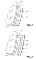
- FIG. 3 Other embodiments of the invention include the application of a conductive layer 36 onto the exterior surface 39 before the application of the contrast enhancing coating 37 as shown in FIG. 3.
- An example of how such a layer 36 can be applied involves first preparing an aqueous formulation having 5 % Baytron Al 4071 by weight and 0.5% hydrolyzed tetraethylorthosilicate. Baytron Al 4071 is available from the Bayer Corp. Next the formulation can be applied to the exterior surface 39 of the faceplate 27 while the faceplate 27 is at room temperature or slightly thereabove. Multiple layers of the conductive layer 36 can be applied to achieve the desired conductance.
- the examples described above have yielded CRTs 21 having gloss measurements from about 70 to about 90 while substantially reducing the transmission of the faceplates 27 from about 80 to 40%.
- the gloss measurement technique substantially conforms to the US Standard ASTM D 523 or US Standard ASTM D 2457 at 60°.
Landscapes
- Vessels, Lead-In Wires, Accessory Apparatuses For Cathode-Ray Tubes (AREA)
- Formation Of Various Coating Films On Cathode Ray Tubes And Lamps (AREA)
Abstract
Description
Claims (24)
- A CRT comprising a funnel having a neck attached to the narrow end of said funnel, an electron gun mounted in said neck, a viewing faceplate attached to a wide end of said funnel and having a luminescent screen on an interior surface of said faceplate, and a contrast enhancing coating on an exterior side of said viewing faceplate, wherein said contrast enhancing coating comprises a silicate binder and at least one contrast enhancing material, said contrast enhancing coating reduces said transmission of visible light by up to 50% and has a 60° gloss value of at least 70 to 90.
- The CRT according to claim 1 wherein said contrast enhancing coating is in intimate contact with an exterior surface of said faceplate.
- The CRT according to claim 1 wherein said silicate binder is derived from an organic silicate binder.
- The CRT according to claim 3 wherein said organic silicate binder is tetraethyl orthosilicate.
- The CRT according to claim 1 wherein said contrast enhancing material is a black pigment, said black pigment comprising at least one material.
- The CRT according to claim 5 wherein said black pigment is selected from a group consisting of Levanyl Black, a mixture of Levanyl Black and Nigrosin Black, and a mixture of Levanyl Black and Sudan Black.
- The CRT according to claim 5 wherein said black pigment comprises carbon black particles having particles in the range 35 to 170 nm.
- The CRT according to claim 1 wherein a mass ratio of said silicate binder to said contrast enhancing material is 9-11:1.
- The CRT according to claim 1 wherein at least one conductive layer is between an exterior surface of said faceplate and said contrast enhancing coating.
- The CRT according to claim 9 wherein at least one conductive layer comprises an organic conductive material and a silicate.
- A method of making a CRT having a contrast enhancing coating on a faceplate of said CRT, said contrast enhancing coating having a silicate binder and at least one contrast enhancing material, said contrast enhancing coating reducing the transmission of visible light through said faceplate by up to 50% and having a 60° gloss value of 70 to 90%, said method comprising the steps of:hydrolyzing an organic silicate in a mixture of an alcohol, an acid and water to provide an intermediate formulation;diluting said intermediate formulation with at least a solvent and adding at least one contrast enhancing material to provide a final formulation;providing a CRT having an exterior side on said faceplate;heating said CRT;spraying said final formulation onto said exterior side to provide a contrast enhancing coating;heating said faceplate to cure said coating; andrinsing said coating.
- The method according to claim 11 wherein said faceplate in the providing step has an uncoated exterior surface to which said final formulation is applied in the spraying step.
- The method according to claim 11 wherein said organic silicate binder is tetraethyl orthosilicate.
- The method according to claim 11 wherein said contrast enhancing material is a neutral density material.
- The method according to claim 11 wherein said contrast enhancing material is a black pigment, said black pigment comprising at least one material.
- The method according to claim 15 wherein said black pigment is selected from a group consisting of Levanyl Black, a mixture of Levanyl Black and Nigrosin Black, and a mixture of Levanyl Black and Sudan Black.
- The method according to claim 15 wherein said black pigment comprises carbon black particles in the range 35 to 170 nm.
- The method according to claim 11 wherein said alcohol is ethanol, said acid is hydrochloric acid, said solvent is acetone, said contrast enhancing material is Levanyl Black, and said organic silicate is tetraethyl orthosilicate.
- The method according to claim 18 wherein said final formulation comprises:45 g of ethanol;1 g of hydrochloric acid;670 g of water;300 g of acetone;4-9 g of Levanyl Black; and50-90 g of tetraethyl orthosilicate.
- The method according to claim 11 wherein the diluting step comprises diluting an intermediate formulation with an organic solvent and water and adding at least one contrast enhancing material to provide a final formulation, wherein said organic solvent is a slow evaporating organic solvent, thereby permitting a slower flash-off during the heating said faceplate step and, in turn, permitting a glossier finish.
- The method according to claim 20 wherein said alcohol is ethanol, said acid is nitric acid, said solvent is 1-propanol; said contrast enhancing material is a mixture of Levanyl Black and Nigrosin Black; and said organic silicate is tetraethyl orthosilicate.
- The method according to claim 21 wherein said final formulation comprises:45 g of ethanol;1 g of nitric acid;1752 g of water;1260 g of 1-propanol;5-8 g of Levanyl Black;2-3 g of Nigrosin Black; and50-90 g of tetraethyl orthosilicate.
- The method according to claim 11 wherein said faceplate in the providing step has an initial coating on said exterior side to which said final formulation is applied in the spraying step.
- The method according to claim 23 wherein said initial coating comprises at least one conductive layer.
Applications Claiming Priority (2)
| Application Number | Priority Date | Filing Date | Title |
|---|---|---|---|
| US218780 | 1988-07-14 | ||
| US10/218,780 US7166957B2 (en) | 2002-08-14 | 2002-08-14 | CRT having a contrast enhancing exterior coating and method of manufacturing the same |
Publications (2)
| Publication Number | Publication Date |
|---|---|
| EP1391910A2 true EP1391910A2 (en) | 2004-02-25 |
| EP1391910A3 EP1391910A3 (en) | 2004-07-28 |
Family
ID=31187929
Family Applications (1)
| Application Number | Title | Priority Date | Filing Date |
|---|---|---|---|
| EP03102372A Withdrawn EP1391910A3 (en) | 2002-08-14 | 2003-07-30 | Crt having a contrast enhancing exterior coating and method of manufacturing the same |
Country Status (9)
| Country | Link |
|---|---|
| US (1) | US7166957B2 (en) |
| EP (1) | EP1391910A3 (en) |
| JP (1) | JP2004079517A (en) |
| KR (1) | KR100545508B1 (en) |
| CN (1) | CN1287411C (en) |
| HU (1) | HUP0302591A3 (en) |
| MX (1) | MXPA03007203A (en) |
| PL (1) | PL361639A1 (en) |
| SG (1) | SG120942A1 (en) |
Families Citing this family (1)
| Publication number | Priority date | Publication date | Assignee | Title |
|---|---|---|---|---|
| KR101015385B1 (en) * | 2008-10-31 | 2011-02-22 | 한국생산기술연구원 | Organic-inorganic hybrid composite thin film coating solution, preparation method thereof and coating method using the same |
Family Cites Families (18)
| Publication number | Priority date | Publication date | Assignee | Title |
|---|---|---|---|---|
| US4694218A (en) * | 1984-05-04 | 1987-09-15 | Cotek Company | Non-glaze coating for a cathode ray tube |
| US4965096A (en) * | 1988-08-25 | 1990-10-23 | Rca Licensing Corp. | Method for preparing improved lithium-silicate glare-reducing coating for a cathode-ray tube |
| US5122709A (en) * | 1989-03-20 | 1992-06-16 | Hitachi, Ltd. | Antistatic cathode ray tube with lobe like projections and high gloss and hardness |
| JPH02269178A (en) | 1989-04-11 | 1990-11-02 | Asahi Glass Co Ltd | Antistatic film and production thereof |
| US5291097A (en) * | 1990-05-14 | 1994-03-01 | Hitachi, Ltd. | Cathode-ray tube |
| US5660876A (en) | 1991-06-07 | 1997-08-26 | Sony Corporation | Method of manufacturing cathode ray tube with a nonglare multi-layered film |
| EP0538937B1 (en) * | 1991-10-23 | 1996-01-03 | Koninklijke Philips Electronics N.V. | Antireflective and antistatic coating for, in particular, a cathode ray tube |
| TW278195B (en) * | 1992-12-21 | 1996-06-11 | Philips Electronics Nv | |
| IT1272666B (en) | 1993-09-23 | 1997-06-26 | Videocolor Spa | Lining of neutral density, for reduced glare, for the frontal surface of a cathode ray tube |
| CN1058105C (en) | 1995-02-14 | 2000-11-01 | 中华映管股份有限公司 | Anti-glare and anti-static coatings on cathode ray tubes |
| IT1277470B1 (en) | 1995-08-09 | 1997-11-10 | Videocolor Spa | MANUFACTURING PROCESS OF A CATHODE-BEAMED TUBE EQUIPPED WITH ANTI-GLARE AND ANTI-DARK FRONT PLATE COVERING |
| TW382724B (en) * | 1998-01-30 | 2000-02-21 | Koninkl Philips Electronics Nv | Method of manufacturing a coating on a display window and a display device comprising a display window provided with a coating |
| JP3397680B2 (en) * | 1998-03-23 | 2003-04-21 | 株式会社東芝 | Method for manufacturing conductive antireflection film and method for manufacturing cathode ray tube |
| ITMI981191A1 (en) | 1998-05-29 | 1999-11-29 | Videocolor Spa | CATHODE TUBE WITH AN ANTISTATIC COLOR COATING ON THE FRONT PANEL AND MANUFACTURING PROCESS OF THE SAME |
| TW430850B (en) * | 1998-12-29 | 2001-04-21 | Koninkl Philips Electronics Nv | Light-transmissive substrate having a light-transmissive, low-ohmic coating |
| JP2000275409A (en) | 1999-01-18 | 2000-10-06 | Sumitomo Metal Mining Co Ltd | Low-transmission transparent base material, its manufacture, and display device employing the same |
| KR100775391B1 (en) * | 2000-06-20 | 2007-11-12 | 가무시키가이샤 도시바 | Transparent film-coated substrates, coating liquids and display devices for forming transparent films |
| US20020113540A1 (en) * | 2001-02-20 | 2002-08-22 | Yuan-Hsiang Yu | Electric shielding and anti-glaring multi-layer coating for cathode ray tube and the method for making the same |
-
2002
- 2002-08-14 US US10/218,780 patent/US7166957B2/en not_active Expired - Fee Related
-
2003
- 2003-07-07 JP JP2003192963A patent/JP2004079517A/en active Pending
- 2003-07-24 SG SG200304032A patent/SG120942A1/en unknown
- 2003-07-30 EP EP03102372A patent/EP1391910A3/en not_active Withdrawn
- 2003-08-12 PL PL03361639A patent/PL361639A1/en not_active Application Discontinuation
- 2003-08-12 MX MXPA03007203A patent/MXPA03007203A/en unknown
- 2003-08-13 HU HU0302591A patent/HUP0302591A3/en unknown
- 2003-08-14 CN CNB031278922A patent/CN1287411C/en not_active Expired - Fee Related
- 2003-08-14 KR KR1020030056353A patent/KR100545508B1/en not_active Expired - Fee Related
Also Published As
| Publication number | Publication date |
|---|---|
| HU0302591D0 (en) | 2003-10-28 |
| MXPA03007203A (en) | 2005-04-19 |
| EP1391910A3 (en) | 2004-07-28 |
| JP2004079517A (en) | 2004-03-11 |
| KR100545508B1 (en) | 2006-01-24 |
| PL361639A1 (en) | 2004-02-23 |
| CN1287411C (en) | 2006-11-29 |
| SG120942A1 (en) | 2006-04-26 |
| US20040032200A1 (en) | 2004-02-19 |
| US7166957B2 (en) | 2007-01-23 |
| KR20040016410A (en) | 2004-02-21 |
| HUP0302591A2 (en) | 2004-04-28 |
| HUP0302591A3 (en) | 2004-11-29 |
| CN1484273A (en) | 2004-03-24 |
Similar Documents
| Publication | Publication Date | Title |
|---|---|---|
| US5750054A (en) | Anti-glare, anti-static coating for a reflective-transmissive surface | |
| JPH0440824B2 (en) | ||
| MXPA97003221A (en) | Anti-reflective, anti-static and met metal coatings | |
| US3898509A (en) | Cathode-ray tube having lithium silicate glare-reducing coating with reduced light transmission and method of fabrication | |
| US6746530B2 (en) | High contrast, moisture resistant antistatic/antireflective coating for CRT display screen | |
| US7166957B2 (en) | CRT having a contrast enhancing exterior coating and method of manufacturing the same | |
| CN1153252C (en) | Conductive antireflecting film and cathode-ray tube | |
| JPH0680903A (en) | Coating material for forming antistatic high-refractive-index film, transparent material laminate provided with antistatic antireflective film, and cathode-ray tube | |
| JPH11283530A (en) | Cathode-ray tube and its manufacture | |
| KR100231658B1 (en) | Method for producing cathode ray tube with dark faceplate coating showing anti-glare and antistatic properties | |
| US5364567A (en) | Solution for preparing a conductive film for a flat brown tube | |
| JPH11283529A (en) | Cathode-ray tube and its manufacture | |
| JPH0588001A (en) | Formation of antireflection film on outside surface of face part of cathode ray tube | |
| JP3466089B2 (en) | Conductive anti-reflection film and cathode ray tube | |
| JPH05182604A (en) | Cathode-ray tube | |
| TH65281A (en) | CRTs with an external coating that reinforce the difference and the same manufacturing methods. | |
| WO1999063569A1 (en) | Cathode-ray tube having a colored, anti-static, faceplate coating and process of manufacturing same | |
| EP1089316A1 (en) | Cathode-ray tube and method for manufacturing the same | |
| CN1055779C (en) | Antistatic and broadband antireflection coating for video display panel and method for its manufacture | |
| JPH1097833A (en) | Panel for cathode-ray tube | |
| JP2002062403A (en) | Light absorbing anti-reflective body | |
| JP2002117790A (en) | Panel for cathode ray tube | |
| JPH09120785A (en) | Coating liquid for forming low resistance film, low resistance film, multilayer low resistance film and glass article | |
| JPH1064453A (en) | Coating for display device | |
| JPH10255693A (en) | Panel for cathode-ray tube |
Legal Events
| Date | Code | Title | Description |
|---|---|---|---|
| PUAI | Public reference made under article 153(3) epc to a published international application that has entered the european phase |
Free format text: ORIGINAL CODE: 0009012 |
|
| AK | Designated contracting states |
Kind code of ref document: A2 Designated state(s): AT BE BG CH CY CZ DE DK EE ES FI FR GB GR HU IE IT LI LU MC NL PT RO SE SI SK TR |
|
| AX | Request for extension of the european patent |
Extension state: AL LT LV MK |
|
| PUAL | Search report despatched |
Free format text: ORIGINAL CODE: 0009013 |
|
| AK | Designated contracting states |
Kind code of ref document: A3 Designated state(s): AT BE BG CH CY CZ DE DK EE ES FI FR GB GR HU IE IT LI LU MC NL PT RO SE SI SK TR |
|
| AX | Request for extension of the european patent |
Extension state: AL LT LV MK |
|
| RIC1 | Information provided on ipc code assigned before grant |
Ipc: 7C 03C 17/00 B Ipc: 7H 01J 9/00 B Ipc: 7H 01J 29/89 A |
|
| 17P | Request for examination filed |
Effective date: 20050110 |
|
| 17Q | First examination report despatched |
Effective date: 20050204 |
|
| AKX | Designation fees paid |
Designated state(s): DE FR GB IT |
|
| RAP1 | Party data changed (applicant data changed or rights of an application transferred) |
Owner name: THOMSON LICENSING |
|
| STAA | Information on the status of an ep patent application or granted ep patent |
Free format text: STATUS: THE APPLICATION IS DEEMED TO BE WITHDRAWN |
|
| 18D | Application deemed to be withdrawn |
Effective date: 20080111 |