EP1391785A1 - Particle barrier for use in a lithographic projection apparatus - Google Patents
Particle barrier for use in a lithographic projection apparatus Download PDFInfo
- Publication number
- EP1391785A1 EP1391785A1 EP03077626A EP03077626A EP1391785A1 EP 1391785 A1 EP1391785 A1 EP 1391785A1 EP 03077626 A EP03077626 A EP 03077626A EP 03077626 A EP03077626 A EP 03077626A EP 1391785 A1 EP1391785 A1 EP 1391785A1
- Authority
- EP
- European Patent Office
- Prior art keywords
- channel means
- optical axis
- projection apparatus
- lithographic projection
- radiation
- Prior art date
- Legal status (The legal status is an assumption and is not a legal conclusion. Google has not performed a legal analysis and makes no representation as to the accuracy of the status listed.)
- Granted
Links
- 230000004888 barrier function Effects 0.000 title description 26
- 239000002245 particle Substances 0.000 title description 16
- 230000005855 radiation Effects 0.000 claims abstract description 72
- 230000003287 optical effect Effects 0.000 claims abstract description 43
- 239000000758 substrate Substances 0.000 claims description 32
- 238000000059 patterning Methods 0.000 claims description 13
- 238000000034 method Methods 0.000 claims description 8
- 238000004519 manufacturing process Methods 0.000 claims description 7
- 239000000463 material Substances 0.000 claims description 5
- 230000001902 propagating effect Effects 0.000 claims description 4
- 239000011888 foil Substances 0.000 abstract description 14
- 238000001900 extreme ultraviolet lithography Methods 0.000 abstract description 2
- 239000010410 layer Substances 0.000 description 9
- 238000005286 illumination Methods 0.000 description 7
- 238000011109 contamination Methods 0.000 description 4
- 238000009304 pastoral farming Methods 0.000 description 4
- 241000446313 Lamella Species 0.000 description 3
- 230000000694 effects Effects 0.000 description 3
- XUIMIQQOPSSXEZ-UHFFFAOYSA-N Silicon Chemical compound [Si] XUIMIQQOPSSXEZ-UHFFFAOYSA-N 0.000 description 2
- 238000003491 array Methods 0.000 description 2
- 238000011161 development Methods 0.000 description 2
- 238000009826 distribution Methods 0.000 description 2
- 238000003384 imaging method Methods 0.000 description 2
- 238000001459 lithography Methods 0.000 description 2
- 239000011159 matrix material Substances 0.000 description 2
- QSHDDOUJBYECFT-UHFFFAOYSA-N mercury Chemical compound [Hg] QSHDDOUJBYECFT-UHFFFAOYSA-N 0.000 description 2
- 229910052753 mercury Inorganic materials 0.000 description 2
- 230000010363 phase shift Effects 0.000 description 2
- 229910052710 silicon Inorganic materials 0.000 description 2
- 239000010703 silicon Substances 0.000 description 2
- WHXSMMKQMYFTQS-UHFFFAOYSA-N Lithium Chemical compound [Li] WHXSMMKQMYFTQS-UHFFFAOYSA-N 0.000 description 1
- 238000000429 assembly Methods 0.000 description 1
- 230000000712 assembly Effects 0.000 description 1
- 230000002238 attenuated effect Effects 0.000 description 1
- 230000005540 biological transmission Effects 0.000 description 1
- 230000015556 catabolic process Effects 0.000 description 1
- 239000011248 coating agent Substances 0.000 description 1
- 238000000576 coating method Methods 0.000 description 1
- 230000003750 conditioning effect Effects 0.000 description 1
- 238000010276 construction Methods 0.000 description 1
- 238000006731 degradation reaction Methods 0.000 description 1
- 238000013461 design Methods 0.000 description 1
- 238000001514 detection method Methods 0.000 description 1
- 230000009977 dual effect Effects 0.000 description 1
- 230000005684 electric field Effects 0.000 description 1
- 239000007772 electrode material Substances 0.000 description 1
- 230000005670 electromagnetic radiation Effects 0.000 description 1
- 238000010894 electron beam technology Methods 0.000 description 1
- 238000005530 etching Methods 0.000 description 1
- 238000002474 experimental method Methods 0.000 description 1
- 238000007689 inspection Methods 0.000 description 1
- 238000005468 ion implantation Methods 0.000 description 1
- 238000010884 ion-beam technique Methods 0.000 description 1
- 239000002346 layers by function Substances 0.000 description 1
- 239000004973 liquid crystal related substance Substances 0.000 description 1
- 229910052744 lithium Inorganic materials 0.000 description 1
- 230000005381 magnetic domain Effects 0.000 description 1
- 238000005259 measurement Methods 0.000 description 1
- 230000015654 memory Effects 0.000 description 1
- 238000001465 metallisation Methods 0.000 description 1
- 230000003647 oxidation Effects 0.000 description 1
- 238000007254 oxidation reaction Methods 0.000 description 1
- 238000005498 polishing Methods 0.000 description 1
- 230000037452 priming Effects 0.000 description 1
- 238000012545 processing Methods 0.000 description 1
- 230000003252 repetitive effect Effects 0.000 description 1
- 239000004065 semiconductor Substances 0.000 description 1
- 238000007493 shaping process Methods 0.000 description 1
- 230000003595 spectral effect Effects 0.000 description 1
- 238000001228 spectrum Methods 0.000 description 1
- 238000003860 storage Methods 0.000 description 1
- 230000001360 synchronised effect Effects 0.000 description 1
- 230000005469 synchrotron radiation Effects 0.000 description 1
- 239000010409 thin film Substances 0.000 description 1
Images


Classifications
-
- G—PHYSICS
- G03—PHOTOGRAPHY; CINEMATOGRAPHY; ANALOGOUS TECHNIQUES USING WAVES OTHER THAN OPTICAL WAVES; ELECTROGRAPHY; HOLOGRAPHY
- G03F—PHOTOMECHANICAL PRODUCTION OF TEXTURED OR PATTERNED SURFACES, e.g. FOR PRINTING, FOR PROCESSING OF SEMICONDUCTOR DEVICES; MATERIALS THEREFOR; ORIGINALS THEREFOR; APPARATUS SPECIALLY ADAPTED THEREFOR
- G03F7/00—Photomechanical, e.g. photolithographic, production of textured or patterned surfaces, e.g. printing surfaces; Materials therefor, e.g. comprising photoresists; Apparatus specially adapted therefor
- G03F7/70—Microphotolithographic exposure; Apparatus therefor
- G03F7/70058—Mask illumination systems
- G03F7/7015—Details of optical elements
- G03F7/70166—Capillary or channel elements, e.g. nested extreme ultraviolet [EUV] mirrors or shells, optical fibers or light guides
-
- G—PHYSICS
- G03—PHOTOGRAPHY; CINEMATOGRAPHY; ANALOGOUS TECHNIQUES USING WAVES OTHER THAN OPTICAL WAVES; ELECTROGRAPHY; HOLOGRAPHY
- G03F—PHOTOMECHANICAL PRODUCTION OF TEXTURED OR PATTERNED SURFACES, e.g. FOR PRINTING, FOR PROCESSING OF SEMICONDUCTOR DEVICES; MATERIALS THEREFOR; ORIGINALS THEREFOR; APPARATUS SPECIALLY ADAPTED THEREFOR
- G03F7/00—Photomechanical, e.g. photolithographic, production of textured or patterned surfaces, e.g. printing surfaces; Materials therefor, e.g. comprising photoresists; Apparatus specially adapted therefor
- G03F7/20—Exposure; Apparatus therefor
-
- G—PHYSICS
- G03—PHOTOGRAPHY; CINEMATOGRAPHY; ANALOGOUS TECHNIQUES USING WAVES OTHER THAN OPTICAL WAVES; ELECTROGRAPHY; HOLOGRAPHY
- G03F—PHOTOMECHANICAL PRODUCTION OF TEXTURED OR PATTERNED SURFACES, e.g. FOR PRINTING, FOR PROCESSING OF SEMICONDUCTOR DEVICES; MATERIALS THEREFOR; ORIGINALS THEREFOR; APPARATUS SPECIALLY ADAPTED THEREFOR
- G03F7/00—Photomechanical, e.g. photolithographic, production of textured or patterned surfaces, e.g. printing surfaces; Materials therefor, e.g. comprising photoresists; Apparatus specially adapted therefor
- G03F7/70—Microphotolithographic exposure; Apparatus therefor
- G03F7/70058—Mask illumination systems
-
- G—PHYSICS
- G03—PHOTOGRAPHY; CINEMATOGRAPHY; ANALOGOUS TECHNIQUES USING WAVES OTHER THAN OPTICAL WAVES; ELECTROGRAPHY; HOLOGRAPHY
- G03F—PHOTOMECHANICAL PRODUCTION OF TEXTURED OR PATTERNED SURFACES, e.g. FOR PRINTING, FOR PROCESSING OF SEMICONDUCTOR DEVICES; MATERIALS THEREFOR; ORIGINALS THEREFOR; APPARATUS SPECIALLY ADAPTED THEREFOR
- G03F7/00—Photomechanical, e.g. photolithographic, production of textured or patterned surfaces, e.g. printing surfaces; Materials therefor, e.g. comprising photoresists; Apparatus specially adapted therefor
- G03F7/70—Microphotolithographic exposure; Apparatus therefor
- G03F7/708—Construction of apparatus, e.g. environment aspects, hygiene aspects or materials
-
- G—PHYSICS
- G03—PHOTOGRAPHY; CINEMATOGRAPHY; ANALOGOUS TECHNIQUES USING WAVES OTHER THAN OPTICAL WAVES; ELECTROGRAPHY; HOLOGRAPHY
- G03F—PHOTOMECHANICAL PRODUCTION OF TEXTURED OR PATTERNED SURFACES, e.g. FOR PRINTING, FOR PROCESSING OF SEMICONDUCTOR DEVICES; MATERIALS THEREFOR; ORIGINALS THEREFOR; APPARATUS SPECIALLY ADAPTED THEREFOR
- G03F7/00—Photomechanical, e.g. photolithographic, production of textured or patterned surfaces, e.g. printing surfaces; Materials therefor, e.g. comprising photoresists; Apparatus specially adapted therefor
- G03F7/70—Microphotolithographic exposure; Apparatus therefor
- G03F7/708—Construction of apparatus, e.g. environment aspects, hygiene aspects or materials
- G03F7/70808—Construction details, e.g. housing, load-lock, seals or windows for passing light in or out of apparatus
- G03F7/70825—Mounting of individual elements, e.g. mounts, holders or supports
-
- G—PHYSICS
- G03—PHOTOGRAPHY; CINEMATOGRAPHY; ANALOGOUS TECHNIQUES USING WAVES OTHER THAN OPTICAL WAVES; ELECTROGRAPHY; HOLOGRAPHY
- G03F—PHOTOMECHANICAL PRODUCTION OF TEXTURED OR PATTERNED SURFACES, e.g. FOR PRINTING, FOR PROCESSING OF SEMICONDUCTOR DEVICES; MATERIALS THEREFOR; ORIGINALS THEREFOR; APPARATUS SPECIALLY ADAPTED THEREFOR
- G03F7/00—Photomechanical, e.g. photolithographic, production of textured or patterned surfaces, e.g. printing surfaces; Materials therefor, e.g. comprising photoresists; Apparatus specially adapted therefor
- G03F7/70—Microphotolithographic exposure; Apparatus therefor
- G03F7/708—Construction of apparatus, e.g. environment aspects, hygiene aspects or materials
- G03F7/70908—Hygiene, e.g. preventing apparatus pollution, mitigating effect of pollution or removing pollutants from apparatus
- G03F7/70916—Pollution mitigation, i.e. mitigating effect of contamination or debris, e.g. foil traps
-
- G—PHYSICS
- G03—PHOTOGRAPHY; CINEMATOGRAPHY; ANALOGOUS TECHNIQUES USING WAVES OTHER THAN OPTICAL WAVES; ELECTROGRAPHY; HOLOGRAPHY
- G03F—PHOTOMECHANICAL PRODUCTION OF TEXTURED OR PATTERNED SURFACES, e.g. FOR PRINTING, FOR PROCESSING OF SEMICONDUCTOR DEVICES; MATERIALS THEREFOR; ORIGINALS THEREFOR; APPARATUS SPECIALLY ADAPTED THEREFOR
- G03F7/00—Photomechanical, e.g. photolithographic, production of textured or patterned surfaces, e.g. printing surfaces; Materials therefor, e.g. comprising photoresists; Apparatus specially adapted therefor
- G03F7/70—Microphotolithographic exposure; Apparatus therefor
- G03F7/708—Construction of apparatus, e.g. environment aspects, hygiene aspects or materials
- G03F7/70983—Optical system protection, e.g. pellicles or removable covers for protection of mask
Definitions
- the invention relates to a lithographic projection apparatus comprising:
- patterning means as here employed should be broadly interpreted as referring to means that can be used to endow an incoming radiation beam with a patterned cross-section, corresponding to a pattern that is to be created in a target portion of the substrate; the term “light valve” can also be used in this context.
- the said pattern will correspond to a particular functional layer in a device being created in the target portion, such as an integrated circuit or other device (see below). Examples of such patterning means include:
- Lithographic projection apparatus can be used, for example, in the manufacture of integrated circuits (ICs).
- the patterning means may generate a circuit pattern corresponding to an individual layer of the IC, and this pattern can be imaged onto a target portion (e.g. comprising one or more dies) on a substrate (silicon wafer) that has been coated with a layer of radiation-sensitive material (resist).
- a target portion e.g. comprising one or more dies
- a substrate silicon wafer
- a layer of radiation-sensitive material resist
- a single wafer will contain a whole network of adjacent target portions that are successively irradiated via the projection system, one at a time.
- employing patterning by a mask on a mask table a distinction can be made between two different types of machine.
- each target portion is irradiated by exposing the entire mask pattern onto the target portion in one go; such an apparatus is commonly referred to as a wafer stepper or step-and-repeat apparatus.
- a wafer stepper or step-and-repeat apparatus In an alternative apparatus ⁇ commonly referred to as a step-and-scan apparatus ⁇ each target portion is irradiated by progressively scanning the mask pattern under the projection beam in a given reference direction (the "scanning" direction) while synchronously scanning the substrate table parallel or anti-parallel to this direction; since, in general, the projection system will have a magnification factor M (generally ⁇ 1), the speed V at which the substrate table is scanned will be a factor M times that at which the mask table is scanned. More information with regard to lithographic devices as here described can be gleaned, for example, from US 6,046,792, incorporated herein by reference.
- a pattern (e.g. in a mask) is imaged onto a substrate that is at least partially covered by a layer of radiation-sensitive material (resist).
- the substrate Prior to this imaging step, the substrate may undergo various procedures, such as priming, resist coating and a soft bake. After exposure, the substrate may be subjected to other procedures, such as a post-exposure bake (PEB), development, a hard bake and measurement/inspection of the imaged features.
- PEB post-exposure bake
- This array of procedures is used as a basis to pattern an individual layer of a device, e.g. an IC.
- Such a patterned layer may then undergo various processes such as etching, ion-implantation (doping), metallization, oxidation, chemo-mechanical polishing, etc., all intended to finish off an individual layer. If several layers are required, then the whole procedure, or a variant thereof, will have to be repeated for each new layer. Eventually, an array of devices will be present on the substrate (wafer). These devices are then separated from one another by a technique such as dicing or sawing, whence the individual devices can be mounted on a carrier, connected to pins, etc.
- the projection system may hereinafter be referred to as the "lens"; however, this term should be broadly interpreted as encompassing various types of projection system, including refractive optics, reflective optics, and catadioptric systems, for example.
- the radiation system may also include components operating according to any of these design types for directing, shaping or controlling the projection beam of radiation, and such components may also be referred to below, collectively or singularly, as a "lens".
- the lithographic apparatus may be of a type having two or more substrate tables (and/or two or more mask tables). In such "multiple stage” devices the additional tables may be used in parallel, or preparatory steps may be carried out on one or more tables while one or more other tables are being used for exposures. Dual stage lithographic apparatus are described, for example, in US 5,969,441 and WO 98/40791, both incorporated herein by reference.
- lithographic projection apparatus In a lithographic apparatus the size of features that can be imagined onto the substrate is limited by the wavelength of the projection radiation. To produce integrated circuits with a higher density of devices, and hence higher operating speeds, it is desirable to be able to image smaller features. Whilst most current lithographic projection apparatus employ ultraviolet light generated by mercury lamps or excimer lasers, it has been proposed to use shorter wavelength radiation in the range 5 to 20 nm, especially around 13 nm. Such radiation is termed extreme ultraviolet (EUV) or soft x-ray and possible sources include, for instance, laser-produced plasma sources, discharge plasma sources, or synchrotron radiation from electron storage rings. Apparatus using discharge plasma sources are described in: W. Partlo, I. Fomenkov, R. Oliver, D.
- EUV extreme ultraviolet
- EUV radiation sources such as discharge plasma radiation sources referred to above, may require the use of a rather high partial pressure of a gas or vapor to emit EUV radiation.
- a discharge plasma source for instance, a discharge is created in between electrodes, and a resulting partially ionized plasma may subsequently be caused to collapse to yield a very hot plasma that emits radiation in the EUV range.
- the very hot plasma is quite often created in Xe, since a Xe plasma radiates in the Extreme UV (EUV) range around 13.5 nm.
- EUV Extreme UV
- a typical pressure of 0.1 mbar is required near the electrodes to the radiation source.
- a drawback of having such a rather high Xe pressure is that Xe gas absorbs EUV radiation.
- 0.1 mbar Xe transmits over 1 m only 0.3 % EUV radiation having a wavelength of 13.5 nm. It is therefore required to confine the rather high Xe pressure to a limited region around the source.
- the source can be contained in its own vacuum chamber that is separated by a chamber wall from a subsequent vacuum chamber in which the collector mirror and illumination optics may be obtained.
- the vacuum wall can be made transparant to EUV radiation by a number of apertures in said wall provided by a channel array or so called foil trap such as described in European Patent application number EP-A-1 057 079 which is incorporated herein by reference.
- a channel array or "foil trap” has been proposed in EP-A-1 223 468 and EP-A-1 057 079.
- This foil trap consists of a channel like structure comprising lamella shaped walls close together in order to form a flow resistance but not too close as to let the radiation pass without obstructing it. This foil trap is incorporated herein by reference.
- a lithographic projection apparatus as specified in the opening paragraph, characterized in that the channel means is rotatable around the optical axis, the lithographic projection apparatus comprising drive means connected to the channel means for rotating the channel means around the optical axis.
- the rotating channel means particles emitted from the EUV source and travelling along the optical axis, are intercepted by the walls of the channel means which travel perpendicular to the optical axis and will stick there. In this way, the delicate optical components behind the channel means will be guarded against contamination.
- the lithographic projection apparatus is characterized in that the channel members are focussed on the radiation source.
- EUV rays of radiation emitted from the EUV source may pass the channel means without substantial obstruction. This is an important advantage because EUV radiation tends to be absorbed very easily.
- the velocity of the heavy particles, such as debris comprising ablate, evaporated or sputtered electrode material emanating from the source is relatively low. From experiments, the speeds appear to be lower than 10 m/s.
- the lithographic projection apparatus is characterized in that the drive means are adapted to rotate the channel means at a speed of between 1 and 50 rotations per second, preferably 1 and 10 rotations per second.
- supplementary channel means are rotatably mounted with respect to said optical axis near the channel means, it being particularly advantageous when said supplementary channel means has a direction of rotation opposite to the direction of rotation of said channel means.
- some fast moving contaminating particles may have passed one of the channel means at a certain angle almost certainly will not pass the next one because the angle of it relatively to the askew going particles will be different.
- said supplementary channel means has substantially the same direction of rotation as the direction of rotation of said channel means, and has a rotational velocity different from the rotational velocity of the channel means, or even wherein said supplementary channel means is non-rotationally mounted.
- EUV extreme ultra-violet
- Fig. 1 schematically depicts a lithographic projection apparatus 1 according to a particular embodiment of the invention.
- the apparatus comprises:
- the source LA (e.g. a laser-produced plasma or a discharge plasma EUV radiation source) produces a beam of radiation.
- This beam is fed into an illumination system (illuminator) IL, either directly or after having traversed conditioning means, such as a beam expander, for example.
- the illuminator IL may comprise adjusting means for setting the outer and/or inner radial extent (commonly referred to as ⁇ -outer and ⁇ -inner, respectively) of the intensity distribution in the beam.
- ⁇ -outer and ⁇ -inner commonly referred to as ⁇ -outer and ⁇ -inner, respectively
- it will generally comprise various other components, such as an integrator and a condenser. In this way, the beam PB impinging on the mask MA has a desired uniformity and intensity distribution in its cross-section.
- the source LA may be within the housing of the lithographic projection apparatus (as is often the case when the source LA is a mercury lamp, for example), but that it may also be remote from the lithographic projection apparatus, the radiation beam which it produces being led into the apparatus (e.g. with the aid of suitable directing mirrors); this latter scenario is often the case when the source LA is an excimer laser.
- the current invention and claims encompass both of these scenarios.
- the beam PB subsequently intercepts the mask MA, which is held on a mask table MT. Having been selectively reflected the mask MA, the bearn PB passes through the lens PL, which focuses the beam PB onto a target portion C of the substrate W. With the aid of the second positioning means PW (and interferometric measuring means IF), the substrate table WT can be moved accurately, e.g. so as to position different target portions C in the path of the beam PB. Similarly, the first positioning means PM can be used to accurately position the mask MA with respect to the path of the beam PB, e.g. after mechanical retrieval of the mask MA from a mask library, or during a scan.
- the mask table MT may just be connected to a short stroke actuator, or may be fixed.
- Mask MA and substrate W may be aligned using mask alignment marks M1, M2 and substrate alignment marks P1, P2.
- the depicted apparatus can be used in two different modes:
- Fig. 2 shows the projection apparatus 1 comprising an illumination system with radiation unit 3, illumination optics unit 4, and projection optics system 5.
- the radiation system 2 comprises a source-collector module or radiation unit 3 and an illumination optics unit 4.
- Radiation unit 3 is provided with a radiation source 6 which may be formed by a discharge plasma.
- EUV radiation source 6 may employ a gas or vapor, such as Xe gas or Li vapor in which a very hot plasma may be created to emit radiation in the EUV range of the electromagnetic spectrum.
- the very hot plasma is created by causing a partially ionized plasma of an electrical discharge to collapse onto the optical axis O. Partial pressures of 0.1 mbar of Xe, Li vapor or any other suitable gas or vapor may be required for efficient generation of the radiation.
- the radiation emitted by radiation source 6 is passed from the source chamber 7 into collector chamber 8 via a gas barrier structure or "foil trap" 9.
- the gas barrier structure comprises a channel structure such as, for instance, described in detail in European patent applications EP-A-1 233 468 and EP-A-1 057 079, which are incorporated herein by reference.
- the collector chamber 8 comprises a radiation collector 10 which according to the present invention is formed by a grazing incidence collector. Radiation passed by collector 10 is reflected off a grating spectral filter 11 or mirror to be focused in a virtual source point 12 at an aperture in the collector chamber 8. From chamber 8, the projection beam 16 is reflected in illumination optics unit 4 via normal incidence reflectors 13, 14 onto a reticle or mask positioned on reticle or mask table 15. A patterned beam 17 is formed which is imaged in projection optics system 5 via reflective elements 18, 19 onto wafer stage or substrate table 20. More elements than shown may generally be present in illumination optics unit 4 and projection system 5.
- the grazing incidence collector 10 comprises a number of nested reflector elements 21, 22, 23.
- a grazing incidence collector of this type is, for instance, shown in German patent application DE 101 38 284.7.
- the embodiment of the rotating channel array or barrier 43 according to the invention as shown in figure 4 shows the EUV source 6 from which EUV radiation 6' emanates.
- the beams 6' impinge on the barrier 43 forming part of a vacuum wall separating the source chamber from the UV optics downstream of the optical axis.
- the barrier 43 is rotatable around the optical axis O, as indicated by the arrow. It is also possible for the barrier 43 to rotate around the optical axis O in a direction opposite to the direction of the arrow or alternately rotate in one direction or the other.
- the center 44 of the barrier 43 is located on the optical axis.
- the barrier 43 may be cylindrically symmetric along an optical axis O. The barrier may also be invariant when rotated over some specific angles only.
- the barrier 43 comprises a lamellar structure 41.
- the mutual distance between the different lamellas can vary as shown for a segment 42 of the barrier 43. This means that the distance between consecutive lamellas may vary.
- the lamellar structure 41 forms viewed in 3D, small channels. The channels may be focussed on the radiation source 6. It is also possible to construct a channel array 43 without a real focus. The channels are, however, parallel with the emitted EUV beam.
- the principal idea behind the invention is that contaminating particles 45 in the EUV radiation 6' will, due to rotation of the barrier 43 stick to the inside of the lamellar structure 41 through which the EUV radiation 6' propagates.
- the barrier 43 is rotatable for instance by drive means 46 located on both sides of the barrier 43, with rotational speeds of about 7 rotations per second.
- the lamellar structure 41 is focussed on the radiation source.
- EUV rays of radiation emitted from the EUV source may pass the lamellar structure 41 without obstruction.
- Typical values for the dimensions of the lamellar structure 41 are: platelets: height 30 mm, thickness 0.1 mm and width 50 mm (curved).
- a typical value for the channel width is 1 mm.
- the distance from the barrier 43 to the source 6 is typically in the order of 60 mm.
- the foil trap When the rotation of the foil trap is not synchronized with the pulse frequency of the source, stroboscopic effects can occur. To circumvent stroboscopic effects, the foil trap could be rotated exactly an integer number of channels in between two pulses of the source.
- Fig. 5 shows a barrier assembly 47 comprised of barriers 43 and 43' driven by separate drive means 46 and 46', respectively.
- barriers 43 and 43' rotate in opposite directions, as indicated by arrows A1 and A2, around the optical axis O.
- This barrier assembly is able to prevent fast moving contaminating particles (thermal or with velocities several times higher than thermal) emanating from the EUV source (or thermalized in the volume between the source and the said foil traps) to escape from the source chamber and reach the collector chamber.
- This may also be achieved by similar barrier assemblies, wherein one barrier 43 is rotating and the other barrier 43' is stationary, or wherein both barriers 43, 43'rotate in the same direction, however with different velocities.
Landscapes
- Physics & Mathematics (AREA)
- General Physics & Mathematics (AREA)
- Health & Medical Sciences (AREA)
- Epidemiology (AREA)
- Public Health (AREA)
- Engineering & Computer Science (AREA)
- Environmental & Geological Engineering (AREA)
- Life Sciences & Earth Sciences (AREA)
- Atmospheric Sciences (AREA)
- Exposure And Positioning Against Photoresist Photosensitive Materials (AREA)
- Exposure Of Semiconductors, Excluding Electron Or Ion Beam Exposure (AREA)
Abstract
Description
- The invention relates to a lithographic projection apparatus comprising:
- a radiation system to form a projection beam of radiation, from radiation emitted by a radiation source,
- a support structure constructed to hold patterning means, to be irradiated by the projection beam to pattern said projection beam,
- a substrate table constructed to hold a substrate, and
- a projection system constructed and arranged to image an irradiated portion of the patterning means onto a target portion of the substrate, and
- a channel means near the radiation source for preventing material emanating from the radiation source from propagating along an optical axis, the channel means comprising a center and a number of elongated channel members having a width direction transverse to the optical axis and a length direction extending generally in the direction of the optical axis.
- The term "patterning means" as here employed should be broadly interpreted as referring to means that can be used to endow an incoming radiation beam with a patterned cross-section, corresponding to a pattern that is to be created in a target portion of the substrate; the term "light valve" can also be used in this context. Generally, the said pattern will correspond to a particular functional layer in a device being created in the target portion, such as an integrated circuit or other device (see below). Examples of such patterning means include:
- A mask. The concept of a mask is well known in lithography, and it includes mask types such as binary, alternating phase-shift, and attenuated phase-shift, as well as various hybrid mask types. Placement of such a mask in the radiation beam causes selective transmission (in the case of a transmissive mask) or reflection (in the case of a reflective mask) of the radiation impinging on the mask, according to the pattern on the mask. In the case of a mask, the support structure will generally be a mask table, which ensures that the mask can be held at a desired position in the incoming radiation beam, and that it can be moved relative to the beam if so desired;
- A programmable mirror array. One example of such a device is a matrix-addressable surface having a viscoelastic control layer and a reflective surface. The basic principle behind such an apparatus is that (for example) addressed areas of the reflective surface reflect incident light as diffracted light, whereas unaddressed areas reflect incident light as undiffracted light. Using an appropriate filter, the said undiffracted light can be filtered out of the reflected beam, leaving only the diffracted light behind; in this manner, the beam becomes patterned according to the addressing pattern of the matrix-adressable surface. An alternative embodiment of a programmable mirror array employs a matrix arrangement of tiny mirrors, each of which can be individually tilted about an axis by applying a suitable localized electric field, or by employing piezoelectric actuation means. Once again, the mirrors are matrix-addressable, such that addressed mirrors will reflect an incoming radiation beam in a different direction to unaddressed mirrors; in this manner, the reflected beam is patterned according to the addressing pattern of the matrix-adressable mirrors. The required matrix addressing can be performed using suitable electronic means. In both of the situations described hereabove, the patterning means can comprise one or more programmable mirror arrays. More information on mirror arrays as here referred to can be gleaned, for example, from United States Patents US 5,296,891 and US 5,523,193, and PCT patent applications WO 98/38597 and WO 98/33096, which are incorporated herein by reference. In the case of a programmable mirror array, the said support structure may be embodied as a frame or table, for example, which may be fixed or movable as required; and
- A programmable LCD array. An example of such a construction is given in United States Patent US 5,229,872, which is incorporated herein by reference. As above, the support structure in this case may be embodied as a frame or table, for example, which may be fixed or movable as required.
- Lithographic projection apparatus can be used, for example, in the manufacture of integrated circuits (ICs). In such a case, the patterning means may generate a circuit pattern corresponding to an individual layer of the IC, and this pattern can be imaged onto a target portion (e.g. comprising one or more dies) on a substrate (silicon wafer) that has been coated with a layer of radiation-sensitive material (resist). In general, a single wafer will contain a whole network of adjacent target portions that are successively irradiated via the projection system, one at a time. In current apparatus, employing patterning by a mask on a mask table, a distinction can be made between two different types of machine. In one type of lithographic projection apparatus, each target portion is irradiated by exposing the entire mask pattern onto the target portion in one go; such an apparatus is commonly referred to as a wafer stepper or step-and-repeat apparatus. In an alternative apparatus ― commonly referred to as a step-and-scan apparatus ― each target portion is irradiated by progressively scanning the mask pattern under the projection beam in a given reference direction (the "scanning" direction) while synchronously scanning the substrate table parallel or anti-parallel to this direction; since, in general, the projection system will have a magnification factor M (generally < 1), the speed V at which the substrate table is scanned will be a factor M times that at which the mask table is scanned. More information with regard to lithographic devices as here described can be gleaned, for example, from US 6,046,792, incorporated herein by reference.
- In a manufacturing process using a lithographic projection apparatus, a pattern (e.g. in a mask) is imaged onto a substrate that is at least partially covered by a layer of radiation-sensitive material (resist). Prior to this imaging step, the substrate may undergo various procedures, such as priming, resist coating and a soft bake. After exposure, the substrate may be subjected to other procedures, such as a post-exposure bake (PEB), development, a hard bake and measurement/inspection of the imaged features. This array of procedures is used as a basis to pattern an individual layer of a device, e.g. an IC. Such a patterned layer may then undergo various processes such as etching, ion-implantation (doping), metallization, oxidation, chemo-mechanical polishing, etc., all intended to finish off an individual layer. If several layers are required, then the whole procedure, or a variant thereof, will have to be repeated for each new layer. Eventually, an array of devices will be present on the substrate (wafer). These devices are then separated from one another by a technique such as dicing or sawing, whence the individual devices can be mounted on a carrier, connected to pins, etc. Further information regarding such processes can be obtained, for example, from the book "Microchip Fabrication: A Practical Guide to Semiconductor Processing", Third Edition, by Peter van Zant, McGraw Hill Publishing Co., 1997,
ISBN 0-07-067250-4, incorporated herein by reference. - For the sake of simplicity, the projection system may hereinafter be referred to as the "lens"; however, this term should be broadly interpreted as encompassing various types of projection system, including refractive optics, reflective optics, and catadioptric systems, for example. The radiation system may also include components operating according to any of these design types for directing, shaping or controlling the projection beam of radiation, and such components may also be referred to below, collectively or singularly, as a "lens". Further, the lithographic apparatus may be of a type having two or more substrate tables (and/or two or more mask tables). In such "multiple stage" devices the additional tables may be used in parallel, or preparatory steps may be carried out on one or more tables while one or more other tables are being used for exposures. Dual stage lithographic apparatus are described, for example, in US 5,969,441 and WO 98/40791, both incorporated herein by reference.
- In a lithographic apparatus the size of features that can be imagined onto the substrate is limited by the wavelength of the projection radiation. To produce integrated circuits with a higher density of devices, and hence higher operating speeds, it is desirable to be able to image smaller features. Whilst most current lithographic projection apparatus employ ultraviolet light generated by mercury lamps or excimer lasers, it has been proposed to use shorter wavelength radiation in the
range 5 to 20 nm, especially around 13 nm. Such radiation is termed extreme ultraviolet (EUV) or soft x-ray and possible sources include, for instance, laser-produced plasma sources, discharge plasma sources, or synchrotron radiation from electron storage rings. Apparatus using discharge plasma sources are described in: W. Partlo, I. Fomenkov, R. Oliver, D. Birx, "Development of an EUV (13.5 nm) Light Source Employing a Dense Plasma Focus in Lithium Vapor", Proc. SPIE 3997, pp. 136-156 (2000); M.W. McGeoch, Tower Scaling of a Z-pinch Extreme Ultraviolet Source", Proc. SPIE 3997, pp. 861-866 (2000); W.T. Silfvast, M. Klosner, G. Shimkaveg, H. Bender, G. Kubiak, N. Fornaciari, "High-Power Plasma Discharge Source at 13.5 and 11.4 nm for EUV lithography", Proc. SPIE 3676, pp. 272-275 (1999); and K. Bergmann et al., "Highly Repetitive, Extreme Ultraviolet Radiation Source Based on a Gas-Discharge Plasma", Applied Optics, Vol. 38, pp. 5413-5417 (1999). - EUV radiation sources, such as discharge plasma radiation sources referred to above, may require the use of a rather high partial pressure of a gas or vapor to emit EUV radiation. In a discharge plasma source, for instance, a discharge is created in between electrodes, and a resulting partially ionized plasma may subsequently be caused to collapse to yield a very hot plasma that emits radiation in the EUV range. The very hot plasma is quite often created in Xe, since a Xe plasma radiates in the Extreme UV (EUV) range around 13.5 nm. For an efficient EUV production, a typical pressure of 0.1 mbar is required near the electrodes to the radiation source. A drawback of having such a rather high Xe pressure is that Xe gas absorbs EUV radiation. For example, 0.1 mbar Xe transmits over 1 m only 0.3 % EUV radiation having a wavelength of 13.5 nm. It is therefore required to confine the rather high Xe pressure to a limited region around the source. To achieve this the source can be contained in its own vacuum chamber that is separated by a chamber wall from a subsequent vacuum chamber in which the collector mirror and illumination optics may be obtained.
- The vacuum wall can be made transparant to EUV radiation by a number of apertures in said wall provided by a channel array or so called foil trap such as described in European Patent application number EP-A-1 057 079 which is incorporated herein by reference. In order to reduce the number of particles propagating along the optical axis a channel array or "foil trap" has been proposed in EP-A-1 223 468 and EP-A-1 057 079. This foil trap consists of a channel like structure comprising lamella shaped walls close together in order to form a flow resistance but not too close as to let the radiation pass without obstructing it. This foil trap is incorporated herein by reference.
- The contamination of the optical components of the lithography apparatus by relatively heavy, micron-sized particles or smaller particles having a relatively low velocity, which are emitted by the EUV source and which pass the channel array in the vacuum wall of the source poses a serious problem, as this contamination results in degradation of the optical components and considerably increases the operational costs of an EUV lithographic projection apparatus.
- It is therefore an object of the present invention to reduce the number of particles or eliminate the particles that are emitted by the EUV source and that propagate along the optical axis.
- It is another object to reduce the amount of contamination caused by the EUV source on optical components in an EUV lithographic projection apparatus.
- This and other objects are achieved according to the present invention in a lithographic projection apparatus as specified in the opening paragraph, characterized in that the channel means is rotatable around the optical axis, the lithographic projection apparatus comprising drive means connected to the channel means for rotating the channel means around the optical axis. By means of the rotating channel means particles emitted from the EUV source and travelling along the optical axis, are intercepted by the walls of the channel means which travel perpendicular to the optical axis and will stick there. In this way, the delicate optical components behind the channel means will be guarded against contamination.
- In an embodiment of a lithographic projection apparatus according to the invention, the lithographic projection apparatus is characterized in that the channel members are focussed on the radiation source. Hereby EUV rays of radiation emitted from the EUV source may pass the channel means without substantial obstruction. This is an important advantage because EUV radiation tends to be absorbed very easily.
- The velocity of the heavy particles, such as debris comprising ablate, evaporated or sputtered electrode material emanating from the source is relatively low. From experiments, the speeds appear to be lower than 10 m/s. The aspect ratio of the channel members in the channel means (length/width ratio) is in the order of 20. When the channel means is rotated at a velocity of 10/20 = 0,5 m/s, virtually all the heavy particles emitted by the EUV source will hit the channel member walls and will be trapped in the walls.
- In a further embodiment of the invention therefore the lithographic projection apparatus is characterized in that the drive means are adapted to rotate the channel means at a speed of between 1 and 50 rotations per second, preferably 1 and 10 rotations per second. These relatively low rotational velocities can be easily accomplished and no specialized, advanced and complex components are necessary.
- According to an advantageous embodiment of the invention supplementary channel means are rotatably mounted with respect to said optical axis near the channel means, it being particularly advantageous when said supplementary channel means has a direction of rotation opposite to the direction of rotation of said channel means. In that case some fast moving contaminating particles may have passed one of the channel means at a certain angle almost certainly will not pass the next one because the angle of it relatively to the askew going particles will be different.
- Similar advantageous effects can be achieved in the embodiment according to the invention wherein said supplementary channel means has substantially the same direction of rotation as the direction of rotation of said channel means, and has a rotational velocity different from the rotational velocity of the channel means, or even wherein said supplementary channel means is non-rotationally mounted.
- Although specific reference may be made in this text to the use of the apparatus according to the invention in the manufacture of ICs, it should be explicitly understood that such an apparatus has many other possible applications. For example, it may be employed in the manufacture of integrated optical systems, guidance and detection patterns for magnetic domain memories, liquid-crystal display panels, thin-film magnetic heads, etc. The skilled artisan will appreciate that, in the context of such alternative applications, any use of the terms "reticle", "wafer" or "die" in this text should be considered as being replaced by the more general terms "mask", "substrate" and "target portion", respectively.
In the present document, the terms "radiation" and "beam" are used to encompass all types of electromagnetic radiation, including ultraviolet (UV) radiation (e.g. with a wavelength of 365, 248, 193, 157 or 126 nm) and extreme ultra-violet (EUV) radiation (e.g. having a wavelength in the range 5-20 nm), as well as particle beams, such as ion beams or electron beams. - Embodiments of the invention will now be described, by way of example only, with reference to the accompanying schematic drawings in which corresponding reference symbols indicate corresponding parts, and in which:
- Fig. 1 schematically depicts a lithographic projection apparatus according to an embodiment of the invention;
- Fig. 2. shows a side view of an EUV illuminating system and projection optics of a lithographic projection apparatus according to the invention;
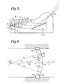
- Fig. 3 shows a detail of the radiation source and grazing incidence collector of the present invention;
- Fig 4 shows in a cross-section a schematic drawing of the rotating particle barrier means according to the present invention; and
- Fig 5 shows in a cross-section a schematic drawing of two contra-rotating particle barrier means according to the present invention.
-
- Fig. 1 schematically depicts a
lithographic projection apparatus 1 according to a particular embodiment of the invention. The apparatus comprises: - a radiation system IL, for supplying a projection beam PB of radiation (e.g. EUV radiation with a wavelength of 11-14 nm). In this particular case, the radiation system also comprises a radiation source LA;
- a first object table (mask table) MT provided with a mask holder for holding a mask MA (e.g. a reticle), and connected to first positioning means PM for accurately positioning the mask with respect to item PL;
- a second object table (substrate table) WT provided with a substrate holder for holding a substrate W (e.g. a resist-coated silicon wafer), and connected to second positioning means PW for accurately positioning the substrate with respect to item PL; and
- a projection system ("lens") PL for imaging an irradiated portion of the mask MA onto a target portion C (e.g. comprising one or more dies) of the substrate W. As here depicted, the apparatus is of a reflective type (i.e. has a reflective mask). However, in general, it may also be of a transmissive type, for example (with a transmissive mask). Alternatively, the apparatus may employ another kind of patterning means, such as a programmable mirror array of a type as referred to above.
- The source LA (e.g. a laser-produced plasma or a discharge plasma EUV radiation source) produces a beam of radiation. This beam is fed into an illumination system (illuminator) IL, either directly or after having traversed conditioning means, such as a beam expander, for example. The illuminator IL may comprise adjusting means for setting the outer and/or inner radial extent (commonly referred to as σ-outer and σ-inner, respectively) of the intensity distribution in the beam. In addition, it will generally comprise various other components, such as an integrator and a condenser. In this way, the beam PB impinging on the mask MA has a desired uniformity and intensity distribution in its cross-section.
- It should be noted with regard to Fig. 1 that the source LA may be within the housing of the lithographic projection apparatus (as is often the case when the source LA is a mercury lamp, for example), but that it may also be remote from the lithographic projection apparatus, the radiation beam which it produces being led into the apparatus (e.g. with the aid of suitable directing mirrors); this latter scenario is often the case when the source LA is an excimer laser. The current invention and claims encompass both of these scenarios.
- The beam PB subsequently intercepts the mask MA, which is held on a mask table MT. Having been selectively reflected the mask MA, the bearn PB passes through the lens PL, which focuses the beam PB onto a target portion C of the substrate W. With the aid of the second positioning means PW (and interferometric measuring means IF), the substrate table WT can be moved accurately, e.g. so as to position different target portions C in the path of the beam PB. Similarly, the first positioning means PM can be used to accurately position the mask MA with respect to the path of the beam PB, e.g. after mechanical retrieval of the mask MA from a mask library, or during a scan. In general, movement of the object tables MT, WT will be realized with the aid of a long-stroke module (coarse positioning) and a short-stroke module (fine positioning), which are not explicitly depicted in figure 1. However, in the case of a wafer stepper (as opposed to a step-and-scan apparatus) the mask table MT may just be connected to a short stroke actuator, or may be fixed. Mask MA and substrate W may be aligned using mask alignment marks M1, M2 and substrate alignment marks P1, P2.
- The depicted apparatus can be used in two different modes:
- 1. In step mode, the mask table MT is kept essentially stationary, and an entire mask image is projected in one go (i.e. a single "flash") onto a target portion C. The substrate table WT is then shifted in the x and/or y directions so that a different target portion C can be irradiated by the beam PB; and
- 2. In scan mode, essentially the same scenario applies, except that a given target portion C is not exposed in a single "flash". Instead, the mask table MT is movable in a given direction (the so-called "scan direction", e.g. the y direction) with a speed v, so that the projection beam PB is caused to scan over a mask image; concurrently, the substrate table WT is simultaneously moved in the same or opposite direction at a speed V = Mν, in which M is the magnification of the lens PL (typically, M = 1/4 or 1/5). In this manner, a relatively large target portion C can be exposed, without having to compromise on resolution.
-
- Fig. 2 shows the
projection apparatus 1 comprising an illumination system with radiation unit 3, illumination optics unit 4, andprojection optics system 5. Theradiation system 2 comprises a source-collector module or radiation unit 3 and an illumination optics unit 4. Radiation unit 3 is provided with aradiation source 6 which may be formed by a discharge plasma.EUV radiation source 6 may employ a gas or vapor, such as Xe gas or Li vapor in which a very hot plasma may be created to emit radiation in the EUV range of the electromagnetic spectrum. The very hot plasma is created by causing a partially ionized plasma of an electrical discharge to collapse onto the optical axis O. Partial pressures of 0.1 mbar of Xe, Li vapor or any other suitable gas or vapor may be required for efficient generation of the radiation. The radiation emitted byradiation source 6 is passed from the source chamber 7 into collector chamber 8 via a gas barrier structure or "foil trap" 9. The gas barrier structure comprises a channel structure such as, for instance, described in detail in European patent applications EP-A-1 233 468 and EP-A-1 057 079, which are incorporated herein by reference. - The collector chamber 8 comprises a
radiation collector 10 which according to the present invention is formed by a grazing incidence collector. Radiation passed bycollector 10 is reflected off a gratingspectral filter 11 or mirror to be focused in avirtual source point 12 at an aperture in the collector chamber 8. From chamber 8, the projection beam 16 is reflected in illumination optics unit 4 vianormal incidence reflectors beam 17 is formed which is imaged inprojection optics system 5 viareflective elements projection system 5. - As can be seen in Fig. 3, the
grazing incidence collector 10 comprises a number of nestedreflector elements 21, 22, 23. A grazing incidence collector of this type is, for instance, shown in German patent application DE 101 38 284.7. - The embodiment of the rotating channel array or
barrier 43 according to the invention as shown in figure 4 shows theEUV source 6 from which EUV radiation 6' emanates. The beams 6' impinge on thebarrier 43 forming part of a vacuum wall separating the source chamber from the UV optics downstream of the optical axis. Thebarrier 43 is rotatable around the optical axis O, as indicated by the arrow. It is also possible for thebarrier 43 to rotate around the optical axis O in a direction opposite to the direction of the arrow or alternately rotate in one direction or the other. Thecenter 44 of thebarrier 43 is located on the optical axis. Thebarrier 43 may be cylindrically symmetric along an optical axis O. The barrier may also be invariant when rotated over some specific angles only. Thebarrier 43 comprises alamellar structure 41. The mutual distance between the different lamellas can vary as shown for asegment 42 of thebarrier 43. This means that the distance between consecutive lamellas may vary. Thelamellar structure 41 forms viewed in 3D, small channels. The channels may be focussed on theradiation source 6. It is also possible to construct achannel array 43 without a real focus. The channels are, however, parallel with the emitted EUV beam. The principal idea behind the invention is that contaminatingparticles 45 in the EUV radiation 6' will, due to rotation of thebarrier 43 stick to the inside of thelamellar structure 41 through which the EUV radiation 6' propagates. Thebarrier 43 is rotatable for instance by drive means 46 located on both sides of thebarrier 43, with rotational speeds of about 7 rotations per second. Thelamellar structure 41 is focussed on the radiation source. Hereby EUV rays of radiation emitted from the EUV source may pass thelamellar structure 41 without obstruction. Typical values for the dimensions of thelamellar structure 41 are: platelets: height 30 mm, thickness 0.1 mm and width 50 mm (curved). A typical value for the channel width is 1 mm. The distance from thebarrier 43 to thesource 6 is typically in the order of 60 mm. - When the rotation of the foil trap is not synchronized with the pulse frequency of the source, stroboscopic effects can occur. To circumvent stroboscopic effects, the foil trap could be rotated exactly an integer number of channels in between two pulses of the source.
- For those components shown in Fig. 5 having the same reference numeral as corresponding components shown in Figs. 2 - 4, reference is made to the description of those Figs. above, as these components are not described further hereinbelow. Fig. 5 shows a
barrier assembly 47 comprised ofbarriers 43 and 43' driven by separate drive means 46 and 46', respectively. In the embodiment shownbarriers 43 and 43'rotate in opposite directions, as indicated by arrows A1 and A2, around the optical axis O. This barrier assembly is able to prevent fast moving contaminating particles (thermal or with velocities several times higher than thermal) emanating from the EUV source (or thermalized in the volume between the source and the said foil traps) to escape from the source chamber and reach the collector chamber. This may also be achieved by similar barrier assemblies, wherein onebarrier 43 is rotating and the other barrier 43' is stationary, or wherein bothbarriers 43, 43'rotate in the same direction, however with different velocities. - While specific embodiments of the invention have been described above, it will be appreciated that the invention may be practiced otherwise then as described. The description is not intended to limit the invention.
Claims (14)
- A lithographic projection apparatus comprising:characterized in thata radiation system (3, 4) to form a projection beam (6') of radiation, from radiation emitted by a radiation source (6),a support structure (15) constructed to hold patterning means, to be irradiated by the projection beam to pattern said projection beam,a substrate table (20) constructed to hold a substrate, anda projection system (5) constructed and arranged to image an irradiated portion of the patterning means onto a target portion of the substrate, anda channel means (9, 43) near the source (6) for preventing material emanating from the source (6) from propagating along an optical axis (O), the channel means (43) comprising a center (44) and a number of elongated channel members (41) having a width direction transverse to the optical axis (O) and a length direction extending generally in the direction of the optical axis (O),
the channel means (43) is rotatable around the optical axis (O), the lithographic projection apparatus comprising drive means (46) connected to the channel means (43) for rotating the channel means (43) around the optical axis (O). - A lithographic projection apparatus according to claim 1, characterized in that the center (44) of the channel means (43) is placed on the optical axis (O).
- A lithographic projection apparatus according to claim 1 or 2, characterized in that the channel members (41) are focussed on the radiation source (6).
- A lithographic projection apparatus according to claim 1, 2 or 3, characterized in that the wall members (41) of the channel means (43) are plate-shaped.
- A lithographic projection apparatus according to any of the preceding claims characterized in that the channel members (41) located close to the optical axis (O) form a honeycomb structure in a plane perpendicular to the optical axis (O) and extend parallel or substantially parallel to the optical axis (O).
- A lithographic projection apparatus according to any of the preceding claims, characterized in that the drive means (46) are adapted to rotate the channel means (43) at a speed of between 1 and 50 rotations per second, preferably 1 and 10 rotations per second.
- A lithographic projection apparatus according to any of the preceding claims, characterized in that supplementary channel means are mounted near the channel means (43).
- A lithographic projection apparatus according to claim 7, characterized in that the supplementary channel means are mounted substantially coaxial with respect to said channel means (43).
- A lithographic projection apparatus according to claim 7 or 8, characterized in that said supplementary channel means is rotatably mounted with respect to said optical axis (O).
- A lithographic projection apparatus according to claims 9, characterized in that said supplementary channel means has a direction of rotation opposite to the direction of rotation of said channel means (43).
- A lithographic projection apparatus according to claim 9, characterized in that said supplementary channel means has substantially the same direction of rotation as the direction of rotation of said channel means (43), and has a rotational velocity different from the rotational velocity of the channel means (43).
- A lithographic projection apparatus according to claim 7 or 8, characterized in that said supplementary channel means is non-rotationally mounted.
- Channel means assembly for use in a lithographic projection apparatus according to any of the preceding claims, comprising a number of elongated wall members (41) having a width direction transverse to an optical axis (O) and a length direction extending generally in the direction of the optical axis (O), characterized in that the channel means (43) are rotatable around an optical axis (O), the channel means assembly comprising drive means (46) connected to the channel means for rotating the channel means (43) around the optical axis (O).
- Method of manufacturing an integrated structure by a lithographic process comprising the steps of:characterized byproviding a radiation system (3, 4) to form a projection beam (6) of radiation, from radiation emitted by a radiation source (6),providing a support structure (15) constructed to hold patterning means, to be irradiated by the projection beam to pattern said projection beam,providing a substrate table (20) constructed to hold a substrate, andproviding a projection system (5) constructed and arranged to image an irradiated portion of the patterning means onto a target portion of the substrate, andproviding a channel means (9, 43) near the source for preventing material emanating from the source (6) from propagating along an optical axis (O), the channel means (43) comprising a center (44) and a number of elongated wall members (41) having a width direction transverse to the optical axis (O) and a length direction extending generally in the direction of the optical axis (O),
rotating the channel means (43) around the optical axis (O), the lithographic projection apparatus (1) comprising drive means (46) connected to the channel means (43) for rotating the channel means (43) around the optical axis (O).
Priority Applications (1)
| Application Number | Priority Date | Filing Date | Title |
|---|---|---|---|
| EP03077626A EP1391785B1 (en) | 2002-08-23 | 2003-08-22 | Lithographic projection apparatus with a particle barrier |
Applications Claiming Priority (3)
| Application Number | Priority Date | Filing Date | Title |
|---|---|---|---|
| EP02078515 | 2002-08-23 | ||
| EP02078515 | 2002-08-23 | ||
| EP03077626A EP1391785B1 (en) | 2002-08-23 | 2003-08-22 | Lithographic projection apparatus with a particle barrier |
Publications (2)
| Publication Number | Publication Date |
|---|---|
| EP1391785A1 true EP1391785A1 (en) | 2004-02-25 |
| EP1391785B1 EP1391785B1 (en) | 2010-06-30 |
Family
ID=32405731
Family Applications (1)
| Application Number | Title | Priority Date | Filing Date |
|---|---|---|---|
| EP03077626A Expired - Lifetime EP1391785B1 (en) | 2002-08-23 | 2003-08-22 | Lithographic projection apparatus with a particle barrier |
Country Status (8)
| Country | Link |
|---|---|
| US (2) | US6838684B2 (en) |
| EP (1) | EP1391785B1 (en) |
| JP (1) | JP4115913B2 (en) |
| KR (1) | KR100748447B1 (en) |
| CN (1) | CN1495531B (en) |
| DE (1) | DE60333151D1 (en) |
| SG (1) | SG108933A1 (en) |
| TW (1) | TWI229242B (en) |
Cited By (4)
| Publication number | Priority date | Publication date | Assignee | Title |
|---|---|---|---|---|
| US7161653B2 (en) | 2004-09-20 | 2007-01-09 | Asml Netherlands B.V. | Lithographic apparatus having a contaminant trapping system, a contamination trapping system, a device manufacturing method, and a method for improving trapping of contaminants in a lithographic apparatus |
| WO2008100143A1 (en) | 2007-02-14 | 2008-08-21 | Asml Netherlands B.V. | Apparatus with plasma radiation source, method of forming a beam of radiation and lithographic apparatus |
| DE102007023444A1 (en) | 2007-05-16 | 2008-11-20 | Xtreme Technologies Gmbh | Device for generating a gas curtain for plasma-based EUV radiation sources |
| TWI395248B (en) * | 2005-06-14 | 2013-05-01 | 皇家飛利浦電子股份有限公司 | Fragment reduction system with improved gas distribution |
Families Citing this family (78)
| Publication number | Priority date | Publication date | Assignee | Title |
|---|---|---|---|---|
| NL1008352C2 (en) | 1998-02-19 | 1999-08-20 | Stichting Tech Wetenschapp | Apparatus suitable for extreme ultraviolet lithography, comprising a radiation source and a processor for processing the radiation from the radiation source, as well as a filter for suppressing unwanted atomic and microscopic particles emitted from a radiation source. |
| US7439530B2 (en) * | 2005-06-29 | 2008-10-21 | Cymer, Inc. | LPP EUV light source drive laser system |
| US20050080143A1 (en) * | 2001-11-29 | 2005-04-14 | Steiner Mitchell S. | Treatment of androgen-deprivation induced osteoporosis |
| SG108933A1 (en) * | 2002-08-23 | 2005-02-28 | Asml Netherlands Bv | Lithographic projection apparatus and particle barrier for use in said apparatus |
| US6963071B2 (en) * | 2002-11-25 | 2005-11-08 | Intel Corporation | Debris mitigation device |
| CN100476585C (en) * | 2002-12-23 | 2009-04-08 | Asml荷兰有限公司 | Impurity shield with expandable sheets |
| US7034308B2 (en) * | 2003-06-27 | 2006-04-25 | Asml Netherlands B.V. | Radiation system, contamination barrier, lithographic apparatus, device manufacturing method and device manufactured thereby |
| US7948185B2 (en) | 2004-07-09 | 2011-05-24 | Energetiq Technology Inc. | Inductively-driven plasma light source |
| US7199384B2 (en) * | 2004-07-09 | 2007-04-03 | Energetiq Technology Inc. | Inductively-driven light source for lithography |
| US20060017387A1 (en) * | 2004-07-09 | 2006-01-26 | Energetiq Technology Inc. | Inductively-driven plasma light source |
| US7183717B2 (en) * | 2004-07-09 | 2007-02-27 | Energetiq Technology Inc. | Inductively-driven light source for microscopy |
| US7307375B2 (en) * | 2004-07-09 | 2007-12-11 | Energetiq Technology Inc. | Inductively-driven plasma light source |
| US7307263B2 (en) * | 2004-07-14 | 2007-12-11 | Asml Netherlands B.V. | Lithographic apparatus, radiation system, contaminant trap, device manufacturing method, and method for trapping contaminants in a contaminant trap |
| US7302043B2 (en) * | 2004-07-27 | 2007-11-27 | Gatan, Inc. | Rotating shutter for laser-produced plasma debris mitigation |
| US7339909B2 (en) * | 2004-07-30 | 2008-03-04 | Motorola Inc. | Apparatus and method for operating a communication device on two networks |
| US7145132B2 (en) * | 2004-12-27 | 2006-12-05 | Asml Netherlands B.V. | Lithographic apparatus, illumination system and debris trapping system |
| SG123767A1 (en) | 2004-12-28 | 2006-07-26 | Asml Netherlands Bv | Lithographic apparatus, illumination system and filter system |
| US7692169B2 (en) * | 2004-12-28 | 2010-04-06 | Asml Netherlands B.V. | Method for filtering particles out of a beam of radiation and filter for a lithographic apparatus |
| US7414251B2 (en) * | 2004-12-28 | 2008-08-19 | Asml Netherlands B.V. | Method for providing an operable filter system for filtering particles out of a beam of radiation, filter system, apparatus and lithographic apparatus comprising the filter system |
| SG123770A1 (en) * | 2004-12-28 | 2006-07-26 | Asml Netherlands Bv | Lithographic apparatus, radiation system and filt er system |
| US7485881B2 (en) * | 2004-12-29 | 2009-02-03 | Asml Netherlands B.V. | Lithographic apparatus, illumination system, filter system and method for cooling a support of such a filter system |
| US7250620B2 (en) * | 2005-01-20 | 2007-07-31 | Infineon Technologies Ag | EUV lithography filter |
| US7868304B2 (en) * | 2005-02-07 | 2011-01-11 | Asml Netherlands B.V. | Method for removal of deposition on an optical element, lithographic apparatus, device manufacturing method, and device manufactured thereby |
| US7482609B2 (en) * | 2005-02-28 | 2009-01-27 | Cymer, Inc. | LPP EUV light source drive laser system |
| US7233010B2 (en) * | 2005-05-20 | 2007-06-19 | Asml Netherlands B.V. | Radiation system and lithographic apparatus |
| US7402825B2 (en) * | 2005-06-28 | 2008-07-22 | Cymer, Inc. | LPP EUV drive laser input system |
| US7397056B2 (en) * | 2005-07-06 | 2008-07-08 | Asml Netherlands B.V. | Lithographic apparatus, contaminant trap, and device manufacturing method |
| US7569791B2 (en) * | 2005-09-30 | 2009-08-04 | Energetiq Technology, Inc. | Inductively-driven plasma light source |
| US7262423B2 (en) * | 2005-12-02 | 2007-08-28 | Asml Netherlands B.V. | Radiation system and lithographic apparatus |
| US7332731B2 (en) * | 2005-12-06 | 2008-02-19 | Asml Netherlands, B.V. | Radiation system and lithographic apparatus |
| US7468521B2 (en) * | 2005-12-28 | 2008-12-23 | Asml Netherlands B.V. | Lithographic apparatus and device manufacturing method |
| US7453071B2 (en) * | 2006-03-29 | 2008-11-18 | Asml Netherlands B.V. | Contamination barrier and lithographic apparatus comprising same |
| US7368733B2 (en) * | 2006-03-30 | 2008-05-06 | Asml Netherlands B.V. | Contamination barrier and lithographic apparatus comprising same |
| JP5076349B2 (en) * | 2006-04-18 | 2012-11-21 | ウシオ電機株式会社 | Extreme ultraviolet light collector mirror and extreme ultraviolet light source device |
| US7442948B2 (en) * | 2006-05-15 | 2008-10-28 | Asml Netherlands B.V. | Contamination barrier and lithographic apparatus |
| US7714306B2 (en) * | 2006-08-30 | 2010-05-11 | Asml Netherlands B.V. | Lithographic apparatus and device manufacturing method |
| US7889312B2 (en) * | 2006-09-22 | 2011-02-15 | Asml Netherlands B.V. | Apparatus comprising a rotating contaminant trap |
| JP4888046B2 (en) * | 2006-10-26 | 2012-02-29 | ウシオ電機株式会社 | Extreme ultraviolet light source device |
| US8071963B2 (en) * | 2006-12-27 | 2011-12-06 | Asml Netherlands B.V. | Debris mitigation system and lithographic apparatus |
| US8018576B2 (en) * | 2007-03-23 | 2011-09-13 | Asml Netherlands B.V. | Contamination prevention system, a lithographic apparatus, a radiation source and a method for manufacturing a device |
| DE102008014832A1 (en) * | 2007-04-19 | 2008-10-23 | Carl Zeiss Smt Ag | Projection exposure machine for microlithography |
| US7687788B2 (en) * | 2007-07-16 | 2010-03-30 | Asml Netherlands B.V. | Debris prevention system, radiation system, and lithographic apparatus |
| US8227771B2 (en) * | 2007-07-23 | 2012-07-24 | Asml Netherlands B.V. | Debris prevention system and lithographic apparatus |
| US20090183322A1 (en) * | 2008-01-17 | 2009-07-23 | Banqiu Wu | Electrostatic surface cleaning |
| US8084757B2 (en) * | 2008-01-17 | 2011-12-27 | Applied Materials, Inc. | Contamination prevention in extreme ultraviolet lithography |
| NL1036768A1 (en) * | 2008-04-29 | 2009-10-30 | Asml Netherlands Bv | Radiation source. |
| NL2002890A1 (en) * | 2008-06-16 | 2009-12-17 | Asml Netherlands Bv | Lithographic apparatus. |
| DE102008029467A1 (en) | 2008-06-20 | 2009-12-24 | Osram Opto Semiconductors Gmbh | Semiconductor device, use of a semiconductor device as a proximity sensor and method for detecting objects |
| DE102008031650B4 (en) | 2008-07-04 | 2010-04-29 | Xtreme Technologies Gmbh | Arrangement for debris suppression in a plasma-based radiation source for generating short-wave radiation |
| JP5559562B2 (en) | 2009-02-12 | 2014-07-23 | ギガフォトン株式会社 | Extreme ultraviolet light source device |
| CN102782582A (en) * | 2010-03-12 | 2012-11-14 | Asml荷兰有限公司 | Radiation source, lithographic apparatus and device manufacturing method |
| US9057962B2 (en) * | 2010-06-18 | 2015-06-16 | Media Lario S.R.L. | Source-collector module with GIC mirror and LPP EUV light source |
| US9594306B2 (en) * | 2011-03-04 | 2017-03-14 | Asml Netherlands B.V. | Lithographic apparatus, spectral purity filter and device manufacturing method |
| US9132436B2 (en) | 2012-09-21 | 2015-09-15 | Applied Materials, Inc. | Chemical control features in wafer process equipment |
| US10256079B2 (en) | 2013-02-08 | 2019-04-09 | Applied Materials, Inc. | Semiconductor processing systems having multiple plasma configurations |
| US9544984B2 (en) * | 2013-07-22 | 2017-01-10 | Kla-Tencor Corporation | System and method for generation of extreme ultraviolet light |
| WO2015055374A1 (en) * | 2013-10-16 | 2015-04-23 | Asml Netherlands B.V. | Radiation source, lithographic apparatus device manufacturing method, sensor system and sensing method |
| US9609731B2 (en) | 2014-07-07 | 2017-03-28 | Media Lario Srl | Systems and methods for synchronous operation of debris-mitigation devices |
| US11637002B2 (en) | 2014-11-26 | 2023-04-25 | Applied Materials, Inc. | Methods and systems to enhance process uniformity |
| US20160225652A1 (en) | 2015-02-03 | 2016-08-04 | Applied Materials, Inc. | Low temperature chuck for plasma processing systems |
| US9741593B2 (en) | 2015-08-06 | 2017-08-22 | Applied Materials, Inc. | Thermal management systems and methods for wafer processing systems |
| US10504700B2 (en) | 2015-08-27 | 2019-12-10 | Applied Materials, Inc. | Plasma etching systems and methods with secondary plasma injection |
| US10504754B2 (en) | 2016-05-19 | 2019-12-10 | Applied Materials, Inc. | Systems and methods for improved semiconductor etching and component protection |
| US9865484B1 (en) | 2016-06-29 | 2018-01-09 | Applied Materials, Inc. | Selective etch using material modification and RF pulsing |
| US10546729B2 (en) | 2016-10-04 | 2020-01-28 | Applied Materials, Inc. | Dual-channel showerhead with improved profile |
| US11276590B2 (en) | 2017-05-17 | 2022-03-15 | Applied Materials, Inc. | Multi-zone semiconductor substrate supports |
| JP7176860B6 (en) | 2017-05-17 | 2022-12-16 | アプライド マテリアルズ インコーポレイテッド | Semiconductor processing chamber to improve precursor flow |
| US11276559B2 (en) | 2017-05-17 | 2022-03-15 | Applied Materials, Inc. | Semiconductor processing chamber for multiple precursor flow |
| US10297458B2 (en) | 2017-08-07 | 2019-05-21 | Applied Materials, Inc. | Process window widening using coated parts in plasma etch processes |
| US11328909B2 (en) | 2017-12-22 | 2022-05-10 | Applied Materials, Inc. | Chamber conditioning and removal processes |
| US10964512B2 (en) | 2018-02-15 | 2021-03-30 | Applied Materials, Inc. | Semiconductor processing chamber multistage mixing apparatus and methods |
| US10319600B1 (en) | 2018-03-12 | 2019-06-11 | Applied Materials, Inc. | Thermal silicon etch |
| US11049755B2 (en) | 2018-09-14 | 2021-06-29 | Applied Materials, Inc. | Semiconductor substrate supports with embedded RF shield |
| US11062887B2 (en) | 2018-09-17 | 2021-07-13 | Applied Materials, Inc. | High temperature RF heater pedestals |
| US11417534B2 (en) | 2018-09-21 | 2022-08-16 | Applied Materials, Inc. | Selective material removal |
| US11682560B2 (en) | 2018-10-11 | 2023-06-20 | Applied Materials, Inc. | Systems and methods for hafnium-containing film removal |
| US11121002B2 (en) | 2018-10-24 | 2021-09-14 | Applied Materials, Inc. | Systems and methods for etching metals and metal derivatives |
| US11437242B2 (en) | 2018-11-27 | 2022-09-06 | Applied Materials, Inc. | Selective removal of silicon-containing materials |
Citations (5)
| Publication number | Priority date | Publication date | Assignee | Title |
|---|---|---|---|---|
| US4408338A (en) * | 1981-12-31 | 1983-10-04 | International Business Machines Corporation | Pulsed electromagnetic radiation source having a barrier for discharged debris |
| EP1202117A1 (en) * | 1999-06-04 | 2002-05-02 | Nikon Corporation | Exposure method and exposure apparatus |
| US20020084428A1 (en) * | 2001-01-03 | 2002-07-04 | Visser Hugo M. | Extreme ultraviolet radiation transparent structure in a vacuum chamber wall, e.g. for use in a lithographic projection apparatus |
| US20020090054A1 (en) * | 2001-01-10 | 2002-07-11 | Michael Sogard | Apparatus and method for containing debris from laser plasma radiation sources |
| EP1274287A1 (en) * | 2001-07-05 | 2003-01-08 | Canon Kabushiki Kaisha | Debris removing system for use in X-ray source |
Family Cites Families (20)
| Publication number | Priority date | Publication date | Assignee | Title |
|---|---|---|---|---|
| US154279A (en) * | 1874-08-18 | Improvement in stamping apparatus | ||
| US90054A (en) * | 1869-05-11 | Improved mosquito-bar frame | ||
| US84428A (en) * | 1868-11-24 | Improvement in blowing-engines | ||
| US20890A (en) * | 1858-07-13 | Improvement in hemp-brakes | ||
| US95623A (en) * | 1869-10-05 | Henry r | ||
| EP0900412B1 (en) | 1997-03-10 | 2005-04-06 | ASML Netherlands B.V. | Lithographic apparatus comprising a positioning device having two object holders |
| US6586757B2 (en) * | 1997-05-12 | 2003-07-01 | Cymer, Inc. | Plasma focus light source with active and buffer gas control |
| NL1008352C2 (en) | 1998-02-19 | 1999-08-20 | Stichting Tech Wetenschapp | Apparatus suitable for extreme ultraviolet lithography, comprising a radiation source and a processor for processing the radiation from the radiation source, as well as a filter for suppressing unwanted atomic and microscopic particles emitted from a radiation source. |
| US6369874B1 (en) * | 2000-04-18 | 2002-04-09 | Silicon Valley Group, Inc. | Photoresist outgassing mitigation system method and apparatus for in-vacuum lithography |
| US6614505B2 (en) | 2001-01-10 | 2003-09-02 | Asml Netherlands B.V. | Lithographic projection apparatus, device manufacturing method, and device manufactured thereby |
| KR20030076238A (en) * | 2001-04-17 | 2003-09-26 | 코닌클리즈케 필립스 일렉트로닉스 엔.브이. | Euv-transparent interface structure |
| DE10138284A1 (en) | 2001-08-10 | 2003-02-27 | Zeiss Carl | Lighting system with nested collectors for use in EUV microlithography |
| WO2003034153A2 (en) * | 2001-10-12 | 2003-04-24 | Koninklijke Philips Electronics N.V. | Lithographic apparatus and device manufacturing method |
| DE10204994B4 (en) * | 2002-02-05 | 2006-11-09 | Xtreme Technologies Gmbh | Arrangement for monitoring the energy emission of an EUV radiation source |
| CN1495528B (en) * | 2002-08-15 | 2011-10-12 | Asml荷兰有限公司 | Photoetching projector and reflector assembly for said device |
| SG108933A1 (en) * | 2002-08-23 | 2005-02-28 | Asml Netherlands Bv | Lithographic projection apparatus and particle barrier for use in said apparatus |
| DE60323911D1 (en) * | 2002-08-27 | 2008-11-20 | Asml Netherlands Bv | Lithographic projection apparatus and reflector assembly for use in this apparatus |
| SG129259A1 (en) * | 2002-10-03 | 2007-02-26 | Asml Netherlands Bv | Radiation source lithographic apparatus, and device manufacturing method |
| DE10308174B4 (en) * | 2003-02-24 | 2010-01-14 | Xtreme Technologies Gmbh | Arrangement for debris reduction in a radiation source based on a plasma |
| JP2004343082A (en) * | 2003-04-17 | 2004-12-02 | Asml Netherlands Bv | Lithographic projection apparatus with condenser including concave face and convex face |
-
2003
- 2003-08-21 SG SG200304875A patent/SG108933A1/en unknown
- 2003-08-21 CN CN031470432A patent/CN1495531B/en not_active Expired - Fee Related
- 2003-08-21 TW TW092123008A patent/TWI229242B/en not_active IP Right Cessation
- 2003-08-21 JP JP2003336475A patent/JP4115913B2/en not_active Expired - Fee Related
- 2003-08-21 KR KR1020030057857A patent/KR100748447B1/en not_active Expired - Fee Related
- 2003-08-21 US US10/644,954 patent/US6838684B2/en not_active Expired - Lifetime
- 2003-08-22 DE DE60333151T patent/DE60333151D1/en not_active Expired - Lifetime
- 2003-08-22 EP EP03077626A patent/EP1391785B1/en not_active Expired - Lifetime
-
2004
- 2004-12-01 US US11/000,381 patent/US7057190B2/en not_active Expired - Lifetime
Patent Citations (5)
| Publication number | Priority date | Publication date | Assignee | Title |
|---|---|---|---|---|
| US4408338A (en) * | 1981-12-31 | 1983-10-04 | International Business Machines Corporation | Pulsed electromagnetic radiation source having a barrier for discharged debris |
| EP1202117A1 (en) * | 1999-06-04 | 2002-05-02 | Nikon Corporation | Exposure method and exposure apparatus |
| US20020084428A1 (en) * | 2001-01-03 | 2002-07-04 | Visser Hugo M. | Extreme ultraviolet radiation transparent structure in a vacuum chamber wall, e.g. for use in a lithographic projection apparatus |
| US20020090054A1 (en) * | 2001-01-10 | 2002-07-11 | Michael Sogard | Apparatus and method for containing debris from laser plasma radiation sources |
| EP1274287A1 (en) * | 2001-07-05 | 2003-01-08 | Canon Kabushiki Kaisha | Debris removing system for use in X-ray source |
Cited By (9)
| Publication number | Priority date | Publication date | Assignee | Title |
|---|---|---|---|---|
| US7161653B2 (en) | 2004-09-20 | 2007-01-09 | Asml Netherlands B.V. | Lithographic apparatus having a contaminant trapping system, a contamination trapping system, a device manufacturing method, and a method for improving trapping of contaminants in a lithographic apparatus |
| TWI395248B (en) * | 2005-06-14 | 2013-05-01 | 皇家飛利浦電子股份有限公司 | Fragment reduction system with improved gas distribution |
| US8873021B2 (en) | 2005-06-14 | 2014-10-28 | Koninklijke Philips N.V. | Debris mitigation system with improved gas distribution |
| WO2008100143A1 (en) | 2007-02-14 | 2008-08-21 | Asml Netherlands B.V. | Apparatus with plasma radiation source, method of forming a beam of radiation and lithographic apparatus |
| US7825390B2 (en) | 2007-02-14 | 2010-11-02 | Asml Netherlands B.V. | Apparatus with plasma radiation source and method of forming a beam of radiation and lithographic apparatus |
| US8294128B2 (en) | 2007-02-14 | 2012-10-23 | Asml Netherlands B.V. | Apparatus with plasma radiation source and method of forming a beam of radiation |
| DE102007023444A1 (en) | 2007-05-16 | 2008-11-20 | Xtreme Technologies Gmbh | Device for generating a gas curtain for plasma-based EUV radiation sources |
| DE102007023444B4 (en) * | 2007-05-16 | 2009-04-09 | Xtreme Technologies Gmbh | Device for generating a gas curtain for plasma-based EUV radiation sources |
| US7750327B2 (en) | 2007-05-16 | 2010-07-06 | Xtreme Technologies Gmbh | Device for the generation of a gas curtain for plasma-based EUV radiation sources |
Also Published As
| Publication number | Publication date |
|---|---|
| DE60333151D1 (en) | 2010-08-12 |
| US6838684B2 (en) | 2005-01-04 |
| TWI229242B (en) | 2005-03-11 |
| KR100748447B1 (en) | 2007-08-10 |
| JP4115913B2 (en) | 2008-07-09 |
| JP2004165639A (en) | 2004-06-10 |
| TW200424783A (en) | 2004-11-16 |
| EP1391785B1 (en) | 2010-06-30 |
| SG108933A1 (en) | 2005-02-28 |
| US7057190B2 (en) | 2006-06-06 |
| KR20040030262A (en) | 2004-04-09 |
| CN1495531B (en) | 2010-05-26 |
| CN1495531A (en) | 2004-05-12 |
| US20050098741A1 (en) | 2005-05-12 |
| US20040108465A1 (en) | 2004-06-10 |
Similar Documents
| Publication | Publication Date | Title |
|---|---|---|
| EP1391785B1 (en) | Lithographic projection apparatus with a particle barrier | |
| US8129702B2 (en) | Radiation system with contamination barrier | |
| US7852460B2 (en) | Lithographic projection apparatus, reflector assembly for use therein, and device manufacturing method | |
| US6576912B2 (en) | Lithographic projection apparatus equipped with extreme ultraviolet window serving simultaneously as vacuum window | |
| US7034308B2 (en) | Radiation system, contamination barrier, lithographic apparatus, device manufacturing method and device manufactured thereby | |
| US7256407B2 (en) | Lithographic projection apparatus and reflector assembly for use therein | |
| EP1434098B1 (en) | Contamination barrier with expandable lamellas | |
| JP4446996B2 (en) | Radiation system and lithographic apparatus | |
| EP1434095A1 (en) | Lithographic apparatus and device manufacturing method | |
| US7161653B2 (en) | Lithographic apparatus having a contaminant trapping system, a contamination trapping system, a device manufacturing method, and a method for improving trapping of contaminants in a lithographic apparatus | |
| EP1389747B1 (en) | Lithographic projection apparatus and reflector asembly for use in said apparatus | |
| EP1394612B1 (en) | Lithographic projection apparatus and reflector assembly for use in said apparatus | |
| EP1422570A2 (en) | Lithographic projection apparatus with multiple suppression meshes | |
| EP1411392B1 (en) | Lithographic projection apparatus |
Legal Events
| Date | Code | Title | Description |
|---|---|---|---|
| PUAI | Public reference made under article 153(3) epc to a published international application that has entered the european phase |
Free format text: ORIGINAL CODE: 0009012 |
|
| AK | Designated contracting states |
Kind code of ref document: A1 Designated state(s): AT BE BG CH CY CZ DE DK EE ES FI FR GB GR HU IE IT LI LU MC NL PT RO SE SI SK TR |
|
| AX | Request for extension of the european patent |
Extension state: AL LT LV MK |
|
| RIN1 | Information on inventor provided before grant (corrected) |
Inventor name: BAKKER, LEVINUS PIETER Inventor name: SCHUURMANS, FRANK JEROEN PIETER Inventor name: BANINE, VADIM YEVGENYEVICH |
|
| RAP1 | Party data changed (applicant data changed or rights of an application transferred) |
Owner name: ASML NETHERLANDS B.V. |
|
| 17P | Request for examination filed |
Effective date: 20040816 |
|
| AKX | Designation fees paid |
Designated state(s): DE FR GB IT NL |
|
| 17Q | First examination report despatched |
Effective date: 20041206 |
|
| GRAP | Despatch of communication of intention to grant a patent |
Free format text: ORIGINAL CODE: EPIDOSNIGR1 |
|
| RTI1 | Title (correction) |
Free format text: LITHOGRAPHIC PROJECTION APPARATUS WITH A PARTICLE BARRIER |
|
| GRAS | Grant fee paid |
Free format text: ORIGINAL CODE: EPIDOSNIGR3 |
|
| GRAA | (expected) grant |
Free format text: ORIGINAL CODE: 0009210 |
|
| AK | Designated contracting states |
Kind code of ref document: B1 Designated state(s): DE FR GB IT NL |
|
| REG | Reference to a national code |
Ref country code: GB Ref legal event code: FG4D |
|
| REF | Corresponds to: |
Ref document number: 60333151 Country of ref document: DE Date of ref document: 20100812 Kind code of ref document: P |
|
| REG | Reference to a national code |
Ref country code: NL Ref legal event code: VDEP Effective date: 20100630 |
|
| PG25 | Lapsed in a contracting state [announced via postgrant information from national office to epo] |
Ref country code: NL Free format text: LAPSE BECAUSE OF FAILURE TO SUBMIT A TRANSLATION OF THE DESCRIPTION OR TO PAY THE FEE WITHIN THE PRESCRIBED TIME-LIMIT Effective date: 20100630 |
|
| PG25 | Lapsed in a contracting state [announced via postgrant information from national office to epo] |
Ref country code: IT Free format text: LAPSE BECAUSE OF FAILURE TO SUBMIT A TRANSLATION OF THE DESCRIPTION OR TO PAY THE FEE WITHIN THE PRESCRIBED TIME-LIMIT Effective date: 20100630 |
|
| PLBE | No opposition filed within time limit |
Free format text: ORIGINAL CODE: 0009261 |
|
| STAA | Information on the status of an ep patent application or granted ep patent |
Free format text: STATUS: NO OPPOSITION FILED WITHIN TIME LIMIT |
|
| GBPC | Gb: european patent ceased through non-payment of renewal fee |
Effective date: 20100930 |
|
| 26N | No opposition filed |
Effective date: 20110331 |
|
| REG | Reference to a national code |
Ref country code: DE Ref legal event code: R097 Ref document number: 60333151 Country of ref document: DE Effective date: 20110330 |
|
| PG25 | Lapsed in a contracting state [announced via postgrant information from national office to epo] |
Ref country code: GB Free format text: LAPSE BECAUSE OF NON-PAYMENT OF DUE FEES Effective date: 20100930 |
|
| REG | Reference to a national code |
Ref country code: FR Ref legal event code: PLFP Year of fee payment: 14 |
|
| REG | Reference to a national code |
Ref country code: FR Ref legal event code: PLFP Year of fee payment: 15 |
|
| PGFP | Annual fee paid to national office [announced via postgrant information from national office to epo] |
Ref country code: FR Payment date: 20170822 Year of fee payment: 15 |
|
| PG25 | Lapsed in a contracting state [announced via postgrant information from national office to epo] |
Ref country code: FR Free format text: LAPSE BECAUSE OF NON-PAYMENT OF DUE FEES Effective date: 20180831 |
|
| PGFP | Annual fee paid to national office [announced via postgrant information from national office to epo] |
Ref country code: DE Payment date: 20210827 Year of fee payment: 19 |
|
| REG | Reference to a national code |
Ref country code: DE Ref legal event code: R119 Ref document number: 60333151 Country of ref document: DE |
|
| PG25 | Lapsed in a contracting state [announced via postgrant information from national office to epo] |
Ref country code: DE Free format text: LAPSE BECAUSE OF NON-PAYMENT OF DUE FEES Effective date: 20230301 |