EP1391770A1 - Sub-scanning interval adjusting device for multi-beam image forming apparatus - Google Patents
Sub-scanning interval adjusting device for multi-beam image forming apparatus Download PDFInfo
- Publication number
- EP1391770A1 EP1391770A1 EP03253569A EP03253569A EP1391770A1 EP 1391770 A1 EP1391770 A1 EP 1391770A1 EP 03253569 A EP03253569 A EP 03253569A EP 03253569 A EP03253569 A EP 03253569A EP 1391770 A1 EP1391770 A1 EP 1391770A1
- Authority
- EP
- European Patent Office
- Prior art keywords
- transparent member
- laser beams
- scanning
- sub
- laser
- Prior art date
- Legal status (The legal status is an assumption and is not a legal conclusion. Google has not performed a legal analysis and makes no representation as to the accuracy of the status listed.)
- Granted
Links
Images



Classifications
-
- G—PHYSICS
- G02—OPTICS
- G02B—OPTICAL ELEMENTS, SYSTEMS OR APPARATUS
- G02B26/00—Optical devices or arrangements for the control of light using movable or deformable optical elements
- G02B26/08—Optical devices or arrangements for the control of light using movable or deformable optical elements for controlling the direction of light
- G02B26/10—Scanning systems
-
- G—PHYSICS
- G02—OPTICS
- G02B—OPTICAL ELEMENTS, SYSTEMS OR APPARATUS
- G02B26/00—Optical devices or arrangements for the control of light using movable or deformable optical elements
- G02B26/08—Optical devices or arrangements for the control of light using movable or deformable optical elements for controlling the direction of light
- G02B26/10—Scanning systems
- G02B26/12—Scanning systems using multifaceted mirrors
- G02B26/123—Multibeam scanners, e.g. using multiple light sources or beam splitters
-
- B—PERFORMING OPERATIONS; TRANSPORTING
- B41—PRINTING; LINING MACHINES; TYPEWRITERS; STAMPS
- B41J—TYPEWRITERS; SELECTIVE PRINTING MECHANISMS, i.e. MECHANISMS PRINTING OTHERWISE THAN FROM A FORME; CORRECTION OF TYPOGRAPHICAL ERRORS
- B41J2/00—Typewriters or selective printing mechanisms characterised by the printing or marking process for which they are designed
- B41J2/435—Typewriters or selective printing mechanisms characterised by the printing or marking process for which they are designed characterised by selective application of radiation to a printing material or impression-transfer material
- B41J2/47—Typewriters or selective printing mechanisms characterised by the printing or marking process for which they are designed characterised by selective application of radiation to a printing material or impression-transfer material using the combination of scanning and modulation of light
- B41J2/471—Typewriters or selective printing mechanisms characterised by the printing or marking process for which they are designed characterised by selective application of radiation to a printing material or impression-transfer material using the combination of scanning and modulation of light using dot sequential main scanning by means of a light deflector, e.g. a rotating polygonal mirror
- B41J2/473—Typewriters or selective printing mechanisms characterised by the printing or marking process for which they are designed characterised by selective application of radiation to a printing material or impression-transfer material using the combination of scanning and modulation of light using dot sequential main scanning by means of a light deflector, e.g. a rotating polygonal mirror using multiple light beams, wavelengths or colours
Definitions
- the present invention generally relates to a multi-beam laser image forming apparatus, such as a photocopier, a fax machine or a laser printer, comprising a source of first and second substantially parallel laser beams, photoconductive latent image forming means and scanning means for scanning the laser beams from said source substantially in parallel over the photoconductive latent image forming means.
- a multi-beam laser image forming apparatus such as a photocopier, a fax machine or a laser printer, comprising a source of first and second substantially parallel laser beams, photoconductive latent image forming means and scanning means for scanning the laser beams from said source substantially in parallel over the photoconductive latent image forming means.
- a laser printer forms an image by directing a laser beam from a laser scanning unit onto a photoreceptor drum in accordance with an image signal to form an electrostatic latent image, developing the electrostatic latent image and transferring the developed image onto a printing medium such as a sheet of paper.
- An exemplary structure of a laser scanning unit for use in a laser printer is shown in Figure 1.
- a laser scanning unit comprises a laser source 10, a collimating lens 11, a cylindrical lens 12, a polygonal mirror 13, an f-theta lens 15 and a plain mirror 16.
- the laser source 10 generates a laser beam 1, usually by means of a laser diode.
- the collimating lens 11 collimates the laser beam 1.
- the cylindrical lens 12 focuses the collimated laser beam 1 onto the faces of the polygonal mirror 13.
- the polygonal mirror 13 is rotated by a motor 14 at a constant speed to scan the laser beam 1, from the cylindrical lens 12, horizontally with a constant linear velocity.
- the f-theta lens 15 has a predetermined refractivity, deflects the laser beam 1 reflected from the polygon mirror 13 at constant velocity along the main scanning direction (arrow A), and compensates for aberrations, thereby concentrating the laser beam 1 on the scanning surface.
- the plain mirror 16 reflects the laser beam 1 from the f-theta lens 15 towards the surface of a photoreceptor drum 17 to a form a scanning dot thereon.
- optical sensor 19 for horizontal synchronization of the laser beam 1.
- the optical sensor 19 is provided with a synchronization signal detecting mirror 18, which reflects light from the f-theta lens 15 towards the optical sensor 19.
- the above-mentioned components are assembled in a single frame (not shown) to form the laser scanning unit. Furthermore, a transparent glass member (not shown) is attached to an outer side of the frame to prevent foreign substances, such as dust, from being introduced into the laser scanning unit.
- a multi-beam scanning unit that has a plurality of light sources has been used. If a multi-beam scanning unit having two light sources is employed, the motor 14 driving the polygonal mirror 13 need rotate at only half the speed that would be the case in a single beam scanning unit.
- the interval between two lines in the sub-scanning direction can deviate from a nominal interval that is predetermined for the corresponding resolution. This usually causes an undesired phenomenon, called 'jittering', which degrades the sharpness of the printed image.
- an apparatus 20 as shown in Figure 2, is provided to adjust the interval between the beams in the sub-scanning direction.
- the multi-beam interval adjusting apparatus 20 includes a substrate 21 and a sub-assembly plate 23.
- a laser diode 22 is mounted to the substrate 21 which also carries a circuit for driving the laser diode 22.
- the sub-assembly plate 23 has a centrally located lens barrel 23-1 and a plurality of elliptical holes 23-3 which allow the sub-assembly plate 23 to be rotated about the lens barrel 23-1 by a predetermined angle.
- a collimating lens is assembled into the lens barrel 23-1.
- Tapped holes 23-2 are formed in the sub-assembly plate 23 for receiving bolts 26 to secure the substrate 21 on the assembling plate 23.
- the lens barrel 23-1 of the sub-assembly plate 23 is inserted in a hole 25-1 formed in the frame 25 and the sub-assembly plate 23 is fastened to the frame 25 with screws 27.
- the screws 27 are fastened to the frame 25 through the elliptical holes 23-3 in the sub-assembly plate 23 and screw holes 25-2 in the frame 25. Accordingly, the lens barrel 23-1 of the sub-assembly plate 23 is angularly adjustable with respect to the hole 25-1 in the frame 25.
- the laser beam passes through the lens barrel 23-1 and is incident on the collimating lens 24 which collimates it.
- Figure 39(a) shows two laser diodes 22-1, 22-2 that are aligned perpendicular to the scanning direction and separated by interval (p). Ideally, two lines are formed on the photoreceptor drum 17 at the predetermined interval (p). If, however, the two lines are formed at an interval other than the predetermined interval (p), the deviation can be removed by adjusting the interval between the laser diodes. Accordingly, the sub-assembly plate 23 is rotated to correct the interval between the two lines.
- An image forming apparatus is characterised by moveable prism means located in the paths of said laser beams and configured such that the separation of the laser beams at the photoconductive latent image forming means can be controlled by movement of the prism means to compensate for convergence of the laser beams.
- the prism means has a trapezoidal cross-section and the first laser beam passes through a thinner part of the prism means than the second laser beam. Consequently, it the beams are not perfectly parallel, the movement of the prism has a differential effect on the lengths of the paths of the beams through the prism means.
- the scanning means includes a rotary polygonal mirror and the prism means is elongate in the scanning direction and located between the polygonal mirror and the photoconductive latent image forming means.
- a sub-scanning interval adjusting apparatus 100 for a multi-beam scanning unit includes a transparent member 110, a movable member 120 and an elastic member 130.
- the transparent member 110 is made of a material, such as glass or plastics, through which a laser beam can pass.
- the transparent member 110 is generally formed by injection moulding.
- the transparent member 110 has a predetermined optical refractivity greater than 1.
- the cross-section of the transparent member 110 becomes thinner with height, i.e. the direction (a sub-scanning direction as indicated by arrow C) perpendicular to a laser scanning direction as indicated by arrow B.
- Figure 5 shows one example of a structure of the transparent member 110 in section.
- the cross-section of the transparent member 110 is a trapezium.
- the transparent member 110 may be triangular in cross-section.
- the transparent member 110 has a lower side 111 formed at a predetermined angle with respect to a lengthwise direction (arrow B), i.e. the scanning direction.
- the movable member 120 has an upper side 121 formed at an angle corresponding to the angle of the lower side 111 of the transparent member 110.
- the upper side 121 of the movable member 120 is slidable with respect to the lower side 111 of the transparent member 110.
- the movable member 120 is also provided with a driving unit (not shown) for moving the movable member 120 leftwards and rightwards, i.e. in the scanning direction (arrow B). Accordingly, as the movable member 120 is moved leftward and rightward, the transparent member 110 is moved upward and downward (the arrow C).
- the elastic member 130 is placed on the transparent member 110 and presses the transparent member 110 against the movable member 120. Being secured in a certain position of a frame 135 of a scanning unit, the elastic member 130 also serves to secure the transparent member 110 at a certain position in the path of the laser beam.
- the elastic member 130 is made of any material that has resilience and a compression spring may be used as the elastic member 130.
- the movable member 120 When two laser beams are focused on a photoreceptor drum 17 ( Figure 1) at an interval different from the intended interval, the movable member 120 is moved leftward or rightward, i.e. in the scanning direction (arrow C), by driving the driving unit. If the movable member 120 is moved rightward, the transparent member 110 is moved upward compressing the elastic member 130. If the movable member 120 is moved leftward, the transparent member 110 is moved downward by the elastic member 130. As the transparent member 110 is moved upwards and downwards with respect to the optical paths of the two laser beams, the optical paths are changed by the transparent member 110, and as a result, the interval between the two laser lines can be adjusted.
- Figure 6 illustrates a process in which the optical path of the laser beam incident on the transparent member 110 changes as the laser beam passes through the transparent member 110.
- an upper laser beam of two laser beams from two laser diodes is indicated as laser beam 1 ⁇
- a lower laser beam is indicated as laser beam 2 ⁇ .
- the interval between the two incident laser beams 1 ⁇ , 2 ⁇ is L .
- the optical paths of the two laser beams 1 ⁇ , 2 ⁇ through the transparent member 110c are the same length, the interval between them remains the same.
- the optical paths of the two laser beams 1 ⁇ , 2 ⁇ through the transparent member 110b have different lengths, as illustrated in Figure 6, the interval between the two laser beams 1 ⁇ , 2 ⁇ increases from L to L' by an amount corresponding the difference in path length.
- optical distance is obtained by multiplying the refractive index n of a medium by the thickness d of the medium.
- FIG. 7A shows the situation where the incident laser beams are parallel.
- the upper laser beam is indicated by 1 ⁇ and the lower laser beam is indicated by 2 ⁇ .
- the upper and lower laser beams 1 ⁇ , 2 ⁇ are separated by an interval L.
- the transparent member 110 With the transparent member 110 at position , the laser beams 1 ⁇ , 2 ⁇ pass through the transparent member 110 and exit respectively from points , .
- the interval between the exit laser beams is L' .
- the transparent member 110 is moved by the movable member downward to another position ', the laser beams 1 ⁇ , 2 ⁇ pass through the transparent member 110 and exit respectively from points ', '.
- the interval between the exit laser beams is L' .
- the optical path of the two laser beams varies by p2p3 and p2'p3' depending on the position '.
- a triangle p1p2p3 and another triangle p1'p2'p3' are congruent and, thus, the optical paths p2p3 and p2'p3' are identical in length. Accordingly, the interval L' between the two laser beams can be kept constant even when the thickness of the transparent member 110 varies.
- Figure 7B shows two non-parallel laser beams being incident on the transparent member 110.
- the upper laser beam is indicated by 1 ⁇ while the lower laser beam is indicated by 2 ⁇ .
- the transparent member 110 With the transparent member 110 at the position , the upper and lower laser beams 1 ⁇ , 2 ⁇ pass through the transparent member 110 and exit respectively from the points ⁇ , .
- the interval between the exit laser beams is M.
- the transparent member 110 is moved by the movable member downward to the position ', the laser beams 1 ⁇ , 2 ⁇ pass through the transparent member 110 and exit respectively from the points ⁇ ', '.
- the interval between the exit laser beams is M'.
- the optical path of the two laser beams 1 ⁇ , 2 ⁇ varies by q2q3 and q2'q3' depending on the positioning of the transparent member 110 in position and position '.
- a triangle q1q2q3 and another triangle q1'q2'q3' are similar shaped but different sized. Accordingly, the optical paths q2q3 and q2'q3' are in the same proportion. That is, as the transparent member 110 varies in thickness, the interval between the laser beams passing through the transparent member 110 also varies. Accordingly, by varying the transparent member 110 in thickness as described above, the interval between the two laser lines on the photoreceptor drum is adjusted to a desired value.
- the sub-scanning interval adjusting apparatus 200 for the multi-beam scanning unit includes a transparent member 210, a movable member 220 and an elastic member 230.
- the transparent member 210 is made of a material, such as glass or plastics, through which a laser beam can pass.
- the transparent member 210 is generally formed by injection moulding.
- the transparent member 210 has a predetermined optical refractive index greater than 1.
- the cross-section of the transparent member 210 varies in thickness with height (sub-scanning direction; arrow C).
- the cross-section of the transparent member 210 is a trapezium.
- the transparent member 210 may be triangular in cross-section.
- the movable member 220 is formed so as to bear against a lower side 211 of the transparent member 210 and is provided with a driving unit (not shown) for moving it upwards and downwards, i.e. in the sub-scanning direction (arrow C). Accordingly, as the movable member 220 is moved upwards and downwards, the transparent member 210 is moved upwards and downwards (the arrow C).
- the driving unit may be any suitable device that can reciprocate the movable member 220 linearly accurately. For example, a precision screw device can be used as the driving unit.
- the elastic member 230 is placed on the transparent member 210 and presses the transparent member 210 against the movable member 220. Being secured in a certain position of a frame 235 of a scanning unit, the elastic member 230 also serves to secure the transparent member 210 at a certain position in an optical paths of the laser beams.
- the elastic member 230 is made of any material that has a resilience and a compression spring can be used for the elastic member 130.
- the movable member 220 When two laser lines are concentrated on a photoreceptor drum 17 ( Figure 1) at an interval deviated from a predetermined laser line interval, the movable member 220 is moved upwards or downwards, i.e. in the sub-scanning direction, by driving the driving unit. If the movable member 120 is moved downwards, the transparent member 210 is moved downward smoothly by the elastic member 230. As the transparent member 210 is moved upwards and downwards, the lengths of the optical paths through the transparent member 210 change by and as a result, the interval between the two laser lines is changed.
- the interval between the two laser beams can be adjusted with ease, and without varying starting positions of the image formation of the laser beams in the scanning direction.
Landscapes
- Physics & Mathematics (AREA)
- General Physics & Mathematics (AREA)
- Optics & Photonics (AREA)
- Mechanical Optical Scanning Systems (AREA)
- Facsimile Scanning Arrangements (AREA)
Abstract
Description
- The present invention generally relates to a multi-beam laser image forming apparatus, such as a photocopier, a fax machine or a laser printer, comprising a source of first and second substantially parallel laser beams, photoconductive latent image forming means and scanning means for scanning the laser beams from said source substantially in parallel over the photoconductive latent image forming means.
- Generally, a laser printer forms an image by directing a laser beam from a laser scanning unit onto a photoreceptor drum in accordance with an image signal to form an electrostatic latent image, developing the electrostatic latent image and transferring the developed image onto a printing medium such as a sheet of paper. An exemplary structure of a laser scanning unit for use in a laser printer is shown in Figure 1.
- Referring to Figure 1, a laser scanning unit comprises a
laser source 10, acollimating lens 11, acylindrical lens 12, apolygonal mirror 13, an f-theta lens 15 and aplain mirror 16. - The
laser source 10 generates alaser beam 1, usually by means of a laser diode. - The
collimating lens 11 collimates thelaser beam 1. - The
cylindrical lens 12 focuses the collimatedlaser beam 1 onto the faces of thepolygonal mirror 13. Thepolygonal mirror 13 is rotated by amotor 14 at a constant speed to scan thelaser beam 1, from thecylindrical lens 12, horizontally with a constant linear velocity. - The f-
theta lens 15 has a predetermined refractivity, deflects thelaser beam 1 reflected from thepolygon mirror 13 at constant velocity along the main scanning direction (arrow A), and compensates for aberrations, thereby concentrating thelaser beam 1 on the scanning surface. - The
plain mirror 16 reflects thelaser beam 1 from the f-theta lens 15 towards the surface of aphotoreceptor drum 17 to a form a scanning dot thereon. - Further provided is an
optical sensor 19 for horizontal synchronization of thelaser beam 1. Theoptical sensor 19 is provided with a synchronizationsignal detecting mirror 18, which reflects light from the f-theta lens 15 towards theoptical sensor 19. - The above-mentioned components are assembled in a single frame (not shown) to form the laser scanning unit. Furthermore, a transparent glass member (not shown) is attached to an outer side of the frame to prevent foreign substances, such as dust, from being introduced into the laser scanning unit.
- There is a demand for ever faster laser printers. In order to increase the printing speed of a laser printer, the rotational speed of the
polygonal mirror 13 needs to be increased and, in order to increase the rotational speed, the speed of themotor 11 has to be increased. This, however, has been accompanied by problems such as an increase in noise and a high manufacturing cost due to the requirement for a highspeed motor. - In an attempt to solve the above-mentioned problems, a multi-beam scanning unit that has a plurality of light sources has been used. If a multi-beam scanning unit having two light sources is employed, the
motor 14 driving thepolygonal mirror 13 need rotate at only half the speed that would be the case in a single beam scanning unit. - With the multi-beam scanning unit, two lines of a given resolution are formed simultaneously on the
photoreceptor drum 17 in a perpendicular direction (hereinafter called 'sub-scanning direction') in relation to the main scanning direction. - When the components of the laser scanning unit are assembled, errors inevitably occur due to the correctness of the assembly and the precision of the respective components.
- Accordingly, the interval between two lines in the sub-scanning direction can deviate from a nominal interval that is predetermined for the corresponding resolution. This usually causes an undesired phenomenon, called 'jittering', which degrades the sharpness of the printed image.
- In order to solve the above-mentioned problems, an
apparatus 20, as shown in Figure 2, is provided to adjust the interval between the beams in the sub-scanning direction. - Referring to Figure 2, the multi-beam
interval adjusting apparatus 20 includes asubstrate 21 and asub-assembly plate 23. Alaser diode 22 is mounted to thesubstrate 21 which also carries a circuit for driving thelaser diode 22. Thesub-assembly plate 23 has a centrally located lens barrel 23-1 and a plurality of elliptical holes 23-3 which allow thesub-assembly plate 23 to be rotated about the lens barrel 23-1 by a predetermined angle. A collimating lens is assembled into the lens barrel 23-1. Tapped holes 23-2 are formed in thesub-assembly plate 23 for receivingbolts 26 to secure thesubstrate 21 on the assemblingplate 23. The lens barrel 23-1 of thesub-assembly plate 23 is inserted in a hole 25-1 formed in theframe 25 and thesub-assembly plate 23 is fastened to theframe 25 withscrews 27. Thescrews 27 are fastened to theframe 25 through the elliptical holes 23-3 in thesub-assembly plate 23 and screw holes 25-2 in theframe 25. Accordingly, the lens barrel 23-1 of thesub-assembly plate 23 is angularly adjustable with respect to the hole 25-1 in theframe 25. - Accordingly, when a laser beam is emitted from the
laser diode 22, the laser beam passes through the lens barrel 23-1 and is incident on the collimatinglens 24 which collimates it. - In the case that two laser beams are focused on the
photoreceptor drum 17, separated from each other in the sub-scanning direction by a predetermined interval, their separation can be finely adjusted by minutely moving and refastening thesub-assembly plate 23 on the frame using thescrews 27. - However, the multi-beam
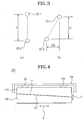
interval adjusting apparatus 20 as described above has a shortcoming in that the image formation by the two laser lines in the scanning direction starts at different positions. By way of example, Figure 39(a) shows two laser diodes 22-1, 22-2 that are aligned perpendicular to the scanning direction and separated by interval (p). Ideally, two lines are formed on thephotoreceptor drum 17 at the predetermined interval (p). If, however, the two lines are formed at an interval other than the predetermined interval (p), the deviation can be removed by adjusting the interval between the laser diodes. Accordingly, thesub-assembly plate 23 is rotated to correct the interval between the two lines. However, while the interval between the two laser diodes 22-1, 22-2 in the sub-scanning direction becomes p', the laser diodes 22-1, 22-2 deviate from their intended plane in the main scanning direction by a distance (Δ) (see Figure 3(b)). As a result, the image formation in the scanning direction starts differently. Such a problem can be solved by employing software or a device for compensation. - However, employment of the compensation software or device causes the structure of the laser scanning unit to be complex and more expensive to make.
- An image forming apparatus according to the present invention is characterised by moveable prism means located in the paths of said laser beams and configured such that the separation of the laser beams at the photoconductive latent image forming means can be controlled by movement of the prism means to compensate for convergence of the laser beams.
- Preferably, the prism means has a trapezoidal cross-section and the first laser beam passes through a thinner part of the prism means than the second laser beam. Consequently, it the beams are not perfectly parallel, the movement of the prism has a differential effect on the lengths of the paths of the beams through the prism means.
- Preferably, the scanning means includes a rotary polygonal mirror and the prism means is elongate in the scanning direction and located between the polygonal mirror and the photoconductive latent image forming means.
- Preferred and optional features of the present invention are also set out in
claims 1 to 50 appended hereto. - Embodiments of the present invention will now be described, by way of example, with reference to Figures 4 to 9 of the accompanying drawings, in which:
- Figure 1 shows the structure of a conventional scanning unit;
- Figure 2 is an exploded perspective view of an apparatus for adjusting the interval in a sub-scanning direction for a conventional multi-beam scanning unit;
- Figure 3(a) and 3(b) are views showing deviations in the starting point of image formation due to the interval adjusting apparatus of Figure 2;
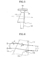
- Figure 4 shows an apparatus for adjusting the interval in a sub-scanning direction for a multi-beam scanning unit according to the present invention;
- Figure 5 is a side view of the interval adjusting apparatus of Figure 4;
- Figure 6 shows the change in the optical path of a laser beam passing through the interval adjusting apparatus of Figure 4;
- Figure 7A shows the changes in the optical paths of two parallel laser beams passing through the interval adjusting apparatus of Figure 4;
- Figure 7B shows the changes in the optical paths of two non-parallel laser beams passing through the interval adjusting apparatus of Figure 4;
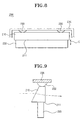
- Figure 8 shows another apparatus for adjusting the interval in the sub-scanning direction of a multi-beam scanning unit according to the present invention; and
- Figure 9 is a side view of the interval adjusting apparatus of Figure 8.
-
- Referring to Figures 4 and 5, a sub-scanning
interval adjusting apparatus 100 for a multi-beam scanning unit includes atransparent member 110, amovable member 120 and anelastic member 130. - The
transparent member 110 is made of a material, such as glass or plastics, through which a laser beam can pass. Thetransparent member 110 is generally formed by injection moulding. Thetransparent member 110 has a predetermined optical refractivity greater than 1. The cross-section of thetransparent member 110 becomes thinner with height, i.e. the direction (a sub-scanning direction as indicated by arrow C) perpendicular to a laser scanning direction as indicated by arrow B. - Figure 5 shows one example of a structure of the
transparent member 110 in section. In this example, the cross-section of thetransparent member 110 is a trapezium. Alternatively, thetransparent member 110 may be triangular in cross-section. Thetransparent member 110 has alower side 111 formed at a predetermined angle with respect to a lengthwise direction (arrow B), i.e. the scanning direction. - The
movable member 120 has anupper side 121 formed at an angle corresponding to the angle of thelower side 111 of thetransparent member 110. Theupper side 121 of themovable member 120 is slidable with respect to thelower side 111 of thetransparent member 110. Themovable member 120 is also provided with a driving unit (not shown) for moving themovable member 120 leftwards and rightwards, i.e. in the scanning direction (arrow B). Accordingly, as themovable member 120 is moved leftward and rightward, thetransparent member 110 is moved upward and downward (the arrow C). - The
elastic member 130 is placed on thetransparent member 110 and presses thetransparent member 110 against themovable member 120. Being secured in a certain position of aframe 135 of a scanning unit, theelastic member 130 also serves to secure thetransparent member 110 at a certain position in the path of the laser beam. Theelastic member 130 is made of any material that has resilience and a compression spring may be used as theelastic member 130. - The operation of the sub-scanning interval adjusting apparatus for the multi-beam scanning unit will now be described.
- When two laser beams are focused on a photoreceptor drum 17 (Figure 1) at an interval different from the intended interval, the
movable member 120 is moved leftward or rightward, i.e. in the scanning direction (arrow C), by driving the driving unit. If themovable member 120 is moved rightward, thetransparent member 110 is moved upward compressing theelastic member 130. If themovable member 120 is moved leftward, thetransparent member 110 is moved downward by theelastic member 130. As thetransparent member 110 is moved upwards and downwards with respect to the optical paths of the two laser beams, the optical paths are changed by thetransparent member 110, and as a result, the interval between the two laser lines can be adjusted. - The principle of adjusting the interval between the two laser lines using the upward and downward movement of the
transparent member 110 will now be described in greater detail. - Figure 6 illustrates a process in which the optical path of the laser beam incident on the
transparent member 110 changes as the laser beam passes through thetransparent member 110. The laser beam passing through thetransparent member 110 satisfies the following equation of the Snell's law.Equation 1transparent member 110, 1 is an angle of incidence of the laser beam on thetransparent member 110 with respect to anincident surface 110a of thetransparent member 110, and 2 is an angle of refraction of the laser beam entering thetransparent member 110. - In Figure 6, an upper laser beam of two laser beams from two laser diodes is indicated as
laser beam 1 ○, while a lower laser beam is indicated aslaser beam 2 ○. The interval between the twoincident laser beams 1 ○, 2 ○ is L. When the optical paths of the twolaser beams 1 ○, 2 ○ through thetransparent member 110c are the same length, the interval between them remains the same. However, when the optical paths of the twolaser beams 1 ○, 2 ○ through thetransparent member 110b have different lengths, as illustrated in Figure 6, the interval between the twolaser beams 1 ○, 2 ○ increases from L to L' by an amount corresponding the difference in path length. This is because of different optical distances of optical paths of the twolaser beams 1 ○, 2 ○ with respect to the aplane 110c parallel to theincident surface 110a oftransparent member 110, and anexit surface 110b. The optical distance is obtained by multiplying the refractive index n of a medium by the thickness d of the medium. - Even with a
transparent member 110 that is formed with a uniform thickness, a difference between the optical distances of the twolaser beams 1 ○, 2 ○ occurs if the upper and lower laser beams are not parallel relation to each other when they are incident on thetransparent member 110. - Figure 7A shows the situation where the incident laser beams are parallel. The upper laser beam is indicated by 1 ○ and the lower laser beam is indicated by 2 ○. The upper and
lower laser beams 1 ○, 2 ○ are separated by an interval L. With thetransparent member 110 at position, the
laser beams 1 ○, 2 ○ pass through thetransparent member 110 and exit respectively from points, . The interval between the exit laser beams is L'. Then when the
transparent member 110 is moved by the movable member downward to another position', the
laser beams 1 ○, 2 ○ pass through thetransparent member 110 and exit respectively from points', '. The interval between the exit laser beams is L'. The optical path of the two laser beams varies by p2p3 and p2'p3' depending on the position
 '. As noted from Figure 7A, a triangle p1p2p3 and another triangle p1'p2'p3' are congruent and, thus, the optical paths p2p3 and p2'p3' are identical in length. Accordingly, the interval L' between the two laser beams can be kept constant even when the thickness of the
transparent member 110 varies. - Figure 7B shows two non-parallel laser beams being incident on the
transparent member 110. The upper laser beam is indicated by 1 ○ while the lower laser beam is indicated by 2 ○. With thetransparent member 110 at the position, the upper and
lower laser beams 1 ○, 2 ○pass through thetransparent member 110 and exit respectively from the points © ,. The interval between the exit laser beams is M. Then when the
transparent member 110 is moved by the movable member downward to the position', the
laser beams 1 ○, 2 ○ pass through thetransparent member 110 and exit respectively from the points © ','. The interval between the exit laser beams is M'. The optical path of the two
laser beams 1 ○, 2 ○ varies by q2q3 and q2'q3' depending on the positioning of thetransparent member 110 in positionand position '. A triangle q1q2q3 and another triangle q1'q2'q3' are similar shaped but different sized. Accordingly, the optical paths q2q3 and q2'q3' are in the same proportion. That is, as the
transparent member 110 varies in thickness, the interval between the laser beams passing through thetransparent member 110 also varies. Accordingly, by varying thetransparent member 110 in thickness as described above, the interval between the two laser lines on the photoreceptor drum is adjusted to a desired value. - In another embodiment, the sub-scanning
interval adjusting apparatus 200 for the multi-beam scanning unit includes atransparent member 210, amovable member 220 and anelastic member 230. - The
transparent member 210 is made of a material, such as glass or plastics, through which a laser beam can pass. Thetransparent member 210 is generally formed by injection moulding. Thetransparent member 210 has a predetermined optical refractive index greater than 1. The cross-section of thetransparent member 210 varies in thickness with height (sub-scanning direction; arrow C). - Referring to Figure 9, the cross-section of the
transparent member 210 is a trapezium. Alternatively, thetransparent member 210 may be triangular in cross-section. - The
movable member 220 is formed so as to bear against alower side 211 of thetransparent member 210 and is provided with a driving unit (not shown) for moving it upwards and downwards, i.e. in the sub-scanning direction (arrow C). Accordingly, as themovable member 220 is moved upwards and downwards, thetransparent member 210 is moved upwards and downwards (the arrow C). The driving unit may be any suitable device that can reciprocate themovable member 220 linearly accurately. For example, a precision screw device can be used as the driving unit. - The
elastic member 230 is placed on thetransparent member 210 and presses thetransparent member 210 against themovable member 220. Being secured in a certain position of aframe 235 of a scanning unit, theelastic member 230 also serves to secure thetransparent member 210 at a certain position in an optical paths of the laser beams. Theelastic member 230 is made of any material that has a resilience and a compression spring can be used for theelastic member 130. - The operation of the sub-scanning
interval adjusting apparatus 200 for the multi-beam scanning unit having the above structure, will now be described. - When two laser lines are concentrated on a photoreceptor drum 17 (Figure 1) at an interval deviated from a predetermined laser line interval, the
movable member 220 is moved upwards or downwards, i.e. in the sub-scanning direction, by driving the driving unit. If themovable member 120 is moved downwards, thetransparent member 210 is moved downward smoothly by theelastic member 230. As thetransparent member 210 is moved upwards and downwards, the lengths of the optical paths through thetransparent member 210 change by and as a result, the interval between the two laser lines is changed. - In accordance with the present invention as described above, the interval between the two laser beams can be adjusted with ease, and without varying starting positions of the image formation of the laser beams in the scanning direction.
Claims (54)
- A sub-scanning interval adjusting apparatus adjusting an interval between at least two laser beams for a multi-beam scanning unit, the at least two laser beams being simultaneously emitted from at least two laser sources of the multi-beam scanning unit, the apparatus comprising:a transparent member arranged on an optical path of the at least two laser beams to adjust the interval between the at least two laser beams.
- The sub-scanning interval adjusting apparatus of claim 1, wherein the transparent member has a thickness varying depending on a height thereof perpendicular to a direction where the at least two laser beams pass through.
- The sub-scanning interval adjusting apparatus of claim 2, wherein the transparent member comprises:a triangular shape in cross-section in the direction where the at least two laser beams pass through.
- The sub-scanning interval adjusting apparatus of claim 2, wherein the transparent member comprises:a trapezoidal shape in cross-section in the direction where the at least two laser beams pass through.
- A sub-scanning interval adjusting apparatus adjusting an interval between at least two laser beams for a multi-beam scanning unit, the laser beams being simultaneously emitted from at least two laser sources of the multi-beam scanning unit, the apparatus comprising:wherein the interval between the at least two laser beams is adjusted by varying the height of the transparent member with respect to the at least two laser sources with the movable member.a transparent member having a thickness varying depending on a height thereof perpendicular to a direction where the at least two laser beams pass through; anda movable member moving the transparent member in a height direction of the transparent member,
- The sub-scanning interval adjusting apparatus of claim 5, wherein the transparent member comprises:a triangular shape in cross-section in the direction where the at least two laser beams pass through.
- The sub-scanning interval adjusting apparatus of claim 5, wherein the transparent member comprises:a trapezoidal shape in cross-section in the direction where the at least two laser beams pass through.
- The sub-scanning interval adjusting apparatus of claim 5, wherein the transparent member has an optical refractivity equal to or great than 1.
- The sub-scanning interval adjusting apparatus of claim 5, further comprising:an elastic member pressing the transparent member against the movable member.
- The sub-scanning interval adjusting apparatus of claim 5, wherein the transparent member is made either of glass or plastic by injection molding.
- A sub-scanning interval adjusting apparatus adjusting an interval between at least two laser beams for a multi beam scanning unit, the laser beams being simultaneously emitted from at least two laser sources of the multi-beam scanning unit, the apparatus comprising:wherein the interval between the at least two laser beams is adjusted by moving the movable member towards the scanning direction and thus varying a height of the transparent member with respect to the at least two laser sources.a transparent member having a thickness varying depending on a height thereof perpendicular to a direction where the at least two laser beams pass through, and having an inclined lower side inclined with respect to a scanning direction of the at least two laser beams; anda movable member having an inclined side corresponding to the inclined lower side of the transparent member,
- The sub-scanning interval adjusting apparatus of claim 11, wherein the transparent member comprises:a triangular shape in cross-section in the direction where the at least two laser beams pass through.
- The sub-scanning interval adjusting apparatus of claim 11, wherein the transparent member comprises:a trapezoidal shape in cross-section in the direction where the at least two laser beams pass through.
- The sub-scanning interval adjusting apparatus of claim 11, wherein the transparent member has an optical refractivity equal to or greater than 1.
- The sub-scanning interval adjusting apparatus of claim 11, further comprising:an elastic member pressing the transparent member with respect to the movable member.
- The sub-scanning interval adjusting apparatus of claim 11, wherein the transparent member is made either of glass or plastic by injection molding.
- A multi-beam scanning unit for simultaneously emitting at least two laser beams by using at least two laser sources, the multi-beam scanning unit comprising:wherein the interval between the at least two laser beams is adjusted by moving the movable member toward the scanning direction, and a height of the transparent member with respect to the laser source varies.a sub-scanning interval adjusting apparatus comprising,a transparent member having a thickness varying depending on a height thereof perpendicular to a direction where the at least two laser beams pass through, the transparent member having an inclined lower side inclined with respect to a scanning direction of the at least two laser beams, anda movable member having an inclined side corresponding to the inclined lower side of the transparent member,
- The multi-beam scanning unit of claim 17, further comprising:an elastic member formed on the transparent member to press the transparent member with respect to the movable member.
- A sub-scanning interval adjusting apparatus adjusting an interval between first and second laser beams in a multi-beam scanning unit, the apparatus comprising:first and second laser diodes emitting the first and second two laser beams along first and second optical paths, which are spaced-apart from each other, respectively; anda transparent member disposed on the first and second optical paths of the first and second laser beams, and having a first thickness corresponding to the first optical path of the first laser beam and a second thickness corresponding to the second optical path of the second laser beam in an optical path direction of the first and second optical paths; anda moving member controlling the transparent member to adjust the first thickness and the second thickness of the transparent member to adjust the interval between the first and second laser beams.
- The sub-scanning interval adjusting apparatus of claim 19, wherein the first and second laser diodes simultaneously emit the first and second two laser beams toward the transparent member.
- The sub-scanning interval adjusting apparatus of claim 19, wherein the first and second laser diodes simultaneously emit the first and second two laser beams parallel to each other by an initial interval which is changed to the interval by the transparent member.
- The sub-scanning interval adjusting apparatus of claim 19, wherein the moving member moves the transparent member in a direction perpendicular to a line passing through the first and second optical paths to change the first thickness and the second thickness, and the first and second laser diodes are disposed in the direction perpendicular to the line passing through the first and second optical paths.
- The sub-scanning interval adjusting apparatus of claim 19, wherein the first and second two laser beams form an initial interval in a direction perpendicular to the optical path direction of the first and second optical paths when being incident to the transparent member and form the interval greater than the initial interval when exiting the transparent member.
- The sub-scanning interval adjusting apparatus of claim 19, wherein the first thickness and the second thickness of the transparent member are not the same.
- The sub-scanning interval adjusting apparatus of claim 19, wherein the first thickness and the second thickness simultaneously increase or decrease when the moving member moves the transparent member in a direction having an angle with the optical path direction of the first and second optical paths.
- The sub-scanning interval adjusting apparatus of claim 19, further comprising:a frame on which the transparent member is movably disposed.
- The sub-scanning interval adjusting apparatus of claim 26, further comprising:an elastic member coupled between the transparent member and the frame to bias the transparent member with respect to the frame.
- The sub-scanning interval adjusting apparatus of claim 27, wherein the moving member is disposed opposite to the elastic member with respect to the transparent member to move the transparent member with respect to the frame and the elastic member.
- The sub-scanning interval adjusting apparatus of claim 27, wherein the frame, the transparent member, and the moving member are disposed in a direction perpendicular to the optical path direction.
- The sub-scanning interval adjusting apparatus of claim 27, further comprising:a driving unit moving the moving member to move the transparent member in a direction having an angle with the optical path direction.
- The sub-scanning interval adjusting apparatus of claim 26, wherein:the transparent member comprises,
a first inclined surface inclined with respect to the first and second optical paths; and
the moving member comprises,
a second inclined surface corresponding to the first inclined surface of the transparent member. - The sub-scanning interval adjusting apparatus of claim 31, wherein the first inclined surface and the second inclined surface are disposed in a direction having an angle with the optical path direction of the first and second optical paths.
- The sub-scanning interval adjusting apparatus of claim 31, wherein the transparent member moves in a direction perpendicular to the optical path direction when the moving member moves in the optical path direction.
- The sub-scanning interval adjusting apparatus of claim 31, wherein the first inclined surface of the transparent member slides along the second surface of the moving member in a direction having an angle with the optical path direction.
- The sub-scanning interval adjusting apparatus of claim 19, wherein the transparent member narrows in a direction having an angle with the optical path direction.
- The sub-scanning interval adjusting apparatus of claim 19, wherein the transparent member moves in a direction having an angle with the optical path direction to change the first thickness and the second thickness in response to a movement of the moving member.
- The sub-scanning interval adjusting apparatus of claim 19, wherein the transparent member comprises:incident and exit surfaces disposed on the first and second optical paths to be spaced-apart from each other by a variable thickness including the first thickness and the second thickness.
- A sub-scanning interval adjusting apparatus adjusting an interval between first and second laser beams in a multi-beam scanning unit, the apparatus comprising:first and second laser diodes simultaneously emitting the first and second laser beams along first and second optical paths, which are spaced-apart from each other, respectively; anda transparent member disposed on the first and second optical paths of the first and second laser beams, and narrowing in a direction having an angle with an optical path direction of the first and second optical paths; anda moving member moving the transparent member to adjust the interval between the first and second laser beams.
- A multi-beam scanning unit for adjusting an interval between two laser beams, the multi-beam scanning unit comprising:a sub-scanning interval adjusting apparatus having first and second laser diodes emitting the first and second two laser beams along first and second optical paths, which are spaced-apart from each other, respectively, a transparent member disposed on the first and second optical paths of the first and second laser beams to narrow in a direction having an angle with an optical path direction of the first and second optical paths, and a moving member moving the transparent member to adjust the interval between the first and second laser beams, andfirst and second photoreceptor drums on which the first and second laser beams form first and second scan lines spaced-apart from each other by a distance corresponding to the interval.
- The multi-beam scanning unit of claim 39, further comprising:a polygon mirror disposed between the sub-scanning interval adjusting apparatus and the first and second photoreceptor drums to direct the first and second laser beams toward the first and second photoreceptor drums, respectively.
- The multi-beam scanning unit of claim 40, further comprising:an f- lens disposed between the polygon mirror and the first and second photoreceptor drums to focus the first and second laser beams on the first and second photoreceptor drums.
- The multi-beam scanning unit of claim 39, wherein the first and second laser diodes simultaneously emit the first and second two laser beams, respectively, and the first and second scanning lines are simultaneously formed on the first and second photoreceptor drums.
- The multi-beam scanning unit of claim 39, wherein the first and second scanning lines are formed in a scanning direction, and the first and second scanning lines are spaced- apart from each other in a sub-scanning direction perpendicular to the scanning direction.
- The multi-beam scanning unit of claim 39, wherein the first scanning line is formed on the first photoreceptor drum, and the second scanning line is formed on the second photoreceptor drum which is spaced-apart from the first photoreceptor drum.
- The multi-beam scanning unit of claim 39, wherein the first and second photoreceptor drums are spaced-apart from each other by a length which is not variable, and the first and second scanning lines simultaneously formed on the first and second photoreceptor drums, respectively, are spaced-apart from each other by another distance, which is variable according to adjustment of the interval of the first and second laser beams.
- The multi-beam scanning unit of claim 45, wherein the interval between the first and second laser beams is variable according to a movement of the transparent member.
- The multi-beam scanning unit of claim 39, wherein the transparent member comprises:a first thickness corresponding to the first optical path of the first laser beam in the optical path direction; anda second thickness corresponding to the second optical path of the second laser beam in the optical path direction.
- The multi-beam scanning unit of claim 39, wherein the first scanning line of the first laser beam has a first starting point of the photoreceptor corresponding to a reference point, and the second scanning line of the second laser beam has a second starting point corresponding to the reference point.
- The multi-beam scanning unit of claim 39, wherein the first and second optical paths are disposed to be parallel in the direction perpendicular to the optical path direction of the first and second optical paths
- The multi-beam scanning unit of claim 39, wherein the first and second start points of the first and second scanning lines do not vary when the distance of the first and second scanning lines varies according to adjustment of the interval of the first and second laser beams.
- A multi-beam laser image forming apparatus comprising a source (22-1, 22-2) of first and second substantially parallel laser beams, photoconductive latent image forming means (17) and scanning means (13, 15, 16) for scanning the laser beams from said source (22-1, 22-2) substantially in parallel over the photoconductive latent image forming means (17), characterised by moveable prism means (110; 210) located in the paths of said laser beams and configured such that the separation (M, M') of the laser beams at the photoconductive latent image forming means (17) can be controlled by movement of the prism means to compensate for convergence of the laser beams.
- An apparatus according to claim 51, wherein the prism means (110; 210) has a trapezoidal cross-section and the first laser beam passes through a thinner part of the prism means than the second laser beam.
- An apparatus according to claim 52, wherein the prism means (110; 210) is moveable such that the paths of the laser beams through the prism means (110; 210) can be increased and decreased thereby.
- An apparatus according to claim 51, 52 or 53, wherein the scanning means (13, 15, 16) includes a rotary polygonal mirror (13) and the prism means (110; 210) is elongate in the scanning direction and located between the polygonal mirror (13) and the photoconductive latent image forming means (17).
Applications Claiming Priority (2)
| Application Number | Priority Date | Filing Date | Title |
|---|---|---|---|
| KR10-2002-0049961A KR100452854B1 (en) | 2002-08-23 | 2002-08-23 | Apparatus for adjusting a distance between beams of multi-beam laser scanning unit |
| KR2002049961 | 2002-08-23 |
Publications (2)
| Publication Number | Publication Date |
|---|---|
| EP1391770A1 true EP1391770A1 (en) | 2004-02-25 |
| EP1391770B1 EP1391770B1 (en) | 2005-12-14 |
Family
ID=36590865
Family Applications (1)
| Application Number | Title | Priority Date | Filing Date |
|---|---|---|---|
| EP03253569A Expired - Lifetime EP1391770B1 (en) | 2002-08-23 | 2003-06-05 | Sub-scanning interval adjusting device for multi-beam image forming apparatus |
Country Status (5)
| Country | Link |
|---|---|
| US (1) | US7050083B2 (en) |
| EP (1) | EP1391770B1 (en) |
| KR (1) | KR100452854B1 (en) |
| CN (1) | CN100405123C (en) |
| DE (1) | DE60302729T2 (en) |
Families Citing this family (16)
| Publication number | Priority date | Publication date | Assignee | Title |
|---|---|---|---|---|
| US7151556B2 (en) * | 2002-08-23 | 2006-12-19 | Samsung Electronics Co., Ltd. | Sub-scanning interval adjusting apparatus for multi-beam scanning unit |
| US9983559B2 (en) * | 2002-10-22 | 2018-05-29 | Fisher-Rosemount Systems, Inc. | Updating and utilizing dynamic process simulation in an operating process environment |
| US7729789B2 (en) | 2004-05-04 | 2010-06-01 | Fisher-Rosemount Systems, Inc. | Process plant monitoring based on multivariate statistical analysis and on-line process simulation |
| JP2007536634A (en) | 2004-05-04 | 2007-12-13 | フィッシャー−ローズマウント・システムズ・インコーポレーテッド | Service-oriented architecture for process control systems |
| US20060017795A1 (en) * | 2004-07-26 | 2006-01-26 | Seiko Epson Corporation | Image forming apparatus, image forming method and data control device |
| KR100580200B1 (en) | 2004-10-19 | 2006-05-16 | 삼성전자주식회사 | Optical scanner assembly, electrophotographic image forming apparatus having the same, and scanning line skew adjusting method |
| US8055358B2 (en) | 2005-12-05 | 2011-11-08 | Fisher-Rosemount Systems, Inc. | Multi-objective predictive process optimization with concurrent process simulation |
| JP4650526B2 (en) * | 2008-06-25 | 2011-03-16 | 富士ゼロックス株式会社 | Optical scanning device |
| US8881039B2 (en) | 2009-03-13 | 2014-11-04 | Fisher-Rosemount Systems, Inc. | Scaling composite shapes for a graphical human-machine interface |
| US8825183B2 (en) | 2010-03-22 | 2014-09-02 | Fisher-Rosemount Systems, Inc. | Methods for a data driven interface based on relationships between process control tags |
| US8602790B1 (en) * | 2010-06-04 | 2013-12-10 | Museum of Mathematics | Demonstration tools for geometric properties |
| CN103676971B (en) * | 2013-12-03 | 2016-03-16 | 上海卫星装备研究所 | VUV Irradiation strength control device and control method |
| JP6319207B2 (en) * | 2015-06-30 | 2018-05-09 | 京セラドキュメントソリューションズ株式会社 | Optical scanning device and image forming apparatus using the same |
| US10878140B2 (en) | 2016-07-27 | 2020-12-29 | Emerson Process Management Power & Water Solutions, Inc. | Plant builder system with integrated simulation and control system configuration |
| US11418969B2 (en) | 2021-01-15 | 2022-08-16 | Fisher-Rosemount Systems, Inc. | Suggestive device connectivity planning |
| CN117389030A (en) * | 2022-07-04 | 2024-01-12 | 西安炬光科技股份有限公司 | Beam scanning system and scanning method |
Citations (6)
| Publication number | Priority date | Publication date | Assignee | Title |
|---|---|---|---|---|
| US4878066A (en) * | 1987-09-18 | 1989-10-31 | Kabushiki Kaisha Toshiba | Beam scanner with distortion correction |
| JPH03168715A (en) * | 1989-11-29 | 1991-07-22 | Ricoh Kogaku Kk | Image forming lens holding device of optical scanning device |
| EP0703088A2 (en) * | 1994-08-29 | 1996-03-27 | Konica Corporation | Image forming apparatus having a two-beam optical scanning unit |
| US5818496A (en) * | 1994-07-14 | 1998-10-06 | Hitachi Koki Co., Ltd. | Exposure device of electrophotographic apparatus with optical path position deciding device |
| US5844591A (en) * | 1994-09-08 | 1998-12-01 | Fuji Xerox Co., Ltd. | Multibeam laser recording apparatus |
| JP2002174785A (en) * | 2000-12-08 | 2002-06-21 | Ricoh Opt Ind Co Ltd | Light beam regulation method for multibeam scanner as well as multibeam scanner and image forming device |
Family Cites Families (10)
| Publication number | Priority date | Publication date | Assignee | Title |
|---|---|---|---|---|
| JPS59202449A (en) * | 1983-05-02 | 1984-11-16 | Canon Inc | Copy machine |
| US5210635A (en) * | 1989-04-17 | 1993-05-11 | Dainippon Screen Mfg. Co., Ltd. | Multibeam scanning system |
| JP3463054B2 (en) * | 1996-01-19 | 2003-11-05 | 株式会社エヌ・イー・エフ | Multi-beam scanner |
| JPH09251137A (en) * | 1996-03-15 | 1997-09-22 | Konica Corp | Laser recorder |
| JPH10115789A (en) * | 1996-10-11 | 1998-05-06 | Ricoh Co Ltd | Multi-beam recorder |
| US6038076A (en) * | 1997-12-03 | 2000-03-14 | Noran Instruments, Inc. | Wavelength selection, multiplexing and demultiplexing method and apparatus |
| JPH11212008A (en) * | 1998-01-22 | 1999-08-06 | Toshiba Corp | Optical scanning device, image forming device, and optical axis adjusting device of optical scanning device |
| JP3913357B2 (en) * | 1998-03-25 | 2007-05-09 | 株式会社リコー | Multi-beam optical scanning device and image forming apparatus |
| JP2001337283A (en) * | 2000-05-25 | 2001-12-07 | Ricoh Co Ltd | Laser beam scanning device |
| JP3881842B2 (en) * | 2000-12-05 | 2007-02-14 | 株式会社ジェイテクト | Variable displacement pump |
-
2002
- 2002-08-23 KR KR10-2002-0049961A patent/KR100452854B1/en not_active Expired - Fee Related
-
2003
- 2003-05-14 US US10/437,185 patent/US7050083B2/en not_active Expired - Fee Related
- 2003-06-05 EP EP03253569A patent/EP1391770B1/en not_active Expired - Lifetime
- 2003-06-05 DE DE60302729T patent/DE60302729T2/en not_active Expired - Fee Related
- 2003-08-22 CN CNB031543979A patent/CN100405123C/en not_active Expired - Fee Related
Patent Citations (6)
| Publication number | Priority date | Publication date | Assignee | Title |
|---|---|---|---|---|
| US4878066A (en) * | 1987-09-18 | 1989-10-31 | Kabushiki Kaisha Toshiba | Beam scanner with distortion correction |
| JPH03168715A (en) * | 1989-11-29 | 1991-07-22 | Ricoh Kogaku Kk | Image forming lens holding device of optical scanning device |
| US5818496A (en) * | 1994-07-14 | 1998-10-06 | Hitachi Koki Co., Ltd. | Exposure device of electrophotographic apparatus with optical path position deciding device |
| EP0703088A2 (en) * | 1994-08-29 | 1996-03-27 | Konica Corporation | Image forming apparatus having a two-beam optical scanning unit |
| US5844591A (en) * | 1994-09-08 | 1998-12-01 | Fuji Xerox Co., Ltd. | Multibeam laser recording apparatus |
| JP2002174785A (en) * | 2000-12-08 | 2002-06-21 | Ricoh Opt Ind Co Ltd | Light beam regulation method for multibeam scanner as well as multibeam scanner and image forming device |
Non-Patent Citations (2)
| Title |
|---|
| DATABASE WPI Section PQ Week 200263, Derwent World Patents Index; Class P75, AN 2002-586717, XP002256307 * |
| PATENT ABSTRACTS OF JAPAN vol. 015, no. 415 (P - 1265) 22 October 1991 (1991-10-22) * |
Also Published As
| Publication number | Publication date |
|---|---|
| DE60302729D1 (en) | 2006-01-19 |
| KR20040018588A (en) | 2004-03-04 |
| KR100452854B1 (en) | 2004-10-14 |
| US20040036760A1 (en) | 2004-02-26 |
| CN1485645A (en) | 2004-03-31 |
| CN100405123C (en) | 2008-07-23 |
| DE60302729T2 (en) | 2006-07-06 |
| EP1391770B1 (en) | 2005-12-14 |
| US7050083B2 (en) | 2006-05-23 |
Similar Documents
| Publication | Publication Date | Title |
|---|---|---|
| EP1391770B1 (en) | Sub-scanning interval adjusting device for multi-beam image forming apparatus | |
| US6621512B2 (en) | Multi-beam light source device and multi-beam scanning apparatus using the same | |
| US7826116B2 (en) | Optical scanning device and image forming apparatus | |
| JP5074781B2 (en) | Optical scanning device | |
| US6600504B2 (en) | Image forming apparatus having light beam adjusting mechanism | |
| KR100644668B1 (en) | Mirror support device and optical scanning device having same | |
| US6844892B2 (en) | Multi-beam scanning device | |
| JP2004287380A (en) | Optical scanning device, scanning line correction method, scanning line correction control method, image forming apparatus, and image forming method | |
| US7372015B2 (en) | Beam detector and light scanner unit having the same | |
| US6731418B2 (en) | Multibeam scanning optical system and image forming apparatus using the same | |
| US6657760B2 (en) | Image scanning apparatus | |
| US7151556B2 (en) | Sub-scanning interval adjusting apparatus for multi-beam scanning unit | |
| US6816292B2 (en) | Scanning optical system | |
| US6731417B2 (en) | Scanning optical system | |
| JP4590111B2 (en) | Optical scanning device and image forming apparatus having the same | |
| US20150124039A1 (en) | Scan-line adjusting device, optical scanning device, and image forming apparatus | |
| KR100412495B1 (en) | multi-beam laser scanning apparatus | |
| US20210302721A1 (en) | Optical scanning apparatus | |
| JP2002258187A (en) | Image forming device | |
| JP2006145816A (en) | Optical scanning apparatus and image forming apparatus | |
| JPH05127106A (en) | Laser beam scanning optical device | |
| JP2006184548A (en) | Optical scanner | |
| JP2008233160A (en) | Optical device, optical scanning device, and image forming apparatus | |
| JPH09159954A (en) | Optical scanning device | |
| JPH0746385A (en) | Beam scanning device |
Legal Events
| Date | Code | Title | Description |
|---|---|---|---|
| PUAI | Public reference made under article 153(3) epc to a published international application that has entered the european phase |
Free format text: ORIGINAL CODE: 0009012 |
|
| AK | Designated contracting states |
Kind code of ref document: A1 Designated state(s): AT BE BG CH CY CZ DE DK EE ES FI FR GB GR HU IE IT LI LU MC NL PT RO SE SI SK TR |
|
| AX | Request for extension of the european patent |
Extension state: AL LT LV MK |
|
| 17P | Request for examination filed |
Effective date: 20040329 |
|
| 17Q | First examination report despatched |
Effective date: 20040611 |
|
| RAP1 | Party data changed (applicant data changed or rights of an application transferred) |
Owner name: SAMSUNG ELECTRONICS CO., LTD. |
|
| AKX | Designation fees paid |
Designated state(s): DE FR GB NL |
|
| GRAP | Despatch of communication of intention to grant a patent |
Free format text: ORIGINAL CODE: EPIDOSNIGR1 |
|
| GRAS | Grant fee paid |
Free format text: ORIGINAL CODE: EPIDOSNIGR3 |
|
| GRAA | (expected) grant |
Free format text: ORIGINAL CODE: 0009210 |
|
| AK | Designated contracting states |
Kind code of ref document: B1 Designated state(s): DE FR GB NL |
|
| REG | Reference to a national code |
Ref country code: GB Ref legal event code: FG4D |
|
| REF | Corresponds to: |
Ref document number: 60302729 Country of ref document: DE Date of ref document: 20060119 Kind code of ref document: P |
|
| ET | Fr: translation filed | ||
| PLBE | No opposition filed within time limit |
Free format text: ORIGINAL CODE: 0009261 |
|
| STAA | Information on the status of an ep patent application or granted ep patent |
Free format text: STATUS: NO OPPOSITION FILED WITHIN TIME LIMIT |
|
| 26N | No opposition filed |
Effective date: 20060915 |
|
| PG25 | Lapsed in a contracting state [announced via postgrant information from national office to epo] |
Ref country code: DE Free format text: LAPSE BECAUSE OF NON-PAYMENT OF DUE FEES Effective date: 20070103 |
|
| PGRI | Patent reinstated in contracting state [announced from national office to epo] |
Ref country code: DE Effective date: 20080218 |
|
| PGFP | Annual fee paid to national office [announced via postgrant information from national office to epo] |
Ref country code: NL Payment date: 20090603 Year of fee payment: 7 |
|
| PGFP | Annual fee paid to national office [announced via postgrant information from national office to epo] |
Ref country code: DE Payment date: 20090529 Year of fee payment: 7 Ref country code: GB Payment date: 20090603 Year of fee payment: 7 |
|
| REG | Reference to a national code |
Ref country code: NL Ref legal event code: V1 Effective date: 20110101 |
|
| GBPC | Gb: european patent ceased through non-payment of renewal fee |
Effective date: 20100605 |
|
| REG | Reference to a national code |
Ref country code: FR Ref legal event code: ST Effective date: 20110228 |
|
| PG25 | Lapsed in a contracting state [announced via postgrant information from national office to epo] |
Ref country code: DE Free format text: LAPSE BECAUSE OF NON-PAYMENT OF DUE FEES Effective date: 20110101 |
|
| PG25 | Lapsed in a contracting state [announced via postgrant information from national office to epo] |
Ref country code: FR Free format text: LAPSE BECAUSE OF NON-PAYMENT OF DUE FEES Effective date: 20100630 Ref country code: NL Free format text: LAPSE BECAUSE OF NON-PAYMENT OF DUE FEES Effective date: 20110101 |
|
| PG25 | Lapsed in a contracting state [announced via postgrant information from national office to epo] |
Ref country code: GB Free format text: LAPSE BECAUSE OF NON-PAYMENT OF DUE FEES Effective date: 20100605 |
|
| PGFP | Annual fee paid to national office [announced via postgrant information from national office to epo] |
Ref country code: FR Payment date: 20090611 Year of fee payment: 7 |