EP1391669A2 - Plant and method for producing liquefied natural gas and recovering carbon dioxide contained in natural gas and in a combustion exhaust gas - Google Patents
Plant and method for producing liquefied natural gas and recovering carbon dioxide contained in natural gas and in a combustion exhaust gas Download PDFInfo
- Publication number
- EP1391669A2 EP1391669A2 EP03292057A EP03292057A EP1391669A2 EP 1391669 A2 EP1391669 A2 EP 1391669A2 EP 03292057 A EP03292057 A EP 03292057A EP 03292057 A EP03292057 A EP 03292057A EP 1391669 A2 EP1391669 A2 EP 1391669A2
- Authority
- EP
- European Patent Office
- Prior art keywords
- carbon dioxide
- natural gas
- recovery apparatus
- combustion exhaust
- absorbing
- Prior art date
- Legal status (The legal status is an assumption and is not a legal conclusion. Google has not performed a legal analysis and makes no representation as to the accuracy of the status listed.)
- Granted
Links
Images

Classifications
-
- B—PERFORMING OPERATIONS; TRANSPORTING
- B01—PHYSICAL OR CHEMICAL PROCESSES OR APPARATUS IN GENERAL
- B01D—SEPARATION
- B01D53/00—Separation of gases or vapours; Recovering vapours of volatile solvents from gases; Chemical or biological purification of waste gases, e.g. engine exhaust gases, smoke, fumes, flue gases, aerosols
- B01D53/14—Separation of gases or vapours; Recovering vapours of volatile solvents from gases; Chemical or biological purification of waste gases, e.g. engine exhaust gases, smoke, fumes, flue gases, aerosols by absorption
- B01D53/1456—Removing acid components
- B01D53/1475—Removing carbon dioxide
-
- C—CHEMISTRY; METALLURGY
- C01—INORGANIC CHEMISTRY
- C01B—NON-METALLIC ELEMENTS; COMPOUNDS THEREOF; METALLOIDS OR COMPOUNDS THEREOF NOT COVERED BY SUBCLASS C01C
- C01B32/00—Carbon; Compounds thereof
- C01B32/50—Carbon dioxide
-
- F—MECHANICAL ENGINEERING; LIGHTING; HEATING; WEAPONS; BLASTING
- F25—REFRIGERATION OR COOLING; COMBINED HEATING AND REFRIGERATION SYSTEMS; HEAT PUMP SYSTEMS; MANUFACTURE OR STORAGE OF ICE; LIQUEFACTION SOLIDIFICATION OF GASES
- F25J—LIQUEFACTION, SOLIDIFICATION OR SEPARATION OF GASES OR GASEOUS OR LIQUEFIED GASEOUS MIXTURES BY PRESSURE AND COLD TREATMENT OR BY BRINGING THEM INTO THE SUPERCRITICAL STATE
- F25J1/00—Processes or apparatus for liquefying or solidifying gases or gaseous mixtures
- F25J1/0002—Processes or apparatus for liquefying or solidifying gases or gaseous mixtures characterised by the fluid to be liquefied
- F25J1/0022—Hydrocarbons, e.g. natural gas
-
- F—MECHANICAL ENGINEERING; LIGHTING; HEATING; WEAPONS; BLASTING
- F25—REFRIGERATION OR COOLING; COMBINED HEATING AND REFRIGERATION SYSTEMS; HEAT PUMP SYSTEMS; MANUFACTURE OR STORAGE OF ICE; LIQUEFACTION SOLIDIFICATION OF GASES
- F25J—LIQUEFACTION, SOLIDIFICATION OR SEPARATION OF GASES OR GASEOUS OR LIQUEFIED GASEOUS MIXTURES BY PRESSURE AND COLD TREATMENT OR BY BRINGING THEM INTO THE SUPERCRITICAL STATE
- F25J1/00—Processes or apparatus for liquefying or solidifying gases or gaseous mixtures
- F25J1/02—Processes or apparatus for liquefying or solidifying gases or gaseous mixtures requiring the use of refrigeration, e.g. of helium or hydrogen ; Details and kind of the refrigeration system used; Integration with other units or processes; Controlling aspects of the process
- F25J1/0243—Start-up or control of the process; Details of the apparatus used; Details of the refrigerant compression system used
- F25J1/0279—Compression of refrigerant or internal recycle fluid, e.g. kind of compressor, accumulator, suction drum etc.
- F25J1/0281—Compression of refrigerant or internal recycle fluid, e.g. kind of compressor, accumulator, suction drum etc. characterised by the type of prime driver, e.g. hot gas expander
- F25J1/0282—Steam turbine as the prime mechanical driver
-
- F—MECHANICAL ENGINEERING; LIGHTING; HEATING; WEAPONS; BLASTING
- F25—REFRIGERATION OR COOLING; COMBINED HEATING AND REFRIGERATION SYSTEMS; HEAT PUMP SYSTEMS; MANUFACTURE OR STORAGE OF ICE; LIQUEFACTION SOLIDIFICATION OF GASES
- F25J—LIQUEFACTION, SOLIDIFICATION OR SEPARATION OF GASES OR GASEOUS OR LIQUEFIED GASEOUS MIXTURES BY PRESSURE AND COLD TREATMENT OR BY BRINGING THEM INTO THE SUPERCRITICAL STATE
- F25J3/00—Processes or apparatus for separating the constituents of gaseous or liquefied gaseous mixtures involving the use of liquefaction or solidification
- F25J3/02—Processes or apparatus for separating the constituents of gaseous or liquefied gaseous mixtures involving the use of liquefaction or solidification by rectification, i.e. by continuous interchange of heat and material between a vapour stream and a liquid stream
- F25J3/0204—Processes or apparatus for separating the constituents of gaseous or liquefied gaseous mixtures involving the use of liquefaction or solidification by rectification, i.e. by continuous interchange of heat and material between a vapour stream and a liquid stream characterised by the feed stream
- F25J3/0209—Natural gas or substitute natural gas
-
- F—MECHANICAL ENGINEERING; LIGHTING; HEATING; WEAPONS; BLASTING
- F25—REFRIGERATION OR COOLING; COMBINED HEATING AND REFRIGERATION SYSTEMS; HEAT PUMP SYSTEMS; MANUFACTURE OR STORAGE OF ICE; LIQUEFACTION SOLIDIFICATION OF GASES
- F25J—LIQUEFACTION, SOLIDIFICATION OR SEPARATION OF GASES OR GASEOUS OR LIQUEFIED GASEOUS MIXTURES BY PRESSURE AND COLD TREATMENT OR BY BRINGING THEM INTO THE SUPERCRITICAL STATE
- F25J3/00—Processes or apparatus for separating the constituents of gaseous or liquefied gaseous mixtures involving the use of liquefaction or solidification
- F25J3/02—Processes or apparatus for separating the constituents of gaseous or liquefied gaseous mixtures involving the use of liquefaction or solidification by rectification, i.e. by continuous interchange of heat and material between a vapour stream and a liquid stream
- F25J3/0228—Processes or apparatus for separating the constituents of gaseous or liquefied gaseous mixtures involving the use of liquefaction or solidification by rectification, i.e. by continuous interchange of heat and material between a vapour stream and a liquid stream characterised by the separated product stream
- F25J3/0266—Processes or apparatus for separating the constituents of gaseous or liquefied gaseous mixtures involving the use of liquefaction or solidification by rectification, i.e. by continuous interchange of heat and material between a vapour stream and a liquid stream characterised by the separated product stream separation of carbon dioxide
-
- F—MECHANICAL ENGINEERING; LIGHTING; HEATING; WEAPONS; BLASTING
- F25—REFRIGERATION OR COOLING; COMBINED HEATING AND REFRIGERATION SYSTEMS; HEAT PUMP SYSTEMS; MANUFACTURE OR STORAGE OF ICE; LIQUEFACTION SOLIDIFICATION OF GASES
- F25J—LIQUEFACTION, SOLIDIFICATION OR SEPARATION OF GASES OR GASEOUS OR LIQUEFIED GASEOUS MIXTURES BY PRESSURE AND COLD TREATMENT OR BY BRINGING THEM INTO THE SUPERCRITICAL STATE
- F25J2205/00—Processes or apparatus using other separation and/or other processing means
- F25J2205/50—Processes or apparatus using other separation and/or other processing means using absorption, i.e. with selective solvents or lean oil, heavier CnHm and including generally a regeneration step for the solvent or lean oil
-
- F—MECHANICAL ENGINEERING; LIGHTING; HEATING; WEAPONS; BLASTING
- F25—REFRIGERATION OR COOLING; COMBINED HEATING AND REFRIGERATION SYSTEMS; HEAT PUMP SYSTEMS; MANUFACTURE OR STORAGE OF ICE; LIQUEFACTION SOLIDIFICATION OF GASES
- F25J—LIQUEFACTION, SOLIDIFICATION OR SEPARATION OF GASES OR GASEOUS OR LIQUEFIED GASEOUS MIXTURES BY PRESSURE AND COLD TREATMENT OR BY BRINGING THEM INTO THE SUPERCRITICAL STATE
- F25J2210/00—Processes characterised by the type or other details of the feed stream
- F25J2210/70—Flue or combustion exhaust gas
-
- F—MECHANICAL ENGINEERING; LIGHTING; HEATING; WEAPONS; BLASTING
- F25—REFRIGERATION OR COOLING; COMBINED HEATING AND REFRIGERATION SYSTEMS; HEAT PUMP SYSTEMS; MANUFACTURE OR STORAGE OF ICE; LIQUEFACTION SOLIDIFICATION OF GASES
- F25J—LIQUEFACTION, SOLIDIFICATION OR SEPARATION OF GASES OR GASEOUS OR LIQUEFIED GASEOUS MIXTURES BY PRESSURE AND COLD TREATMENT OR BY BRINGING THEM INTO THE SUPERCRITICAL STATE
- F25J2220/00—Processes or apparatus involving steps for the removal of impurities
- F25J2220/60—Separating impurities from natural gas, e.g. mercury, cyclic hydrocarbons
- F25J2220/66—Separating acid gases, e.g. CO2, SO2, H2S or RSH
-
- F—MECHANICAL ENGINEERING; LIGHTING; HEATING; WEAPONS; BLASTING
- F25—REFRIGERATION OR COOLING; COMBINED HEATING AND REFRIGERATION SYSTEMS; HEAT PUMP SYSTEMS; MANUFACTURE OR STORAGE OF ICE; LIQUEFACTION SOLIDIFICATION OF GASES
- F25J—LIQUEFACTION, SOLIDIFICATION OR SEPARATION OF GASES OR GASEOUS OR LIQUEFIED GASEOUS MIXTURES BY PRESSURE AND COLD TREATMENT OR BY BRINGING THEM INTO THE SUPERCRITICAL STATE
- F25J2230/00—Processes or apparatus involving steps for increasing the pressure of gaseous process streams
- F25J2230/20—Integrated compressor and process expander; Gear box arrangement; Multiple compressors on a common shaft
-
- F—MECHANICAL ENGINEERING; LIGHTING; HEATING; WEAPONS; BLASTING
- F25—REFRIGERATION OR COOLING; COMBINED HEATING AND REFRIGERATION SYSTEMS; HEAT PUMP SYSTEMS; MANUFACTURE OR STORAGE OF ICE; LIQUEFACTION SOLIDIFICATION OF GASES
- F25J—LIQUEFACTION, SOLIDIFICATION OR SEPARATION OF GASES OR GASEOUS OR LIQUEFIED GASEOUS MIXTURES BY PRESSURE AND COLD TREATMENT OR BY BRINGING THEM INTO THE SUPERCRITICAL STATE
- F25J2230/00—Processes or apparatus involving steps for increasing the pressure of gaseous process streams
- F25J2230/22—Compressor driver arrangement, e.g. power supply by motor, gas or steam turbine
-
- F—MECHANICAL ENGINEERING; LIGHTING; HEATING; WEAPONS; BLASTING
- F25—REFRIGERATION OR COOLING; COMBINED HEATING AND REFRIGERATION SYSTEMS; HEAT PUMP SYSTEMS; MANUFACTURE OR STORAGE OF ICE; LIQUEFACTION SOLIDIFICATION OF GASES
- F25J—LIQUEFACTION, SOLIDIFICATION OR SEPARATION OF GASES OR GASEOUS OR LIQUEFIED GASEOUS MIXTURES BY PRESSURE AND COLD TREATMENT OR BY BRINGING THEM INTO THE SUPERCRITICAL STATE
- F25J2230/00—Processes or apparatus involving steps for increasing the pressure of gaseous process streams
- F25J2230/30—Compression of the feed stream
-
- F—MECHANICAL ENGINEERING; LIGHTING; HEATING; WEAPONS; BLASTING
- F25—REFRIGERATION OR COOLING; COMBINED HEATING AND REFRIGERATION SYSTEMS; HEAT PUMP SYSTEMS; MANUFACTURE OR STORAGE OF ICE; LIQUEFACTION SOLIDIFICATION OF GASES
- F25J—LIQUEFACTION, SOLIDIFICATION OR SEPARATION OF GASES OR GASEOUS OR LIQUEFIED GASEOUS MIXTURES BY PRESSURE AND COLD TREATMENT OR BY BRINGING THEM INTO THE SUPERCRITICAL STATE
- F25J2230/00—Processes or apparatus involving steps for increasing the pressure of gaseous process streams
- F25J2230/80—Processes or apparatus involving steps for increasing the pressure of gaseous process streams the fluid being carbon dioxide
-
- F—MECHANICAL ENGINEERING; LIGHTING; HEATING; WEAPONS; BLASTING
- F25—REFRIGERATION OR COOLING; COMBINED HEATING AND REFRIGERATION SYSTEMS; HEAT PUMP SYSTEMS; MANUFACTURE OR STORAGE OF ICE; LIQUEFACTION SOLIDIFICATION OF GASES
- F25J—LIQUEFACTION, SOLIDIFICATION OR SEPARATION OF GASES OR GASEOUS OR LIQUEFIED GASEOUS MIXTURES BY PRESSURE AND COLD TREATMENT OR BY BRINGING THEM INTO THE SUPERCRITICAL STATE
- F25J2240/00—Processes or apparatus involving steps for expanding of process streams
- F25J2240/70—Steam turbine, e.g. used in a Rankine cycle
-
- F—MECHANICAL ENGINEERING; LIGHTING; HEATING; WEAPONS; BLASTING
- F25—REFRIGERATION OR COOLING; COMBINED HEATING AND REFRIGERATION SYSTEMS; HEAT PUMP SYSTEMS; MANUFACTURE OR STORAGE OF ICE; LIQUEFACTION SOLIDIFICATION OF GASES
- F25J—LIQUEFACTION, SOLIDIFICATION OR SEPARATION OF GASES OR GASEOUS OR LIQUEFIED GASEOUS MIXTURES BY PRESSURE AND COLD TREATMENT OR BY BRINGING THEM INTO THE SUPERCRITICAL STATE
- F25J2260/00—Coupling of processes or apparatus to other units; Integrated schemes
- F25J2260/80—Integration in an installation using carbon dioxide, e.g. for EOR, sequestration, refrigeration etc.
-
- Y—GENERAL TAGGING OF NEW TECHNOLOGICAL DEVELOPMENTS; GENERAL TAGGING OF CROSS-SECTIONAL TECHNOLOGIES SPANNING OVER SEVERAL SECTIONS OF THE IPC; TECHNICAL SUBJECTS COVERED BY FORMER USPC CROSS-REFERENCE ART COLLECTIONS [XRACs] AND DIGESTS
- Y02—TECHNOLOGIES OR APPLICATIONS FOR MITIGATION OR ADAPTATION AGAINST CLIMATE CHANGE
- Y02C—CAPTURE, STORAGE, SEQUESTRATION OR DISPOSAL OF GREENHOUSE GASES [GHG]
- Y02C20/00—Capture or disposal of greenhouse gases
- Y02C20/40—Capture or disposal of greenhouse gases of CO2
-
- Y—GENERAL TAGGING OF NEW TECHNOLOGICAL DEVELOPMENTS; GENERAL TAGGING OF CROSS-SECTIONAL TECHNOLOGIES SPANNING OVER SEVERAL SECTIONS OF THE IPC; TECHNICAL SUBJECTS COVERED BY FORMER USPC CROSS-REFERENCE ART COLLECTIONS [XRACs] AND DIGESTS
- Y02—TECHNOLOGIES OR APPLICATIONS FOR MITIGATION OR ADAPTATION AGAINST CLIMATE CHANGE
- Y02P—CLIMATE CHANGE MITIGATION TECHNOLOGIES IN THE PRODUCTION OR PROCESSING OF GOODS
- Y02P20/00—Technologies relating to chemical industry
- Y02P20/151—Reduction of greenhouse gas [GHG] emissions, e.g. CO2
Definitions
- the present invention relates to a plant and method for producing liquefied natural gas.
- LNG liquefied natural gas
- CO 2 carbon dioxide
- H 2 S hydrogen sulfide
- CO 2 is removed from natural gas so that 50 ppm or less of CO 2 remains to prevent generation of dry ice during the LPG production process.
- a large amount of combustion exhaust gas containing CO 2 is produced by a power source (e.g., boiler) for driving a CO 2 recovery apparatus for removing CO 2 from natural gas, and a liquefying apparatus. Since CO 2 is released into the air as it is, it causes environmental problems including global warming.
- a power source e.g., boiler
- CO 2 recovery apparatus for removing CO 2 from natural gas
- a liquefying apparatus Since CO 2 is released into the air as it is, it causes environmental problems including global warming.
- the present invention is directed to providing a plant and method for producing liquefied natural gas, which comprises recovering CO 2 contained in natural gas and in a combustion exhaust gas generated from a power source, compressing the recovered CO 2 by a compressor, feeding out the compressed CO 2 from the system by feeding it to a plant such as a urea plant, methanol plant, dimethyl ether plant, or lamp oil/light oil synthesis plant (GTL plant), or the ground, thereby preventing or suppressing emission of CO 2 to the air.
- a plant such as a urea plant, methanol plant, dimethyl ether plant, or lamp oil/light oil synthesis plant (GTL plant), or the ground, thereby preventing or suppressing emission of CO 2 to the air.
- a plant for producing liquefied natural gas comprising:
- the carbon dioxide recovery apparatus for natural gas has an absorption tower for absorbing carbon dioxide from natural gas by absorbing liquid, and a regeneration tower for separating and recovering carbon dioxide from the absorbing liquid and that the regeneration tower also serves as the regeneration tower of the carbon dioxide recovery apparatus for combustion exhaust gas.
- a method for producing liquefied natural gas comprising the steps of:
- the absorbing liquid containing carbon dioxide absorbed by the carbon dioxide recovery apparatus for natural gas and the absorbing liquid containing carbon dioxide absorbed by the carbon dioxide recovery apparatus for combustion exhaust gas are regenerated by the same regeneration tower.
- FIG. 1 is a schematic diagram of LNG production plant used in an embodiment of the present invention
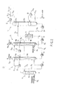
- FIG. 2 is a schematic diagram of a CO 2 recovery apparatus installed in the LNG production plant shown in FIG. 1.
- the LNG production plant comprises a CO 2 recovery apparatus 10, a natural gas liquefying apparatus 40 having a steam turbine (not shown), a boiler 50 serving as a power source, and a compressor 62 driven by, for example, a steam turbine 61.
- a natural gas passageway 70 1 is connected to the CO 2 recovery apparatus 10, which is connected to the boiler 50 through a combustion exhaust gas passageway 70 2 .
- the CO 2 recovery apparatus 10 comprises a cooling tower 11, a combustion exhaust gas absorption tower 12, a natural gas absorption tower 13, and a regeneration tower 14, all being arranged adjacent to each other.
- the cooling tower 11 incorporates a gas-liquid contact member 15.
- the combustion exhaust gas absorption tower 12 incorporates upper and lower gas-liquid contact members 16a and 16b.
- An overflow portion 17 for a regenerated absorbing liquid is arranged between the gas-liquid contact members 16a and 16b.
- the natural gas absorption tower 13 incorporates upper and lower gas-liquid contact members 18a and 18b.
- An overflow portion 19 for a regenerated absorbing liquid is arranged between the gas-liquid contact members 18a and 18b.
- the regeneration tower 14 incorporates upper and lower gas-liquid contact members 20a and 20b.
- the cooling tower 11 is connected to the boiler 50 through the combustion exhaust gas passageway 70 2 . Cooling water is sprayed to the upper portion of the cooling tower 11 through the circulating passageway 70 3 , so a combustion exhaust gas introduced through the passageway 70 2 is cooled with the gas-liquid contact member 15.
- the top of the cooling tower 11 is connected to near the lower portion of the combustion exhaust gas absorption tower 12 through a passageway 70 4 .
- a blower 21 is inserted in the passageway 70 4 .
- the bottom of the combustion exhaust gas absorption tower 12 is connected to a heat exchanger 22 through the passageway 70 5 , which is equipped with a pump 23.
- the natural gas passageway 70 1 is connected to the lower portion near the bottom of the natural gas absorption tower 13.
- the bottom of the absorption tower 13 is connected to the heat exchanger 22 through the passageways 70 6 and 70 5 .
- the passageway 70 6 is equipped with a pump 24.
- the heat exchanger 22 is connected to the portion located between the upper and lower gas-liquid contact members 20a and 20b of the regeneration tower 14 by a passageway 70 7 .
- the bottom of the generation tower 14 is connected to the upper portion (that is, to the overflow portion 17) of the combustion exhaust gas absorption tower 12 through a passageway 70 8 (which passes through the heat exchanger 22), and also connected to the upper portion (the overflow portion 19) of the natural gas absorption tower 13 through a passageway 70 9 , which is branched from the passageway 70 8 .
- the pump 25 is attached on the passageway 70 8 between the bottom of the regeneration tower 14 and the heat exchanger 22.
- one of the ends of the passageway 70 10 is connected to the overflow portion 17 and the other end is connected to the portion of the tower 12 right above the gas-liquid contact member 16a via a pump 26.
- An exhaust passageway 70 11 is connected to the top of the absorption tower 12.
- one of the ends of the passageway 70 12 is connected to the overflow portion 19 and the other end is connected to the portion of the tower 13 right above the gas-liquid contact member 18a via a pump 27.
- the one of the ends of a passageway 70 13 is connected to the top of the absorption tower 13 and the other end is connected to the natural gas liquefying apparatus 40. Note that a dewatering apparatus is attached to the passageway 70 13 .
- one of the ends of a passageway 70 14 is connected to the lower portion near the bottom of the regeneration tower 14 and the other end is connected to the portion of the regeneration tower 14 right under the gas-liquid contact member 20b.
- a heat exchanger (reboiler) 28 is attached to the passageway 70 14 .
- a passageway 70 15 which flows through low-pressure steam derived from the steam turbine 61 of the compressor 62 and the steam turbine (not shown) of the natural gas liquefying apparatus 40, crosses at the reboiler 28. The low pressure stream is heat-exchanged with the regenerated absorbing liquid which flows through the passageway 70 14 at the reboiler 28 and condensed.
- one of the ends of a passageway 70 16 is connected to the top of the regenerator 14 and the other end is connected to the compressor 62 via a heat exchanger 29 for cooling.
- a passageway 70 17 is branched off the passageway 70 16 downstream of the heat exchanger 29 and connected to the regeneration tower 14 at the portion right above the gas-liquid contact member 20a.
- the boiler 50 is connected to the steam turbine 61 for driving the compressor 62 by the passageway 70 18 feeding a high-pressure steam.
- the CO 2 recovery apparatus 10 is connected to the compressor 62 by the flow passage 70 16 . CO 2 gas is supplied to the compressor 62, compressed, and exhausted out of the system though a passageway 70 19 .
- the boiler 50 is connected to the steam turbine (not shown) of the natural gas liquefying apparatus 40 through a passageway 70 20 , which flows through high-pressure steam, and drives the apparatus 40 by the steam turbine.
- the natural gas liquefying apparatus 40 liquefies natural gas (containing not more than 50 ppm CO 2 ) which is supplied from the natural gas absorption tower 13.
- the liquefied natural gas (LNG) flows through the passageway 70 21 and stored in a predetermined tank.
- passageway 70 22 One of the ends of a passageway 70 22 is connected the steam turbine 61 and the other end is connected to the passageway 70 15 , which flows through low-pressure steam from the steam turbine (not shown) of the natural gas liquefying apparatus 40.
- the passageway 70 15 is connected to the reboiler 28 of the regeneration tower 14.
- the passageways 70 15 which flows through low-pressure steam derived from the steam turbine of the natural gas liquefying apparatus 40 and from the steam turbine 61 of the compressor 62, crosses at the reboiler 28. However, either one of the low-pressure streams may be introduced to the reboiler 28.
- natural gas is supplied to the lower portion near the bottom of the natural gas absorption tower 13 of the CO 2 recovery apparatus 10 (shown in FIG. 2) through the natural gas passageway 70 1 .
- the natural gas goes up through the lower gas-liquid contact member 18b of the natural gas absorption tower 13.
- the natural gas comes into contact with a regenerated absorbing liquid (e.g., a regenerated amine solution), which is supplied from the regeneration tower 14 to the overflow portion 19 through the passageway 70 8 and the passageway 70 9 (branched off the passageway 70 8 ) via a heater exchanger 22, thereby absorbing CO 2 contained the natural gas.
- a regenerated absorbing liquid e.g., a regenerated amine solution
- the natural gas further goes up through the overflow portion and the upper gas-liquid contact member 18a and comes into contact with the regenerated amine solution supplied to the upper portion near the top of the natural gas absorption tower 13 through the passageway 70 12 with the help of the function of the pump 27.
- CO 2 of the natural gas remaining unabsorbed is absorbed by the amine solution until the concentration of CO 2 becomes 50 ppm or less.
- the amine solution containing CO 2 is stored at the bottom of the absorption tower 13. Also, H 2 S contained in natural gas is absorbed and removed during this CO 2 absorption step.
- the natural gas from which CO 2 has been removed is supplied to a natural gas liquefying apparatus 40 through the passageway 70 13 .
- a moisture content is removed by a dewatering apparatus (not shown) arranged thereto.
- the natural gas liquefying apparatus 40 is driven by supplying high-pressure steam generated by the boiler 50 to the steam turbine (not shown) of the liquefying apparatus 40 through the passageway 70 20 and liquefies the natural gas dewatered.
- LNG is fed out from the passageway 70 21 and stored in a predetermined tank. Since the CO 2 level of the natural gas to be liquefied is as low as 50 ppm or less, dry ice is not produced in the natural gas liquefying process.
- the high-pressure steam is generated in the boiler 50 and supplied to the steam turbine 61 for driving the compressor 62 through the passageway 70 18 .
- high-pressure steam is generated by burning a fuel (e.g., natural gas). Therefore, a large amount of combustion exhaust gas containing CO 2 generates.
- the combustion exhaust gas is supplied in its entirety to the cooling tower 11 of the CO 2 recovery apparatus 10 (shown in FIG. 2) through the combustion exhaust gas passageway 70 2 and cooled by cooling water supplied through the passageway 70 3 while passing through the gas-liquid contact member 15.
- the cooled combustion exhaust gas is supplied from the top of the cooling tower 11 to the lower portion near the bottom of the combustion exhaust gas absorption tower 12 through the passageway 70 4 with the help of the blower 21.
- the combustion exhaust gas goes up through the lower gas-liquid contact member 16b in the absorption tower 12 and comes into contact with a regenerated amine solution, which is supplied from the regeneration tower 14 to the overflow portion 17 through the passageway 70 8 via the heat exchanger 22, thereby absorbing CO 2 contained in the combustion exhaust gas by the amine solution.
- the combustion exhaust gas further passes through the overflow portion 17 and the upper gas-liquid contact member 16a. During this process, the combustion exhaust gas comes into contact with the regenerated amine solution, which is supplied to the portion near the top of the absorption tower 12 through the passageway 70 10 with the help of the function of the pump 26. As a result, CO 2 of the natural gas remaining unabsorbed is absorbed. The amine solution containing CO 2 is stored at the bottom of the absorption tower 12. On the other hand, the combustion exhaust gas from which CO 2 has been removed is exhausted out of the system through the exhaust passageway 70 11 .
- the amine solution containing the absorbed CO 2 and stored at the bottom of the combustion exhaust gas absorption tower 12 is supplied to the heat exchanger 22 through the passageway 70 5 with the help of the function of the pump 23.
- the amine solution containing the absorbed CO 2 and stored at the bottom of the natural gas absorption tower 13 is supplied to the heat exchanger 22 through the passageway 70 6 (which is merged into the passageway 70 5 ) with the help of the pump 24.
- the amine solution containing the absorbed CO 2 passes through the heat exchanger 22, it is heat-exchanged with a regenerated amine solution having a relatively high temperature and supplied through the passageway 70 8 connected to the bottom of the regeneration tower 14.
- the amine solution containing the absorbed CO 2 is heated, whereas the regenerated amine solution is cooled.
- the amine solution containing CO 2 heated by the heat exchanger 22 is supplied to the portion located between the gas-liquid supply members 20a and 20b of the regeneration tower 14 through the passageway 70 7 and goes up through the lower gas-liquid contact member 20b. During this process, the amine solution containing CO 2 is separated into CO 2 and a regenerated amine solution.
- the regenerated amine solution is stored at the bottom of the regeneration tower 14, circulated through the passageway 70 14 and heat-exchanged at the reboiler 28, at which the passageway 70 14 crosses the passageway 70 15 , which flows through the low-pressured steam fed from the natural gas liquefying apparatus 40 and the steam turbine 61. Since the regenerated amine solution is heated as described, the temperature of the regeneration tower 14 itself increases and used as a heat source for separating the regenerated amine solution into CO 2 and regenerated amine solution.
- the regenerated amine solution is stored at the bottom of the regeneration tower 14 and fed back to the combustion exhaust gas absorption tower 12 through the passageway 70 8 and to the natural gas absorption tower 13 through the passageways 70 8 and 70 9 (branched from 70 8 ), respectively, with the function of the pump 25.
- the CO 2 exhaust separated by the regeneration tower 14 goes up through the upper gas-liquid contact member 20a and exhausted from the top through the passageway 70 16 .
- the CO 2 exhaust flows through the passageway 70 16 , it is cooled by the heat exchanger 29 to condense amine vapor contained in the CO 2 exhaust into amine solution, which is fed back to the regeneration tower 14 by way of the branched passageway 70 17.
- CO 2 is supplied to the compressor 62 through the passageway 70 16 .
- high-pressure steam is supplied from the boiler 50 to the turbine 61 through the passageway 70 18 to drive the turbine 61.
- CO 2 supplied to the compressor is compressed and exhausted out of the system, for example, by supplying it to a urea plant, methanol plant, dimethyl ether plant, lamp oil/light oil synthesizing (GTL) plant, or the ground, through the passageway 70 19 .
- GTL lamp oil/light oil synthesizing
- the low-pressure steam fed from the steam turbine 61 passes through the passageway 70 22 , merges into low-pressure steam supplied from the steam turbine of the natural gas liquefying apparatus 40 and flowing through the passageway 70 15 , and enters the CO 2 recovery apparatus 10.
- the CO 2 recovery apparatus 10 more specifically, at the reboiler 28, the low-pressure steam is exchanged with the regenerated amine solution circulated through the passageway 70 14 .
- the regenerated amine solution is heated and conversely the low-pressure steam is cooled to condense into water.
- the condensed water is fed back to the boiler 50 (as a boiler water) through the passageway 70 15 .
- liquefied natural gas LNG
- CO 2 is recovered from the natural gas and the combustion exhaust gas generated in the boiler 50 by the CO 2 recovery apparatus 10
- the recovered CO 2 is supplied to the compressor 62 driven by the steam turbine 61, which is driven by supplying high-pressure steam from the boiler 50, compressed and discharged out of the system.
- the compressor 62 driven by the steam turbine 61
- the steam turbine 61 which is driven by supplying high-pressure steam from the boiler 50, compressed and discharged out of the system.
- no CO 2 or less amount of CO 2 is exhausted from the boiler 50. Since the amount of CO 2 is reduced, CO 2 emission tax is reduced. It is favorable in view of economy and preventing global warming.
- CO 2 can be efficiently used by supplying compressed CO 2 from which H 2 S has been removed, to a urea plant, methanol plant, dimethyl ether plant, or lamp oil/light oil synthesizing (GTL)plant.
- GTL lamp oil/light oil synthesizing
- the combustion exhaust gas absorption tower 12 and the natural gas absorption tower 13 share the regeneration tower 14.
- the CO 2 recovery apparatus 10 can be reduced in size and, by extension, the entire LNF production plant can be miniaturized.
Landscapes
- Engineering & Computer Science (AREA)
- Chemical & Material Sciences (AREA)
- Chemical Kinetics & Catalysis (AREA)
- Thermal Sciences (AREA)
- General Engineering & Computer Science (AREA)
- Physics & Mathematics (AREA)
- Mechanical Engineering (AREA)
- Oil, Petroleum & Natural Gas (AREA)
- General Chemical & Material Sciences (AREA)
- Organic Chemistry (AREA)
- Analytical Chemistry (AREA)
- Inorganic Chemistry (AREA)
- Treating Waste Gases (AREA)
- Gas Separation By Absorption (AREA)
- Carbon And Carbon Compounds (AREA)
- Separation By Low-Temperature Treatments (AREA)
Abstract
Description
Claims (10)
- A plant for producing liquefied natural gas characterized by comprising:a carbon dioxide recovery apparatus for natural gas absorbing and removing carbon dioxide from natural gas;a liquefying apparatus (40) having a steam turbine, for liquefying the natural gas from which carbon dioxide has been removed by the carbon dioxide recovery apparatus;a boiler equipment (50) for supplying steam to the steam turbine of the liquefying apparatus (40); anda carbon dioxide recovery apparatus (10) for combustion exhaust gas including an absorption tower (12) for absorbing carbon dioxide from combustion exhaust gas exhausted from the boiler equipment (50) by absorbing liquid, and a regeneration tower (14) for separating and recovering carbon dioxide from the absorbing liquid.
- The plant for producing liquefied natural gas according to claim 1, characterized in that the carbon dioxide recovery apparatus for natural gas has an absorption tower (13) for absorbing and removing carbon dioxide from natural gas by an absorbing liquid, and an regeneration tower for separating and recovering carbon dioxide from the absorbing liquid, the regeneration tower also serving as the regeneration tower (14) of the carbon dioxide recovery apparatus (10) for combustion exhaust gas.
- The plant for producing liquefied natural gas according to claim 2, further comprises a compressor (62) equipped with a steam turbine (61) for compressing carbon dioxide separated and recovered from the absorbing liquid.
- The plant for producing liquefied natural gas according to claim 3, characterized in that the steam turbines installed in the compressor (62) and the liquefying apparatus (40) are driven by steam generated by the boiler equipment (50).
- The plant for producing liquefied natural gas according to claim 3, characterized in that the regeneration tower (14) of the carbon dioxide recovery apparatus (10) further comprises a reboiler (28) using low-pressure steam supplied from at least one of the steam turbines as a heat source.
- A method for producing liquefied natural gas characterized by comprising the steps of:providing a plant for producing liquefied natural gas comprising:(a) a carbon dioxide recovery apparatus for natural gas absorbing and removing carbon dioxide from natural gas,(b) a liquefying apparatus (40) having a steam turbine, for liquefying the natural gas from which carbon dioxide has been removed by the carbon dioxide recovery apparatus,(c) boiler equipment (50) for supplying steam to the steam turbine of the liquefying apparatus (40), and(d) a carbon dioxide recovery apparatus (10) for combustion exhaust gas including an absorption tower (12) for absorbing carbon dioxide from combustion exhaust gas exhausted from the boiler equipment (50) by absorbing liquid, and a regeneration tower (14) for separating and recovering carbon dioxide from the absorbing liquid;absorbing and removing carbon dioxide of natural gas by the absorbing liquid in the carbon dioxide recovery apparatus for natural gas;liquefying the natural gas from which carbon dioxide has been removed by the carbon dioxide recovery apparatus for natural gas;absorbing and removing carbon dioxide of combustion gas exhausted from the boiler equipment (50) by the absorbing liquid in the carbon dioxide recovery apparatus (10) for combustion exhaust gas; andregenerating the absorbing liquid by separating and recovering carbon dioxide from the absorbing liquid containing carbon dioxide in the regeneration tower (14) of the carbon dioxide recovery apparatus (10) for. combustion exhaust gas.
- The method for producing liquefied natural gas according to claim 6, characterized in that the absorbing liquid containing carbon dioxide absorbed by the carbon dioxide recovery apparatus for natural gas and the absorbing liquid containing carbon dioxide absorbed by the carbon dioxide recovery apparatus (10) for combustion exhaust gas are regenerated by the same regeneration tower (14).
- The method for producing liquefied natural gas according to claim 7, characterized in that the carbon dioxide separated and recovered from the absorbing liquid in the regeneration tower (14) is compressed by a compressor (62) having a steam turbine (61) and thereafter exhausted out of the system.
- The method for producing liquefied natural gas according to claim 8, characterized in that the steam produced by the boiler equipment (50) is supplied to each of the steam turbines of the compressor (62) and the liquefying apparatus (40).
- The method for producing liquefied natural gas according to claim 8, characterized in that the regeneration tower (14) of the carbon dioxide recovery apparatus (10) further has a reboiler (28) and low pressure steam supplied from at least one of the steam turbines of the compressor (62) and the liquefying apparatus (40) is used as a heat source of the reboiler (28).
Applications Claiming Priority (2)
| Application Number | Priority Date | Filing Date | Title |
|---|---|---|---|
| JP2002240814A JP4138399B2 (en) | 2002-08-21 | 2002-08-21 | Method for producing liquefied natural gas |
| JP2002240814 | 2002-08-21 |
Publications (3)
| Publication Number | Publication Date |
|---|---|
| EP1391669A2 true EP1391669A2 (en) | 2004-02-25 |
| EP1391669A3 EP1391669A3 (en) | 2006-03-22 |
| EP1391669B1 EP1391669B1 (en) | 2008-04-02 |
Family
ID=31185199
Family Applications (1)
| Application Number | Title | Priority Date | Filing Date |
|---|---|---|---|
| EP03292057A Expired - Lifetime EP1391669B1 (en) | 2002-08-21 | 2003-08-20 | Plant and method for producing liquefied natural gas and recovering carbon dioxide contained in natural gas and in a combustion exhaust gas |
Country Status (4)
| Country | Link |
|---|---|
| US (1) | US6782714B2 (en) |
| EP (1) | EP1391669B1 (en) |
| JP (1) | JP4138399B2 (en) |
| AU (1) | AU2003235029B2 (en) |
Cited By (11)
| Publication number | Priority date | Publication date | Assignee | Title |
|---|---|---|---|---|
| WO2009076575A3 (en) * | 2007-12-13 | 2009-09-24 | Alstom Technology Ltd | System and method for regenerating an absorbent solution |
| EP1745844A4 (en) * | 2004-04-12 | 2010-02-17 | Mitsubishi Heavy Ind Ltd | Impurity disposal system and method |
| WO2011029792A1 (en) * | 2009-09-11 | 2011-03-17 | Siemens Vai Metals Technologies Gmbh | Method for removing co2 from exhaust gases of plants for producing raw iron |
| CN102114359A (en) * | 2011-01-13 | 2011-07-06 | 华东理工大学 | Micro-cyclone liquid collecting method and device for regeneration gas of flue gas and carbon dioxide capture system |
| EP2109491A4 (en) * | 2007-02-02 | 2012-04-04 | Chevron Usa Inc | Methods and apparatus for removing acid gases from a natural gas stream |
| WO2012052262A1 (en) * | 2010-09-28 | 2012-04-26 | Siemens Aktiengesellschaft | Method for removing carbon dioxide, and also gas turbine installation with carbon dioxide removal |
| RU2482407C2 (en) * | 2007-06-26 | 2013-05-20 | Линде Акциенгезелльшафт | Method to remove carbon dioxide |
| ITUD20120130A1 (en) * | 2012-07-18 | 2014-01-19 | Danieli Off Mecc | APPARATUS AND METHOD FOR THE REMOVAL OF SULFUR FROM A NATURAL GAS FLOW TO BE SUPPLIED TO THE REFORMER OF A DIRECT REDUCTION PROCESS |
| CN103920367A (en) * | 2014-03-24 | 2014-07-16 | 湖南和道资源科技有限公司 | Constant temperature absorption method and equipment capable of removing carbon dioxide from biogas |
| US8833081B2 (en) | 2011-06-29 | 2014-09-16 | Alstom Technology Ltd | Low pressure steam pre-heaters for gas purification systems and processes of use |
| ES2983357A1 (en) * | 2024-05-28 | 2024-10-22 | Univ Madrid Politecnica | System and method for producing liquefied natural gas (LNG) with CO2 capture |
Families Citing this family (24)
| Publication number | Priority date | Publication date | Assignee | Title |
|---|---|---|---|---|
| JP2004168553A (en) * | 2002-11-15 | 2004-06-17 | Mitsubishi Heavy Ind Ltd | Manufacturing process for synthetic gas |
| JP4274846B2 (en) * | 2003-04-30 | 2009-06-10 | 三菱重工業株式会社 | Carbon dioxide recovery method and system |
| US6964180B1 (en) * | 2003-10-13 | 2005-11-15 | Atp Oil & Gas Corporation | Method and system for loading pressurized compressed natural gas on a floating vessel |
| JP5021917B2 (en) * | 2005-09-01 | 2012-09-12 | 三菱重工業株式会社 | CO2 recovery apparatus and method |
| WO2008081018A2 (en) * | 2007-01-04 | 2008-07-10 | Shell Internationale Research Maatschappij B.V. | Method and apparatus for liquefying a hydrocarbon stream |
| BRPI0720811A2 (en) * | 2007-03-13 | 2013-01-15 | Mitsui Shipbuilding Eng | Hydrate Gas Production Method |
| JP2008229496A (en) * | 2007-03-20 | 2008-10-02 | Cansolv Technologies Inc | Apparatus and method for separating/recovering carbon dioxide |
| WO2009093315A1 (en) * | 2008-01-23 | 2009-07-30 | Hitachi, Ltd. | Natural gas liquefaction plant and power supply equipment therefor |
| EP2127726A1 (en) * | 2008-05-29 | 2009-12-02 | Shell Internationale Researchmaatschappij B.V. | Method of regenerating a loaded sorbent using concentrated solar power and an apparatus therefor |
| EP2335813A1 (en) | 2009-12-01 | 2011-06-22 | Shell Internationale Research Maatschappij B.V. | Method and apparatus for the removal of a sorbate component from a process stream with subsequent regeneration of the sorbent using solar energy |
| US8454727B2 (en) | 2010-05-28 | 2013-06-04 | Uop Llc | Treatment of natural gas feeds |
| US8282707B2 (en) | 2010-06-30 | 2012-10-09 | Uop Llc | Natural gas purification system |
| CN102728200B (en) * | 2012-06-29 | 2014-04-02 | 青岛碱业股份有限公司 | Carbon absorption tower |
| AP2015008643A0 (en) * | 2013-02-08 | 2015-08-31 | Toyo Engineering Corp | Process for recovering carbon dioxide from combustion exhaust gas |
| CN103143248A (en) * | 2013-02-08 | 2013-06-12 | 珠海共同机械设备有限公司 | System for absorbing and desorbing low-content CO2 in industrial exhaust gas |
| KR20150120976A (en) * | 2013-02-19 | 2015-10-28 | 지멘스 악티엔게젤샤프트 | Process and apparatus for processing a gas stream, especially for processing a natural gas stream |
| CN105018164A (en) * | 2014-05-01 | 2015-11-04 | 北京蓝图工程设计有限公司 | Method for co-producing liquefied natural gas and urea by means of coke oven gas and converter gas |
| KR101738335B1 (en) | 2015-12-11 | 2017-05-23 | 한국에너지기술연구원 | Apparatus for removing water and acid gas of a natural gas |
| FR3052240B1 (en) * | 2016-06-02 | 2020-02-21 | L'air Liquide, Societe Anonyme Pour L'etude Et L'exploitation Des Procedes Georges Claude | PROCESS FOR LIQUEFACTION OF CARBON DIOXIDE FROM A NATURAL GAS STREAM |
| FR3052239B1 (en) * | 2016-06-02 | 2020-02-21 | L'air Liquide, Societe Anonyme Pour L'etude Et L'exploitation Des Procedes Georges Claude | PROCESS FOR LIQUEFACTION OF NATURAL GAS AND CARBON DIOXIDE |
| CN107042051A (en) * | 2017-01-10 | 2017-08-15 | 杨皓 | Preliminary clearning prevents frozen block technique before a kind of methanation LNG liquefaction |
| WO2020121008A1 (en) * | 2018-12-12 | 2020-06-18 | Total Sa | Process for combined removal of native co2 and anthropogenic co2 |
| JP7745421B2 (en) * | 2021-10-21 | 2025-09-29 | 三菱重工業株式会社 | CO2 capture system and CO2 capture method |
| US20250367593A1 (en) * | 2024-06-03 | 2025-12-04 | Air Products And Chemicals, Inc. | Combined Carbon Dioxide Removal Plant Process |
Family Cites Families (10)
| Publication number | Priority date | Publication date | Assignee | Title |
|---|---|---|---|---|
| US3642430A (en) * | 1969-09-19 | 1972-02-15 | Benson Field & Epes | Separation of carbon dioxide and hydrogen sulfide from gas mixtures |
| US4033735A (en) * | 1971-01-14 | 1977-07-05 | J. F. Pritchard And Company | Single mixed refrigerant, closed loop process for liquefying natural gas |
| FR2600554B1 (en) * | 1986-06-30 | 1988-09-02 | Elf Aquitaine | PROCESS AND DEVICE FOR DEACIDIFYING A GAS CONTAINING H2S OR / AND CO2 AS WELL AS MERCAPTANS |
| EP0502596B2 (en) * | 1991-03-07 | 1999-08-25 | Mitsubishi Jukogyo Kabushiki Kaisha | Apparatus and process for removing carbon dioxide from combustion exhaust gas |
| JP2792777B2 (en) * | 1992-01-17 | 1998-09-03 | 関西電力株式会社 | Method for removing carbon dioxide from flue gas |
| JP3626796B2 (en) * | 1995-10-03 | 2005-03-09 | 三菱重工業株式会社 | Method for removing high-concentration carbon dioxide from high-pressure natural gas |
| US5642630A (en) * | 1996-01-16 | 1997-07-01 | Abdelmalek; Fawzy T. | Process for solids waste landfill gas treatment and separation of methane and carbon dioxide |
| TW366409B (en) * | 1997-07-01 | 1999-08-11 | Exxon Production Research Co | Process for liquefying a natural gas stream containing at least one freezable component |
| US6248794B1 (en) * | 1999-08-05 | 2001-06-19 | Atlantic Richfield Company | Integrated process for converting hydrocarbon gas to liquids |
| US6579343B2 (en) * | 2001-03-30 | 2003-06-17 | University Of Notre Dame Du Lac | Purification of gas with liquid ionic compounds |
-
2002
- 2002-08-21 JP JP2002240814A patent/JP4138399B2/en not_active Expired - Fee Related
-
2003
- 2003-08-14 US US10/640,016 patent/US6782714B2/en not_active Expired - Lifetime
- 2003-08-14 AU AU2003235029A patent/AU2003235029B2/en not_active Ceased
- 2003-08-20 EP EP03292057A patent/EP1391669B1/en not_active Expired - Lifetime
Cited By (16)
| Publication number | Priority date | Publication date | Assignee | Title |
|---|---|---|---|---|
| EP1745844A4 (en) * | 2004-04-12 | 2010-02-17 | Mitsubishi Heavy Ind Ltd | Impurity disposal system and method |
| NO338626B1 (en) * | 2004-04-12 | 2016-09-19 | Mitsubishi Heavy Ind Ltd | Waste management system and method |
| EP2109491A4 (en) * | 2007-02-02 | 2012-04-04 | Chevron Usa Inc | Methods and apparatus for removing acid gases from a natural gas stream |
| RU2482407C2 (en) * | 2007-06-26 | 2013-05-20 | Линде Акциенгезелльшафт | Method to remove carbon dioxide |
| WO2009076575A3 (en) * | 2007-12-13 | 2009-09-24 | Alstom Technology Ltd | System and method for regenerating an absorbent solution |
| WO2011029792A1 (en) * | 2009-09-11 | 2011-03-17 | Siemens Vai Metals Technologies Gmbh | Method for removing co2 from exhaust gases of plants for producing raw iron |
| US9366180B2 (en) | 2010-09-28 | 2016-06-14 | Siemens Aktiengesellschaft | Method for removing carbon dioxide, and also gas turbine installation with carbon dioxide removal |
| CN103140272A (en) * | 2010-09-28 | 2013-06-05 | 西门子公司 | Method for removing carbon dioxide, and also gas turbine installation with carbon dioxide removal |
| RU2571142C2 (en) * | 2010-09-28 | 2015-12-20 | Сименс Акциенгезелльшафт | Method of precipitating carbon dioxide and gas turbine unit with carbon dioxide precipitation |
| WO2012052262A1 (en) * | 2010-09-28 | 2012-04-26 | Siemens Aktiengesellschaft | Method for removing carbon dioxide, and also gas turbine installation with carbon dioxide removal |
| CN102114359A (en) * | 2011-01-13 | 2011-07-06 | 华东理工大学 | Micro-cyclone liquid collecting method and device for regeneration gas of flue gas and carbon dioxide capture system |
| US8833081B2 (en) | 2011-06-29 | 2014-09-16 | Alstom Technology Ltd | Low pressure steam pre-heaters for gas purification systems and processes of use |
| ITUD20120130A1 (en) * | 2012-07-18 | 2014-01-19 | Danieli Off Mecc | APPARATUS AND METHOD FOR THE REMOVAL OF SULFUR FROM A NATURAL GAS FLOW TO BE SUPPLIED TO THE REFORMER OF A DIRECT REDUCTION PROCESS |
| CN103920367A (en) * | 2014-03-24 | 2014-07-16 | 湖南和道资源科技有限公司 | Constant temperature absorption method and equipment capable of removing carbon dioxide from biogas |
| CN103920367B (en) * | 2014-03-24 | 2016-07-27 | 贺少君 | The constant temperature absorption process of carbon dioxide removal and equipment from biogas |
| ES2983357A1 (en) * | 2024-05-28 | 2024-10-22 | Univ Madrid Politecnica | System and method for producing liquefied natural gas (LNG) with CO2 capture |
Also Published As
| Publication number | Publication date |
|---|---|
| AU2003235029A1 (en) | 2004-03-11 |
| EP1391669B1 (en) | 2008-04-02 |
| EP1391669A3 (en) | 2006-03-22 |
| AU2003235029B2 (en) | 2004-11-04 |
| JP4138399B2 (en) | 2008-08-27 |
| US20040035147A1 (en) | 2004-02-26 |
| US6782714B2 (en) | 2004-08-31 |
| JP2004077075A (en) | 2004-03-11 |
Similar Documents
| Publication | Publication Date | Title |
|---|---|---|
| US6782714B2 (en) | Plant and method for producing liquefied natural gas | |
| CA2362773C (en) | A method for removing and recovering co2 from exhaust gas | |
| CA2491163C (en) | Improved split flow process and apparatus | |
| TWI554325B (en) | Low emission power generation systems and methods | |
| US8696797B2 (en) | Carbon dioxide removal from synthesis gas at elevated pressure | |
| JP6186650B2 (en) | Low emission power generation system and method including carbon dioxide separation system | |
| RU2508158C2 (en) | Method and device for separation of carbon dioxide from offgas at electric power station running at fossil fuel | |
| CN103270253B (en) | For being burnt and CO by carbonaceous fuel 2the method of electric power is produced in trapping | |
| US20100162703A1 (en) | Process for reducing carbon dioxide emission in a power plant | |
| NO332159B1 (en) | Process and facilities for energy efficient capture and separation of CO2 from a gas phase | |
| CA2674745A1 (en) | Methods and apparatus for removing acid gases from a natural gas stream | |
| KR20110110244A (en) | Method and apparatus for separating carbon dioxide from exhaust gas from fossil fuel power plant | |
| KR20100022971A (en) | Method and absorbent composition for recovering a gaseous component from a gas stream | |
| CA2819498C (en) | Configurations and methods for gasification plants | |
| EP1419992B1 (en) | Synthetic gas manufacturing plant and synthetic gas manufacturing method | |
| GB2434330A (en) | Removal of CO2 from flue gas | |
| CA2737330C (en) | System for gas purification and recovery with multiple solvents | |
| WO2008090166A1 (en) | Process for enabling constant power output in a power plant integrated with a carbon dioxide capture unit | |
| JP7715807B2 (en) | Carbon dioxide recovery method and carbon dioxide recovery system using carbon dioxide cycle power generation equipment | |
| AU708792B2 (en) | A method for removing and preventing emissions into the atmosphere of carbon dioxide (CO2) from exhaust gases from heat engines |
Legal Events
| Date | Code | Title | Description |
|---|---|---|---|
| PUAI | Public reference made under article 153(3) epc to a published international application that has entered the european phase |
Free format text: ORIGINAL CODE: 0009012 |
|
| AK | Designated contracting states |
Kind code of ref document: A2 Designated state(s): AT BE BG CH CY CZ DE DK EE ES FI FR GB GR HU IE IT LI LU MC NL PT RO SE SI SK TR |
|
| AX | Request for extension of the european patent |
Extension state: AL LT LV MK |
|
| PUAL | Search report despatched |
Free format text: ORIGINAL CODE: 0009013 |
|
| AK | Designated contracting states |
Kind code of ref document: A3 Designated state(s): AT BE BG CH CY CZ DE DK EE ES FI FR GB GR HU IE IT LI LU MC NL PT RO SE SI SK TR |
|
| AX | Request for extension of the european patent |
Extension state: AL LT LV MK |
|
| 17P | Request for examination filed |
Effective date: 20060524 |
|
| 17Q | First examination report despatched |
Effective date: 20060721 |
|
| AKX | Designation fees paid |
Designated state(s): FR GB |
|
| 17Q | First examination report despatched |
Effective date: 20060721 |
|
| REG | Reference to a national code |
Ref country code: DE Ref legal event code: 8566 |
|
| 17Q | First examination report despatched |
Effective date: 20060721 |
|
| GRAP | Despatch of communication of intention to grant a patent |
Free format text: ORIGINAL CODE: EPIDOSNIGR1 |
|
| GRAS | Grant fee paid |
Free format text: ORIGINAL CODE: EPIDOSNIGR3 |
|
| GRAA | (expected) grant |
Free format text: ORIGINAL CODE: 0009210 |
|
| AK | Designated contracting states |
Kind code of ref document: B1 Designated state(s): FR GB |
|
| REG | Reference to a national code |
Ref country code: GB Ref legal event code: FG4D |
|
| RIN1 | Information on inventor provided before grant (corrected) |
Inventor name: SEIKI, YOSHIO, HIROSHIMA R&D CENTER, MITSUBISHI Inventor name: IJIMA, MASAKI Inventor name: OSORA, HIROYUKI,HIROSHIMA R&D CENTER,MITSUBISHI Inventor name: KOBAYASHI, KAZUTO,MITSUBISHI HEAVY IND., LTD. |
|
| ET | Fr: translation filed | ||
| PLBE | No opposition filed within time limit |
Free format text: ORIGINAL CODE: 0009261 |
|
| STAA | Information on the status of an ep patent application or granted ep patent |
Free format text: STATUS: NO OPPOSITION FILED WITHIN TIME LIMIT |
|
| 26N | No opposition filed |
Effective date: 20090106 |
|
| REG | Reference to a national code |
Ref country code: FR Ref legal event code: PLFP Year of fee payment: 13 |
|
| PGFP | Annual fee paid to national office [announced via postgrant information from national office to epo] |
Ref country code: FR Payment date: 20150629 Year of fee payment: 13 |
|
| REG | Reference to a national code |
Ref country code: FR Ref legal event code: ST Effective date: 20170428 |
|
| PG25 | Lapsed in a contracting state [announced via postgrant information from national office to epo] |
Ref country code: FR Free format text: LAPSE BECAUSE OF NON-PAYMENT OF DUE FEES Effective date: 20160831 |
|
| PGFP | Annual fee paid to national office [announced via postgrant information from national office to epo] |
Ref country code: GB Payment date: 20170816 Year of fee payment: 15 |
|
| GBPC | Gb: european patent ceased through non-payment of renewal fee |
Effective date: 20180820 |
|
| PG25 | Lapsed in a contracting state [announced via postgrant information from national office to epo] |
Ref country code: GB Free format text: LAPSE BECAUSE OF NON-PAYMENT OF DUE FEES Effective date: 20180820 |