EP1391537A1 - Coating forming method and coating forming material, and abrasive coating forming sheet - Google Patents
Coating forming method and coating forming material, and abrasive coating forming sheet Download PDFInfo
- Publication number
- EP1391537A1 EP1391537A1 EP02730834A EP02730834A EP1391537A1 EP 1391537 A1 EP1391537 A1 EP 1391537A1 EP 02730834 A EP02730834 A EP 02730834A EP 02730834 A EP02730834 A EP 02730834A EP 1391537 A1 EP1391537 A1 EP 1391537A1
- Authority
- EP
- European Patent Office
- Prior art keywords
- coating
- abrasive
- brazing filler
- filler metal
- particles
- Prior art date
- Legal status (The legal status is an assumption and is not a legal conclusion. Google has not performed a legal analysis and makes no representation as to the accuracy of the status listed.)
- Granted
Links
Images


Classifications
-
- F—MECHANICAL ENGINEERING; LIGHTING; HEATING; WEAPONS; BLASTING
- F01—MACHINES OR ENGINES IN GENERAL; ENGINE PLANTS IN GENERAL; STEAM ENGINES
- F01D—NON-POSITIVE DISPLACEMENT MACHINES OR ENGINES, e.g. STEAM TURBINES
- F01D11/00—Preventing or minimising internal leakage of working-fluid, e.g. between stages
- F01D11/08—Preventing or minimising internal leakage of working-fluid, e.g. between stages for sealing space between rotor blade tips and stator
- F01D11/12—Preventing or minimising internal leakage of working-fluid, e.g. between stages for sealing space between rotor blade tips and stator using a rubstrip, e.g. erodible. deformable or resiliently-biased part
-
- B—PERFORMING OPERATIONS; TRANSPORTING
- B23—MACHINE TOOLS; METAL-WORKING NOT OTHERWISE PROVIDED FOR
- B23K—SOLDERING OR UNSOLDERING; WELDING; CLADDING OR PLATING BY SOLDERING OR WELDING; CUTTING BY APPLYING HEAT LOCALLY, e.g. FLAME CUTTING; WORKING BY LASER BEAM
- B23K1/00—Soldering, e.g. brazing, or unsoldering
- B23K1/0008—Soldering, e.g. brazing, or unsoldering specially adapted for particular articles or work
- B23K1/0018—Brazing of turbine parts
-
- C—CHEMISTRY; METALLURGY
- C23—COATING METALLIC MATERIAL; COATING MATERIAL WITH METALLIC MATERIAL; CHEMICAL SURFACE TREATMENT; DIFFUSION TREATMENT OF METALLIC MATERIAL; COATING BY VACUUM EVAPORATION, BY SPUTTERING, BY ION IMPLANTATION OR BY CHEMICAL VAPOUR DEPOSITION, IN GENERAL; INHIBITING CORROSION OF METALLIC MATERIAL OR INCRUSTATION IN GENERAL
- C23C—COATING METALLIC MATERIAL; COATING MATERIAL WITH METALLIC MATERIAL; SURFACE TREATMENT OF METALLIC MATERIAL BY DIFFUSION INTO THE SURFACE, BY CHEMICAL CONVERSION OR SUBSTITUTION; COATING BY VACUUM EVAPORATION, BY SPUTTERING, BY ION IMPLANTATION OR BY CHEMICAL VAPOUR DEPOSITION, IN GENERAL
- C23C10/00—Solid state diffusion of only metal elements or silicon into metallic material surfaces
- C23C10/28—Solid state diffusion of only metal elements or silicon into metallic material surfaces using solids, e.g. powders, pastes
- C23C10/30—Solid state diffusion of only metal elements or silicon into metallic material surfaces using solids, e.g. powders, pastes using a layer of powder or paste on the surface
-
- C—CHEMISTRY; METALLURGY
- C23—COATING METALLIC MATERIAL; COATING MATERIAL WITH METALLIC MATERIAL; CHEMICAL SURFACE TREATMENT; DIFFUSION TREATMENT OF METALLIC MATERIAL; COATING BY VACUUM EVAPORATION, BY SPUTTERING, BY ION IMPLANTATION OR BY CHEMICAL VAPOUR DEPOSITION, IN GENERAL; INHIBITING CORROSION OF METALLIC MATERIAL OR INCRUSTATION IN GENERAL
- C23C—COATING METALLIC MATERIAL; COATING MATERIAL WITH METALLIC MATERIAL; SURFACE TREATMENT OF METALLIC MATERIAL BY DIFFUSION INTO THE SURFACE, BY CHEMICAL CONVERSION OR SUBSTITUTION; COATING BY VACUUM EVAPORATION, BY SPUTTERING, BY ION IMPLANTATION OR BY CHEMICAL VAPOUR DEPOSITION, IN GENERAL
- C23C10/00—Solid state diffusion of only metal elements or silicon into metallic material surfaces
- C23C10/60—After-treatment
-
- C—CHEMISTRY; METALLURGY
- C23—COATING METALLIC MATERIAL; COATING MATERIAL WITH METALLIC MATERIAL; CHEMICAL SURFACE TREATMENT; DIFFUSION TREATMENT OF METALLIC MATERIAL; COATING BY VACUUM EVAPORATION, BY SPUTTERING, BY ION IMPLANTATION OR BY CHEMICAL VAPOUR DEPOSITION, IN GENERAL; INHIBITING CORROSION OF METALLIC MATERIAL OR INCRUSTATION IN GENERAL
- C23C—COATING METALLIC MATERIAL; COATING MATERIAL WITH METALLIC MATERIAL; SURFACE TREATMENT OF METALLIC MATERIAL BY DIFFUSION INTO THE SURFACE, BY CHEMICAL CONVERSION OR SUBSTITUTION; COATING BY VACUUM EVAPORATION, BY SPUTTERING, BY ION IMPLANTATION OR BY CHEMICAL VAPOUR DEPOSITION, IN GENERAL
- C23C26/00—Coating not provided for in groups C23C2/00 - C23C24/00
-
- C—CHEMISTRY; METALLURGY
- C23—COATING METALLIC MATERIAL; COATING MATERIAL WITH METALLIC MATERIAL; CHEMICAL SURFACE TREATMENT; DIFFUSION TREATMENT OF METALLIC MATERIAL; COATING BY VACUUM EVAPORATION, BY SPUTTERING, BY ION IMPLANTATION OR BY CHEMICAL VAPOUR DEPOSITION, IN GENERAL; INHIBITING CORROSION OF METALLIC MATERIAL OR INCRUSTATION IN GENERAL
- C23C—COATING METALLIC MATERIAL; COATING MATERIAL WITH METALLIC MATERIAL; SURFACE TREATMENT OF METALLIC MATERIAL BY DIFFUSION INTO THE SURFACE, BY CHEMICAL CONVERSION OR SUBSTITUTION; COATING BY VACUUM EVAPORATION, BY SPUTTERING, BY ION IMPLANTATION OR BY CHEMICAL VAPOUR DEPOSITION, IN GENERAL
- C23C26/00—Coating not provided for in groups C23C2/00 - C23C24/00
- C23C26/02—Coating not provided for in groups C23C2/00 - C23C24/00 applying molten material to the substrate
-
- F—MECHANICAL ENGINEERING; LIGHTING; HEATING; WEAPONS; BLASTING
- F01—MACHINES OR ENGINES IN GENERAL; ENGINE PLANTS IN GENERAL; STEAM ENGINES
- F01D—NON-POSITIVE DISPLACEMENT MACHINES OR ENGINES, e.g. STEAM TURBINES
- F01D5/00—Blades; Blade-carrying members; Heating, heat-insulating, cooling or antivibration means on the blades or the members
- F01D5/12—Blades
- F01D5/14—Form or construction
- F01D5/20—Specially-shaped blade tips to seal space between tips and stator
-
- B—PERFORMING OPERATIONS; TRANSPORTING
- B23—MACHINE TOOLS; METAL-WORKING NOT OTHERWISE PROVIDED FOR
- B23K—SOLDERING OR UNSOLDERING; WELDING; CLADDING OR PLATING BY SOLDERING OR WELDING; CUTTING BY APPLYING HEAT LOCALLY, e.g. FLAME CUTTING; WORKING BY LASER BEAM
- B23K2101/00—Articles made by soldering, welding or cutting
- B23K2101/001—Turbines
-
- B—PERFORMING OPERATIONS; TRANSPORTING
- B23—MACHINE TOOLS; METAL-WORKING NOT OTHERWISE PROVIDED FOR
- B23K—SOLDERING OR UNSOLDERING; WELDING; CLADDING OR PLATING BY SOLDERING OR WELDING; CUTTING BY APPLYING HEAT LOCALLY, e.g. FLAME CUTTING; WORKING BY LASER BEAM
- B23K35/00—Rods, electrodes, materials, or media, for use in soldering, welding, or cutting
- B23K35/02—Rods, electrodes, materials, or media, for use in soldering, welding, or cutting characterised by mechanical features, e.g. shape
- B23K35/0222—Rods, electrodes, materials, or media, for use in soldering, welding, or cutting characterised by mechanical features, e.g. shape for use in soldering or brazing
- B23K35/0233—Sheets or foils
- B23K35/0238—Sheets or foils layered
-
- F—MECHANICAL ENGINEERING; LIGHTING; HEATING; WEAPONS; BLASTING
- F05—INDEXING SCHEMES RELATING TO ENGINES OR PUMPS IN VARIOUS SUBCLASSES OF CLASSES F01-F04
- F05D—INDEXING SCHEME FOR ASPECTS RELATING TO NON-POSITIVE-DISPLACEMENT MACHINES OR ENGINES, GAS-TURBINES OR JET-PROPULSION PLANTS
- F05D2230/00—Manufacture
- F05D2230/90—Coating; Surface treatment
-
- Y—GENERAL TAGGING OF NEW TECHNOLOGICAL DEVELOPMENTS; GENERAL TAGGING OF CROSS-SECTIONAL TECHNOLOGIES SPANNING OVER SEVERAL SECTIONS OF THE IPC; TECHNICAL SUBJECTS COVERED BY FORMER USPC CROSS-REFERENCE ART COLLECTIONS [XRACs] AND DIGESTS
- Y02—TECHNOLOGIES OR APPLICATIONS FOR MITIGATION OR ADAPTATION AGAINST CLIMATE CHANGE
- Y02T—CLIMATE CHANGE MITIGATION TECHNOLOGIES RELATED TO TRANSPORTATION
- Y02T50/00—Aeronautics or air transport
- Y02T50/60—Efficient propulsion technologies, e.g. for aircraft
-
- Y—GENERAL TAGGING OF NEW TECHNOLOGICAL DEVELOPMENTS; GENERAL TAGGING OF CROSS-SECTIONAL TECHNOLOGIES SPANNING OVER SEVERAL SECTIONS OF THE IPC; TECHNICAL SUBJECTS COVERED BY FORMER USPC CROSS-REFERENCE ART COLLECTIONS [XRACs] AND DIGESTS
- Y10—TECHNICAL SUBJECTS COVERED BY FORMER USPC
- Y10T—TECHNICAL SUBJECTS COVERED BY FORMER US CLASSIFICATION
- Y10T29/00—Metal working
- Y10T29/49—Method of mechanical manufacture
- Y10T29/49316—Impeller making
- Y10T29/4932—Turbomachine making
-
- Y—GENERAL TAGGING OF NEW TECHNOLOGICAL DEVELOPMENTS; GENERAL TAGGING OF CROSS-SECTIONAL TECHNOLOGIES SPANNING OVER SEVERAL SECTIONS OF THE IPC; TECHNICAL SUBJECTS COVERED BY FORMER USPC CROSS-REFERENCE ART COLLECTIONS [XRACs] AND DIGESTS
- Y10—TECHNICAL SUBJECTS COVERED BY FORMER USPC
- Y10T—TECHNICAL SUBJECTS COVERED BY FORMER US CLASSIFICATION
- Y10T428/00—Stock material or miscellaneous articles
- Y10T428/12—All metal or with adjacent metals
- Y10T428/12014—All metal or with adjacent metals having metal particles
- Y10T428/12028—Composite; i.e., plural, adjacent, spatially distinct metal components [e.g., layers, etc.]
- Y10T428/12049—Nonmetal component
-
- Y—GENERAL TAGGING OF NEW TECHNOLOGICAL DEVELOPMENTS; GENERAL TAGGING OF CROSS-SECTIONAL TECHNOLOGIES SPANNING OVER SEVERAL SECTIONS OF THE IPC; TECHNICAL SUBJECTS COVERED BY FORMER USPC CROSS-REFERENCE ART COLLECTIONS [XRACs] AND DIGESTS
- Y10—TECHNICAL SUBJECTS COVERED BY FORMER USPC
- Y10T—TECHNICAL SUBJECTS COVERED BY FORMER US CLASSIFICATION
- Y10T428/00—Stock material or miscellaneous articles
- Y10T428/31504—Composite [nonstructural laminate]
- Y10T428/31942—Of aldehyde or ketone condensation product
- Y10T428/31949—Next to cellulosic
Definitions
- This invention relates to a method of forming an abrasive coating, an oxidation-resistant coating or the like on, for example, a rotor blade, a stator blade, or a shroud in a combustion engine (gas turbine, jet engine, and the like) or a steam turbine, a coating formation material, an abrasive coating formation sheet, and a rotor blade in a gas turbine on which an abrasive coating or the like is formed by this coating formation method, and a gas turbine using this rotor blade.
- a combustion engine gas turbine, jet engine, and the like
- a steam turbine a coating formation material, an abrasive coating formation sheet, and a rotor blade in a gas turbine on which an abrasive coating or the like is formed by this coating formation method, and a gas turbine using this rotor blade.
- a predetermined clearance is provided between a tip of the rotor blade and the shroud that faces the tip of the rotor blade, so that the tip of the rotor blade and the shroud do not come in contact with each other during operation. If this clearance is too large, combustion gas leaks from the pressure surface side to the suction surface side of the rotor blade, thereby the combustion gas that can be used for driving the turbine decreases. As a result, the operation efficiency of the gas turbine decreases. Therefore, the clearance is set as small as possible, for suppressing the leak of the combustion gas as much as possible, to improve the performance of the gas turbine.
- the tip of the rotor blade and the shroud may slide with each other, resulting from thermal expansion of the rotor blade, eccentricity of a turbine rotor, vibrations occurring in the whole gas turbine, or the like (a so-called initial sliding).
- initial sliding the shroud exposed to the high-temperature gas gradually causes a thermal deformation, thereby the tip of the rotor blade and the shroud may slide with each other (a so-called secondary sliding).
- the shroud comprises a coating as a thermal insulation or antioxidation on the internal peripheral face thereof.
- a thermal barrier coating TBC
- McrAlY an antioxidant coating consisting of McrAlY may be provided, where M is one or more of iron, nickel, and cobalt.
- Japanese Patent Application Laid-Open Nos. 4-218698 and 9-504340, and US Patent No. 5,702,574 disclose a rotor blade having an abrasive coating, in which abrasive particles are dispersed in a matrix of McrAlY, which is an antioxidant material.
- McrAlY which is an antioxidant material.
- CBN cubic boron nitride
- the cubic boron nitride is a material having high hardness, and hence, if the rotor blade and the internal peripheral face of the shroud slide with each other, the abrasive particles comprising this cubic boron nitride polish the internal peripheral face of the shroud. As a result, appropriate clearance can be maintained between the rotor blade and the shroud.
- This abrasive coating may be formed as follows. That is, abrasive particles are temporarily fixed to the rotor blade body, and a matrix is formed around the abrasive particles by electrodeposition. In other words, the matrix is formed by the growth of a deposit. Since the growth of the deposit requires time, this forming method has poor efficiency. Further, the formation of the matrix by the electrodeposition is generally expensive. Further, electrodeposition needs large-scale equipment, and it is difficult to newly build the electrodeposition equipment from a standpoint of environmental protection.
- Japanese Patent Application Laid-Open No. 10-30403 discloses an abrasive coating formation method in which a matrix is formed by a thermal spraying method.
- the thermal spraying method is a method of allowing a metal layer to grow by injecting a molten metal, and has a feature in that it is highly efficient as compared with the electrodeposition method.
- the electrodeposition method is used. Therefore, it has the problems described above, and it is also difficult to accurately control the thickness of the matrix, and large-scale thermal spraying equipment is required.
- abrasive particles such as cubic boron nitride are dispersed in the metal matrix by the thermal spraying method, since the abrasive particles are buried in the molten metal, it is necessary to remove the molten metal until the abrasive particles are exposed. However, it is difficult to expose the abrasive particles, and hence, it becomes difficult for the abrasive particles to polish the internal peripheral face of the shroud. Further, the metal matrix may be welded on the internal peripheral face of the shroud, to damage the rotor blade.
- An antioxidant coating of the TBC or MCrAlY may be formed on the internal peripheral face of the shroud.
- These coatings are generally formed by the thermal spraying method, such as an atmospheric plasma spray (APS) method, a high velocity oxygen fuel (HVOF) method, a low pressure plasma spray (LPPS) method, or a detonation gun (D-GUN) method.
- APS atmospheric plasma spray
- HVOF high velocity oxygen fuel
- LPPS low pressure plasma spray
- D-GUN detonation gun
- the coating formation method according to the present invention includes the following steps (1) to (3).
- a coating is formed by a so-called brazing. This method is cheap as compared with the plating or thermal spraying method, and does not require large-scale equipment, and hence there is little limitation on the application site.
- a coating parameter between the brazing filler metal and the coating material laminated at the lamination step be from 30:70 to 70:30 inclusive, as in the coating formation method according to the present invention.
- the brazing filler metal is reliably melted in the coating material at the melting step, by selecting the volume ratio in this manner.
- the brazing filler metal contains boron. Boron diffuses in the coating material at the melting step, to allow the solidifying point of the coating material to fall. Therefore, even when the coating material is heated at a relatively low temperature, the coating material melts, and once it melts, boron decreases to raise the melting point. As a result, a problem such as remelting hardly occurs in the actual operation.
- the brazing filler metal is preferably selected from materials having a melting point lower than the heat treatment temperature of the object to be coated.
- the melting step can be executed at the same time with the heat treatment of the object to be coated.
- the coating material layer to be used is one in which coating material particles diffuse in a binder, as in the coating formation method according to the next invention.
- Lamination of the coating material becomes easy by the binder. Since the binder volatilizes substantially completely at the melting step, it is suppressed that the quality of the coating deteriorates due to the binder remaining in the coating. If a volatile binder is used, it volatilizes easily at the melting step. Hence, the quality of the coating can be further improved, by reducing the quantity of the binder remaining in the coating.
- the binder one that volatilizes at a low temperature is preferable, and it is also desired to select the binder having a certain degree of strength (rigidity) of the coating material after the binder has dried.
- a mass ratio between the binder and the coating material particles be from 15:85 to 2:1 inclusive.
- a preferable coating material layer includes one comprising, as main component, MCrAlY particles and cubic boron nitride particles.
- An abrasive coating can be obtained by this coating material layer.
- cubic boron nitride serves as abrasive particles
- MCrAlY becomes a matrix to fix the abrasive particles.
- the MCrAlY matrix also suppresses oxidation of the abrasive particles or the rotor blade material.
- the volume ratio between the MCrAlY particles and the cubic boron nitride particles is from 1:2 to 2:1 inclusive, from a standpoint of consistence of improvement in the polishing ability and reliable fixation of the abrasive particles.
- the abrasive coating polishes the internal peripheral face of the opposite shroud, and hence a damage of the rotor blade by adhesion can be prevented.
- this coating formation method it is desired to include an exposure step of removing a part of MCrAlY from the surface of the fixed coating material layer to expose the cubic boron nitride particles, as in the coating formation method according to the next invention.
- the preferable exposure method is blasting, as in the coating formation method according to the next invention.
- an abrasive harder than the MCrAlY particles but softer than the abrasive particles be used.
- MCrAlY can be removed efficiently from the formed abrasive coating, the abrasive particles can be exposed sufficiently.
- the particle size of the abrasive is smaller than that of the abrasive particles and smaller than the space between the abrasive particles.
- the abrasive particles attack the holder of the abrasive particles to cause a dropout, and hence precautions should be taken regarding this point.
- dropout of the abrasive particles can be suppressed to a minimum, while sufficiently exposing the abrasive particles, and hence sufficient polishing performance can be exhibited from the initial stage.
- the preferred coating material layer include one composed mainly of the MCrAlY particles, as in the coating formation method according to the next invention.
- a coating having an oxidation resistance and an intergranular corrosion resistance obtained by this coating material layer can be preferably used in various members of a gas turbine where high-temperature gas circulates, more specifically, in a rotor blade, a stator blade, and a shroud, as in the coating formation method according to the next invention.
- a coating formation coating material according to the next invention contains abrasive particles such as cubic boron nitride, Al2O3, SiC, or the like, a metal material having at least an oxidation resistance, and a binder. Since this coating formation coating material contains abrasive particles, a metal material, and a binder, the brazing filler metal is absorbed in the gap produced by volatilization of the binder, in the heat treatment at the time of coating formation. Thereby, dripping of the brazing filler metal to the surroundings can be considerably reduced, and hence the quality (uniformity of the coating thickness) after forming the coating on the object to be coated can be improved. As a result, since adjustment of the coating thickness after forming a coating can be kept to a minimum, the time and energy for coating formation can be reduced.
- the object to be coated of the present invention includes a rotor blade and a shroud of a gas turbine. Since these objects to be coated are used in an atmosphere where high-temperature combustion gas is injected, the life thereof becomes short because of the reduced thickness due to oxidation.
- the metal material contained in the coating formation coating material according to the present invention has an oxidation resistance, oxidation hardly occurs even in such an atmosphere. Therefore, the abrasive particles can be reliably held to demonstrate stable polishing performance, even in long-term use thereof. Further, it has an effect of reducing reduction of thickness of the base metal due to oxidation, and hence more stable operation of the gas turbine can be realized.
- a ratio between the mass of the binder and the mass of the abrasive particles and the metal material is from 15:85 to 2:1 inclusive.
- the metal material is MCrAlY. Since MCrAlY having an oxidation resistance is used as the metal material for forming a coating, even when a coating is formed on the rotor blade of a gas turbine used in a high-temperature oxidative atmosphere, the abrasive particles can be held for long time to maintain the polishing performance, and to protect the base metal from oxidation. As a result, stable operation of the gas turbine can be realized.
- the volume ratio between the MCrAlY particles and the abrasive particles is from 1:2 to 2:1 inclusive. If the ratio of the cubic boron nitride, Al2O3, or SiC used as the abrasive particles is large, the content of MCrAlY decreases, and hence not only the oxidation resistance decreases, but also insufficient brazing filler metal easily occurs at the time of application. Further, holding of the abrasive particles becomes insufficient during brazing, thereby causing a relief of particles. On the other hand, if the ratio of MCrAlY is too large, the polishing ability of the abrasive coating may be insufficient.
- the mass ratio is within the range described above, the occurrence of insufficient brazing filler metal can be prevented, and the workability can be improved. Further, since the oxidation resistance of the metal layer that holds the abrasive particles sufficiently is high, the particles can be stably held for long time, and dropout of the abrasive particles can be suppressed, thereby enabling reliable operation of the gas turbine.
- an abrasive coating formation sheet a brazing filler metal and any one of the coating formation coating materials described above are laminated.
- this abrasive coating formation sheet since a binder is contained in the coating formation coating material, the brazing filler metal is sucked in the space where the binder volatilizes, in the heat treatment at the time of coating formation.
- liquid dripping at the time of coating formation can be considerably reduced, and hence the quality after the coating has been formed on the object to be coated can be improved. Since the adjustment after coating formation can be kept to a minimum, the time and energy for coating formation can be reduced.
- This abrasive coating formation sheet is adhered to the object to be coated, and then the abrasive coating can be formed only by heat-treating the object to be coated, and hence the abrasive coating can be formed very easily, as compared with the plating or thermal spraying method. Further, if a metal material having an oxidation resistance and an intergranular corrosion resistance is used as the coating formation coating material, even when the abrasive coating is formed on the rotor blade, the shroud and the like in the gas turbine, which are used in a high-temperature oxidative atmosphere, dropout of the abrasive particles can be suppressed to thereby maintain stable polishing performance. As a result, stable operation of the gas turbine can be realized.
- the treatment prior to the heat treatment is completed only by adhering this abrasive coating formation sheet to the object to be coated, the work becomes very easy. Further, since it is a sheet form, it can be appropriately cut according to the shape of the object to be coated. Therefore, it can easily correspond to objects to be coated having various shapes.
- the coating parameter between the brazing filler metal and the coating formation coating material is from 30:70 to 70:30 inclusive.
- boron is contained in the brazing filler metal. Since boron is contained, at the melting step, this boron diffuses in the coating formation coating material, to allow the solidifying point of the coating formation coating material to fall. Therefore, even when the coating formation coating material is heated at a relatively low temperature, the coating formation coating material melts. After boron diffuses, since the melting point of the coating formation coating material increases, the heat resistance of the brazing filler metal increases. As a result, even when the coating formation coating material is used in a high-temperature gas, such as in the rotor blade and the shroud of the gas turbine, the brazing filler metal can be used without remelting.
- the brazing filler metal is selected from materials having a melting point lower than the heat treatment temperature of the object to be coated. As a result, the melting step is allowed to progress at the same time with the heat treatment of the object to be coated.
- an adhesive layer is formed on the brazing filler metal. Therefore, so long as the abrasive coating formation sheet is prepared, the treatment prior to the heat treatment is completed only by adhering the abrasive coating formation sheet on the object to be coated, without requiring pasting and waiting for drying of the paste. As a result, time and energy for coating formation can be reduced.
- a coating is formed at the tip thereof by any one of the coating formation methods. Therefore, the abrasive coating can be formed very easily, as compared with the plating or thermal spraying method. As a result, the time required for coating formation can be considerably reduced, as compared with the coating formation method described above, and the production cost thereof can be reduced.
- any one of the abrasive coating formation sheets is adhered to the tip thereof. Therefore, the abrasive coating can be formed only by performing the necessary heat treatment on the rotor blade, and hence the abrasive coating can be formed very easily, as compared with the plating or thermal spraying method. As a result, the time required for coating formation can be considerably reduced, as compared with the coating formation method described above, and the production cost thereof can be reduced.
- a gas turbine comprises: a compressor that compresses air to produce combustion air; a combustor that allows the combustion air produced by the compressor to react with a fuel, to generate a high-temperature combustion gas; and a turbine having a rotor blade driven by the combustion gas injected from the combustor to the rotor blade.
- the abrasive coating can be formed easily, and hence the equipment for coating formation becomes simple, as compared with the plating or thermal spraying method.
- the abrasive coating can be easily formed, if only a heating furnace used for the heat treatment is provided.
- the abrasive coating can be formed again on the rotor blade or the like, on the site. As a result, even if the abrasive coating is damaged, repair is easy.
- Fig. 1 is a flowchart that shows the coating formation method according to one embodiment of the present invention
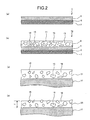
- Fig. 2 is a block diagram for explaining various steps in the coating formation method in Fig. 1
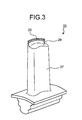
- Fig. 3 is a perspective view that shows a rotor blade, on which an abrasive coating is formed by the forming method in Fig. 1
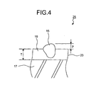
- Fig. 4 is an enlarged cross section that shows a part of the rotor blade shown in Fig. 3
- Fig. 5 shows a gas turbine having a gas turbine rotor blade, at the tip of which an abrasive coating is formed by the coating formation method according to the present invention.
- Fig. 1 is a flowchart of the coating formation method according to one embodiment of the present invention.
- This coating formation method is applied to a case in which a relatively simple apparatus (for example, a high vacuum heating furnace) is used, to form an abrasive coating at the tip of the rotor blade of a gas turbine.
- a brazing filler metal sheet is prepared (step S1).
- Fig. 2(a) is an enlarged cross section of a part of this brazing filler metal sheet, which is comprehensively denoted by reference sign 1.
- This brazing filler metal sheet 1 comprises a brazing filler metal layer 3 on the upper side in the figure, an intermediate sticking material layer 5 as an adhesive layer, and a released paper 7 on the lower side.
- the brazing fitter metal layer 3 comprises a brazing filler metal. If only the sticking material layer 5 and the lower side released paper 7 are provided, the released paper 7 is peeled off, and the brazing filler metal sheet 1 has only to be adhered on the object to be coated, and hence the work becomes very easy.
- the thickness of the brazing filler metal layer 3 is generally from 0.05 mm to 1.00 mm.
- the brazing filler metal layer 3 may be a single sheet or a bundle of two or three sheets.
- the intermediate sticking material layer 5, being an adhesive layer, and the lower released paper 7 may be provided according to need. When the intermediate sticking material layer 5 and the lower released paper 7 are not provided, the sheet 1 can be adhered on the object to be coated by pasting or the like, using a binder as a paste.
- a preferable brazing filler metal includes one containing boron (B) of from about 2.75 to 3.50% by mass and composed mainly of nickel (Ni).
- This brazing filler metal generally contains chromium (Cr) of from about 6 to 8% by mass, silicon (Si) of from about 4 to 5% by mass, and iron (Fe) of from about 2.5 to 3.5% by mass.
- the brazing filler metal sheet 1 is preferably one that is not hardened with lapse of time, and a specific example of the brazing filler metal sheet 1 includes BNi-2 (JIS Standard), or the like.
- the brazing filler metal sheet 1 is available in the market in the form such that the sticking material layer 5 and the released paper 7 are laminated on the brazing filler metal layer 3 in advance, and the brazing filler metal contains 83% by mass of nickel, 7% by mass of chromium, 3% by mass of boron, 4% by mass of silicon, and 3% by mass of iron.
- a coating material layer 9 shown in Fig. 2(b) is formed on the brazing filler metal sheet 1 (step S2). It is also possible to form the coating material layer 9 and the sheet 1 separately, cut them from where they were formed, and later stick them together by a binder or the like. In order to prevent cracking such as cut in multiple steps, these are formed as a bilayer with the soft BNi-2, to thereby improve the sectility of the whole sheet.
- the coating material layer 9 is formed by coating a mixture of coating material particles and a binder 11 on the surface of the brazing filler metal layer 3. At first, the mixture of the coating material particles and the binder 11 is poured on the brazing filler metal layer 3. Excessive mixture is scraped off, while spreading out the mixture in the form of sheet by a blade or the like, and coated in a predetermined thickness, taking the shrinkage allowance into consideration, when the mixture is dried.
- the coating material 9 is dried after coating (step S3), and generally air-dried for about one day. Because of the drying, the binder 11 volatilizes to some extent, whereby the thickness of the coating material layer 9 decreases.
- the predetermined thickness of the coating material layer 9 after coating may be about from 0.10 to 1.00 mm, so that the thickness of the coating material layer 9 after drying becomes not larger than the coating thickness of the brazing filler metal sheet 1, as a standard. Therefore, it is preferred to appropriately change the thickness of the coating material layer 9 after coating the mixture, depending on the mixing ratio of the binder 11 and the component ratio of the coating material layer 9.
- MCrAlY particles 13 being a metal material having an oxidation resistance and an intergranular corrosion resistance, are used as coating material particles, and cubic boron nitride particles 15 are used as the abrasive particles.
- coating material particles it is assumed that when it is simply referred to as coating material particles, this indicates both of these particles.
- the binder is mixed with the coating material particles and the abrasive particles, to become the coating formation coating material that forms the coating material layer 9.
- MCrAlY is an alloy mainly composed of iron (Fe), nickel (Ni) or cobalt (Co), a chromium (Cr), aluminum (Al), and yttrium (Y), having the oxidation resistance and the intergranular corrosion resistance. It is preferred to increase the content of Cr and Al, to improve the intergranular corrosion resistance and the oxidation resistance, taking it into consideration that MCrAlY is diluted by the Ni brazing filler metal, after forming a coating. However, if the quantity of these, particularly, the quantity of Al is too much, the brazing property deteriorates, and hence precautions should be taken. In order to improve the oxidation resistance, the intergranular corrosion resistance, and the brazing property, Ta, Re, Hf, Si or the like can be added, in addition to Cr and Al.
- the MCrAlY it is preferred to use one having the particle size in the range of from 10 to 100 ⁇ m at random, in order to increase the filling rate. However, if the particle size is too small, the surface area becomes too large, thereby disadvantageously increasing the amount of impurities such as O and N.
- cubic boron nitride particles 15 one put on the market by General Electric company, De Beers industrial Diamonds, Showa Denko K.K., Sumitomo Electric Industries, Ltd. and the like can be used.
- the cubic boron nitride is classified in single crystal and polycrystal, and high purity products exist. It is possible to use the right one in the right place, but it becomes clear that one obtained by coating cubic boron nitride with TiN or the like has excellent brazing property.
- Coating on the cubic boron nitride improves the wettability between the cubic boron nitride and the brazing filler metal, and hence the cubic boron nitride particles 15 can be sufficiently buried in the brazing filler metal. Thereby, dropout of the cubic boron nitride particles 15 can be suppressed. As a result, the TBC layer or the like on the shroud can be shaved off stably, thereby preventing welding between the tip of the rotor blade and the shroud, and enabling highly reliable operation.
- one obtained by coating the cubic boron nitride with Co or Ni, or one obtained by coating the cubic boron nitride with TiN or a Ti compound may be used. It is desired to appropriately select these depending on the kinds of the MCrAlY particles forming the coating material layer 9.
- Al 2 O 3 , SiC, and the like may be used as the abrasive particles, instead of the cubic boron nitride particles 15.
- Al 2 O 3 , SiC, or the like is used in order to improve the wettability with the brazing filler metal, it is preferred to use Al 2 O 3 or SiC applied with coating.
- Al 2 O 3 or SiC applied with coating.
- Co, Cr, Ni and the like can be mentioned as these coating materials.
- SiC is used as the abrasive particles
- AIN, TiN, Al 2 O 3 and the like can be mentioned as the coating material used for suppressing the reaction with SiC and Cr during brazing.
- the volume ratio of the volume V M of the MCrAlY particles 13 to the volume V C of the cubic boron nitride particles 15, V M :V C is preferably from 30:70 to 70:30 inclusive. If the ratio of the cubic boron nitride particles 15 is large, percentage of voids in the brazing filler metal sheet 1 increases, and the amount of the binder also increases. As a result, insufficient brazing filler metal and deformation likely occur. If the percentage of the cubic boron nitride particles 15 exceeds 70%, that is, the volume ratio V M :V C is smaller than 30:70, the density of the cubic boron nitride particles 15 is too large, and electric discharge machining from above the coating becomes difficult.
- the holding power for the cubic boron nitride particles 15 decreases to cause dropout of the cubic boron nitride particles 15.
- the volume ratio V M :V C exceeds 70:30, the polishing ability of the abrasive coating may be insufficient.
- the volume ratio V M :V C is more preferable to have the volume ratio V M :V C of not larger than 2:1, and particularly preferable to have the volume ratio V M :V C of not larger than 60:40. Therefore, the most preferable range of the volume ratio V M :V C is from 40:60 to 60:40 inclusive.
- the sheet 1 is prepared under mass control.
- the cubic boron nitride particle 15 has high hardness at high temperatures and excellent machinability, but disappears in a short period of time in a high-temperature oxidative atmosphere. Therefore, it is necessary to use it by mixing it with SiC, Al 2 O 3 , and the like having excellent long term stability. These volume ratios are also applicable, when Al 2 O 3 , TiN and the like are used, instead of the cubic boron nitride particles 15, or together with the cubic boron nitride particles 15.
- binders can be used as the binder 11, but it is particularly preferable to use one that volatilizes at a low temperature.
- the volatile binder 11 volatilizes in the dry step and the melting step described later in detail, and hence hardly remains in the abrasive coating. Therefore, it does not adversely affect the quality of the abrasive coating. Further, after the volatile binder 11 volatilizes, a gap is formed. In the melting step described later, since the brazing filler metal is absorbed in this gap due to the capillary phenomenon, liquid dripping can be considerably reduced. As a result, degradation of the rotor blade due to the liquid dripping is suppressed, and a treatment for the liquid dripping (mainly application of stop-off) is hardly required, and hence time and energy for application can be improved.
- Organic binders can be preferably used as the preferable volatile binder 11, and particularly, a cellulose binder is more preferable because of having excellent flowability of the brazing filler metal.
- a binder in which a plasticizer is added to the binder is used, flexibility is added to the abrasive coating formation sheet 1a described later, thereby enabling improvement in the workability, such that the sheet becomes easy to cut, or the like, which is preferable.
- the mass ratio m B :m C of the mass ratio m B of the volatile binder 11 to the mass ratio m C of the coating material particles 13 and 15 is preferably from 15:85 to 2:1 inclusive. If the mass ratio m B :m C is less than the lowest limit of the above range, there is the possibility that the coating of the mixture of the coating material particles 13 and 15 and the binder 11 becomes difficult. From this point of view, it is more preferable that the mass ratio m B :m C be not smaller than 20:80 (1:4), and most preferable that the mass ratio m B :m C be not smaller than 1:2.
- the mass ratio m B :m C exceeds the upper limit of the above range, liquid dripping likely occurs at the time of heat treatment of the object to be coated. From this point of view, it is more preferable that the mass ratio m B :m C be not larger than 60:40, and most preferably, not larger than 40:60. Therefore, the preferable range of the mass ratio m B :m C of the volatile binder 11 to the coating material particles 13 and 15 is from 20:80 to 40:60 inclusive.
- the coating parameter between the brazing filler metal and the coating material is preferably from 30:70 to 70:30 inclusive. If this coating parameter is less than the lowest limit of the above range, the coating material does not infiltrate in the brazing filler metal at the melting step, thereby easily causing insufficient brazing filler metal. From this point of view, it is particularly preferable that the coating parameter be not smaller than 60:40.
- the sheet 1 is dried at a normal temperature, in order to facilitate the cutting operation, and volatilize the excessive binder. It is desired to dry the sheet for the entire day or longer in a thermostatic chamber, if possible, in which the temperature and humidity are controlled.
- the brazing filler metal sheet 1 on which the coating material layer 9 is laminated (hereinafter referred to as an abrasive coating formation sheet 1a) is cut into a predetermined shape and size (step S4).
- the cutting means is not particularly limited, but since the abrasive coating formation sheet 1a has high brittleness, it is preferred to use a stencil and a ultrasonic cutter.
- the released paper 7 is peeled off from the abrasive coating formation sheet 1a cut into the predetermined shape and size, and adhered on the tip of the rotor blade, being the object to be coated (step S5).
- the abrasive coating formation sheet 1a Since the abrasive coating formation sheet 1a is cut into a blade shape, the majority thereof remains as unused waste pieces. Since expensive cubic boron nitride is contained in the abrasive coating formation sheet 1a, it is necessary to recover the cubic boron nitride. However, a coating for improving the brazing property is applied on the surface of the cubic boron nitride, and hence it is important to recover the cubic boron nitride without damaging this coating.
- pretreatment such as blasting, or cleaning by a solvent such as trichloroethylene, acetone or the like
- a solvent such as trichloroethylene, acetone or the like
- a hole for the cooling medium such as cooling air and cooling steam to gush out from the internal cooling passage may be provided at the tip of the rotor blade. Therefore, if this hole is closed when the abrasive coating formation sheet 1a is attached to the tip of the rotor blade, the cooling medium cannot gush out during the operation of the gas turbine, and hence cooling of the rotor blade may be insufficient. Therefore, the abrasive coating formation sheet 1a is attached, avoiding the portion of the hole, from which the cooling medium gushes out. However, if the diameter of the hole is small and there are many holes, it is difficult to avoid these holes.
- the abrasive coating formation sheet 1a is easily cut, and hence it is difficult to ensure the hole in this sheet before attaching the sheet. Therefore, punching is possible after attaching the sheet, by electric discharge machining or the like. Punching by the electric discharge machining is possible, regardless of before or after the cubic boron nitride particles are exposed.
- the abrasive coating formation sheet 1a is then heated together with the rotor blade body (step S6).
- a vacuum heating furnace is normally used for heating. The heating conditions are determined, taking into consideration the material of the rotor blade body and the kind of the brazing filler metal. For example, when the material of the rotor blade body is a base metal of the rotor blade (Ni group super alloy or the like), and the BNi-2 is used as the sheet 1 used for the abrasive coating formation sheet 1a, at first, the temperature of the vacuum heating furnace is raised from a room temperature to about 600°C over 10 hours or more.
- the abrasive coating formation sheet 1a Since the abrasive coating formation sheet 1a is heated, taking long time, to positively volatilize the binder 11 in the abrasive coating formation sheet 1 a at a low temperature, the component in the binder 11 that is likely to expand by heat does not remain at a high temperature. As a result, lines due to thermal expansion do not occur, and hence the quality of the formed abrasive coating can be improved. It is desired that the degree of vacuum at this time be higher than 10 -5 torr. Subsequently, the temperature is raised up to 1000°C or higher for about 2 hours, and the abrasive coating formation sheet 1a is held in this state for a required period of time. As a result, not only almost all the binder 11 volatilizes from the coating material layer 9, but also a gap is created in the coating material layer 9 after the binder 11 has volatilized.
- the brazing filler metal melts due to heating at 1000°C or higher.
- the brazing filler metal that becomes liquid form due to this heating infiltrates into the gap in the coating material layer 9 due to the capillary phenomenon, and absorbed in this gap.
- Boron being the brazing filler metal component, also diffuses in the MCrAlY particles 13 in the coating material layer 9. Since boron lowers the solidifying point of MCrAlY, MCrAlY becomes a half melted state, and easy to diffuse in the surrounding brazing filler metal.
- step S7 the strength required for the Ni alloy, being the base metal, can be obtained, and as shown in Fig. 2(c), a solidified layer 21 is formed, in which the cubic boron nitride particles 15 are dispersed in the MCrAlY matrix 19. Since boron disappears to some extent by holding the sheet at a controlled temperature of 1000°C or higher, the melting point of the matrix 19 rises to a temperature at which there is no practical problem.
- the heat treatment (stabilizing treatment) required for increasing the strength of the rotor blade is executed. In other words, melting of the coating material and the heat treatment of the rotor blade are completed at the same time at the melting step, by selecting a brazing filler metal having a melting point lower than the heat treatment temperature of the rotor blade.
- cubic boron nitride has a specific gravity lighter than that of the brazing filler metal, if the both materials are mixed beforehand, the cubic boron nitride particles 15 float in the surface layer in the liquid brazing filler metal, thereby causing unequal dispersion of the cubic boron nitride particles 15 in the solidified layer 21. Further, liquid dripping of the melted brazing filler metal easily occurs.
- the brazing filler metal layer 3 and the coating material layer 9 are sequentially laminated on the tip 17 of the rotor blade, to mix these by the capillary phenomenon.
- the cubic boron nitride particles 15 since being held by MCrAlY in the coating material layer 9, the cubic boron nitride particles 15 does not float up, thereby dispersion of the cubic boron nitride particles 15 becomes uniform, and liquid dripping of the brazing filler metal can be suppressed.
- step S8 blasting is applied to the solidified layer 21 (step S8).
- abrasive blasting particles are sprayed onto the surface of the matrix 19.
- the portion towards the surface of the matrix 19 is removed. Since the cubic boron nitride particles 15 are hardly removed by the blasting according to the present invention, the cubic boron nitride particles 15 protrude from the matrix 19 (a so-called "exposed”). In this manner, the abrasive coating 23 is completed.
- Fig. 2(d) the boundary between the abrasive coating 23 and the tip 17 of the rotor blade is clearly drawn, but in the actual rotor blade, the boundary between these becomes ambiguous due to the dispersion at the time of heating.
- the abrasive blasting particles having hardness lower than that of the cubic boron nitride particles 15 but higher than that of the matrix 19.
- the Vickers hardness of the matrix 19 is H1
- the Vickers hardness of the cubic boron nitride particles 15 is H2
- the Vickers hardness of the abrasive blasting particles used for the blasting is H3
- H1, H2, and H3 satisfy the relation expressed by the following expression (I): H1 ⁇ H3 ⁇ H2
- MCrAlY is used for the cubic boron nitride particles 15 and the matrix 19, for example, Al 2 O 3 particles can be used as the abrasive blasting particles.
- abrasive blasting particles having a size smaller than the space between the cubic boron nitride particles 15, and a size such that the abrasive blasting particles does not attack the base where the cubic boron nitride particles 15 are held.
- micro blasting using Al 2 O 3 particles having a mean particle size of 50 ⁇ m is used, but it is desired to appropriately select the diameter of the abrasive blasting particles to be used, based on the particle size of the cubic boron nitride particles 15 and spaces therebetween. For example, when the space between the cubic boron nitride particles 15 is large and the surface is rough, it is preferred to use a larger abrasive blasting particle. Further, in the abrasive coating, when Al 2 O 3 and SiC are used in the abrasive particles, it is preferred to use ZrO 2 , glass beads, and the like as the abrasive blasting particle.
- Fig. 3 is a perspective view of a rotor blade 25, on which an abrasive coating 23 is formed by the forming method in Fig. 1.
- the rotor blade 25 comprises a body 27 and a protruding portion 29 extending from the end of the body 27, and the abrasive coating 23 is coated on the upper face of the protruding portion 29, being the tip of the rotor blade.
- the internal peripheral face of the shroud is located, facing the abrasive coating 23, in the gas turbine.
- the internal peripheral face of the shroud is polished by the abrasive coating 23.
- a rotor blade having no protruding portion 29 may exist, but in this case, the abrasive coating can be formed at the tip of the rotor blade.
- the mean particle size of the cubic boron nitride particles 15 is preferably from about 50 to 200 ⁇ m. If the mean particle size is less than 50 ⁇ m, the polishing ability of the abrasive coating 23 may be insufficient. From this point of view, it is particularly preferable that the mean particle size be not smaller than 80 ⁇ m. On the other hand, if the mean particle size exceeds 200 ⁇ m, not only the coating thickness of the abrasive coating 23 becomes too large, but also the oxidation resistance of the abrasive coating 23 becomes insufficient. From this point of view, in the case of the rotor blade of the gas turbine, it is particularly preferable that the mean particle size be not larger than 170 ⁇ m. Therefore, the most preferable range of the mean particle size is from 80 to 170 ⁇ m.
- Fig. 4 is an enlarged cross section of a part of the rotor blade 25 shown in Fig. 3.
- the cubic boron nitride particles 15 protrude from the matrix 19.
- what is shown by two arrows p is a protrusion size of the cubic boron nitride particle 15.
- the mean particle size of the cubic boron nitride particles 15 is D
- a mean value of the protrusion size p in all cubic boron nitride particles 15 protruding from the matrix 19 that is, mean protrusion size
- the ratio of the mean protrusion size P to the mean particle size D is preferably from 25% to 70% inclusive.
- this ratio is less than 25%, the polishing ability of the abrasive coating 23 may be insufficient. From this point of view, it is more preferable that the ratio be not smaller than 30%. On the contrary, if this ratio exceeds 70%, the cubic boron nitride particles 15 may often drop out from the matrix 19. From this point of view, it is more preferable that the ratio be not larger than 60%. Therefore, the most preferable range of the ratio is from 30 to 60%.
- the thickness of the matrix 19 (the portion indicated by the duplex arrow T in Fig. 4) be not smaller than 50 ⁇ m. If the thickness of the matrix 19 is less than 50 ⁇ m, not only holding of the cubic boron nitride particles 15 in the abrasive coating 23 becomes insufficient, but also the distribution of the cubic boron nitride particles 15 cannot be arranged in a form of shark teeth, and hence the long-time high-temperature durability of the abrasive coating 23 decreases.
- the abrasive coating formation sheet 1a being a brazing filler metal sheet 1 laminated with the coating material layer 9, is used. This is cut into a predetermined shape and attached to the object to be coated, and then heat treatment is executed with respect to the object to be coated, to thereby form the abrasive coating 23 (see Fig. 3) on the object to be coated. Subsequently, the abrasive coating 23 is subjected to the blasting, to expose the cubic boron nitride particles 15, so that the abrasive particles protrude from the abrasive coating 23. After being manufactured in this manner, the abrasive coating formation sheet 1a is cut into a predetermined shape and attached to the object to be coated.
- the abrasive coating can be formed only by applying the necessary heat treatment to the object to be coated. Since blasting is used for exposing the abrasive particles, the abrasive particles can be allowed to protrude easily. As a result, the abrasive coating can be formed very easily, as compared with the conventional plating or thermal spraying method.
- the application cost can be suppressed to from 1:3 to 1:4 as that of the conventional plating method. Further, the time required for the application can be shortened to less than 1:3. Since considerable effect of decreasing the application cost and reducing the application period can be obtained, it is very useful when the abrasive coating is formed on a large number of rotor blades. Further, since large-scale equipment as in the plating method is not necessary, the cost required for the investment in plant and equipment can be reduced. Since wastewater from plating is not generated as in the plating method, environmental burden can be considerably reduced.
- the abrasive coating can be formed only by supplying the abrasive coating formation sheet 1a. Therefore, the heat treatment and the sheet preparation are not necessarily carried out at the same place. Hence, the freedom in application can be increased. For example, even in a gas turbine plant installed in a location where the application facility does not exist in the vicinity thereof, if only the heating equipment is provided and the abrasive coating formation sheet 1a is regularly supplied, recoating and the like can be performed on the site.
- the coating material is an oxidation resistant coating.
- This oxidation resistant coating is suitable for the rotor blade, the stator blade, or the shroud of a gas turbine.
- Fig. 5 shows a gas turbine having a gas turbine rotor blade, at the tip of which an abrasive coating is formed by the coating formation method according to the present invention.
- the air taken in from an air intake 50 is compressed by a compressor 51 to become high temperature and high pressure compressed air, and is fed to a combustor 52.
- the combustor 52 supplies a gas fuel such as natural gas or the like, or a liquid fuel such as gas oil, light fuel oil or the like to the compressed air, to burn the fuel, to thereby generate high temperature and high pressure combustion gas.
- This high temperature and high pressure combustion gas is guided to a combustor tail pipe 53, and injected to a turbine 54.
- the turbine 54 comprises a rotor blade 25 (see Fig. 3), at the tip of which an abrasive coating is formed by the coating formation method according to the present invention.
- the rotor blade 25 has a coating according to the present invention formed at the tip thereof.
- the coating formation method of the present invention since the abrasive particles are firmly brazed at the tip of the rotor blade 25, by the coating formation method of the present invention, the coating of TBC or the like (not shown) formed on the internal wall of the shroud 55 can be shaved off. As a result, welding of the rotor blade 25 can be prevented, and the gas turbine 100 can be stably operated. It is preferred that cubic boron nitride is allowed to function with respect to the initial sliding, and SiC and Al 2 O 3 having excellent long-term stability at high temperatures are allowed to function with respect to the secondary sliding. Therefore, it is more desirable to mix and use these, for ensuring the long-term reliability of the gas turbine.
- the rotor blade 25 according to the present invention has a coating formed at the tip thereof by brazing, and hence abrasive particles such as cubic boron nitride and the like can be distributed in a form of shark teeth. Therefore, even if the abrasive particles on the surface drop out, the next abrasive particles will appear. Hence, the coating of TBC or the like formed on the internal wall of the shroud 55 can be shaved off stably, until the abrasive coating 23 (see Fig. 3) disappears. As a result, more reliable operation can be realized than the case of using a rotor blade, on which a coating is formed by the conventional plating or thermal spraying method.
- the coating formation method of the present invention includes:
- the coating parameter between the brazing filler metal and the coating material laminated at the lamination step is set to from 30:70 to 70:30 inclusive. Therefore, not only the brazing filler metal is reliably melted at the melting step, but also the formed coating is firm, thereby improving the property thereof.
- the brazing filler metal contains boron, boron diffuses in the coating material at the melting step, to allow the solidifying point of the coating material to fall. Therefore, even when the coating material is heated at a relatively low temperature, the coating material can be reliably melted, at a low cost.
- a brazing filler metal having a melting point lower than the heat treatment temperature of the object to be coated is selected.
- the melting step can be executed at the same time with the heat treatment of the object to be coated.
- the work efficiency in forming the coating can be improved.
- the coating material layer in which coating material particles are dispersed in the binder, is used, lamination of the coating material becomes easy by the binder.
- the binder substantially completely volatilizes at the melting step, and hence degradation of the coating resulting from the remaining binder in the coating can be suppressed.
- the mass ratio between the binder and the coating material particles is from 15:85 to 2:1 inclusive.
- MCrAlY particles and cubic boron nitride particles are used as the main component.
- cubic boron nitride serves as abrasive particles
- MCrAlY becomes a matrix to fix the abrasive particles.
- the MCrAlY matrix can suppress oxidation of the abrasive particles.
- the volume ratio between the MCrAlY particles and the cubic boron nitride particles is from 1:2 to 2:1 inclusive. Therefore, the polishing ability of the abrasive coating is improved and the abrasive particles can be reliably fixed.
- the abrasive coating is formed at the tip of the rotor blade of a gas turbine, cubic boron nitride in the abrasive coating polishes the internal peripheral face of the opposite shroud, and hence a damage of the rotor blade can be prevented.
- an exposure step of removing a part of MCrAlY from the surface of the fixed coating material layer to expose the cubic boron nitride particles is included. Further, in the coating formation method according to the present invention, blasting is used at the exposure step of exposing the cubic boron nitride particles. As a result, exposure of the cubic boron nitride particles can be appropriately performed.
- an abrasive having a particle size smaller than the particle size of the abrasive particles and smaller than the spaces between the abrasive particles in the blasting, an abrasive having a particle size smaller than the particle size of the abrasive particles and smaller than the spaces between the abrasive particles.
- other examples of preferable coating material layers include one composed mainly of the MCrAlY particles.
- An oxidation resistant coating obtained by this coating material layer can be preferably used in various members of a gas turbine where high-temperature gas circulates, more specifically, in a rotor blade, a stator blade, and a shroud, as in the coating formation method according to the next invention.
- the brazing filler metal is absorbed in the gap produced by volatilization of the binder, in the heat treatment at the time of coating formation.
- liquid dripping of the brazing filler metal can be considerably reduced, and hence the quality after forming the coating on the object to be coated can be improved.
- the metal material has the oxidation resistance, oxidation hardly occurs even in a high temperature combustion gas atmosphere in which the rotor blade of the gas turbine is used.
- the abrasive particles can be reliably held, and stable polishing performance can be exhibited even in long-term use, and a reduced thickness due to oxidation of the base metal can be prevented. Hence, more stable operation of the gas turbine can be realized.
- a ratio between the mass of the binder and the mass of the abrasive particles and the metal material is from 15:85 to 2:1 inclusive.
- the metal material contained in the coating formation coating material is MCrAlY. Since MCrAlY having an oxidation resistance and an intergranular corrosion resistance is used, even when a coating is formed on the rotor blade of a gas turbine used in a high-temperature oxidative atmosphere, the abrasive particles can be held for long time to maintain the polishing performance. As a result, stable operation of the gas turbine can be realized.
- the volume ratio between the MCrAlY particles and the abrasive particles is from 1:2 to 2:1 inclusive. Therefore, the occurrence of insufficient brazing filler metal can be prevented, and the workability can be improved. Further, since abrasive particles can be sufficiently fixed, dropout of the abrasive particles can be suppressed, thereby enabling reliable operation of the gas turbine.
- the abrasive coating formation sheet according to the present invention a brazing filler metal and any one of the coating formation coating materials described above are laminated. Therefore, after this abrasive coating formation sheet is attached to the object to be coated, the abrasive coating can be formed only by heat-treating the object to be coated. Hence, the abrasive coating can be formed considerably easily, as compared with the plating or thermal spraying method. Further, since a treatment prior to the heat treatment is completed only by attaching the abrasive coating formation sheet to the object to be coated, the operation becomes very easy. Further, since it is a sheet form, it can be appropriately cut according to the shape of the object to be coated. Therefore, it can easily correspond to objects to be coated having various shapes.
- the coating parameter between the brazing filler metal and the coating formation coating material is set to from 30:70 to 70:30 inclusive. Therefore, not only the coating formation coating material reliably melts at the melting step, but also the formed coating becomes firm.
- boron is contained in the brazing filler metal. Since boron is contained, this boron diffuses in the coating formation coating material at the melting step, to allow the solidifying point of the coating formation coating material to fall. Therefore, even when the coating formation coating material is heated at a relatively low temperature, the coating formation coating material melts. After boron diffuses, since the melting point of the coating formation coating material increases, the heat resistance of the brazing filler metal increases. As a result, even when the coating formation coating material is used in a high-temperature gas, such as in the rotor blade and the shroud of a gas turbine, the brazing filler metal can be used without melting.
- the brazing filler metal is selected from materials having a melting point lower than the heat treatment temperature of the object to be coated. As a result, the melting step is allowed to progress at the same time with the heat treatment of the object to be coated.
- the abrasive coating formation sheet in the abrasive coating formation sheet, an adhesive layer is formed on the brazing filler metal. Therefore, so long as the abrasive coating formation sheet is prepared, the treatment prior to the heat treatment is completed only by adhering the abrasive coating formation sheet to the object to be coated, without requiring pasting and waiting for drying of the paste. As a result, time and energy for coating formation can be reduced.
- an abrasive coating is formed at the tip thereof by any one of the coating formation methods. Therefore, the abrasive coating can be formed very easily, as compared with the plating or thermal spraying method. As a result, the time required for coating formation can be considerably reduced, as compared with the coating formation method described above, and the production cost thereof can be reduced.
- any one of the abrasive coating formation sheets is adhered to the tip thereof. Therefore, the abrasive coating can be formed only by performing the necessary heat treatment on the rotor blade, and hence the abrasive coating can be formed considerably easily, as compared with the plating or thermal spraying method. As a result, the time required for coating formation can be considerably reduced, as compared with the coating formation method described above, and the production cost thereof can be reduced.
- a turbine driven by a combustion gas injected from the combustor comprises the rotor blade. Therefore, if only heat treatment equipment is provided, an abrasive coating can be easily formed on the rotor blade. Hence, even when there is no plating equipment near the operation site of the gas turbine, the abrasive coating can be easily formed, so long as a heating furnace used for heat treatment is equipped. As a result, since the abrasive coating can be formed again on the rotor blade on the site, repair of the rotor blade is easy.
- the coating formation method, the coating formation material, the abrasive coating formation sheet, the rotor blade of the gas turbine, on which an abrasive coating or the like is formed by the coating formation method, and the gas turbine using this rotor blade according to the present invention are useful in forming an abrasive coating, an oxidation resistant coating or the like, which is formed on a member such as a rotor blade, a stator blade, or a shroud in a combustion engine (gas turbine, jet engine, and the like) and a steam turbine, and is suitable for easily forming these coatings.
Landscapes
- Chemical & Material Sciences (AREA)
- Engineering & Computer Science (AREA)
- Mechanical Engineering (AREA)
- Chemical Kinetics & Catalysis (AREA)
- Materials Engineering (AREA)
- Metallurgy (AREA)
- Organic Chemistry (AREA)
- General Engineering & Computer Science (AREA)
- Turbine Rotor Nozzle Sealing (AREA)
- Polishing Bodies And Polishing Tools (AREA)
- Other Surface Treatments For Metallic Materials (AREA)
Abstract
Description
Claims (27)
- A coating formation method comprising:a lamination step of laminating a brazing filler metal layer and a coating material layer on the surface of an object to be coated, the brazing filler metal layer being composed essentially of a brazing filler metal, and the coating material layer being composed essentially of a coating material;a melting step of heating the laminated brazing filler metal layer and the coating material layer to allow at least a part of the coating material to melt, while diffusing the brazing filler metal in the coating material; anda fixing step of solidifying the melted coating material to fix it on the object to be coated.
- The coating formation method according to claim 1, wherein a coating parameter between the brazing filler metal and the coating material laminated at the lamination step is from 30:70 to 70:30 inclusive.
- The coating formation method according to claim 1 or 2, wherein the brazing filler metal component diffused in the coating material is boron.
- The coating formation method according to any one of claims 1 to 3, wherein the brazing filler metal is selected from materials having a melting point lower than the heat treatment temperature of the object to be coated.
- The coating formation method according to any one of claims 1 to 4, wherein the coating material layer is one in which coating material particles diffuse in a binder.
- The coating formation method according to claim 5, wherein a mass ratio between the binder and the coating material particles is from 15:85 to 2:1 inclusive.
- The coating formation method according to any one of claims 1 to 6, wherein the coating material layer comprises, as main component, MCrAlY particles and abrasive particles such as cubic boron nitride, Al2O3, TiN, or the like.
- The coating formation method according to claim 7, wherein the volume ratio between the MCrAlY particles and the abrasive particles is from 1:2 to 2:1 inclusive.
- The coating formation method according to claim 7 or 8, wherein the object to be coated is a tip of a rotor blade of a gas turbine.
- The coating formation method according to any one of claims 7 to 9, further comprising an exposure step, which is executed after the fixing step, of removing a part of MCrAlY from a surface of the fixed coating material layer to expose the abrasive particles.
- The coating formation method according to claim 10, wherein the exposure step is carried out by blasting.
- The coating formation method according to claim 11, wherein in the blasting, an abrasive harder than the MCrAlY particles but softer than the abrasive particles is used.
- The coating formation method according to claim 12, wherein the particle size of the abrasive is smaller than the particle size of the abrasive particles and smaller than the space between the abrasive particles.
- The coating formation method according to any one of claims 1 to 6, wherein the coating material layer is composed essentially of MCrAlY.
- The coating formation method according to claim 14, wherein the object to be coated is a rotor blade, a stator blade or a shroud of a gas turbine.
- A coating material containing abrasive particles such as cubic boron nitride, Al2O3, TiN, or the like, a metal material having at least an oxidation resistance, and a binder.
- The coating material according to claim 15 or 16, wherein a ratio between the mass of the binder and the mass of the abrasive particles and the metal material is from 15:85 to 2:1 inclusive.
- The coating material according to any one of claims 15 to 17, wherein the metal material is MCrAlY.
- The coating material according to of claim 18, wherein the volume ratio between the MCrAlY particles and the abrasive particles is from 1:2 to 2:1 inclusive.
- An abrasive coating formation sheet, wherein a brazing filler metal and a coating formation coating material according to any one of claims 15 to 19 are laminated.
- The abrasive coating formation sheet according to claim 20, wherein the coating parameter between the brazing filler metal and the coating formation coating material is from 30:70 to 70:30 inclusive.
- The abrasive coating formation sheet according to claim 20 or 21, wherein boron is contained in the brazing filler metal.
- The abrasive coating formation sheet according to any one of claims 20 to 22, wherein the brazing filler metal is selected from materials having a melting point lower than the heat treatment temperature of the object to be coated.
- The abrasive coating formation sheet according to claim 23, wherein an adhesive layer is formed on the brazing filler metal.
- A rotor blade of a gas turbine, comprising a coating at the tip thereof, the coating being formed by the coating formation method according to any one of claims 7 to 13.
- A rotor blade in a gas turbine, wherein the abrasive coating formation sheet according to any one of claims 20 to 24 is adhered to the tip thereof.
- A gas turbine comprising:a compressor that compresses air to produce combustion air;a combustor that allows the combustion air produced by the compressor to react with a fuel, to generate a high-temperature combustion gas; anda turbine having the rotor blade according to claim 25, and driven by the combustion gas injected from the combustor to the rotor blade.
Applications Claiming Priority (3)
| Application Number | Priority Date | Filing Date | Title |
|---|---|---|---|
| JP2001165659 | 2001-05-31 | ||
| JP2001165659 | 2001-05-31 | ||
| PCT/JP2002/005359 WO2002097160A1 (en) | 2001-05-31 | 2002-05-31 | Coating forming method and coating forming material, and abrasive coating forming sheet |
Publications (3)
| Publication Number | Publication Date |
|---|---|
| EP1391537A1 true EP1391537A1 (en) | 2004-02-25 |
| EP1391537A4 EP1391537A4 (en) | 2007-01-03 |
| EP1391537B1 EP1391537B1 (en) | 2012-02-22 |
Family
ID=19008304
Family Applications (1)
| Application Number | Title | Priority Date | Filing Date |
|---|---|---|---|
| EP20020730834 Expired - Lifetime EP1391537B1 (en) | 2001-05-31 | 2002-05-31 | Coating forming method and coating forming material, and abrasive coating forming sheet |
Country Status (5)
| Country | Link |
|---|---|
| US (1) | US7063250B2 (en) |
| EP (1) | EP1391537B1 (en) |
| JP (1) | JP3902179B2 (en) |
| CN (1) | CN1205357C (en) |
| WO (1) | WO2002097160A1 (en) |
Cited By (25)
| Publication number | Priority date | Publication date | Assignee | Title |
|---|---|---|---|---|
| WO2004111306A3 (en) * | 2003-06-12 | 2005-03-03 | Mtu Aero Engines Gmbh | Method for armour-plating the tips of rotating blades of a gas turbine mechanism and device for carrying out said method |
| EP1672174A1 (en) * | 2004-12-15 | 2006-06-21 | General Electric Company | Corrosion resistant coating composition, coated turbine component and method for coating same |
| EP1715140A1 (en) * | 2005-04-21 | 2006-10-25 | Siemens Aktiengesellschaft | Turbine blade with a cover plate and a protective layer on the cover plate |
| EP1930547A3 (en) * | 2006-11-24 | 2010-03-10 | IHI Corporation | Compressor blade for a gas turbine engine |
| WO2010130878A1 (en) * | 2009-05-15 | 2010-11-18 | Metso Minerals, Inc. | Corrosion protection under influence of corrosive species |
| WO2011002570A1 (en) * | 2009-06-30 | 2011-01-06 | General Electric Company | Rotor blade and method for reducing tip rub loading |
| EP2063072A3 (en) * | 2007-11-23 | 2011-03-09 | MTU Aero Engines AG | Sealing arrangement of a turbomachine and method of applying a protecting layer on a component of this turbomachine |
| EP2540868A1 (en) * | 2011-06-29 | 2013-01-02 | United Technologies Corporation | Spall resistant abradable turbine air seal |
| EP2317078A3 (en) * | 2009-11-02 | 2013-07-31 | Alstom Technology Ltd | Abrasive single-crystal turbine blade |
| EP2662474A1 (en) * | 2012-05-07 | 2013-11-13 | Siemens Aktiengesellschaft | Method of applying a protective coating to a turbine component |
| US8657570B2 (en) | 2009-06-30 | 2014-02-25 | General Electric Company | Rotor blade with reduced rub loading |
| US8662834B2 (en) | 2009-06-30 | 2014-03-04 | General Electric Company | Method for reducing tip rub loading |
| EP2876259A1 (en) * | 2013-11-26 | 2015-05-27 | General Electric Company | Turbine buckets with high hot hardness shroud-cutting deposits |
| EP2899371A1 (en) * | 2014-01-23 | 2015-07-29 | United Technologies Corporation | Fan Blades with Abrasive Tips |
| EP2924242A1 (en) * | 2014-03-28 | 2015-09-30 | United Technologies Corporation | Abrasive tip blade manufacture methods |
| EP2939783A1 (en) * | 2014-05-02 | 2015-11-04 | United Technologies Corporation | Abrasive sheathing |
| EP1987903B1 (en) * | 2007-04-30 | 2015-11-11 | United Technologies Corporation | Method for manufacturing a turbine engine component |
| EP2963143A3 (en) * | 2014-07-02 | 2016-02-10 | United Technologies Corporation | Abrasive coating and manufacture and use methods |
| EP3249173A1 (en) * | 2016-05-24 | 2017-11-29 | United Technologies Corporation | Abrasive coating for a substrate, turbine engine component and process for coating a turbine engine airfoil |
| US10018056B2 (en) | 2014-07-02 | 2018-07-10 | United Technologies Corporation | Abrasive coating and manufacture and use methods |
| EP3546702A1 (en) * | 2018-03-29 | 2019-10-02 | Siemens Aktiengesellschaft | Turbine blade for a gas turbine |
| US10786875B2 (en) | 2014-07-02 | 2020-09-29 | Raytheon Technologies Corporation | Abrasive preforms and manufacture and use methods |
| WO2020234079A1 (en) * | 2019-05-20 | 2020-11-26 | Siemens Aktiengesellschaft | Coated abrasive particles, coating method using same, coating system and sealing system |
| US11686208B2 (en) | 2020-02-06 | 2023-06-27 | Rolls-Royce Corporation | Abrasive coating for high-temperature mechanical systems |
| US20250079130A1 (en) * | 2023-08-28 | 2025-03-06 | Toto Ltd. | Structural member |
Families Citing this family (50)
| Publication number | Priority date | Publication date | Assignee | Title |
|---|---|---|---|---|
| US9409280B2 (en) | 1997-04-04 | 2016-08-09 | Chien-Min Sung | Brazed diamond tools and methods for making the same |
| US9238207B2 (en) | 1997-04-04 | 2016-01-19 | Chien-Min Sung | Brazed diamond tools and methods for making the same |
| US9221154B2 (en) | 1997-04-04 | 2015-12-29 | Chien-Min Sung | Diamond tools and methods for making the same |
| US9199357B2 (en) | 1997-04-04 | 2015-12-01 | Chien-Min Sung | Brazed diamond tools and methods for making the same |
| US9463552B2 (en) | 1997-04-04 | 2016-10-11 | Chien-Min Sung | Superbrasvie tools containing uniformly leveled superabrasive particles and associated methods |
| US9868100B2 (en) | 1997-04-04 | 2018-01-16 | Chien-Min Sung | Brazed diamond tools and methods for making the same |
| US7323049B2 (en) * | 1997-04-04 | 2008-01-29 | Chien-Min Sung | High pressure superabrasive particle synthesis |
| US20040124231A1 (en) * | 1999-06-29 | 2004-07-01 | Hasz Wayne Charles | Method for coating a substrate |
| JP2002256808A (en) | 2001-02-28 | 2002-09-11 | Mitsubishi Heavy Ind Ltd | Combustion engine, gas turbine and grinding layer |
| US20040038074A1 (en) * | 2001-11-01 | 2004-02-26 | Mark Manuel | Tool and a method for creating a tool |
| JP2003148103A (en) * | 2001-11-09 | 2003-05-21 | Mitsubishi Heavy Ind Ltd | Turbine and its manufacturing method |
| US9284647B2 (en) * | 2002-09-24 | 2016-03-15 | Mitsubishi Denki Kabushiki Kaisha | Method for coating sliding surface of high-temperature member, high-temperature member and electrode for electro-discharge surface treatment |
| WO2004029329A1 (en) * | 2002-09-24 | 2004-04-08 | Ishikawajima-Harima Heavy Industries Co., Ltd. | Method for coating sliding surface of high temperature member, and high temperature member and electrode for electric discharge surface treatment |
| CA2483528C (en) * | 2002-10-09 | 2015-07-21 | Ishikawajima-Harima Heavy Industries Co., Ltd. | Rotating member and method for coating the same |
| US7360991B2 (en) * | 2004-06-09 | 2008-04-22 | General Electric Company | Methods and apparatus for fabricating gas turbine engines |
| US20060051502A1 (en) * | 2004-09-08 | 2006-03-09 | Yiping Hu | Methods for applying abrasive and environment-resistant coatings onto turbine components |
| US7378132B2 (en) * | 2004-12-14 | 2008-05-27 | Honeywell International, Inc. | Method for applying environmental-resistant MCrAlY coatings on gas turbine components |
| US9724802B2 (en) | 2005-05-16 | 2017-08-08 | Chien-Min Sung | CMP pad dressers having leveled tips and associated methods |
| US8622787B2 (en) * | 2006-11-16 | 2014-01-07 | Chien-Min Sung | CMP pad dressers with hybridized abrasive surface and related methods |
| US8678878B2 (en) | 2009-09-29 | 2014-03-25 | Chien-Min Sung | System for evaluating and/or improving performance of a CMP pad dresser |
| US8393934B2 (en) | 2006-11-16 | 2013-03-12 | Chien-Min Sung | CMP pad dressers with hybridized abrasive surface and related methods |
| US8398466B2 (en) | 2006-11-16 | 2013-03-19 | Chien-Min Sung | CMP pad conditioners with mosaic abrasive segments and associated methods |
| US9138862B2 (en) | 2011-05-23 | 2015-09-22 | Chien-Min Sung | CMP pad dresser having leveled tips and associated methods |
| CA2679517C (en) | 2007-05-04 | 2014-02-11 | Mtu Aero Engines Gmbh | Method for manufacturing an abrasive coating on a gas turbine component |
| TWI388402B (en) | 2007-12-06 | 2013-03-11 | Methods for orienting superabrasive particles on a surface and associated tools | |
| DE102008003100A1 (en) * | 2008-01-03 | 2009-07-16 | Mtu Aero Engines Gmbh | Solder coating, method for coating a component, component and adhesive tape with a solder coating |
| KR101281828B1 (en) * | 2008-10-30 | 2013-07-03 | 미츠비시 쥬고교 가부시키가이샤 | Turbine moving blade having tip thinning |
| DE102009031313B4 (en) | 2009-06-30 | 2018-07-05 | MTU Aero Engines AG | Coating and method for coating a component |
| US8708659B2 (en) | 2010-09-24 | 2014-04-29 | United Technologies Corporation | Turbine engine component having protective coating |
| US8753093B2 (en) * | 2010-10-19 | 2014-06-17 | General Electric Company | Bonded turbine bucket tip shroud and related method |
| TWI487019B (en) | 2011-05-23 | 2015-06-01 | Cmp pad dresser having leveled tips and associated methods | |
| ES2706986T3 (en) | 2012-03-28 | 2019-04-02 | Alfa Laval Corp Ab | New brazing concept |
| US10183312B2 (en) * | 2014-05-23 | 2019-01-22 | United Technologies Corporation | Abrasive blade tip treatment |
| US10030527B2 (en) | 2014-07-02 | 2018-07-24 | United Technologies Corporation | Abrasive preforms and manufacture and use methods |
| US20160237832A1 (en) * | 2015-02-12 | 2016-08-18 | United Technologies Corporation | Abrasive blade tip with improved wear at high interaction rate |
| DE102015213555A1 (en) * | 2015-07-20 | 2017-03-09 | MTU Aero Engines AG | Sealing ridge armor and method of making the same |
| CN106194578A (en) * | 2016-08-09 | 2016-12-07 | 宁波锦浪新能源科技股份有限公司 | Wind blade protective layer and processing technology thereof |
| US11149744B2 (en) * | 2017-09-19 | 2021-10-19 | Raytheon Technologies Corporation | Turbine engine seal for high erosion environment |
| US10882158B2 (en) | 2019-01-29 | 2021-01-05 | General Electric Company | Peening coated internal surfaces of turbomachine components |
| DE102019202926A1 (en) | 2019-03-05 | 2020-09-10 | Siemens Aktiengesellschaft | Two-layer abrasive layer for blade tip, process component and turbine arrangement |
| US11299993B2 (en) | 2019-10-28 | 2022-04-12 | Honeywell International Inc. | Rotor assembly for in-machine grinding of shroud member and methods of using the same |
| US11612986B2 (en) | 2019-12-17 | 2023-03-28 | Rolls-Royce Corporation | Abrasive coating including metal matrix and ceramic particles |
| DE112021006071T5 (en) * | 2020-11-20 | 2023-09-07 | Kawasaki Jukogyo Kabushiki Kaisha | GAS TURBINE ENGINE ROTOR ASSEMBLY COMPONENT AND METHOD OF MANUFACTURING THEREOF |
| EP4245963B1 (en) * | 2022-03-16 | 2025-09-10 | Rolls-Royce Deutschland Ltd & Co KG | Gas turbine engine and method for manufacturing a rotor blade |
| CN114833415B (en) * | 2022-06-02 | 2023-05-23 | 南昌航空大学 | Method for vacuum electron beam brazing of wear-resistant coating of monocrystalline superalloy blade tip |
| CN115011904B (en) * | 2022-07-04 | 2024-02-09 | 福建华开电力科技有限公司 | Composite treatment method of anti-corrosion and anti-fouling metal material |
| CN116201759A (en) * | 2023-01-18 | 2023-06-02 | 河北德林机械有限公司 | Slurry pump product blended with small-particle alloy coating technology |
| CN117206611B (en) * | 2023-09-15 | 2026-03-27 | 浙江永旺焊材制造有限公司 | A brazing process and application for copper alloy-stainless steel composite structural components |
| CN117483739B (en) * | 2023-11-06 | 2025-01-24 | 郑州机械研究所有限公司 | A hard alloy bead with controllable blade height and its preparation method and application |
| US12508675B1 (en) * | 2024-08-19 | 2025-12-30 | Ge Infrastructure Technology Llc | Braze tape with central region with low and high melting temperature alloy material, and related method |
Family Cites Families (27)
| Publication number | Priority date | Publication date | Assignee | Title |
|---|---|---|---|---|
| US4610698A (en) * | 1984-06-25 | 1986-09-09 | United Technologies Corporation | Abrasive surface coating process for superalloys |
| US4647546A (en) * | 1984-10-30 | 1987-03-03 | Megadiamond Industries, Inc. | Polycrystalline cubic boron nitride compact |
| US4729504A (en) * | 1985-06-01 | 1988-03-08 | Mizuo Edamura | Method of bonding ceramics and metal, or bonding similar ceramics among themselves; or bonding dissimilar ceramics |
| US4937042A (en) * | 1986-11-28 | 1990-06-26 | General Electric Company | Method for making an abradable article |
| US4735656A (en) * | 1986-12-29 | 1988-04-05 | United Technologies Corporation | Abrasive material, especially for turbine blade tips |
| US4851188A (en) * | 1987-12-21 | 1989-07-25 | United Technologies Corporation | Method for making a turbine blade having a wear resistant layer sintered to the blade tip surface |
| GB2241506A (en) | 1990-02-23 | 1991-09-04 | Baj Ltd | Method of producing a gas turbine blade having an abrasive tip by electrodepo- sition. |
| US5122182A (en) * | 1990-05-02 | 1992-06-16 | The Perkin-Elmer Corporation | Composite thermal spray powder of metal and non-metal |
| US5536022A (en) | 1990-08-24 | 1996-07-16 | United Technologies Corporation | Plasma sprayed abradable seals for gas turbine engines |
| FR2691658B1 (en) * | 1992-05-27 | 1994-07-22 | Snecma | SUPERALLOY PART COMPRISING A SUPPORT AND METHOD FOR PRODUCING THE SUPPORT. |
| WO1994011139A1 (en) * | 1992-11-04 | 1994-05-26 | Coating Applications, Inc. | Metal repair tape |
| GB9303853D0 (en) | 1993-02-25 | 1993-04-21 | Baj Coatings Ltd | Rotor blades |
| GB9326082D0 (en) * | 1993-12-21 | 1994-02-23 | Baj Coatings Ltd | Rotor blades |
| JP2726796B2 (en) * | 1993-12-28 | 1998-03-11 | 大同メタル工業株式会社 | Multi-layer sliding member and manufacturing method thereof |
| JPH09195067A (en) | 1996-01-12 | 1997-07-29 | Toshiba Corp | Heat resistant parts |
| JP3864458B2 (en) | 1996-07-16 | 2006-12-27 | 石川島播磨重工業株式会社 | Method for forming wear-resistant layer on tip of turbine blade |
| US7124753B2 (en) * | 1997-04-04 | 2006-10-24 | Chien-Min Sung | Brazed diamond tools and methods for making the same |
| US6436470B1 (en) * | 1998-04-25 | 2002-08-20 | Penn State Research Foundation | Method of applying a hard-facing material to a substrate |
| US6164916A (en) * | 1998-11-02 | 2000-12-26 | General Electric Company | Method of applying wear-resistant materials to turbine blades, and turbine blades having wear-resistant materials |
| US6187071B1 (en) * | 1999-01-14 | 2001-02-13 | Norton Company | Bond for abrasive tool |
| JP2000345809A (en) | 1999-06-02 | 2000-12-12 | Ishikawajima Harima Heavy Ind Co Ltd | Gas turbine engine |
| US6773475B2 (en) * | 1999-12-21 | 2004-08-10 | 3M Innovative Properties Company | Abrasive material having abrasive layer of three-dimensional structure |
| KR100360669B1 (en) * | 2000-02-10 | 2002-11-18 | 이화다이아몬드공업 주식회사 | Abrasive dressing tool and manufac ture method of abrasive dressing tool |
| JP3801452B2 (en) * | 2001-02-28 | 2006-07-26 | 三菱重工業株式会社 | Abrasion resistant coating and its construction method |
| JP2002256808A (en) * | 2001-02-28 | 2002-09-11 | Mitsubishi Heavy Ind Ltd | Combustion engine, gas turbine and grinding layer |
| JP2003148103A (en) * | 2001-11-09 | 2003-05-21 | Mitsubishi Heavy Ind Ltd | Turbine and its manufacturing method |
| US6706319B2 (en) * | 2001-12-05 | 2004-03-16 | Siemens Westinghouse Power Corporation | Mixed powder deposition of components for wear, erosion and abrasion resistant applications |
-
2002
- 2002-05-31 US US10/415,088 patent/US7063250B2/en not_active Expired - Lifetime
- 2002-05-31 EP EP20020730834 patent/EP1391537B1/en not_active Expired - Lifetime
- 2002-05-31 CN CNB028019997A patent/CN1205357C/en not_active Expired - Lifetime
- 2002-05-31 WO PCT/JP2002/005359 patent/WO2002097160A1/en not_active Ceased
- 2002-05-31 JP JP2003500317A patent/JP3902179B2/en not_active Expired - Lifetime
Cited By (44)
| Publication number | Priority date | Publication date | Assignee | Title |
|---|---|---|---|---|
| WO2004111306A3 (en) * | 2003-06-12 | 2005-03-03 | Mtu Aero Engines Gmbh | Method for armour-plating the tips of rotating blades of a gas turbine mechanism and device for carrying out said method |
| EP1672174A1 (en) * | 2004-12-15 | 2006-06-21 | General Electric Company | Corrosion resistant coating composition, coated turbine component and method for coating same |
| US8021120B2 (en) | 2005-04-21 | 2011-09-20 | Siemens Aktiengesellschaft | Turbine blade with a cover plate and a protective layer applied to the cover plate |
| EP1715140A1 (en) * | 2005-04-21 | 2006-10-25 | Siemens Aktiengesellschaft | Turbine blade with a cover plate and a protective layer on the cover plate |
| WO2006111427A1 (en) * | 2005-04-21 | 2006-10-26 | Siemens Aktiengesellschaft | Turbine blade with a cover plate and a protective layer applied to the cover plate |
| CN101163862B (en) * | 2005-04-21 | 2011-10-05 | 西门子公司 | Turbine blade with a cover plate and a protective layer applied to the cover plate |
| EP1930547A3 (en) * | 2006-11-24 | 2010-03-10 | IHI Corporation | Compressor blade for a gas turbine engine |
| US8366400B2 (en) | 2006-11-24 | 2013-02-05 | Ihi Corporation | Compressor rotor |
| EP1987903B1 (en) * | 2007-04-30 | 2015-11-11 | United Technologies Corporation | Method for manufacturing a turbine engine component |
| EP2063072A3 (en) * | 2007-11-23 | 2011-03-09 | MTU Aero Engines AG | Sealing arrangement of a turbomachine and method of applying a protecting layer on a component of this turbomachine |
| WO2010130878A1 (en) * | 2009-05-15 | 2010-11-18 | Metso Minerals, Inc. | Corrosion protection under influence of corrosive species |
| WO2011002570A1 (en) * | 2009-06-30 | 2011-01-06 | General Electric Company | Rotor blade and method for reducing tip rub loading |
| US8657570B2 (en) | 2009-06-30 | 2014-02-25 | General Electric Company | Rotor blade with reduced rub loading |
| US8662834B2 (en) | 2009-06-30 | 2014-03-04 | General Electric Company | Method for reducing tip rub loading |
| EP2317078A3 (en) * | 2009-11-02 | 2013-07-31 | Alstom Technology Ltd | Abrasive single-crystal turbine blade |
| EP2317078B1 (en) | 2009-11-02 | 2016-10-19 | General Electric Technology GmbH | Abrasive single-crystal turbine blade |
| US8647073B2 (en) | 2009-11-02 | 2014-02-11 | Alstom Technology Ltd. | Abrasive single-crystal turbine blade |
| EP2540868A1 (en) * | 2011-06-29 | 2013-01-02 | United Technologies Corporation | Spall resistant abradable turbine air seal |
| US8876470B2 (en) | 2011-06-29 | 2014-11-04 | United Technologies Corporation | Spall resistant abradable turbine air seal |
| WO2013167334A1 (en) * | 2012-05-07 | 2013-11-14 | Siemens Aktiengesellschaft | Method for applying a protective layer to a turbine component |
| US9309597B2 (en) | 2012-05-07 | 2016-04-12 | Siemens Aktiengesellschaft | Process for applying a protective layer to a turbine component |
| EP2662474A1 (en) * | 2012-05-07 | 2013-11-13 | Siemens Aktiengesellschaft | Method of applying a protective coating to a turbine component |
| EP2876259A1 (en) * | 2013-11-26 | 2015-05-27 | General Electric Company | Turbine buckets with high hot hardness shroud-cutting deposits |
| US9909428B2 (en) | 2013-11-26 | 2018-03-06 | General Electric Company | Turbine buckets with high hot hardness shroud-cutting deposits |
| EP2899371A1 (en) * | 2014-01-23 | 2015-07-29 | United Technologies Corporation | Fan Blades with Abrasive Tips |
| US11333169B2 (en) * | 2014-01-23 | 2022-05-17 | Raytheon Technologies Corporation | Fan blades with abrasive tips |
| EP3636881A1 (en) * | 2014-01-23 | 2020-04-15 | United Technologies Corporation | Fan blades with abrasive tips |
| US10408224B2 (en) | 2014-01-23 | 2019-09-10 | United Technologies Corporation | Fan blades with abrasive tips |
| US10309233B2 (en) | 2014-03-28 | 2019-06-04 | United Technologies Corporation | Abrasive tip blade manufacture methods |
| EP2924242A1 (en) * | 2014-03-28 | 2015-09-30 | United Technologies Corporation | Abrasive tip blade manufacture methods |
| US9957819B2 (en) | 2014-03-28 | 2018-05-01 | United Technologies Corporation | Abrasive tip blade manufacture methods |
| EP2939783A1 (en) * | 2014-05-02 | 2015-11-04 | United Technologies Corporation | Abrasive sheathing |
| US10053994B2 (en) | 2014-05-02 | 2018-08-21 | United Technologies Corporation | Abrasive sheathing |
| US10786875B2 (en) | 2014-07-02 | 2020-09-29 | Raytheon Technologies Corporation | Abrasive preforms and manufacture and use methods |
| EP2963143A3 (en) * | 2014-07-02 | 2016-02-10 | United Technologies Corporation | Abrasive coating and manufacture and use methods |
| US10018056B2 (en) | 2014-07-02 | 2018-07-10 | United Technologies Corporation | Abrasive coating and manufacture and use methods |
| US10012095B2 (en) | 2014-07-02 | 2018-07-03 | United Technologies Corporation | Abrasive coating and manufacture and use methods |
| US11752578B2 (en) | 2014-07-02 | 2023-09-12 | Rtx Corporation | Abrasive preforms and manufacture and use methods |
| EP3249173A1 (en) * | 2016-05-24 | 2017-11-29 | United Technologies Corporation | Abrasive coating for a substrate, turbine engine component and process for coating a turbine engine airfoil |
| EP3546702A1 (en) * | 2018-03-29 | 2019-10-02 | Siemens Aktiengesellschaft | Turbine blade for a gas turbine |
| WO2019185526A1 (en) * | 2018-03-29 | 2019-10-03 | Siemens Aktiengesellschaft | Turbine blade for a gas turbine |
| WO2020234079A1 (en) * | 2019-05-20 | 2020-11-26 | Siemens Aktiengesellschaft | Coated abrasive particles, coating method using same, coating system and sealing system |
| US11686208B2 (en) | 2020-02-06 | 2023-06-27 | Rolls-Royce Corporation | Abrasive coating for high-temperature mechanical systems |
| US20250079130A1 (en) * | 2023-08-28 | 2025-03-06 | Toto Ltd. | Structural member |
Also Published As
| Publication number | Publication date |
|---|---|
| EP1391537B1 (en) | 2012-02-22 |
| CN1205357C (en) | 2005-06-08 |
| CN1463302A (en) | 2003-12-24 |
| EP1391537A4 (en) | 2007-01-03 |
| US7063250B2 (en) | 2006-06-20 |
| JP3902179B2 (en) | 2007-04-04 |
| US20040091627A1 (en) | 2004-05-13 |
| JPWO2002097160A1 (en) | 2004-09-09 |
| WO2002097160A1 (en) | 2002-12-05 |
Similar Documents
| Publication | Publication Date | Title |
|---|---|---|
| US7063250B2 (en) | Coating forming method and coating forming material, and abrasive coating forming sheet | |
| US7966707B2 (en) | Method for repairing superalloy components using inserts | |
| US5538796A (en) | Thermal barrier coating system having no bond coat | |
| EP1759799B1 (en) | Method for forming or remanufacturing a turbine engine component | |
| US6470568B2 (en) | Method for repairing a gas turbine component | |
| US5972424A (en) | Repair of gas turbine engine component coated with a thermal barrier coating | |
| US5836075A (en) | Process for forming combustion turbine components by transient liquid phase bonding | |
| US7993759B2 (en) | Corrosion coating for turbine blade environmental protection | |
| EP1442829A2 (en) | Method of repairing a stationary shroud of a gas turbine engine using laser cladding | |
| US6725540B2 (en) | Method for repairing turbine engine components | |
| EP1721697A1 (en) | Superalloy repair methods and inserts | |
| EP2573201B1 (en) | Method for refurbishing ptal coating to turbine hardware removed from service | |
| WO1996000840A1 (en) | Turbine vane flow area restoration method | |
| US7699944B2 (en) | Intermetallic braze alloys and methods of repairing engine components | |
| CN101508070A (en) | Methods of repairing engine components | |
| CN1328413C (en) | Method for removing at least one layer region of a component consisting of metal or metal compound | |
| EP1316628B1 (en) | Fluoride cleaning masking system | |
| CN111872628A (en) | Method of repairing superalloy components using phase coalescence | |
| EP1076108B1 (en) | Process for treating the surface of a component, made from a Ni based superalloy, to be coated | |
| US20110171394A1 (en) | Method of making a combustion turbine component using thermally sprayed transient liquid phase forming layer |
Legal Events
| Date | Code | Title | Description |
|---|---|---|---|
| PUAI | Public reference made under article 153(3) epc to a published international application that has entered the european phase |
Free format text: ORIGINAL CODE: 0009012 |
|
| 17P | Request for examination filed |
Effective date: 20030506 |
|
| AK | Designated contracting states |
Kind code of ref document: A1 Designated state(s): CH DE FR GB IT LI |
|
| RTI1 | Title (correction) |
Free format text: COATING FORMING METHOD AND COATING FORMING MATERIAL, AND ABRASIVE COATING FORMING SHEET |
|
| RIC1 | Information provided on ipc code assigned before grant |
Ipc: B23P 6/00 20060101ALI20061123BHEP Ipc: C23C 26/00 20060101AFI20021211BHEP Ipc: F01D 5/00 20060101ALI20061123BHEP |
|
| A4 | Supplementary search report drawn up and despatched |
Effective date: 20061130 |
|
| 17Q | First examination report despatched |
Effective date: 20070315 |
|
| GRAJ | Information related to disapproval of communication of intention to grant by the applicant or resumption of examination proceedings by the epo deleted |
Free format text: ORIGINAL CODE: EPIDOSDIGR1 |
|
| GRAP | Despatch of communication of intention to grant a patent |
Free format text: ORIGINAL CODE: EPIDOSNIGR1 |
|
| GRAP | Despatch of communication of intention to grant a patent |
Free format text: ORIGINAL CODE: EPIDOSNIGR1 |
|
| RBV | Designated contracting states (corrected) |
Designated state(s): DE |
|
| GRAS | Grant fee paid |
Free format text: ORIGINAL CODE: EPIDOSNIGR3 |
|
| GRAA | (expected) grant |
Free format text: ORIGINAL CODE: 0009210 |
|
| AK | Designated contracting states |
Kind code of ref document: B1 Designated state(s): DE |
|
| REG | Reference to a national code |
Ref country code: DE Ref legal event code: R096 Ref document number: 60242257 Country of ref document: DE Effective date: 20120419 |
|
| PLBE | No opposition filed within time limit |
Free format text: ORIGINAL CODE: 0009261 |
|
| STAA | Information on the status of an ep patent application or granted ep patent |
Free format text: STATUS: NO OPPOSITION FILED WITHIN TIME LIMIT |
|
| 26N | No opposition filed |
Effective date: 20121123 |
|
| REG | Reference to a national code |
Ref country code: DE Ref legal event code: R097 Ref document number: 60242257 Country of ref document: DE Effective date: 20121123 |
|
| PGFP | Annual fee paid to national office [announced via postgrant information from national office to epo] |
Ref country code: DE Payment date: 20210505 Year of fee payment: 20 |
|
| REG | Reference to a national code |
Ref country code: DE Ref legal event code: R071 Ref document number: 60242257 Country of ref document: DE |