EP1391372A2 - Cartridge assembly for a track chain - Google Patents
Cartridge assembly for a track chain Download PDFInfo
- Publication number
- EP1391372A2 EP1391372A2 EP03015855A EP03015855A EP1391372A2 EP 1391372 A2 EP1391372 A2 EP 1391372A2 EP 03015855 A EP03015855 A EP 03015855A EP 03015855 A EP03015855 A EP 03015855A EP 1391372 A2 EP1391372 A2 EP 1391372A2
- Authority
- EP
- European Patent Office
- Prior art keywords
- end portion
- track
- bearing members
- collars
- cartridge assembly
- Prior art date
- Legal status (The legal status is an assumption and is not a legal conclusion. Google has not performed a legal analysis and makes no representation as to the accuracy of the status listed.)
- Withdrawn
Links
Images


Classifications
-
- B—PERFORMING OPERATIONS; TRANSPORTING
- B62—LAND VEHICLES FOR TRAVELLING OTHERWISE THAN ON RAILS
- B62D—MOTOR VEHICLES; TRAILERS
- B62D55/00—Endless track vehicles
- B62D55/08—Endless track units; Parts thereof
- B62D55/18—Tracks
- B62D55/20—Tracks of articulated type, e.g. chains
- B62D55/205—Connections between track links
- B62D55/21—Links connected by transverse pivot pins
- B62D55/213—Master track links
-
- B—PERFORMING OPERATIONS; TRANSPORTING
- B62—LAND VEHICLES FOR TRAVELLING OTHERWISE THAN ON RAILS
- B62D—MOTOR VEHICLES; TRAILERS
- B62D55/00—Endless track vehicles
- B62D55/08—Endless track units; Parts thereof
- B62D55/18—Tracks
- B62D55/20—Tracks of articulated type, e.g. chains
- B62D55/205—Connections between track links
- B62D55/21—Links connected by transverse pivot pins
Definitions
- the invention relates generally to a track chain for a track laying work machine and, more particularly, to a cartridge assembly for a track chain assembly.
- Track laying work machines utilize articulating track chains for propelling the work machines over the terrain during operation.
- Such track chains operate in extremely adverse environments in which track joints may be exposed to various abrasive mixtures of water, dirt, sand, rock or chemical elements and to wide temperature ranges varying from high heat in deserts and extreme cold in artic regions. Consequently, seals are placed in the track joints and must be maintained to ensure that the seal will effectively exclude contaminants and retain lubricant during use.
- Typical track chain designs typically include a track pin either rotatably or fixed to a pair of chain links and have a bushing rotatably positioned between the links and about the track pin. These designs have included a variety of seal configurations and positions such as against an inside face of the link or against the track bushing.
- One prior art design that uses a sealed and lubricated cartridge assembly for the track pin and bushing arrangement namely U.S. Pat. No. 6,382,742 for a "Cartridge Assembly for a Track Chain of a Track Type Work Machine", issued 07 May 2002 to Hasselbusch et al., and assigned to the assignee of the present application, has greatly improved the retention of lubrication and the exclusion of contaminants.
- This cartridge assembly includes a bushing having a stepped passage rotatably positioned about a track pin.
- a pair of rotatable bearing members are positioned adjacent each end face of the bushing.
- the bearing members and the bushing are retained by a pair of collars that are press fit and laser welded to the ends of the track pin.
- a seal groove is positioned in each end of the bearing members in which a seal arrangement is placed. The seal arrangement pushes against the end faces of the track bushing and the end faces of the collars.
- keeping the seal area free from contaminants and the positioning of the seals is critical to the design.
- the present invention is directed to overcoming one or more of the problems as set forth above.
- a cartridge assembly for a track chain includes a track pin, a bushing, bearing members and collars.
- the track pin defines a longitudinal axis and has a bore positioned therethrough.
- the bushing has a pair of end faces and a passage is defined therethrough and is rotatably positioned about the track pin.
- the bearing members have a first end portion, a second end portion and a bore is defined therethrough.
- the bearing members are positioned about the track pin so that the second end portion of each of the bearing members is adjacent to the bushing.
- the collars have a first end portion, a second end portion and a bore defined therethrough.
- the collars are positioned about the track pin so that the second end portion of each of the collars is adjacent the first end portion of each of the bearing members.
- a first seal arrangement is positioned in at least one the pair of end faces of the bushing and the second end portion of each of the bearing members.
- a second seal arrangement is positioned in at least one of the first end portion of each of the bearing members and the second end portion of each of the collars.
- a track chain assembly 10 includes a plurality of subassemblies 12.
- Each subassembly 12 includes a cartridge assembly 14, an inner and outer link 16, 18 and a track shoe 20 connected to the outer and inner links 16,18.
- a number of subassemblies 12 are mechanically coupled to adjacent subassemblies 12 so that when an appropriate number of these subassemblies 12 are connected together, the track chain assembly 10 is formed.
- the track chain assembly 10 has a predetermined length for a given application with opposite ends that are capable of being connected together to form a closed loop.
- the closed loop is formed by mechanically coupling the opposite ends together with an inner and outer master link 22, 24.
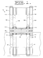
- cartridge assembly 14 includes a track pin 30, a bushing 32, first and second bearing members 34, 36, and first and second collars 38, 40.
- the track pin 30 defines a central longitudinal axis 42 and has a bore 44 concentrically positioned therethrough.
- a cross bore 46 extends from an outer surface 48 of the track pin 30 inward towards the bore 44 normal to the central longitudinal axis 42.
- Bushing 32 has a pair of end faces 50, an outer surface 54 and a stepped passage 56 concentrically positioned in respect to the outer surface 54.
- first bearing member 34 and first collar 38 are substantially identical to the second bearing member 36 and second collar 40, therefore only first bearing member 34 and first collar 38 will be described in detail herein.
- First bearing member 34 includes a first end portion 60, a second end portion 61, a bore 62 and an outer surface 63.
- the first end portion 60 extends radially outward away from the bore 62 and forms an abutting surface.
- a seal groove 64 is positioned in the second end portion 61 such that seal groove 64 is concentric with central longitudinal axis 42.
- the seal groove 64 has an outer wall segment 66 and an inner wall segment 68.
- Outer wall segment 66 is tapered outwardly with respect to the central longitudinal axis 42 at a predetermined angle. In a preferred the predetermined angle is about 5°.
- inner wall segment 68 is tapered inwardly with respect to central longitudinal axis 42. It should also be recognized that the inner wall segment 68 extends axially beyond the outer wall segment 66, the benefits of which will be described in more detail below.
- First seal arrangement 70 is shown positioned in the seal grove 64.
- First seal arrangement 70 includes an annular load ring 72 and a seal member 74.
- Annular load ring 72 is made from, for example, a polycarbonite compound and seal member 74 is made from, for example, polyurethane compound. Both the annular load ring 72 and the seal member 74 could however be made from other materials without altering the functional aspects of the design.
- Load ring 72 and seal member 74 are positioned in seal groove 64 so that load ring 72 urges seal member 74 in an axial direction outward from the seal groove 64.
- outer wall segment 66 Having outer wall segment 66 angled away from the central longitudinal axis 42 in the above described manner facilitates the insertion of load ring 72 and seal member 74 into seal groove 64.
- the predetermined angle of outer wall segment 66 enhances the installation capability of machinery utilized to insert first seal arrangement 70 into seal groove 64.
- First collar 38 includes a first end portion 80, a second end portion 81, a bore 82, and an outer surface 83.
- the first end portion 80 extends outward from the bore 82 and forms an outer radial surface.
- a seal groove 84 is positioned in the second end portion 81 such that seal groove 84 is concentric with central axis 42.
- the seal groove 84 has an outer wall segment 86.
- Wall segment 86 is tapered outwardly with respect to central longitudinal axis 42 at a predetermined angle similar to the outer wall segment 66 of the first bearing member 34. Again, in a preferred embodiment the predetermined angle is about 5°.
- Second seal arrangement 90 includes an annular load ring 94 and a seal member 96.
- Annular load ring 94 and seal member 96 are similar in composition and function to that of annular load member 72 and seal member 74 as described above.
- Load ring 94 and seal member 96 are positioned in seal groove 84 so that load ring 94 urges seal member 96 in an axial direction outward from the seal groove 84.
- seal groove 64 positioned in the bearing members 34, 36 and a seal groove 84 positioned in the collars 38, 40
- alternative positions for the seal grooves 64, 84 could be used.
- a seal groove may be positioned in each end face 50 of the track bushing 32, with each of the bearing members 34, 36 flipped end for end and the collars 38, 40 would be void of a seal groove 84.
- the bearing members 34, 36 may not have seal grooves and instead seal grooves only placed in the collars 38, 40 and each end face 60 of the track bushing 32 for comparable capability, function and results.
- a pair of plugs 100 are positioned in the bore 44 of the track pin 30 forming a fluid reservoir 102 in the bore 44 thereof.
- the pair of plugs 100 sealably prevents a fluid, such as lubricating oil, from leaking from the bore 44.
- fluid disposed within fluid reservoir 102 of the cartridge assembly 14 is in fluid communication with and advanced through cross bore 46 to the outer surface 48 of track pin 30. Once disposed on outer surface 48, the fluid facilitates the rotation of first and second bearing members 34, 36, and bushing 32 relative to track pin 30. Retention of the fluid within the cartridge assembly is assisted by first and second seal arrangements 70, 90, the first ends 60 of bearing members 34, 36, and the end faces 50 of the bushing 32 while keeping debris out (e.g. sand, dirt, etc).
- first and second seal arrangements 70, 90 the first ends 60 of bearing members 34, 36, and the end faces 50 of the bushing 32 while keeping debris out (e.g. sand, dirt, etc).
- the inner and outer link 16,18 and the inner and outer master links 22, 24 in this embodiment are shown as being straight links each having a first end portion 111 and a second end portion 113.
- the inner master link 22 is an exact duplicate the outer master link 24 therefore only inner master link 22 will be described in detail and the same elements will be represented by like numbers.
- inner and outer, in reference to links 16, 18 and master links 22, 24, in this example are used merely as descriptors for the orientation shown in the figures. Other terms such left, right and first, second could be interchangeably used as well.
- Inner link 22 includes a body portion 104 with a first side 106 and a second side 108 spaced opposite the first side 106.
- a first aperture 110 extends through the first end portion 111.
- a second aperture 112 extends through the second end portion 113.
- Body portion 104 also includes a rail surface 114 and a shoe surface 116.
- An aperture 120 is positioned on both sides of and a predetermined distance from a central vertical axis 122. It should be appreciated that each aperture 120 is laterally centered with respect to the widest portion of body portion 104.
- a fastener 124 is positioned in each of the aperture 120 and utilized to secure track shoe 20 to shoe surface 116 of inner master link 22.
- a gap 126 is formed between the first aperture 110 and the second aperture 112 extending through the body portion 104 from the first side 106 to the second side 108.
- the width of the gap 126 is reduced or pulled together, effectively reducing the diameter of the first and second aperture 110, 112.
- the first aperture 110 and the second aperture 112 are secured to the collars 38,40 of adjacent cartridge assemblies 14.
- the track chain assembly 10' includes a plurality of subassemblies 12'.
- Each subassembly 12' includes a cartridge assembly 14', an inner and outer link 16', 18' and a track shoe 20' connected to the inner and outer links 16', 18'.
- An inner and outer master link 22', 24' is used to connect opposite ends of the track chain assembly 10' to form a closed loop.
- Inner link 22' includes a body portion 104' having a first side 106', a second side 108', a first aperture 110', a second aperture 112', a rail surface 114', and a shoe surface 116'.
- Body member 104' also has an exit hole 130 interposed between first aperture 110' and second aperture 112'.
- An aperture 120' is positioned on either side of a vertical axis 122'. Apertures 120' are positioned at a predetermined angle with respect to the central vertical axis 122'.
- a fastener 124' is positioned in each of the apertures 120' and utilized to secure track shoe 20' to shoe surface 116' of inner master link 22'. Additionally, a gap 126' is positioned between the first aperture 110' and the second aperture 112' and extends through the exit hole 130 from the first side 106' to the second side 108'. As the fasteners 124' are tightened to secure the track shoe 20' to the inner and outer master links 22', 24' the diameter of the first and second aperture 110', 112' is effectively reduced. Thus, the first aperture 110' are secured to bearing members 34', 36' of one cartridge assembly 14' and the second aperture 112' are secured to the collars 38', 40' of an adjacent cartridge assembly 14'.
- the inner and outer links 16', 18' and the inner and outer master links 22', 24' are offset links. Therefore, this application would require a pair of inner master links 22' and a pair of outer master links 24'. In this manner, the first aperture 110' of an inner and outer master link 22', 24' is secured to the bearing members 34', 36' of one cartridge assembly 14' and the second aperture 112' of an adjacent inner and outer master link 22', 24' is secured to the collars 38', 40' of the same cartridge assembly 14'.
- the track chain assembly 10, 10' is assembled and operates as follows.
- the cartridge assembly 14, 14' can be preassembled prior to assembling the track chain 10, 10' in the following manner.
- the track pin 30 is inserted into the stepped passage 56 of bushing 32 such that bushing 32 can rotate relative to track pin 30.
- First seal arrangements 70 are inserted into the seal groove 64 of the bearing members 34, 36.
- the bearing members 34, 36 are positioned relative to track pin 28 until the inner wall segment 68 is positioned in close proximity to the end face 50 of bushing 32 with the seal groove 64 positioned adjacent to each end face 50 of bushing 32. This positions the seal member 74 to be urged against end face 50 of bushing 32.
- the bushing 32 and the bearing members 34, 36 are positioned along axial center of the track pin 30 so that a portion of the track pin 30 extends through bore 62 and beyond the first end portion 60. It should be appreciated that bearing members 34, 36 can rotate about the track pin 30 around axis 42 relative to both bushing 32 and track pin 30.
- Annular axial preload members 92 are positioned about the outer surface 48 of the track pin 30 adjacent to the first end portion 60 of the bearing members 34, 36.
- First seal arrangements 70 are inserted into the seal groove 84 of the collars 38, 40.
- the collars 38, 40 are positioned relative to track pin 30 and bearing member 34, 36 so that a portion of track pin 30 extends into bore 82 with the second end portion 81 of collars 38, 40 in an adjacent relationship to the first end portion 60 of bearing members 34, 36. This positions the seal member 94 to be urged against the first end portion 60 of each bearing member 34, 36.
- the annular axial preload member 92 controls the distance that the collars 38, 40 can be positioned inward toward bearing members 34, 36, and thus the bearing members 34, 36 moved inward toward the bushing 32.
- collars 38, 40 are fixed relative to track pin 30 so that collars 38, 40 will not rotate or move axially relative to track pin 30.
- collars 38, 40 can be press fit onto, laser welded to, adhesive or chemically bonded to the track pin 30 or any other known manner of attaching two mechanical components. Attaching collars 38, 40 to track pin 30 helps control end play of track chain assembly 10, 10'.
- each subassembly 12 includes a cartridge assembly 14, an inner link 16, an outer link 18 and a track shoe 20 fastened to the shoe surface 116 of the inner and outer links 16, 18.
- one sub assembly is completed by positioning inner link 16 relative to cartridge assembly 14 such that bearing member 34 of cartridge assembly 14 is located within aperture 112 of inner link 16, bearing member 36 of cartridge assembly 14 is located within aperture 112 of outer link 18.
- the combination of the inner link 16, outer link 18 and the cartridge assembly 14 forms a subassembly 12.
- the next adjacent subassembly 12 would be an outer subassembly 12, comprised of identical components that have the inner link 16 positioned relative to cartridge assembly 14 so that collar 38 is located within aperture 110 of inner link 16 and collar 40 is located within aperture 110 of outer link 18. It should be appreciated that bearing members 34, 36 and collars 38, 40 are press fit into apertures 110 and 112 of the inner and outer links 16, 18. Additionally, the inner links 16 and outer links 18 of adjacent sub assemblies 12 are positioned with a predetermined space therebetween, preferably the predetermined space is 1.5mm.
- the outer sub assembly 12 is fixed relative to collars 38, 40 and the track pin 30, with an inner subassembly 12 fixed relative to bearing members 34, 36. This allows the inner subassembly 12 to move relative to the track pin 30 and bushing 32, while the outer subassembly 12 is fixed relative to the track pin 30 but free to pivot relative to the bearing members 34, 36 and the track bushing 32.
- each subassembly 12' includes a cartridge assembly 14', an inner link 16', an outer link 18' and a track shoe 20' fastened to the shoe surface 116' of the inner and outer links 16', 18'.
- one sub assembly is completed by positioning inner link 16' relative to cartridge assembly 14' such that bearing member 34' of cartridge assembly 14' is located within aperture 110' of inner link 16', bearing member 36' of cartridge assembly 14' is located within aperture 110' of outer link 18' forming a sub assembly 12'.
- Two adjacent subassemblies 12' are secured together by placing collar 38' within aperture 112' of the inner link 16' and collar 40'within aperture 112' of outer link 18'.
- bearing members 34', 36' are press fit into apertures 110' and collars 38', 40' are press fit into apertures 112' of the inner and outer links 16', 18'.
- the first end portion 111' of each inner and outer link 16', 18' is fixed relative to bearing members 34', 36' and the second end portion 113' of the inner and outer links 16', 18' fixed relative collars 38', 40' and the track pin 30' of an adjacent an sub assembly 12'.
- connection subassemblies 12' is continued until an appropriate number of adjacent subassemblies 12' are connected together to form a track chain assembly 10' of a given length.
- two inner and outer master links 22', 24' are required to connect the ends of the track chain assembly 10' of this embodiment together.
- Apertures 110' of the first end portion 111' of an inner and an outer master link 22', 24' are positioned around the bearing member 34', 36' of a cartridge assembly 14'.
- Apertures 112' of the second end portion 113' of an adjacent set of inner and outer master links 22', 24' are positioned around collars 38', 40' of the same cartridge assembly 14'.
- the last two track shoes 20' are then fastened to the shoe surface 116' of the two adjacent sets of inner and outer master links 22', 24'.
- By tightening fasteners 124' the width of the gap 126 is reduced or pulled together effectively reducing the diameter of the first and second apertures 110', 112', securing the first apertures 110' to the bearing members 34', 36' and the second apertures 112' to the collars 38', 40' of the same cartridge assembly 14'.
- Disconnecting the ends of the track chain assembly 10' of this embodiment requires loosening the fasteners 124' of the adjacent sets of inner and outer master links 22', 24', this allows a single cartridge assembly 14' to be removed and the ends of the track chain assembly 10' to be separated.
Landscapes
- Engineering & Computer Science (AREA)
- Chemical & Material Sciences (AREA)
- Combustion & Propulsion (AREA)
- Transportation (AREA)
- Mechanical Engineering (AREA)
- Sealing Devices (AREA)
- Devices For Conveying Motion By Means Of Endless Flexible Members (AREA)
Abstract
Description
Claims (8)
- A cartridge assembly (14) for a track chain (10), comprising:a track pin (30) defining a longitudinal axis (42) and having a bore (44) positioned therethrough;a bushing (32) having a pair of end faces (50) and a passage (56) defined therethrough and being rotatably positioned about said track pin (30);bearing members (34,36) having a first end portion (60), a second end portion (61) and a bore (62) defined therethrough, said bearing members (34,36) positioned about said track pin (30) so that the second end portion (61) of each of said bearing members (34,36) being adjacent said bushing (32);collars (38,40) having a first end portion (80), a second end portion (81) and a bore (82) defined therethrough, said collars (38,40) being positioned about said track pin (30) so that the second end portion (81) of each of said collars (38,40) being adjacent the first end portion (61) of each of said bearing members (34,36);a first seal arrangement (70) positioned in at least one said pair of end faces (50) of said bushing (32) and said second end portion (61) of each of said bearing members (34,36); anda second seal arrangement (90) positioned in at least one of said first end portion (60) of each of said bearing members (34,36) and said second end portion (81) of each of said collars (38,40).
- The cartridge assembly (14) of claim 1, wherein said collars (38,40) are fixed in relation to said track pin (30) such that said collars (38,40) are unable to rotate relative to said track pin (30) and said bearing members (34,36) are able to rotate relative to said collars (38,40) and said track pin (30) around said longitudinal axis (42).
- The cartridge assembly (14) of claim 1, wherein said bearing members (34,36) are able to rotate relative to said bushing (32) around said longitudinal axis (42).
- The cartridge assembly (14) of claim 1, wherein preload on a load ring (72) of said first seal arrangement (70) is controlled by a first wall segment (68) of a seal groove (64) positioned in a one said pair of end faces (50) of said bushing (32) and said second end portion (61) of each of said bearing members (34,36).
- The cartridge assembly (14) of claim 1, wherein preload on a load member (94) of said second seal arrangement (90) is controlled by an annular axial thrust member (92) positioned between a one of said first end portion (60) of each of said bearing members (34,36) and said second end portion (81) of each of said collars (38,40).
- The cartridge assembly (14) of claim 1, wherein said track pin (30) has a fluid reservoir (102) defined therein.
- The cartridge assembly (14) of claim 6, wherein said fluid reservoir (102) being in fluid communication with an outer surface (48) of said track pin (30) and the passage (56) of said bushing (32).
- The cartridge assembly (14) of claim 1, wherein said bearing (34,36) members each have an annular seal groove (64) positioned in the second end portion (61) thereof such that said annular seal groove (64) surrounds said track pin (30).
Applications Claiming Priority (2)
| Application Number | Priority Date | Filing Date | Title |
|---|---|---|---|
| US10/224,843 US6739680B2 (en) | 2002-08-21 | 2002-08-21 | Cartridge assembly for a track chain |
| US224843 | 2002-08-21 |
Publications (2)
| Publication Number | Publication Date |
|---|---|
| EP1391372A2 true EP1391372A2 (en) | 2004-02-25 |
| EP1391372A3 EP1391372A3 (en) | 2005-03-02 |
Family
ID=31187981
Family Applications (1)
| Application Number | Title | Priority Date | Filing Date |
|---|---|---|---|
| EP03015855A Withdrawn EP1391372A3 (en) | 2002-08-21 | 2003-07-11 | Cartridge assembly for a track chain |
Country Status (3)
| Country | Link |
|---|---|
| US (1) | US6739680B2 (en) |
| EP (1) | EP1391372A3 (en) |
| JP (1) | JP2004075063A (en) |
Cited By (2)
| Publication number | Priority date | Publication date | Assignee | Title |
|---|---|---|---|---|
| CN102639389A (en) * | 2009-11-09 | 2012-08-15 | 卡特彼勒公司 | Bushing for tracked undercarriages |
| IT202400001731A1 (en) * | 2024-01-30 | 2025-07-30 | Usco S P A | TRACK ELEMENT WITH ROTATING BUSH CARTRIDGE |
Families Citing this family (29)
| Publication number | Priority date | Publication date | Assignee | Title |
|---|---|---|---|---|
| US7347513B2 (en) * | 2005-06-20 | 2008-03-25 | Caterpillar Inc. | Cartridge assembly for a track chain of a track type machine and machine using same |
| US7766433B2 (en) * | 2006-09-22 | 2010-08-03 | Deere & Company | Cartridge for use as joint in endless track chain and associated method |
| US7597410B2 (en) * | 2007-03-23 | 2009-10-06 | Deere & Company | Track chain joint with radial seal unit |
| US20080265667A1 (en) * | 2007-04-24 | 2008-10-30 | Livesay Richard E | Bolt together machine track and method |
| US7959239B2 (en) | 2008-03-25 | 2011-06-14 | Caterpillar Inc. | Track assembly having wear inhibiting contact members |
| US7850256B2 (en) * | 2008-10-24 | 2010-12-14 | Deere & Company | Dual-bushing track chain cartridge |
| US7877977B2 (en) * | 2008-12-12 | 2011-02-01 | Caterpillar Inc. | Master link for a track chain |
| US8336970B2 (en) * | 2008-12-16 | 2012-12-25 | Caterpillar Inc. | Link and link assembly for track-type machine |
| US8070241B2 (en) * | 2009-08-27 | 2011-12-06 | Deere & Company | Track chain joint with rotatable pin |
| US20110079451A1 (en) * | 2009-10-01 | 2011-04-07 | Caterpillar, Inc. | Strength Track Bushing |
| US9073589B2 (en) * | 2009-10-23 | 2015-07-07 | Caterpillar Inc. | Pin joint component with improved wear surfaces |
| DE102009058216B4 (en) * | 2009-12-15 | 2014-09-04 | Aktiebolaget Skf | Sealing arrangement and joint of a chain with the seal assembly |
| US8721213B2 (en) | 2010-03-31 | 2014-05-13 | Caterpillar Inc. | Seal assembly for track pin joint assembly |
| US8678696B2 (en) | 2010-03-31 | 2014-03-25 | Caterpillar Inc. | Seal assembly for track pin joint assembly |
| WO2011136135A1 (en) * | 2010-04-28 | 2011-11-03 | 株式会社小松製作所 | Crawler track and master link for crawler track |
| US20120119567A1 (en) * | 2010-11-16 | 2012-05-17 | Caterpillar, Inc. | Cartridge Seal for Track Chain Bushing |
| US20120267947A1 (en) * | 2011-04-22 | 2012-10-25 | Caterpillar, Inc. | Twin Bushing Track Chain Cartridge |
| US8985590B2 (en) | 2011-04-22 | 2015-03-24 | Caterpillar | Seal assembly for track pin joint assembly of undercarriage |
| US9126645B2 (en) | 2011-06-28 | 2015-09-08 | Caterpillar Inc. | Track chain cartridge having thrust bearings |
| US9327783B1 (en) | 2013-05-07 | 2016-05-03 | Deere & Company | Cartridge joint with convoluted seal |
| US9623920B2 (en) | 2013-08-29 | 2017-04-18 | Caterpillar Inc. | Track joint assemblies |
| US9505453B2 (en) | 2013-08-29 | 2016-11-29 | Caterpillar Inc. | Track joint assemblies |
| US9604681B2 (en) | 2013-08-29 | 2017-03-28 | Caterpillar Inc. | Track joint assemblies |
| US9434425B2 (en) | 2013-08-29 | 2016-09-06 | Caterpillar Inc. | Track joint assemblies |
| US10040495B2 (en) | 2015-12-08 | 2018-08-07 | Caterpillar Inc. | Laser brazing of annular metal seal member on track link |
| US10046816B2 (en) * | 2016-07-07 | 2018-08-14 | Caterpillar Inc. | Cartridge assembly with a flexible thrust ring assembly for a track chain |
| US10457343B2 (en) | 2016-10-07 | 2019-10-29 | Caterpillar Inc. | Track chain assembly of undercarriage with link having increased pitch |
| JP6730920B2 (en) * | 2016-12-28 | 2020-07-29 | 株式会社小松製作所 | Crawler belt bearing bush and method of manufacturing the same |
| US20190351959A1 (en) * | 2018-05-18 | 2019-11-21 | Caterpillar Inc. | Master link assembly for an offset link track chain |
Family Cites Families (20)
| Publication number | Priority date | Publication date | Assignee | Title |
|---|---|---|---|---|
| BE491072A (en) | 1948-10-07 | |||
| US2780830A (en) | 1955-06-20 | 1957-02-12 | Jr Archer W Kammerer | Pin retainer |
| US3409336A (en) | 1966-12-21 | 1968-11-05 | Caterpillar Tractor Co | Sealed track joint for crawler vehicles |
| US3463560A (en) | 1967-10-23 | 1969-08-26 | Caterpillar Tractor Co | Self-contained,sealed and lubricated hinge joint |
| US3492054A (en) * | 1967-12-29 | 1970-01-27 | Caterpillar Tractor Co | Track hinge joints with rotating bushings |
| US3601454A (en) | 1969-06-19 | 1971-08-24 | Caterpillar Tractor Co | Cartridge joint for heavy duty track chain |
| US3680924A (en) | 1970-03-06 | 1972-08-01 | Us Army | Endless track pin assembly |
| US3958836A (en) * | 1975-01-09 | 1976-05-25 | Brown Cicero C | Movable track assembly for drive tracks |
| US4120537A (en) * | 1977-04-15 | 1978-10-17 | Caterpillar Tractor Co. | Track link assembly having roller bushings |
| US4126359A (en) | 1977-06-15 | 1978-11-21 | Caterpillar Tractor Co. | Torsional track bushing |
| US4095909A (en) | 1977-07-11 | 1978-06-20 | Caterpillar Tractor Co. | Cartridge pin mounting |
| US4324437A (en) | 1978-05-12 | 1982-04-13 | Narang Rajendra K | Endless track |
| DE3609334A1 (en) | 1986-03-20 | 1987-09-24 | Schaeffler Waelzlager Kg | TRACK CHAIN |
| US5183318A (en) * | 1991-11-26 | 1993-02-02 | Caterpillar Inc. | Endless track chain for track-type vehicles |
| JP3683060B2 (en) * | 1996-12-13 | 2005-08-17 | 株式会社小松製作所 | Tracked vehicle tracked vehicle |
| DE19752391C1 (en) * | 1997-11-26 | 1999-05-27 | Intertractor Zweigniederlassun | Track for endless track vehicle |
| US6564539B2 (en) * | 1999-12-09 | 2003-05-20 | Caterpillar Inc | Method and apparatus for retaining a track chain joint |
| US6386651B1 (en) * | 2000-04-20 | 2002-05-14 | Caterpillar Inc. | Insert arrangement for a track chain assembly |
| US6382742B1 (en) | 2000-04-20 | 2002-05-07 | Caterpillar Inc. | Cartridge assembly for a track chain of a track type work machine |
| US6783196B2 (en) * | 2002-08-13 | 2004-08-31 | Caterpillar Inc | Master link for a track chain |
-
2002
- 2002-08-21 US US10/224,843 patent/US6739680B2/en not_active Expired - Lifetime
-
2003
- 2003-07-11 EP EP03015855A patent/EP1391372A3/en not_active Withdrawn
- 2003-08-13 JP JP2003293011A patent/JP2004075063A/en active Pending
Cited By (5)
| Publication number | Priority date | Publication date | Assignee | Title |
|---|---|---|---|---|
| CN102639389A (en) * | 2009-11-09 | 2012-08-15 | 卡特彼勒公司 | Bushing for tracked undercarriages |
| EP2499039A4 (en) * | 2009-11-09 | 2013-06-26 | Caterpillar Inc | Bushing for tracked undercarriages |
| CN102639389B (en) * | 2009-11-09 | 2015-03-11 | 卡特彼勒公司 | Bushing for tracked undercarriages |
| IT202400001731A1 (en) * | 2024-01-30 | 2025-07-30 | Usco S P A | TRACK ELEMENT WITH ROTATING BUSH CARTRIDGE |
| WO2025163546A1 (en) * | 2024-01-30 | 2025-08-07 | Usco S.P.A. | Track member with rotating bushing cartridge |
Also Published As
| Publication number | Publication date |
|---|---|
| JP2004075063A (en) | 2004-03-11 |
| US6739680B2 (en) | 2004-05-25 |
| EP1391372A3 (en) | 2005-03-02 |
| US20040036353A1 (en) | 2004-02-26 |
Similar Documents
| Publication | Publication Date | Title |
|---|---|---|
| US6739680B2 (en) | Cartridge assembly for a track chain | |
| EP1391371B1 (en) | Master link for a track chain | |
| US5887958A (en) | Track link assembly having positive pin retention | |
| JP5059998B2 (en) | Crawler chain cartridge assembly for crawler work machines | |
| US7597410B2 (en) | Track chain joint with radial seal unit | |
| JP5059999B2 (en) | Insert device for crawler chain assembly | |
| US7959239B2 (en) | Track assembly having wear inhibiting contact members | |
| CA2775238C (en) | Seal assembly for track pin joint assembly of undercarriage | |
| JP5220971B2 (en) | Crawler chain link for crawler work machines | |
| JPH10167131A (en) | Tracked equipment for tracked vehicles | |
| KR20080034098A (en) | Cartridge assembly for track chains in track type work machines and working machines using it | |
| CA3126711C (en) | Sealing system for a track | |
| EP3481706B1 (en) | Cartridge assembly with a flexible thrust ring assembly for a track chain | |
| US3463560A (en) | Self-contained,sealed and lubricated hinge joint | |
| US9745005B2 (en) | Roller assembly for a track-type machine | |
| KR102674848B1 (en) | Link assembly with threaded master pin | |
| KR20010015293A (en) | Chain for forming tracks | |
| US4239297A (en) | Radial face seal |
Legal Events
| Date | Code | Title | Description |
|---|---|---|---|
| PUAI | Public reference made under article 153(3) epc to a published international application that has entered the european phase |
Free format text: ORIGINAL CODE: 0009012 |
|
| AK | Designated contracting states |
Kind code of ref document: A2 Designated state(s): AT BE BG CH CY CZ DE DK EE ES FI FR GB GR HU IE IT LI LU MC NL PT RO SE SI SK TR |
|
| AX | Request for extension of the european patent |
Extension state: AL LT LV MK |
|
| PUAL | Search report despatched |
Free format text: ORIGINAL CODE: 0009013 |
|
| AK | Designated contracting states |
Kind code of ref document: A3 Designated state(s): AT BE BG CH CY CZ DE DK EE ES FI FR GB GR HU IE IT LI LU MC NL PT RO SE SI SK TR |
|
| AX | Request for extension of the european patent |
Extension state: AL LT LV MK |
|
| 17P | Request for examination filed |
Effective date: 20050902 |
|
| AKX | Designation fees paid |
Designated state(s): DE IT |
|
| STAA | Information on the status of an ep patent application or granted ep patent |
Free format text: STATUS: THE APPLICATION HAS BEEN WITHDRAWN |
|
| 18W | Application withdrawn |
Effective date: 20070808 |