EP1389974B1 - Method for attaching axial filaments to a self expanding stent - Google Patents
Method for attaching axial filaments to a self expanding stent Download PDFInfo
- Publication number
- EP1389974B1 EP1389974B1 EP02719207A EP02719207A EP1389974B1 EP 1389974 B1 EP1389974 B1 EP 1389974B1 EP 02719207 A EP02719207 A EP 02719207A EP 02719207 A EP02719207 A EP 02719207A EP 1389974 B1 EP1389974 B1 EP 1389974B1
- Authority
- EP
- European Patent Office
- Prior art keywords
- stent
- filament
- adhesive
- stent body
- threads
- Prior art date
- Legal status (The legal status is an assumption and is not a legal conclusion. Google has not performed a legal analysis and makes no representation as to the accuracy of the status listed.)
- Expired - Lifetime
Links
- 238000000034 method Methods 0.000 title claims description 17
- 239000000853 adhesive Substances 0.000 claims description 53
- 230000001070 adhesive effect Effects 0.000 claims description 53
- 229920000642 polymer Polymers 0.000 claims description 14
- 239000002904 solvent Substances 0.000 claims description 11
- 230000000284 resting effect Effects 0.000 claims description 5
- 238000004519 manufacturing process Methods 0.000 claims description 4
- 238000005507 spraying Methods 0.000 claims description 2
- 238000001704 evaporation Methods 0.000 claims 3
- 230000006835 compression Effects 0.000 claims 2
- 238000007906 compression Methods 0.000 claims 2
- 238000007598 dipping method Methods 0.000 claims 1
- 239000000463 material Substances 0.000 description 26
- 229920001971 elastomer Polymers 0.000 description 11
- 239000000806 elastomer Substances 0.000 description 11
- 239000003292 glue Substances 0.000 description 8
- 229920003225 polyurethane elastomer Polymers 0.000 description 8
- 210000004204 blood vessel Anatomy 0.000 description 6
- 239000004814 polyurethane Substances 0.000 description 5
- 208000031481 Pathologic Constriction Diseases 0.000 description 4
- 229920001577 copolymer Polymers 0.000 description 4
- 238000013461 design Methods 0.000 description 4
- 230000002708 enhancing effect Effects 0.000 description 4
- 238000002513 implantation Methods 0.000 description 4
- 229920001296 polysiloxane Polymers 0.000 description 4
- 229920002635 polyurethane Polymers 0.000 description 4
- JVTAAEKCZFNVCJ-UWTATZPHSA-N D-lactic acid Chemical compound C[C@@H](O)C(O)=O JVTAAEKCZFNVCJ-UWTATZPHSA-N 0.000 description 3
- YMWUJEATGCHHMB-UHFFFAOYSA-N Dichloromethane Chemical compound ClCCl YMWUJEATGCHHMB-UHFFFAOYSA-N 0.000 description 3
- 229920002334 Spandex Polymers 0.000 description 3
- 239000011248 coating agent Substances 0.000 description 3
- 238000000576 coating method Methods 0.000 description 3
- 229940022769 d- lactic acid Drugs 0.000 description 3
- 239000003814 drug Substances 0.000 description 3
- 229940079593 drug Drugs 0.000 description 3
- 230000006870 function Effects 0.000 description 3
- 230000001965 increasing effect Effects 0.000 description 3
- 238000003780 insertion Methods 0.000 description 3
- 230000037431 insertion Effects 0.000 description 3
- 239000004759 spandex Substances 0.000 description 3
- 208000037804 stenosis Diseases 0.000 description 3
- 230000036262 stenosis Effects 0.000 description 3
- 239000000126 substance Substances 0.000 description 3
- 239000013589 supplement Substances 0.000 description 3
- 230000000153 supplemental effect Effects 0.000 description 3
- VPVXHAANQNHFSF-UHFFFAOYSA-N 1,4-dioxan-2-one Chemical compound O=C1COCCO1 VPVXHAANQNHFSF-UHFFFAOYSA-N 0.000 description 2
- DSUFPYCILZXJFF-UHFFFAOYSA-N 4-[[4-[[4-(pentoxycarbonylamino)cyclohexyl]methyl]cyclohexyl]carbamoyloxy]butyl n-[4-[[4-(butoxycarbonylamino)cyclohexyl]methyl]cyclohexyl]carbamate Chemical compound C1CC(NC(=O)OCCCCC)CCC1CC1CCC(NC(=O)OCCCCOC(=O)NC2CCC(CC3CCC(CC3)NC(=O)OCCCC)CC2)CC1 DSUFPYCILZXJFF-UHFFFAOYSA-N 0.000 description 2
- 229920000331 Polyhydroxybutyrate Polymers 0.000 description 2
- 230000004075 alteration Effects 0.000 description 2
- TZCXTZWJZNENPQ-UHFFFAOYSA-L barium sulfate Chemical compound [Ba+2].[O-]S([O-])(=O)=O TZCXTZWJZNENPQ-UHFFFAOYSA-L 0.000 description 2
- 238000009954 braiding Methods 0.000 description 2
- 230000015556 catabolic process Effects 0.000 description 2
- 238000006731 degradation reaction Methods 0.000 description 2
- 238000005516 engineering process Methods 0.000 description 2
- 239000000835 fiber Substances 0.000 description 2
- 239000000945 filler Substances 0.000 description 2
- 230000006872 improvement Effects 0.000 description 2
- 238000011065 in-situ storage Methods 0.000 description 2
- 230000007246 mechanism Effects 0.000 description 2
- 239000002184 metal Substances 0.000 description 2
- 229910001092 metal group alloy Inorganic materials 0.000 description 2
- 238000012986 modification Methods 0.000 description 2
- 230000004048 modification Effects 0.000 description 2
- HLXZNVUGXRDIFK-UHFFFAOYSA-N nickel titanium Chemical compound [Ti].[Ti].[Ti].[Ti].[Ti].[Ti].[Ti].[Ti].[Ti].[Ti].[Ti].[Ni].[Ni].[Ni].[Ni].[Ni].[Ni].[Ni].[Ni].[Ni].[Ni].[Ni].[Ni].[Ni].[Ni] HLXZNVUGXRDIFK-UHFFFAOYSA-N 0.000 description 2
- 229910001000 nickel titanium Inorganic materials 0.000 description 2
- 229920001432 poly(L-lactide) Polymers 0.000 description 2
- 239000005015 poly(hydroxybutyrate) Substances 0.000 description 2
- -1 poly(lactic acid-ethylene oxide) copolymers Polymers 0.000 description 2
- 229920001610 polycaprolactone Polymers 0.000 description 2
- 239000004632 polycaprolactone Substances 0.000 description 2
- 229920002795 polyhydroxyoctanoate Polymers 0.000 description 2
- 229920002379 silicone rubber Polymers 0.000 description 2
- 238000004804 winding Methods 0.000 description 2
- RKDVKSZUMVYZHH-UHFFFAOYSA-N 1,4-dioxane-2,5-dione Chemical compound O=C1COC(=O)CO1 RKDVKSZUMVYZHH-UHFFFAOYSA-N 0.000 description 1
- OVSKIKFHRZPJSS-UHFFFAOYSA-N 2,4-D Chemical compound OC(=O)COC1=CC=C(Cl)C=C1Cl OVSKIKFHRZPJSS-UHFFFAOYSA-N 0.000 description 1
- 239000004970 Chain extender Substances 0.000 description 1
- 229930182843 D-Lactic acid Natural products 0.000 description 1
- 229920001736 Metabolix Polymers 0.000 description 1
- 229920000954 Polyglycolide Polymers 0.000 description 1
- 239000012790 adhesive layer Substances 0.000 description 1
- 229910045601 alloy Inorganic materials 0.000 description 1
- 239000000956 alloy Substances 0.000 description 1
- 230000004323 axial length Effects 0.000 description 1
- 210000000013 bile duct Anatomy 0.000 description 1
- 239000012620 biological material Substances 0.000 description 1
- 230000015572 biosynthetic process Effects 0.000 description 1
- 210000001124 body fluid Anatomy 0.000 description 1
- 239000010839 body fluid Substances 0.000 description 1
- 230000036760 body temperature Effects 0.000 description 1
- 210000000621 bronchi Anatomy 0.000 description 1
- 239000000919 ceramic Substances 0.000 description 1
- 229910002110 ceramic alloy Inorganic materials 0.000 description 1
- 238000012668 chain scission Methods 0.000 description 1
- 210000001072 colon Anatomy 0.000 description 1
- 150000001875 compounds Chemical class 0.000 description 1
- 230000003247 decreasing effect Effects 0.000 description 1
- 230000010339 dilation Effects 0.000 description 1
- 230000005489 elastic deformation Effects 0.000 description 1
- 238000002474 experimental method Methods 0.000 description 1
- 230000003301 hydrolyzing effect Effects 0.000 description 1
- 239000007943 implant Substances 0.000 description 1
- 238000009434 installation Methods 0.000 description 1
- JJTUDXZGHPGLLC-UHFFFAOYSA-N lactide Chemical compound CC1OC(=O)C(C)OC1=O JJTUDXZGHPGLLC-UHFFFAOYSA-N 0.000 description 1
- 239000007788 liquid Substances 0.000 description 1
- 229920002529 medical grade silicone Polymers 0.000 description 1
- 229910052751 metal Inorganic materials 0.000 description 1
- 150000002739 metals Chemical class 0.000 description 1
- 239000000203 mixture Substances 0.000 description 1
- 229920003023 plastic Polymers 0.000 description 1
- 239000004033 plastic Substances 0.000 description 1
- 229920000747 poly(lactic acid) Polymers 0.000 description 1
- 229920002463 poly(p-dioxanone) polymer Polymers 0.000 description 1
- 239000000622 polydioxanone Substances 0.000 description 1
- 239000004633 polyglycolic acid Substances 0.000 description 1
- 239000004626 polylactic acid Substances 0.000 description 1
- 239000000843 powder Substances 0.000 description 1
- 125000002924 primary amino group Chemical group [H]N([H])* 0.000 description 1
- 239000012781 shape memory material Substances 0.000 description 1
- 238000005728 strengthening Methods 0.000 description 1
- 230000000930 thermomechanical effect Effects 0.000 description 1
- 229920002725 thermoplastic elastomer Polymers 0.000 description 1
- 210000003437 trachea Anatomy 0.000 description 1
- YFHICDDUDORKJB-UHFFFAOYSA-N trimethylene carbonate Chemical compound O=C1OCCCO1 YFHICDDUDORKJB-UHFFFAOYSA-N 0.000 description 1
- 210000000626 ureter Anatomy 0.000 description 1
- 210000003708 urethra Anatomy 0.000 description 1
- PAPBSGBWRJIAAV-UHFFFAOYSA-N ε-Caprolactone Chemical compound O=C1CCCCCO1 PAPBSGBWRJIAAV-UHFFFAOYSA-N 0.000 description 1
Images


Classifications
-
- A—HUMAN NECESSITIES
- A61—MEDICAL OR VETERINARY SCIENCE; HYGIENE
- A61F—FILTERS IMPLANTABLE INTO BLOOD VESSELS; PROSTHESES; DEVICES PROVIDING PATENCY TO, OR PREVENTING COLLAPSING OF, TUBULAR STRUCTURES OF THE BODY, e.g. STENTS; ORTHOPAEDIC, NURSING OR CONTRACEPTIVE DEVICES; FOMENTATION; TREATMENT OR PROTECTION OF EYES OR EARS; BANDAGES, DRESSINGS OR ABSORBENT PADS; FIRST-AID KITS
- A61F2/00—Filters implantable into blood vessels; Prostheses, i.e. artificial substitutes or replacements for parts of the body; Appliances for connecting them with the body; Devices providing patency to, or preventing collapsing of, tubular structures of the body, e.g. stents
- A61F2/82—Devices providing patency to, or preventing collapsing of, tubular structures of the body, e.g. stents
- A61F2/86—Stents in a form characterised by the wire-like elements; Stents in the form characterised by a net-like or mesh-like structure
- A61F2/90—Stents in a form characterised by the wire-like elements; Stents in the form characterised by a net-like or mesh-like structure characterised by a net-like or mesh-like structure
-
- A—HUMAN NECESSITIES
- A61—MEDICAL OR VETERINARY SCIENCE; HYGIENE
- A61F—FILTERS IMPLANTABLE INTO BLOOD VESSELS; PROSTHESES; DEVICES PROVIDING PATENCY TO, OR PREVENTING COLLAPSING OF, TUBULAR STRUCTURES OF THE BODY, e.g. STENTS; ORTHOPAEDIC, NURSING OR CONTRACEPTIVE DEVICES; FOMENTATION; TREATMENT OR PROTECTION OF EYES OR EARS; BANDAGES, DRESSINGS OR ABSORBENT PADS; FIRST-AID KITS
- A61F2/00—Filters implantable into blood vessels; Prostheses, i.e. artificial substitutes or replacements for parts of the body; Appliances for connecting them with the body; Devices providing patency to, or preventing collapsing of, tubular structures of the body, e.g. stents
- A61F2/82—Devices providing patency to, or preventing collapsing of, tubular structures of the body, e.g. stents
- A61F2002/825—Devices providing patency to, or preventing collapsing of, tubular structures of the body, e.g. stents having longitudinal struts
-
- A—HUMAN NECESSITIES
- A61—MEDICAL OR VETERINARY SCIENCE; HYGIENE
- A61F—FILTERS IMPLANTABLE INTO BLOOD VESSELS; PROSTHESES; DEVICES PROVIDING PATENCY TO, OR PREVENTING COLLAPSING OF, TUBULAR STRUCTURES OF THE BODY, e.g. STENTS; ORTHOPAEDIC, NURSING OR CONTRACEPTIVE DEVICES; FOMENTATION; TREATMENT OR PROTECTION OF EYES OR EARS; BANDAGES, DRESSINGS OR ABSORBENT PADS; FIRST-AID KITS
- A61F2210/00—Particular material properties of prostheses classified in groups A61F2/00 - A61F2/26 or A61F2/82 or A61F9/00 or A61F11/00 or subgroups thereof
- A61F2210/0004—Particular material properties of prostheses classified in groups A61F2/00 - A61F2/26 or A61F2/82 or A61F9/00 or A61F11/00 or subgroups thereof bioabsorbable
-
- A—HUMAN NECESSITIES
- A61—MEDICAL OR VETERINARY SCIENCE; HYGIENE
- A61F—FILTERS IMPLANTABLE INTO BLOOD VESSELS; PROSTHESES; DEVICES PROVIDING PATENCY TO, OR PREVENTING COLLAPSING OF, TUBULAR STRUCTURES OF THE BODY, e.g. STENTS; ORTHOPAEDIC, NURSING OR CONTRACEPTIVE DEVICES; FOMENTATION; TREATMENT OR PROTECTION OF EYES OR EARS; BANDAGES, DRESSINGS OR ABSORBENT PADS; FIRST-AID KITS
- A61F2250/00—Special features of prostheses classified in groups A61F2/00 - A61F2/26 or A61F2/82 or A61F9/00 or A61F11/00 or subgroups thereof
- A61F2250/0014—Special features of prostheses classified in groups A61F2/00 - A61F2/26 or A61F2/82 or A61F9/00 or A61F11/00 or subgroups thereof having different values of a given property or geometrical feature, e.g. mechanical property or material property, at different locations within the same prosthesis
- A61F2250/0048—Special features of prostheses classified in groups A61F2/00 - A61F2/26 or A61F2/82 or A61F9/00 or A61F11/00 or subgroups thereof having different values of a given property or geometrical feature, e.g. mechanical property or material property, at different locations within the same prosthesis differing in mechanical expandability, e.g. in mechanical, self- or balloon expandability
Definitions
- the invention pertains to self-expanding stents and particularly to methods of attaching axial filaments to the stent body to increase its radial expansion force.
- a stent essentially is a hollow tube that supplements the body vessel. With respect to the medical condition of stenosis, in which a body lumen tends to collapse or otherwise close, the stent supports the wall of the vessel to prevent it from collapsing or closing.
- a blood vessel that is narrowed due to the build up of intra-vascular plaque is one example of a stenosis.
- the stent serves essentially the opposite function in that it substitutes for or supplements a weakened portion of the vessel.
- Stents are known for insertion in blood vessels, bile ducts, colons, trachea, bronchi, esophagi, urethra, ureters, etc.
- stents are commercially available at this time. Most stents need to be radially constricted, i.e., reduced in diameter, so that they can be inserted into the body lumen. Once they are in situ, the stent can be radially expanded to the desired diameter. Stents are known that are fabricated from rigid, but deformable materials that, when bent by force, tend to retain the bent shape. Such stents may be inserted into the body lumen in an unstressed radially minimal shape while mounted over a deflated balloon. When the stent is in situ, the balloon is inflated in order to radially expand the stent, which will then retain the radially expanded shape after the balloon is deflated and removed.
- Self-expanding stents can be compressed radially, but will expand to their original shape once the radially constricting force is removed.
- Some types of self-expanding stent are formed from materials that are superelastic or have shape memory characteristics.
- Such stents are commonly made of Nitinol, a biocompatible alloy that, depending on its chemical composition and thermomechanical history, may be used either as a shape memory material or a superelastic material.
- the Ultraflex stent manufactured and sold by Boston Scientific Corporation is an example of a knitted Nitinol stent.
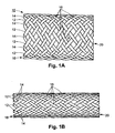
- a first subset of the flexible thread elements 12 have the same direction of winding and are displaced relative to each other about the cylindrical surface of the stent. They cross a second plurality of helical thread elements 14 which are also displaced relative to each other about the cylindrical surface of the stent, but having the opposite direction of winding. Accordingly, as shown in Figure 1A, the threads 12 of the first subset cross the threads 14 of the second subset at crossing points 16.
- Figure 1A illustrates an embodiment in which the crossing threads are fully interlaced, however, the crossing threads may be interlaced at other intervals, e.g., every other crossing point or every third crossing point.
- the diameter reduces, as shown in Figure 1B.
- the wall of the stent is constricted so as to reduce the stent's diameter, the stent elongates. In other words, radial constriction and axial elongation go hand in hand.
- the stent tends to spring back to its resting diameter and length.
- the force with which the stent returns to its original state depends on many factors, including the rigidity of the individual threads, the number of threads, and the original (resting) crossing angle, ⁇ , of the threads.
- the rigidity of the threads depends upon such factors as the material out of which they are fabricated and the thickness of the threads. In general, the greater the rigidity and/or the greater the resting crossing angle ⁇ of the threads, the greater the radial expansion force.
- the relationships between the stent deformation and mechanical properties as a function of its geometry and material properties is described in Jedwab and Clerc, "A Study of the Geometrical and Mechanical Properties of a Self-Expanding Stent - Theory and Experiment", Journal of Applied Biomaterials, Vol. 4, pp. 77-85 (1993).
- the desired radial expansion force for a given stent depends on the application. When used in blood vessels, stents are commonly used to treat stenoses. Accordingly, such applications require relatively high radial expansion forces. Other applications, such as esophageal applications, require much lower forces.
- U.S. Patent No. 4,655,771 issued to Wallsten discloses a stent of the Didcott design particularly adapted for transluminal implantation in blood vessels for treating stenosis and aneurisms.
- the stent In some applications, such as the esophageal application particularly discussed in the aforementioned patent to Didcott, the stent is temporary. In other applications, such as the blood vessel application discussed in the aforementioned Wallsten patent, the stent is permanent. In permanent installations, the tissue of the body lumen within which the stent is placed tends to grow around the stent such that the stent essentially becomes incorporated with the tissue of the body vessel and thus becomes permanently affixed. However, in the weeks or months before this occurs, the stent is held in position by friction between the outer surface of the stent body and the inner surface of the vessel created by the radial expansion force of the stent. Thus, the resting diameter of the stent is selected to be slightly larger than the inner diameter of the vessel so that there is a constant force between the inner wall of the vessel and the outer wall of the stent.
- Bioabsorbable stents are also known in the prior art. Bioabsorbable stents are manufactured from materials that dissolve over an extended period of time when exposed to body fluids and are absorbed into the surrounding cells of the body.
- bioabsorbable materials that are suitable for fabricating stents are known in the prior art including polymers such as poly-L,D-lactic acid, poly-L-lactic acid, poly-D-lactic acid, polyglycolic acid, polylactic acid, polycaprolactone, polydioxanone, poly(lactic acid-ethylene oxide) copolymers, or combinations thereof.
- Self-expanding braided stents rely on the spring force of the crossing threads that form the stent body to provide the radial expansion force.
- the magnitude of the radial expansion force is, therefore, a function of such factors as the number of threads, the size of the individual threads, the moduli of elasticity and rigidity of the thread material, and the initial crossing angle of the threads.
- US 5 758 562 discloses a braided stent with axial runners fixed to the stent to prevent unravelling.
- Self-expanding knitted stents rely on a separate set of factors, including size and number of threads employed, the flexibility of the individual threads, and the particular knit pattern.
- the stent must be chosen based on factors in addition to the desired radial expansion force. For instance, the size of the threads is at least partially limited by the size of the lumen within which it will be employed. Further, characteristics of the material forming the stent body and thus the tensile strength and moduli of elasticity and rigidity of the material is limited to materials which can be safely placed in a human body.
- Stents made from bioabsorbable materials exhibit different properties than corresponding metallic stent designs. Examples of properties that must be controlled when using bioabsorbable materials include degradation rates, material creep, and material position memory. These factors also affect the radial expansion force of the stent.
- the invention pertains to methods for attaching to a stent an axial elastomeric filament for enhancing radial expansion force of a self expanding stent, particularly a polymeric, braided, self expanding, stent. It also pertains to stents having attached axial filaments for enhancing the radial expansion force of the stent.
- the axial filament or filaments are adhesively bonded to the stent body either over their entire length or at intervals.
- adhesive is applied with a syringe or a glue gun over the length of the filament.
- the stent, including the filaments is then heat treated to cause the glue to bond the filaments to the stent body.
- the glue may be applied only at those points where the axial filament intersects with a thread forming the body of the stent.
- the glue is applied to a free standing filament and the filament is subsequently incorporated in or laid on the stent body.
- the entire stent with the axial filament is sprayed with adhesive.
- a portion or all of the stent, including the filaments is dipped into an adhesive solution.
- a band of adhesive is applied to the stent body with a syringe or glue gun and the adhesive itself forms an axial filament.
- the diameter of a self-expanding stent can be reduced and the length commensurately increased by applying either a radially restrictive force or a longitudinally lengthening force. When that force is removed, the stent tends to spring back towards its original diameter and length.
- the magnitude of the radially expansive force depends on many factors, including the material and particularly the rigidity of the threads, the thickness of the threads, the number of threads, and the crossing angle at rest of the threads. Generally, the greater the crossing angle at rest, the greater the radially expansive force. The magnitude of the expansive force is important for several reasons.
- the expansive force applied against the inner walls of the body vessel within which the stent is installed is the force that holds the stent in place until the tissue of the vessel can grow over and around the stent and thus permanently affix the stent within the vessel.
- the very purpose of the stent is to hold the vessel open and thus the proper magnitude of radially expansive force is critical. In some applications, such as implantation in blood vessels, the expansive force needs to be relatively large to hold the vessel open. In others, such as esophageal applications, the force must be considerably less.
- the size of the vessel and/or the route through which the stent must be inserted may dictate that the threads be thin or of a certain number that is insufficient to provide the desired radially expansive force.
- Figure 2 is a plan view of a stent 200 in accordance with the aforementioned patent application and further illustrating a first embodiment of the present invention.
- Figure 2 illustrates a braided self-expanding stent 200.
- the methods and apparatus in accordance with the present invention also can be applied to any kind of self-expanding stent.
- the invention will be described herein with respect to particular embodiments wherein at least the threads forming the stent body are formed of a bioabsorbable material, it should be understood by persons of skill in these arts that the invention also can be applied in connection with non-bioabsorbable stents.
- the body of the stent of Figure 2 is constructed primarily in accordance with the prior art and is composed of a first set of threads 202 helically wound around the longitudinal axis 204 of the stent 200 and a second plurality of threads 206 helically wound in the opposite direction around the longitudinal axis 204 of the stent.
- the first and second sets of threads 202 and 206 cross each other at crossing points 208 and have crossing angles at rest of ⁇ .
- the two sets of threads may or may not be braided with each other.
- the two sets of threads may or may not be joined at the crossing points 208.
- the threads 202 and 206 forming the stent body can be made of any suitable material, including various plastics, metals, clothes, polymers and/or bioabsorbable and bioresorbable materials.
- bioabsorbable is used to refer to both bioabsorbable materials and bioresorbable materials to the extent that some groups of persons working in the relevant fields may make a distinction between the two terms.
- axial filaments 210 that run along the body of the stent and enhance the radial expansion force of the stent.
- the axial filaments 210 are elastic i.e., they recover their shape after being stretched.
- the axial filaments tend to counteract any axially elongating force and/or apply an axially constrictive force to the stent body. Accordingly, since axial constriction and radial expansion go hand in hand, the axial filaments enhance the radial expansion force of the stent.
- the axial filaments 210 can be fabricated of a material that shrinks in length when exposed to moisture or body temperature. The shrinkage of the axial filaments 210 will apply a longitudinally constricting and, therefore, radially expanding, force on the stent.
- the elastic axial filaments may be attached to the stent body such that they are in a state of non expansion when the stent is at its rest diameter (i.e., the diameter when no axial or radial force is applied to the stent body).
- the axial filaments would counteract radially constricting forces or axially elongating forces applied to the stent and thus tend to enhance the radial expansion force up to the point where the stent diameter reaches its rest position.
- the axial filaments would have no tendency to increase the diameter of the stent beyond its rest diameter.
- the axial filaments are attached to the stent body such that they are in an elongated state when the stent would otherwise be at its rest diameter.
- the axial filaments not only counteract radially constricting forces or axially elongating forces applied to the stent, but also enhance the radial expansion force beyond the point where the stent diameter reaches what would otherwise be its rest diameter. Accordingly, in any given application, the axial filaments will cause the stent to have a larger diameter than it would have otherwise.
- This last described embodiment can be produced either by holding the stent in an axially constricted/radially expanded position during affixation of the axial filaments, or by holding the axial filaments in an elongated state during affixation, or both.
- the entire stent including the axial filaments, are longitudinally stretched in order to reduce its diameter so that it can be inserted into a body lumen more easily.
- the stent under its own force as well as the supplemental force applied by the axial filaments, provides radially expansive force against the walls of the vessel within which it is inserted.
- Suitable materials for the axial filaments are biostable or preferably bioabsorbable elastic polymers that are biocompatible.
- the biostable elastomers consist mainly of polyurethane and silicone elastomers.
- One of the first elastomeric fibers produced was elastane or spandex, a segmented polyurethane, that was later commercialized by DuPont under the trade name Lycra TM .
- Spandex is also available from other manufacturers such as Globe Manufacturing Corp.
- Several other companies manufacture biostable polyurethane elastomers especially for medical applications and medical implants.
- Thermedics Inc. manufactures several grades of biostable polyurethane elastomers commercialized under the trade names Tecoflex TM , Tecothane TM , Carbothane TM , Tecophilic TM and Tecoplast TM .
- Elastomedic Pty Ltd. has a family of biostable polyurethane elastomers commercialized under the trade name Elast-EonTM.
- Cardiotech International, Inc. has a family of biostable polyurethane elastomers commercialized under the trade names Chronoflex TM and Chronothane TM . Cardiotech International, Inc. also commercialized Chronoprene, a thermoplastic rubber elastomer that can be used to manufacture axial filaments in accordance with the present invention.
- the Polymer Technology Group Incorporated has a family of biostable polyurethane elastomers commercialized under the trade names Biospan ® , Bionate ® , Elasthane ® , Carbosil ® , and Pursil ® . Some of these polyurethanes contain silicone as soft segments.
- polyurethanes are susceptible to hydrolitic chain scission and, therefore, the term biostable may actually indicate very slow degradation kinetics.
- Silicones are another family of suitable elastomers for the axial filaments. Nusil Technology manufactures several grades of medical silicone elastomers. Applied Silicone Corporation, a division of Rhodia, commercialized other suitable silicone elastomers under the trade name Silbione ® .
- the axial filaments are made out a bioabsorbable elastomer.
- Epsilon polycaprolactone available, for instance, from Birmingham Polymers, Inc., is a suitable bioabsorbable elastomer.
- Polyactive available from Isotis, is another suitable bioabsorbable elastomer.
- Suitable medical grade biodegradable polyurethane have also been synthesized. For instance, "Structure-Property Relationships of Degradable Polyurethane Elastomers containing an Amino Acid-Based Chain Extender" by Skarja and Woodhouse, J. Of Applied Polymer Science, Vol.75, pp. 1522-1534 (2000), describes such biodegradable polyurethane elastomers.
- Tepha, Inc. a subsidiary of Metabolix, Inc., is developing various grades of PHA (polyhdroxyalkanoate), a biocompatible and bioabsorbable polymer.
- PHA polyhdroxyalkanoate
- the properties of these polymers range from stiff for PHB (polyhydroxybutyrate) to rubbery elastomers such as PHO (polyhydroxyoctanoate).
- the entire device can be made bioabsorbable. However, it is not necessary that the entire stent be bioabsorbable. Typically it is most important for a stent to have a particular radial expansion force for a brief period of time immediately after it is installed, before the tissue at the implantation site grows around the stent. Particularly, as a stent remains in place, the surrounding tissue will grow over it and incorporate the stent into the tissue. However, immediately after the stent is in installed, it is held in place essentially exclusively by the friction created by the radial expansion force of the stent body against the inner wall of the lumen.
- the axial filaments may be bioabsorbable and the stent body to be non-bioabsorbable.
- the enhanced radial expansion force is applied only for a limited period immediately after the stent is installed. Then, as the axial filaments degrade over time, the enhanced radial force also diminishes over time.
- the entire stent is bioabsorbable, including the main body and the axial filaments, it is possible to fabricate the axial filaments so that they degrade more quickly than the stent body, thus providing decreasing radial expansion force over time in a fully bioabsorbable stent.
- the stent body can be bioabsorbable while the axial filaments are not.
- the axial filaments will simply be incorporated into the tissue as the tissue grows around the stent. Accordingly, the axial filaments will not interfere with flow through the body lumen once the stent disintegrates.
- the adhesive used to attach the axial filaments to the stent body also should meet certain criteria. It should be medical-grade biocompatible. Most of the aforementioned axial filament materials can be dissolved in a solvent and used as the adhesive. If the stent, including the stent body and the axial filaments, are bioabsorbable, then it may also be preferable for the adhesive to be bioabsorbable.
- the solvent can be evaporated thus leaving behind the elastomer acting as an adhesive between the axial filaments and the body of the stent.
- Silicone also has been found to be a particularly suitable adhesive.
- Figure 2 illustrates a particular embodiment of the invention in which the axial filaments are attached to the stent body by adhesive 212.
- the axial filaments are brought into contact with the stent body.
- the axial filaments are laid on top of the outer surface of the stent body.
- the filaments alternately could be laid on the inside surface of the body or interwoven into the helically wound fibers 202 and 206.
- a suitable adhesive in liquid form dissolved in solvent is applied over the entire length of the axial filaments by syringe or glue gun.
- the stent is then heat treated to evaporate the solvent within which the adhesive is dissolved. After the solvent has evaporated, the axial filaments are adhered to the stent body.
- the adhesive solution may be applied in lines over the stent body by syringe or glue gun and the axial filaments then laid on or in the adhesive bands.
- the stent, including the adhesive and axial filaments is then heat treated as previously discussed to form a structure similar to that shown in Figure 2.
- the adhesive solution should be sufficiently viscous so that it can form bands on the stent body even though the adhesive bands must traverse open spaces between threads.
- Figure 3 illustrates an alternate embodiment which is similar to the embodiments discussed above in connection with Figure 2, except that the adhesive is applied only at the points 214 where the axial filament overlie the threads 202, 206 that form the stent body.
- the filaments alternately can be bonded to the outer surface or the inner surface of the stent body.
- the axial filament is interwoven with the braided structure of the stent body at the time of the braiding of the stent body.
- the axial filaments could be laid on the inside surface, outside surface or both of the stent body after the stent body is braided. Even further, the axial filaments could be woven into the stent structure as shown in Figure 3, but at a time after the stent body itself has been fully formed.
- the axial filaments can first be covered with the adhesive and then applied to the stent body.
- the adhesive-covered axial filaments can be applied on the outer surface of the stent body, the inner surface of the stent body, both surfaces and/or interwoven with the threads of the stent body. Then, the stent, including the axial filaments can be heat treated as discussed above in connection with Figures 2 and 3.
- the axial filaments 210 can be applied on the outer surface of the stent body (shown), the inner surface of the stent body and/or interwoven with the threads of the stent body and the entire stent sprayed with the adhesive solution.
- the stent is then heat treated as discussed above.
- the entire stent 200 including the stent body and the axial filaments 210 are coated with the adhesive 212.
- the stent can be prepared exactly in the manner discussed above in connection with Figure 4 except that, instead of spraying the stent body with an adhesive solution, the stent body is dipped in an adhesive solution.
- the adhesive layer on the threads of the stent body will alter the stiffness of the stent. Particularly, it will increase the stiffness of the stent. Thus, inherently, it also will increase the resistance of the stent to changes in radial diameter or axial length. Accordingly, the adhesive itself helps enhance the radial self expansion force of the stent.
- axial bands of adhesive 215 are applied directly to the stent body.
- the quantity of adhesive e.g., the thickness of the adhesive bands
- the axial bands of adhesive can be continuous or discontinuous.
- the axial filaments and/or axial bands of adhesive are omitted and the stent is either sprayed with or dipped in an adhesive solution.
- the enhanced radial self expansion force then is provided solely by the adhesive coating on the threads 202, 206 forming the body of the stent.
- Webs of adhesive form at the crossing points (or interstices) where two counter helically wound threads meet.
- the enhanced radial expansion force is provided particularly, but not necessarily solely, due to the formation of the webs of adhesive at the interstices of the counter helically wound threads forming the main body of the stent.
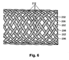
- Figure 6 illustrates a stent in which the entire stent body is covered with the adhesive
- only a portion of the stent may be covered with adhesive.
- a stent in accordance with the present invention is an ideal vector for delivery of a drug or other medical substance. Such delivery could be accomplished by incorporating the drug or other substance into any part of the stent (threads, axial filament or adhesive) or coating any part of the stent with a drug eluding coating.
- any part of the stent or entire stent can be made radiopaque by the addition a radiopaque filler such as a ceramic, metal, or metallic alloy powder.
- a stent in accordance with the present invention was manufactured with 24 braided threads of a diameter of 0.27 mm.
- the threads were made of a copolymer of 96% poly-L-lactic acid and 4% poly-D-lactic acid. This copolymer was mixed with 20% by weight of BaSO 4 filler to improve its radiopacity.
- Four elastomeric filaments of Tecoflex 80-A having a diameter of approximately 0.25 mm each were interwoven into the stent body at the time of braiding. The axial filaments were adhered to the stent by applying an adhesive of Tecoflex 80-A dissolved in methylene chloride.
Landscapes
- Health & Medical Sciences (AREA)
- Engineering & Computer Science (AREA)
- Biomedical Technology (AREA)
- Cardiology (AREA)
- Oral & Maxillofacial Surgery (AREA)
- Transplantation (AREA)
- Heart & Thoracic Surgery (AREA)
- Vascular Medicine (AREA)
- Life Sciences & Earth Sciences (AREA)
- Animal Behavior & Ethology (AREA)
- General Health & Medical Sciences (AREA)
- Public Health (AREA)
- Veterinary Medicine (AREA)
- Media Introduction/Drainage Providing Device (AREA)
Description
- The invention pertains to self-expanding stents and particularly to methods of attaching axial filaments to the stent body to increase its radial expansion force.
- self-expanding stents such as braided or knitted stents for surgical implantation in body lumens (tubular vessels) are known for repairing or strengthening the vessels. A stent essentially is a hollow tube that supplements the body vessel. With respect to the medical condition of stenosis, in which a body lumen tends to collapse or otherwise close, the stent supports the wall of the vessel to prevent it from collapsing or closing. A blood vessel that is narrowed due to the build up of intra-vascular plaque is one example of a stenosis. With respect to the medical condition of aneurism, in which a body lumen is weakened and cannot properly withstand the internal pressure within the vessel and bulges out or ruptures, the stent serves essentially the opposite function in that it substitutes for or supplements a weakened portion of the vessel. Stents are known for insertion in blood vessels, bile ducts, colons, trachea, bronchi, esophagi, urethra, ureters, etc.
- Many different types of stents are commercially available at this time. Most stents need to be radially constricted, i.e., reduced in diameter, so that they can be inserted into the body lumen. Once they are in situ, the stent can be radially expanded to the desired diameter. Stents are known that are fabricated from rigid, but deformable materials that, when bent by force, tend to retain the bent shape. Such stents may be inserted into the body lumen in an unstressed radially minimal shape while mounted over a deflated balloon. When the stent is in situ, the balloon is inflated in order to radially expand the stent, which will then retain the radially expanded shape after the balloon is deflated and removed.
- Another type of stent is termed a self-expanding stent. Self-expanding stents can be compressed radially, but will expand to their original shape once the radially constricting force is removed. Some types of self-expanding stent are formed from materials that are superelastic or have shape memory characteristics. Such stents are commonly made of Nitinol, a biocompatible alloy that, depending on its chemical composition and thermomechanical history, may be used either as a shape memory material or a superelastic material. The Ultraflex stent manufactured and sold by Boston Scientific Corporation is an example of a knitted Nitinol stent.
- Another type of self-expanding stent that reverts to its original shape because it undergoes only elastic deformation when radially compressed is exemplified in U.S. Patent No. 1,205,743, issued to Didcott. Didcott discloses a self-expanding, braided surgical dilator stent particularly adapted for esophageal dilation, but which can be adapted for use in other body vessels. This patent discloses a stent generally in accordance with the
stent 10 shown in Figure 1A hereof. It comprises a hollow tubular member, the wall of which is formed of a series of individual, flexible,thread elements flexible thread elements 12 have the same direction of winding and are displaced relative to each other about the cylindrical surface of the stent. They cross a second plurality ofhelical thread elements 14 which are also displaced relative to each other about the cylindrical surface of the stent, but having the opposite direction of winding. Accordingly, as shown in Figure 1A, thethreads 12 of the first subset cross thethreads 14 of the second subset atcrossing points 16. Figure 1A illustrates an embodiment in which the crossing threads are fully interlaced, however, the crossing threads may be interlaced at other intervals, e.g., every other crossing point or every third crossing point. - As the stent is axially stretched, i.e., as the
longitudinal ends - The desired radial expansion force for a given stent depends on the application. When used in blood vessels, stents are commonly used to treat stenoses. Accordingly, such applications require relatively high radial expansion forces. Other applications, such as esophageal applications, require much lower forces.
- U.S. Patent No. 4,655,771 issued to Wallsten discloses a stent of the Didcott design particularly adapted for transluminal implantation in blood vessels for treating stenosis and aneurisms.
- In some applications, such as the esophageal application particularly discussed in the aforementioned patent to Didcott, the stent is temporary. In other applications, such as the blood vessel application discussed in the aforementioned Wallsten patent, the stent is permanent. In permanent installations, the tissue of the body lumen within which the stent is placed tends to grow around the stent such that the stent essentially becomes incorporated with the tissue of the body vessel and thus becomes permanently affixed. However, in the weeks or months before this occurs, the stent is held in position by friction between the outer surface of the stent body and the inner surface of the vessel created by the radial expansion force of the stent. Thus, the resting diameter of the stent is selected to be slightly larger than the inner diameter of the vessel so that there is a constant force between the inner wall of the vessel and the outer wall of the stent.
- Bioabsorbable stents are also known in the prior art. Bioabsorbable stents are manufactured from materials that dissolve over an extended period of time when exposed to body fluids and are absorbed into the surrounding cells of the body.
- Various bioabsorbable materials that are suitable for fabricating stents are known in the prior art including polymers such as poly-L,D-lactic acid, poly-L-lactic acid, poly-D-lactic acid, polyglycolic acid, polylactic acid, polycaprolactone, polydioxanone, poly(lactic acid-ethylene oxide) copolymers, or combinations thereof. Vainionp at al., Prog Polym. Sci., vol. 14, pp. 697-716 (1989); United States Patent No. 4,700,704, United States Patent No. 4,653,497, United States Patent No. 4,649,921, United States Patent No. 4,599,945, United States Patent No. 4,532,928, United States Patent No. 4,605,730, United States Patent No. 4,441,496, and United States Patent No. 4,435,590, disclose various compounds from which bioabsorbable stents can be fabricated.
- Self-expanding braided stents rely on the spring force of the crossing threads that form the stent body to provide the radial expansion force. The magnitude of the radial expansion force is, therefore, a function of such factors as the number of threads, the size of the individual threads, the moduli of elasticity and rigidity of the thread material, and the initial crossing angle of the threads. US 5 758 562 discloses a braided stent with axial runners fixed to the stent to prevent unravelling. Self-expanding knitted stents rely on a separate set of factors, including size and number of threads employed, the flexibility of the individual threads, and the particular knit pattern.
- These characteristics of the stent, however, must be chosen based on factors in addition to the desired radial expansion force. For instance, the size of the threads is at least partially limited by the size of the lumen within which it will be employed. Further, characteristics of the material forming the stent body and thus the tensile strength and moduli of elasticity and rigidity of the material is limited to materials which can be safely placed in a human body.
- Stents made from bioabsorbable materials exhibit different properties than corresponding metallic stent designs. Examples of properties that must be controlled when using bioabsorbable materials include degradation rates, material creep, and material position memory. These factors also affect the radial expansion force of the stent.
- Accordingly, it is desirable to have some other or additional means by which to enhance the radial self expansion force of the stent.
- It is an object of the present invention to provide methods and designs to achieve optimum performance employing polymeric materials in stents and more preferably polymeric bioabsorbable materials.
- It is another object of the present invention to provide an improved method of attaching to a polymeric stent supplemental elastomeric filaments for increasing the radial expansion force of the stent.
- It is further object of the present invention to provide an improved bioabsorbable stent with enhanced radial self expansion force.
- It is yet a further object of the present invention to provide an improved bioabsorbable stent with attached supplemental elastomeric filaments for increasing the radial expansion force of the stent.
- The invention pertains to methods for attaching to a stent an axial elastomeric filament for enhancing radial expansion force of a self expanding stent, particularly a polymeric, braided, self expanding, stent. It also pertains to stents having attached axial filaments for enhancing the radial expansion force of the stent. In accordance with the invention, the axial filament or filaments are adhesively bonded to the stent body either over their entire length or at intervals. In one embodiment, adhesive is applied with a syringe or a glue gun over the length of the filament. The stent, including the filaments, is then heat treated to cause the glue to bond the filaments to the stent body. Alternately, the glue may be applied only at those points where the axial filament intersects with a thread forming the body of the stent. In another embodiment, the glue is applied to a free standing filament and the filament is subsequently incorporated in or laid on the stent body.
- In another embodiment, the entire stent with the axial filament is sprayed with adhesive. In yet a further embodiment of the invention, a portion or all of the stent, including the filaments, is dipped into an adhesive solution.
- In yet a further embodiment of the invention, a band of adhesive is applied to the stent body with a syringe or glue gun and the adhesive itself forms an axial filament.
-
- Figure 1A is a plan view of a braided, self expanding stent in accordance with the prior art in its rest position.
- Figure 1B is a plan view of the stent of Figure 1A shown in a radially constricted/axially elongated state.
- Figure 2 is a plan view of a braided self, expanding stent in accordance with a first embodiment of the present invention.
- Figure 3 is a plan view of a braided, self expanding stent in accordance with a second embodiment of the present invention.
- Figure 4 is a plan view of a braided, self expanding stent in accordance with a third embodiment of the present invention.
- Figure 5 is a plan view of a braided, self expanding stent in accordance with a fourth embodiment of the present invention.
- Figure 6 is a plan view of a braided, self expanding stent not in accordance with the present invention.
- As previously noted, the diameter of a self-expanding stent can be reduced and the length commensurately increased by applying either a radially restrictive force or a longitudinally lengthening force. When that force is removed, the stent tends to spring back towards its original diameter and length. Also as previously noted, the magnitude of the radially expansive force depends on many factors, including the material and particularly the rigidity of the threads, the thickness of the threads, the number of threads, and the crossing angle at rest of the threads. Generally, the greater the crossing angle at rest, the greater the radially expansive force. The magnitude of the expansive force is important for several reasons. For instance, the expansive force applied against the inner walls of the body vessel within which the stent is installed is the force that holds the stent in place until the tissue of the vessel can grow over and around the stent and thus permanently affix the stent within the vessel. Further, in many applications, the very purpose of the stent is to hold the vessel open and thus the proper magnitude of radially expansive force is critical. In some applications, such as implantation in blood vessels, the expansive force needs to be relatively large to hold the vessel open. In others, such as esophageal applications, the force must be considerably less.
- In many applications, it may be desirable to supplement the radially expansive force inherently provided by this type of stent design. For instance, the size of the vessel and/or the route through which the stent must be inserted may dictate that the threads be thin or of a certain number that is insufficient to provide the desired radially expansive force.
- U.S. Patent Application No. 09/626,638 filed October 4, 2000, entitled SELF-EXPANDING STENT WITH ENHANCED RADIAL EXPANSION published as WO 02/09617 on 7.2.2002, assigned to the same assignee as the present invention discloses several different mechanisms for enhancing the radial expansion force of a bioabsorbable, braided, self-expanding stent. One of the mechanisms disclosed therein for enhancing radial expansion force utilizes one or more axial filaments that are attached to the stent body.
- Figure 2 is a plan view of a
stent 200 in accordance with the aforementioned patent application and further illustrating a first embodiment of the present invention. Figure 2 illustrates a braided self-expandingstent 200. However, it should be understood that the methods and apparatus in accordance with the present invention also can be applied to any kind of self-expanding stent. Further, while the invention will be described herein with respect to particular embodiments wherein at least the threads forming the stent body are formed of a bioabsorbable material, it should be understood by persons of skill in these arts that the invention also can be applied in connection with non-bioabsorbable stents. The body of the stent of Figure 2 is constructed primarily in accordance with the prior art and is composed of a first set ofthreads 202 helically wound around thelongitudinal axis 204 of thestent 200 and a second plurality ofthreads 206 helically wound in the opposite direction around thelongitudinal axis 204 of the stent. The first and second sets ofthreads points 208 and have crossing angles at rest of α. The two sets of threads may or may not be braided with each other. The two sets of threads may or may not be joined at the crossing points 208. - The
threads - Incorporated into the stent are
axial filaments 210 that run along the body of the stent and enhance the radial expansion force of the stent. - The
axial filaments 210 are elastic i.e., they recover their shape after being stretched. The axial filaments tend to counteract any axially elongating force and/or apply an axially constrictive force to the stent body. Accordingly, since axial constriction and radial expansion go hand in hand, the axial filaments enhance the radial expansion force of the stent. - Alternately or additionally, the
axial filaments 210 can be fabricated of a material that shrinks in length when exposed to moisture or body temperature. The shrinkage of theaxial filaments 210 will apply a longitudinally constricting and, therefore, radially expanding, force on the stent. The elastic axial filaments may be attached to the stent body such that they are in a state of non expansion when the stent is at its rest diameter (i.e., the diameter when no axial or radial force is applied to the stent body). In this type of embodiment, the axial filaments would counteract radially constricting forces or axially elongating forces applied to the stent and thus tend to enhance the radial expansion force up to the point where the stent diameter reaches its rest position. However, the axial filaments would have no tendency to increase the diameter of the stent beyond its rest diameter. - In other embodiments, the axial filaments are attached to the stent body such that they are in an elongated state when the stent would otherwise be at its rest diameter. In this type of embodiment, the axial filaments, not only counteract radially constricting forces or axially elongating forces applied to the stent, but also enhance the radial expansion force beyond the point where the stent diameter reaches what would otherwise be its rest diameter. Accordingly, in any given application, the axial filaments will cause the stent to have a larger diameter than it would have otherwise.
- This last described embodiment can be produced either by holding the stent in an axially constricted/radially expanded position during affixation of the axial filaments, or by holding the axial filaments in an elongated state during affixation, or both.
- Usually, during insertion, the entire stent, including the axial filaments, are longitudinally stretched in order to reduce its diameter so that it can be inserted into a body lumen more easily. When the stent is released from the insertion apparatus, the stent, under its own force as well as the supplemental force applied by the axial filaments, provides radially expansive force against the walls of the vessel within which it is inserted.
- Suitable materials for the axial filaments are biostable or preferably bioabsorbable elastic polymers that are biocompatible. The biostable elastomers consist mainly of polyurethane and silicone elastomers. One of the first elastomeric fibers produced was elastane or spandex, a segmented polyurethane, that was later commercialized by DuPont under the trade name Lycra™. Spandex is also available from other manufacturers such as Globe Manufacturing Corp. Several other companies manufacture biostable polyurethane elastomers especially for medical applications and medical implants. Thermedics Inc., a division of Thermo Electron Corp., manufactures several grades of biostable polyurethane elastomers commercialized under the trade names Tecoflex™, Tecothane™, Carbothane™, Tecophilic™ and Tecoplast™. Elastomedic Pty Ltd. has a family of biostable polyurethane elastomers commercialized under the trade name Elast-Eon™. Cardiotech International, Inc. has a family of biostable polyurethane elastomers commercialized under the trade names Chronoflex™ and Chronothane™. Cardiotech International, Inc. also commercialized Chronoprene, a thermoplastic rubber elastomer that can be used to manufacture axial filaments in accordance with the present invention.
- The Polymer Technology Group Incorporated has a family of biostable polyurethane elastomers commercialized under the trade names Biospan®, Bionate®, Elasthane®, Carbosil®, and Pursil®. Some of these polyurethanes contain silicone as soft segments.
- Those skilled in the art are aware that polyurethanes are susceptible to hydrolitic chain scission and, therefore, the term biostable may actually indicate very slow degradation kinetics.
- Silicones are another family of suitable elastomers for the axial filaments. Nusil Technology manufactures several grades of medical silicone elastomers. Applied Silicone Corporation, a division of Rhodia, commercialized other suitable silicone elastomers under the trade name Silbione®.
- Preferably, however, the axial filaments are made out a bioabsorbable elastomer. Epsilon polycaprolactone, available, for instance, from Birmingham Polymers, Inc., is a suitable bioabsorbable elastomer. Polyactive, available from Isotis, is another suitable bioabsorbable elastomer.
- US Patent number 5,468,253, and 5,713,920, assigned to Ethicon Inc., describe a suitable bioabsorbable elastomer that is a copolymer of epsilon-caprolactone, trimethylene carbonate, glycolide and para-dioxanone. U.S. Patent number 5,113,624, also assigned to Ethicon, Inc., describes a suitable bioabsorbable elastomer that is a copolymer of lactide and p-dioxanone.
- Suitable medical grade biodegradable polyurethane have also been synthesized. For instance, "Structure-Property Relationships of Degradable Polyurethane Elastomers containing an Amino Acid-Based Chain Extender" by Skarja and Woodhouse, J. Of Applied Polymer Science, Vol.75, pp. 1522-1534 (2000), describes such biodegradable polyurethane elastomers.
- Tepha, Inc., a subsidiary of Metabolix, Inc., is developing various grades of PHA (polyhdroxyalkanoate), a biocompatible and bioabsorbable polymer. The properties of these polymers range from stiff for PHB (polyhydroxybutyrate) to rubbery elastomers such as PHO (polyhydroxyoctanoate).
- By incorporating bioabsorbable axial filaments into a bioabsorbable stent, the entire device can be made bioabsorbable. However, it is not necessary that the entire stent be bioabsorbable. Typically it is most important for a stent to have a particular radial expansion force for a brief period of time immediately after it is installed, before the tissue at the implantation site grows around the stent. Particularly, as a stent remains in place, the surrounding tissue will grow over it and incorporate the stent into the tissue. However, immediately after the stent is in installed, it is held in place essentially exclusively by the friction created by the radial expansion force of the stent body against the inner wall of the lumen. Therefore, it may be advantageous in many cases for the axial filaments to be bioabsorbable and the stent body to be non-bioabsorbable. In this manner, the enhanced radial expansion force is applied only for a limited period immediately after the stent is installed. Then, as the axial filaments degrade over time, the enhanced radial force also diminishes over time. In fact, even where the entire stent is bioabsorbable, including the main body and the axial filaments, it is possible to fabricate the axial filaments so that they degrade more quickly than the stent body, thus providing decreasing radial expansion force over time in a fully bioabsorbable stent.
- Alternately, the stent body can be bioabsorbable while the axial filaments are not. In such a case, the axial filaments will simply be incorporated into the tissue as the tissue grows around the stent. Accordingly, the axial filaments will not interfere with flow through the body lumen once the stent disintegrates.
- It has been found that attaching the axial filaments to the stent body by means of an adhesive is most effective. The adhesive used to attach the axial filaments to the stent body also should meet certain criteria. It should be medical-grade biocompatible. Most of the aforementioned axial filament materials can be dissolved in a solvent and used as the adhesive. If the stent, including the stent body and the axial filaments, are bioabsorbable, then it may also be preferable for the adhesive to be bioabsorbable.
- Once the axial filament is in place on the stent body, the solvent can be evaporated thus leaving behind the elastomer acting as an adhesive between the axial filaments and the body of the stent. Silicone also has been found to be a particularly suitable adhesive.
- Figure 2 illustrates a particular embodiment of the invention in which the axial filaments are attached to the stent body by adhesive 212. First, the axial filaments are brought into contact with the stent body. In the particular embodiment illustrated in Figure 2, the axial filaments are laid on top of the outer surface of the stent body. However, the filaments alternately could be laid on the inside surface of the body or interwoven into the
helically wound fibers - Alternately, the adhesive solution may be applied in lines over the stent body by syringe or glue gun and the axial filaments then laid on or in the adhesive bands. The stent, including the adhesive and axial filaments is then heat treated as previously discussed to form a structure similar to that shown in Figure 2. In this particular embodiment, the adhesive solution should be sufficiently viscous so that it can form bands on the stent body even though the adhesive bands must traverse open spaces between threads.
- Figure 3 illustrates an alternate embodiment which is similar to the embodiments discussed above in connection with Figure 2, except that the adhesive is applied only at the
points 214 where the axial filament overlie thethreads - In a preferred embodiment of the invention, the axial filament is interwoven with the braided structure of the stent body at the time of the braiding of the stent body. However, in alternate embodiments, the axial filaments could be laid on the inside surface, outside surface or both of the stent body after the stent body is braided. Even further, the axial filaments could be woven into the stent structure as shown in Figure 3, but at a time after the stent body itself has been fully formed.
- In another embodiment of the invention, the axial filaments can first be covered with the adhesive and then applied to the stent body. The adhesive-covered axial filaments can be applied on the outer surface of the stent body, the inner surface of the stent body, both surfaces and/or interwoven with the threads of the stent body. Then, the stent, including the axial filaments can be heat treated as discussed above in connection with Figures 2 and 3.
- In yet another embodiment of the invention illustrated in Figure 4, the
axial filaments 210 can be applied on the outer surface of the stent body (shown), the inner surface of the stent body and/or interwoven with the threads of the stent body and the entire stent sprayed with the adhesive solution. The stent is then heat treated as discussed above. As can be seen, in this embodiment, theentire stent 200 including the stent body and theaxial filaments 210 are coated with the adhesive 212. In another embodiment of the invention, the stent can be prepared exactly in the manner discussed above in connection with Figure 4 except that, instead of spraying the stent body with an adhesive solution, the stent body is dipped in an adhesive solution. - With particular respect to the last two embodiments discussed above, (in which all of the helical threads of the stent body as well as the axial filaments are coated with adhesive), the adhesive layer on the threads of the stent body will alter the stiffness of the stent. Particularly, it will increase the stiffness of the stent. Thus, inherently, it also will increase the resistance of the stent to changes in radial diameter or axial length. Accordingly, the adhesive itself helps enhance the radial self expansion force of the stent.
- In another embodiment illustrated in Figure 5, instead of axial filaments, axial bands of adhesive 215 are applied directly to the stent body. The quantity of adhesive (e.g., the thickness of the adhesive bands) is sufficient to enhance the radial expansion force of the stent in and of themselves, without the need for axial filaments. The axial bands of adhesive can be continuous or discontinuous.
- In another stent, not within the scope of the current claims, illustrated in Figure 6, the axial filaments and/or axial bands of adhesive are omitted and the stent is either sprayed with or dipped in an adhesive solution. The enhanced radial self expansion force then is provided solely by the adhesive coating on the
threads - Webs of adhesive form at the crossing points (or interstices) where two counter helically wound threads meet. The enhanced radial expansion force is provided particularly, but not necessarily solely, due to the formation of the webs of adhesive at the interstices of the counter helically wound threads forming the main body of the stent.
- While Figure 6 illustrates a stent in which the entire stent body is covered with the adhesive, in other embodiments, only a portion of the stent may be covered with adhesive. For instance, depending on the particular embodiment, it may be desirable to dip only one or both ends of the stent in the adhesive. For example, if both ends of the stent were dipped in the glue, but the middle was left uncovered, then the stent would be stiffer near the ends than in the middle, this stent would not however be within the scope of the claims.
- Those skilled in the art also will recognize that a stent in accordance with the present invention is an ideal vector for delivery of a drug or other medical substance. Such delivery could be accomplished by incorporating the drug or other substance into any part of the stent (threads, axial filament or adhesive) or coating any part of the stent with a drug eluding coating.
- Those of skill in the relevant arts also will recognize that any part of the stent or entire stent can be made radiopaque by the addition a radiopaque filler such as a ceramic, metal, or metallic alloy powder.
- A stent in accordance with the present invention was manufactured with 24 braided threads of a diameter of 0.27 mm. The threads were made of a copolymer of 96% poly-L-lactic acid and 4% poly-D-lactic acid. This copolymer was mixed with 20% by weight of BaSO4 filler to improve its radiopacity. Four elastomeric filaments of Tecoflex 80-A having a diameter of approximately 0.25 mm each were interwoven into the stent body at the time of braiding. The axial filaments were adhered to the stent by applying an adhesive of Tecoflex 80-A dissolved in methylene chloride.
- Having thus described a few particular embodiments of the invention, various alterations, modifications, and improvements will readily occur to those skilled in the art. Such alterations, modifications and improvements as are made obvious by this disclosure are intended to be part of this description though not expressly stated herein, and are intended to be within the scope of the invention. Accordingly, the foregoing description is by way of example only, and not limiting. The invention is limited only as defined in the following claims.
Claims (15)
- A method of fabricating a self-expanding stent (200) with enhanced radial expansion force, said method comprising the steps of:(1.) providing a stent body (202,206) in the shape of a tube;(2.) providing at least one filament (210) arranged axially to said stent (200), said filament. (210) being elastic;(3.) attaching said filament (210) to said stent body (202,206) characterised in that the filament is attached with an adhesive in a position such that said filament (210) exerts an axial compression force on said stent body (202,206) when said stent (200) is axially elongated.
- The method of claim 1 wherein said filament (210) is positioned such that said filament (210) exerts an axial compression force on said stent body (202,206) when said stent (200) is at a diameter that would otherwise be its rest diameter.
- The method of claim 1 wherein said stent body is comprised of at least one thread (202,206) and wherein step (3.) comprises:(3.1) placing said filament (210) axially on said stent body (202,206);(3.2) applying adhesive dissolved in a solvent to said filament (210); and(3.3) thereafter evaporating said solvent.
- The method of claim 3 wherein said stent body comprises a first set of threads (202) helically wound in a first direction and a second set of threads (206) helically wound in a second direction wherein said first set of threads (202) and said second set of threads (206) cross each other (208) and wherein step (3.2) comprises applying said adhesive only at points (214) where said axial filament (210) intersects with said threads (202,206) forming said stent body.
- The method of claim 3 wherein step (3.3) comprises heat treating said stents (200).
- The method of claim 3 wherein step (3.1) comprises placing said filament (210) on an inner surface of said stent body (202,206).
- The method of claim 4 wherein step (3.1) comprises interweaving said filament (210) with said threads (202,206) forming said stent body.
- The method of claim 1 wherein step (3.) comprises:(3.1) applying adhesive to said filament (210);(3.2) placing said filament (210) with said adhesive axially on said stent body (202,206); and(3.3) thereafter heat treating said stent (200).
- The method of claim 1 wherein step (3.) comprises(3.1) placing said filament (210) axially on said stent body (202,206)(3.2) spraying adhesive dissolved in a solvent on said stent (200); and(3.3) thereafter evaporating said solvent.
- The method of claim 1 wherein step (3.) comprises(3.1) placing said filament (210) axially on said stent body (202,206)(3.2) dipping said stent (200) in a solution of adhesive dissolved in solvent; and(3.3) thereafter evaporating said solvent.
- The method of claim 3 wherein said threads of said stent body (202,206) are formed of a bioabsorbable polymer, said axial filaments (210) are formed of a bioabsorbable polymer and said adhesive comprises a bioabsorbable polymer.
- A self-expanding stent (200) with enhanced radial expansion force comprising:a stent body (202,206) in the shape of a tube;characterized by at least one strip of adhesive (215) running axially along said stent body (202,206) and bonded to said stent body (202, 206).
- The stent of claim 12 wherein said adhesive (215) is an elastomeric polymer.
- The stent of claim 12 wherein, in the absence of an external force on said stent (200), said adhesive (215) holds said stent body (202,206) in a position in which it has a radial diameter greater than a resting radial diameter of said stent body (202,206).
- The stent of claim 14 wherein said adhesive (215) is formed of a bioabsorbable polymer and said stent body (202,206) is formed of a bioabsorbable polymer.
Applications Claiming Priority (3)
| Application Number | Priority Date | Filing Date | Title |
|---|---|---|---|
| US847919 | 2001-05-03 | ||
| US09/847,919 US6551352B2 (en) | 2001-05-03 | 2001-05-03 | Method for attaching axial filaments to a self expanding stent |
| PCT/US2002/007544 WO2002089706A1 (en) | 2001-05-03 | 2002-03-13 | Method for attaching axial filaments to a self expanding stent |
Publications (3)
| Publication Number | Publication Date |
|---|---|
| EP1389974A1 EP1389974A1 (en) | 2004-02-25 |
| EP1389974A4 EP1389974A4 (en) | 2004-04-07 |
| EP1389974B1 true EP1389974B1 (en) | 2006-11-08 |
Family
ID=25301825
Family Applications (1)
| Application Number | Title | Priority Date | Filing Date |
|---|---|---|---|
| EP02719207A Expired - Lifetime EP1389974B1 (en) | 2001-05-03 | 2002-03-13 | Method for attaching axial filaments to a self expanding stent |
Country Status (5)
| Country | Link |
|---|---|
| US (1) | US6551352B2 (en) |
| EP (1) | EP1389974B1 (en) |
| JP (1) | JP2004528115A (en) |
| DE (1) | DE60215931T2 (en) |
| WO (1) | WO2002089706A1 (en) |
Families Citing this family (77)
| Publication number | Priority date | Publication date | Assignee | Title |
|---|---|---|---|---|
| US6592617B2 (en) * | 1996-04-30 | 2003-07-15 | Boston Scientific Scimed, Inc. | Three-dimensional braided covered stent |
| ATE286687T1 (en) * | 1997-07-17 | 2005-01-15 | Schneider Europ Gmbh | STENT AND PRODUCTION METHOD THEREOF |
| US20040254635A1 (en) | 1998-03-30 | 2004-12-16 | Shanley John F. | Expandable medical device for delivery of beneficial agent |
| US9522217B2 (en) | 2000-03-15 | 2016-12-20 | Orbusneich Medical, Inc. | Medical device with coating for capturing genetically-altered cells and methods for using same |
| US8088060B2 (en) | 2000-03-15 | 2012-01-03 | Orbusneich Medical, Inc. | Progenitor endothelial cell capturing with a drug eluting implantable medical device |
| EP1582180B1 (en) | 2000-10-16 | 2008-02-27 | Conor Medsystems, Inc. | Expandable medical device for delivery of beneficial agent |
| AU2002230941A1 (en) * | 2000-10-31 | 2002-05-15 | Prodesco, Inc. | Supported lattice for cell cultivation |
| WO2002074198A2 (en) * | 2001-03-20 | 2002-09-26 | Gmp Cardiac Care, Inc | Rail stent |
| US20040249443A1 (en) * | 2001-08-20 | 2004-12-09 | Shanley John F. | Expandable medical device for treating cardiac arrhythmias |
| MXPA05001845A (en) * | 2002-08-15 | 2005-11-17 | Gmp Cardiac Care Inc | Stent-graft with rails. |
| WO2004045474A1 (en) * | 2002-11-15 | 2004-06-03 | Gmp Cardiac Care, Inc. | Rail stent |
| US7122058B2 (en) * | 2002-12-02 | 2006-10-17 | Gi Dynamics, Inc. | Anti-obesity devices |
| US7608114B2 (en) | 2002-12-02 | 2009-10-27 | Gi Dynamics, Inc. | Bariatric sleeve |
| US7998188B2 (en) | 2003-04-28 | 2011-08-16 | Kips Bay Medical, Inc. | Compliant blood vessel graft |
| US20050131520A1 (en) | 2003-04-28 | 2005-06-16 | Zilla Peter P. | Compliant blood vessel graft |
| WO2004096095A2 (en) | 2003-04-28 | 2004-11-11 | Medtronic, Inc. | Compliant venous graft |
| US7476256B2 (en) | 2003-12-09 | 2009-01-13 | Gi Dynamics, Inc. | Intestinal sleeve |
| US7854756B2 (en) | 2004-01-22 | 2010-12-21 | Boston Scientific Scimed, Inc. | Medical devices |
| US20060206200A1 (en) * | 2004-05-25 | 2006-09-14 | Chestnut Medical Technologies, Inc. | Flexible vascular occluding device |
| CA2758946C (en) | 2004-05-25 | 2014-10-21 | Tyco Healthcare Group Lp | Vascular stenting for aneurysms |
| US8617234B2 (en) | 2004-05-25 | 2013-12-31 | Covidien Lp | Flexible vascular occluding device |
| US8623067B2 (en) | 2004-05-25 | 2014-01-07 | Covidien Lp | Methods and apparatus for luminal stenting |
| AU2005247490B2 (en) | 2004-05-25 | 2011-05-19 | Covidien Lp | Flexible vascular occluding device |
| US7837726B2 (en) * | 2005-03-14 | 2010-11-23 | Abbott Laboratories | Visible endoprosthesis |
| WO2006104648A2 (en) * | 2005-03-24 | 2006-10-05 | Medtronic Vascular, Inc. | Hybrid biodegradable/non-biodegradable stent, delivery system and method of treating a vascular condition |
| DE102006040301A1 (en) * | 2005-12-06 | 2008-03-06 | Düring, Klaus, Dr. | Device for splinting a cavity, organ path and / or vessel |
| US8152833B2 (en) | 2006-02-22 | 2012-04-10 | Tyco Healthcare Group Lp | Embolic protection systems having radiopaque filter mesh |
| US20070203564A1 (en) * | 2006-02-28 | 2007-08-30 | Boston Scientific Scimed, Inc. | Biodegradable implants having accelerated biodegradation properties in vivo |
| CN102836023B (en) * | 2006-10-18 | 2015-12-02 | 印斯拜尔Md有限公司 | The support casing of braiding |
| US9622888B2 (en) | 2006-11-16 | 2017-04-18 | W. L. Gore & Associates, Inc. | Stent having flexibly connected adjacent stent elements |
| US8814930B2 (en) * | 2007-01-19 | 2014-08-26 | Elixir Medical Corporation | Biodegradable endoprosthesis and methods for their fabrication |
| DE102007012964A1 (en) * | 2007-03-06 | 2008-09-11 | Phenox Gmbh | Implant for influencing blood flow |
| US20080319528A1 (en) * | 2007-06-25 | 2008-12-25 | Abbott Laboratories | Modular endoprosthesis with flexible interconnectors between modules |
| US8317857B2 (en) * | 2008-01-10 | 2012-11-27 | Telesis Research, Llc | Biodegradable self-expanding prosthesis |
| US8303650B2 (en) | 2008-01-10 | 2012-11-06 | Telesis Research, Llc | Biodegradable self-expanding drug-eluting prosthesis |
| US8926688B2 (en) | 2008-01-11 | 2015-01-06 | W. L. Gore & Assoc. Inc. | Stent having adjacent elements connected by flexible webs |
| USD612499S1 (en) * | 2008-06-13 | 2010-03-23 | Ella-Cs, S.R.O. | Braided stent |
| DE102008033170A1 (en) * | 2008-07-15 | 2010-01-21 | Acandis Gmbh & Co. Kg | A braided mesh implant and method of making such an implant |
| DE102008038195A1 (en) * | 2008-08-19 | 2010-02-25 | Phenox Gmbh | Device for opening occluded blood vessels |
| DE102008048417A1 (en) * | 2008-09-23 | 2010-04-01 | Acandis Gmbh & Co. Kg | Medical device |
| US20100125326A1 (en) * | 2008-11-20 | 2010-05-20 | Medtronic Vascular, Inc. | Braided Stent With a Shortenable Tether |
| US8992601B2 (en) * | 2009-05-20 | 2015-03-31 | 480 Biomedical, Inc. | Medical implants |
| US9265633B2 (en) | 2009-05-20 | 2016-02-23 | 480 Biomedical, Inc. | Drug-eluting medical implants |
| US8137396B2 (en) * | 2009-05-20 | 2012-03-20 | 480 Biomedical, Inc | Medical implant |
| JP5827790B2 (en) * | 2010-04-28 | 2015-12-02 | 東レ・ダウコーニング株式会社 | Cosmetic and skin external preparation containing higher alcohol-modified silicone |
| US9636241B2 (en) * | 2012-03-30 | 2017-05-02 | Manli International Ltd | Coil bioabsorbable stents |
| US9114001B2 (en) | 2012-10-30 | 2015-08-25 | Covidien Lp | Systems for attaining a predetermined porosity of a vascular device |
| US9452070B2 (en) * | 2012-10-31 | 2016-09-27 | Covidien Lp | Methods and systems for increasing a density of a region of a vascular device |
| US9943427B2 (en) | 2012-11-06 | 2018-04-17 | Covidien Lp | Shaped occluding devices and methods of using the same |
| CN102988122B (en) * | 2012-11-13 | 2013-11-06 | 浦易(上海)生物技术有限公司 | Prosthetic system for treating nasosinusitis or allergic rhinitis |
| WO2014081914A2 (en) * | 2012-11-21 | 2014-05-30 | 480 Biomedical, Inc. | Stent with elastomeric elements |
| US9157174B2 (en) | 2013-02-05 | 2015-10-13 | Covidien Lp | Vascular device for aneurysm treatment and providing blood flow into a perforator vessel |
| US9585695B2 (en) | 2013-03-15 | 2017-03-07 | Woven Orthopedic Technologies, Llc | Surgical screw hole liner devices and related methods |
| US8956394B1 (en) | 2014-08-05 | 2015-02-17 | Woven Orthopedic Technologies, Llc | Woven retention devices, systems and methods |
| US9907593B2 (en) | 2014-08-05 | 2018-03-06 | Woven Orthopedic Technologies, Llc | Woven retention devices, systems and methods |
| US9730819B2 (en) | 2014-08-15 | 2017-08-15 | Elixir Medical Corporation | Biodegradable endoprostheses and methods of their fabrication |
| US9855156B2 (en) * | 2014-08-15 | 2018-01-02 | Elixir Medical Corporation | Biodegradable endoprostheses and methods of their fabrication |
| US9480588B2 (en) | 2014-08-15 | 2016-11-01 | Elixir Medical Corporation | Biodegradable endoprostheses and methods of their fabrication |
| US20160074071A1 (en) | 2014-09-16 | 2016-03-17 | Woven Orthopedic Technologies, Llc | Methods of using woven retention devices and systems |
| USD740427S1 (en) * | 2014-10-17 | 2015-10-06 | Woven Orthopedic Technologies, Llc | Orthopedic woven retention device |
| US10299948B2 (en) | 2014-11-26 | 2019-05-28 | W. L. Gore & Associates, Inc. | Balloon expandable endoprosthesis |
| US10555758B2 (en) | 2015-08-05 | 2020-02-11 | Woven Orthopedic Technologies, Llc | Tapping devices, systems and methods for use in bone tissue |
| ES2873887T3 (en) | 2016-05-16 | 2021-11-04 | Elixir Medical Corp | Stent release |
| US11622872B2 (en) | 2016-05-16 | 2023-04-11 | Elixir Medical Corporation | Uncaging stent |
| US10568752B2 (en) | 2016-05-25 | 2020-02-25 | W. L. Gore & Associates, Inc. | Controlled endoprosthesis balloon expansion |
| CN106400295B (en) * | 2016-08-31 | 2018-06-19 | 河南科技大学 | Three-dimensional woven tube and the three dimensional knitting machine and weaving for making the three-dimensional woven tube |
| US11395681B2 (en) | 2016-12-09 | 2022-07-26 | Woven Orthopedic Technologies, Llc | Retention devices, lattices and related systems and methods |
| US12599490B2 (en) | 2017-05-25 | 2026-04-14 | Elixir Medical Corporation | Uncaging stent |
| EP3677227B1 (en) | 2017-11-06 | 2022-04-27 | EA Pharma Co., Ltd. | Stent and medical device comprising same |
| JP7199950B2 (en) * | 2017-12-13 | 2023-01-06 | 日本毛織株式会社 | Biodegradable stent and medical device containing same |
| US11065136B2 (en) | 2018-02-08 | 2021-07-20 | Covidien Lp | Vascular expandable devices |
| US11065009B2 (en) | 2018-02-08 | 2021-07-20 | Covidien Lp | Vascular expandable devices |
| CN112312936A (en) * | 2018-03-12 | 2021-02-02 | 流体生物科技有限公司 | Bioabsorbable guide stent |
| EP3880120A4 (en) * | 2018-11-16 | 2022-08-24 | Microvention, Inc. | RADIOPAQUE VASCULAR PROSTHESIS |
| JP7545592B2 (en) | 2021-03-23 | 2024-09-04 | ボストン サイエンティフィック サイムド,インコーポレイテッド | ENDOPLASTY HAVING STRESS REDUCING FEATURES - Patent application |
| CN114939013B (en) * | 2022-05-31 | 2025-11-28 | 上海微创医疗器械(集团)有限公司 | Vascular reconstruction device, pushing device and medical system |
| JP2024066862A (en) * | 2022-11-02 | 2024-05-16 | 株式会社神戸製鋼所 | Stent Systems |
Family Cites Families (25)
| Publication number | Priority date | Publication date | Assignee | Title |
|---|---|---|---|---|
| SE445884B (en) | 1982-04-30 | 1986-07-28 | Medinvent Sa | DEVICE FOR IMPLANTATION OF A RODFORM PROTECTION |
| US4955899A (en) | 1989-05-26 | 1990-09-11 | Impra, Inc. | Longitudinally compliant vascular graft |
| US5383925A (en) | 1992-09-14 | 1995-01-24 | Meadox Medicals, Inc. | Three-dimensional braided soft tissue prosthesis |
| US5192308A (en) | 1991-04-19 | 1993-03-09 | E. I. Du Pont De Nemours And Company | Vascular prosthesis with an elastomer coating |
| CA2134090C (en) * | 1992-05-08 | 1997-03-25 | Liann M. Johnson | Esophageal stent and delivery tool |
| US5254113A (en) * | 1992-08-31 | 1993-10-19 | Wilk Peter J | Anastomosis method |
| US5382259A (en) | 1992-10-26 | 1995-01-17 | Target Therapeutics, Inc. | Vasoocclusion coil with attached tubular woven or braided fibrous covering |
| US5735892A (en) * | 1993-08-18 | 1998-04-07 | W. L. Gore & Associates, Inc. | Intraluminal stent graft |
| US6165210A (en) | 1994-04-01 | 2000-12-26 | Gore Enterprise Holdings, Inc. | Self-expandable helical intravascular stent and stent-graft |
| US6004388A (en) | 1994-09-16 | 1999-12-21 | Mitsubishi Pencil Kabushiki Kaisha | Non-aqueous ink for ball point pen, and ball point pen |
| US5637113A (en) | 1994-12-13 | 1997-06-10 | Advanced Cardiovascular Systems, Inc. | Polymer film for wrapping a stent structure |
| US5741332A (en) * | 1995-01-23 | 1998-04-21 | Meadox Medicals, Inc. | Three-dimensional braided soft tissue prosthesis |
| US5728131A (en) | 1995-06-12 | 1998-03-17 | Endotex Interventional Systems, Inc. | Coupling device and method of use |
| US5853418A (en) | 1995-06-30 | 1998-12-29 | Target Therapeutics, Inc. | Stretch resistant vaso-occlusive coils (II) |
| EP0754435B1 (en) | 1995-06-30 | 2000-11-08 | Target Therapeutics, Inc. | Stretch-resistant vaso-occlusive coils |
| US5582619A (en) | 1995-06-30 | 1996-12-10 | Target Therapeutics, Inc. | Stretch resistant vaso-occlusive coils |
| US6013084A (en) | 1995-06-30 | 2000-01-11 | Target Therapeutics, Inc. | Stretch resistant vaso-occlusive coils (II) |
| US5758562A (en) | 1995-10-11 | 1998-06-02 | Schneider (Usa) Inc. | Process for manufacturing braided composite prosthesis |
| US5628788A (en) | 1995-11-07 | 1997-05-13 | Corvita Corporation | Self-expanding endoluminal stent-graft |
| US6042605A (en) | 1995-12-14 | 2000-03-28 | Gore Enterprose Holdings, Inc. | Kink resistant stent-graft |
| US5718159A (en) * | 1996-04-30 | 1998-02-17 | Schneider (Usa) Inc. | Process for manufacturing three-dimensional braided covered stent |
| US5957974A (en) | 1997-01-23 | 1999-09-28 | Schneider (Usa) Inc | Stent graft with braided polymeric sleeve |
| US6340367B1 (en) * | 1997-08-01 | 2002-01-22 | Boston Scientific Scimed, Inc. | Radiopaque markers and methods of using the same |
| US6015432A (en) | 1998-02-25 | 2000-01-18 | Cordis Corporation | Wire reinforced vascular prosthesis |
| US6364904B1 (en) | 1999-07-02 | 2002-04-02 | Scimed Life Systems, Inc. | Helically formed stent/graft assembly |
-
2001
- 2001-05-03 US US09/847,919 patent/US6551352B2/en not_active Expired - Lifetime
-
2002
- 2002-03-13 EP EP02719207A patent/EP1389974B1/en not_active Expired - Lifetime
- 2002-03-13 DE DE60215931T patent/DE60215931T2/en not_active Expired - Fee Related
- 2002-03-13 JP JP2002586847A patent/JP2004528115A/en active Pending
- 2002-03-13 WO PCT/US2002/007544 patent/WO2002089706A1/en not_active Ceased
Also Published As
| Publication number | Publication date |
|---|---|
| US20020165597A1 (en) | 2002-11-07 |
| JP2004528115A (en) | 2004-09-16 |
| WO2002089706A1 (en) | 2002-11-14 |
| EP1389974A4 (en) | 2004-04-07 |
| US6551352B2 (en) | 2003-04-22 |
| DE60215931D1 (en) | 2006-12-21 |
| DE60215931T2 (en) | 2007-09-06 |
| EP1389974A1 (en) | 2004-02-25 |
Similar Documents
| Publication | Publication Date | Title |
|---|---|---|
| US6551352B2 (en) | Method for attaching axial filaments to a self expanding stent | |
| US6569191B1 (en) | Self-expanding stent with enhanced radial expansion and shape memory | |
| US20020165601A1 (en) | Bioabsorbable stent-graft and covered stent | |
| CA2383501C (en) | Balloon yielded delivery system and endovascular graft design for easy deployment | |
| EP3384878B1 (en) | A method of making a self-expanding implant | |
| EP2059198B1 (en) | Stents with connectors and stabilizing biodegradable elements | |
| US12036337B2 (en) | Implantable scaffolds for treatment of sinusitis | |
| US9326870B2 (en) | Biodegradable stent having non-biodegradable end portions and mechanisms for increased stent hoop strength | |
| EP3120877A1 (en) | Endoluminal device | |
| EP1993628A2 (en) | Biodegradable implants having accelerated biodegradation properties in vivo | |
| AU2018255421B2 (en) | Implantable scaffolds for treatment of sinusitis | |
| US11324862B2 (en) | Endoluminal device | |
| GB2475778A (en) | Implantable medical device comprising a self-expanding tubular structure | |
| EP3677227B1 (en) | Stent and medical device comprising same | |
| US20240400756A1 (en) | Aba tri-block copolymer and bioresorbable implants made therewith | |
| EP4720155A1 (en) | Aba tri-block copolymer and bioresorbable implants made therewith | |
| WO2022051533A2 (en) | Assessing the response to treatment of sinusitis | |
| WO2026070921A1 (en) | Indwelling object and method for producing porous structure |
Legal Events
| Date | Code | Title | Description |
|---|---|---|---|
| PUAI | Public reference made under article 153(3) epc to a published international application that has entered the european phase |
Free format text: ORIGINAL CODE: 0009012 |
|
| 17P | Request for examination filed |
Effective date: 20031125 |
|
| AK | Designated contracting states |
Kind code of ref document: A1 Designated state(s): AT BE CH CY DE DK ES FI FR GB GR IE IT LI LU MC NL PT SE TR |
|
| AX | Request for extension of the european patent |
Extension state: AL LT LV MK RO SI |
|
| A4 | Supplementary search report drawn up and despatched |
Effective date: 20040223 |
|
| 17Q | First examination report despatched |
Effective date: 20040623 |
|
| RAP1 | Party data changed (applicant data changed or rights of an application transferred) |
Owner name: LINVATEC BIOMATERIALS, INC. |
|
| RAP1 | Party data changed (applicant data changed or rights of an application transferred) |
Owner name: LINVATEC BIOMATERIALS, INC. |
|
| GRAP | Despatch of communication of intention to grant a patent |
Free format text: ORIGINAL CODE: EPIDOSNIGR1 |
|
| GRAS | Grant fee paid |
Free format text: ORIGINAL CODE: EPIDOSNIGR3 |
|
| GRAA | (expected) grant |
Free format text: ORIGINAL CODE: 0009210 |
|
| AK | Designated contracting states |
Kind code of ref document: B1 Designated state(s): DE FI FR GB IE |
|
| REG | Reference to a national code |
Ref country code: GB Ref legal event code: FG4D |
|
| REG | Reference to a national code |
Ref country code: IE Ref legal event code: FG4D |
|
| REF | Corresponds to: |
Ref document number: 60215931 Country of ref document: DE Date of ref document: 20061221 Kind code of ref document: P |
|
| PGFP | Annual fee paid to national office [announced via postgrant information from national office to epo] |
Ref country code: DE Payment date: 20070426 Year of fee payment: 6 |
|
| PGFP | Annual fee paid to national office [announced via postgrant information from national office to epo] |
Ref country code: FI Payment date: 20070427 Year of fee payment: 6 |
|
| ET | Fr: translation filed | ||
| PLBE | No opposition filed within time limit |
Free format text: ORIGINAL CODE: 0009261 |
|
| STAA | Information on the status of an ep patent application or granted ep patent |
Free format text: STATUS: NO OPPOSITION FILED WITHIN TIME LIMIT |
|
| 26N | No opposition filed |
Effective date: 20070809 |
|
| PGFP | Annual fee paid to national office [announced via postgrant information from national office to epo] |
Ref country code: GB Payment date: 20070425 Year of fee payment: 6 |
|
| PG25 | Lapsed in a contracting state [announced via postgrant information from national office to epo] |
Ref country code: IE Free format text: LAPSE BECAUSE OF NON-PAYMENT OF DUE FEES Effective date: 20070313 |
|
| PGFP | Annual fee paid to national office [announced via postgrant information from national office to epo] |
Ref country code: FR Payment date: 20070425 Year of fee payment: 6 |
|
| PG25 | Lapsed in a contracting state [announced via postgrant information from national office to epo] |
Ref country code: FI Free format text: LAPSE BECAUSE OF NON-PAYMENT OF DUE FEES Effective date: 20080313 |
|
| GBPC | Gb: european patent ceased through non-payment of renewal fee |
Effective date: 20080313 |
|
| REG | Reference to a national code |
Ref country code: FR Ref legal event code: ST Effective date: 20081125 |
|
| PG25 | Lapsed in a contracting state [announced via postgrant information from national office to epo] |
Ref country code: DE Free format text: LAPSE BECAUSE OF NON-PAYMENT OF DUE FEES Effective date: 20081001 |
|
| PG25 | Lapsed in a contracting state [announced via postgrant information from national office to epo] |
Ref country code: FR Free format text: LAPSE BECAUSE OF NON-PAYMENT OF DUE FEES Effective date: 20080331 |
|
| PG25 | Lapsed in a contracting state [announced via postgrant information from national office to epo] |
Ref country code: GB Free format text: LAPSE BECAUSE OF NON-PAYMENT OF DUE FEES Effective date: 20080313 |