EP1389816B2 - Installationsdose für elektrische Geräte - Google Patents
Installationsdose für elektrische Geräte Download PDFInfo
- Publication number
- EP1389816B2 EP1389816B2 EP03102347A EP03102347A EP1389816B2 EP 1389816 B2 EP1389816 B2 EP 1389816B2 EP 03102347 A EP03102347 A EP 03102347A EP 03102347 A EP03102347 A EP 03102347A EP 1389816 B2 EP1389816 B2 EP 1389816B2
- Authority
- EP
- European Patent Office
- Prior art keywords
- socket
- coupling means
- connectors
- installation box
- modules
- Prior art date
- Legal status (The legal status is an assumption and is not a legal conclusion. Google has not performed a legal analysis and makes no representation as to the accuracy of the status listed.)
- Expired - Lifetime
Links
Images


Classifications
-
- H—ELECTRICITY
- H01—ELECTRIC ELEMENTS
- H01R—ELECTRICALLY-CONDUCTIVE CONNECTIONS; STRUCTURAL ASSOCIATIONS OF A PLURALITY OF MUTUALLY-INSULATED ELECTRICAL CONNECTING ELEMENTS; COUPLING DEVICES; CURRENT COLLECTORS
- H01R9/00—Structural associations of a plurality of mutually-insulated electrical connecting elements, e.g. terminal strips or terminal blocks; Terminals or binding posts mounted upon a base or in a case; Bases therefor
- H01R9/22—Bases, e.g. strip, block, panel
- H01R9/24—Terminal blocks
- H01R9/2458—Electrical interconnections between terminal blocks
-
- H—ELECTRICITY
- H01—ELECTRIC ELEMENTS
- H01R—ELECTRICALLY-CONDUCTIVE CONNECTIONS; STRUCTURAL ASSOCIATIONS OF A PLURALITY OF MUTUALLY-INSULATED ELECTRICAL CONNECTING ELEMENTS; COUPLING DEVICES; CURRENT COLLECTORS
- H01R25/00—Coupling parts adapted for simultaneous co-operation with two or more identical counterparts, e.g. for distributing energy to two or more circuits
-
- H—ELECTRICITY
- H01—ELECTRIC ELEMENTS
- H01R—ELECTRICALLY-CONDUCTIVE CONNECTIONS; STRUCTURAL ASSOCIATIONS OF A PLURALITY OF MUTUALLY-INSULATED ELECTRICAL CONNECTING ELEMENTS; COUPLING DEVICES; CURRENT COLLECTORS
- H01R9/00—Structural associations of a plurality of mutually-insulated electrical connecting elements, e.g. terminal strips or terminal blocks; Terminals or binding posts mounted upon a base or in a case; Bases therefor
- H01R9/22—Bases, e.g. strip, block, panel
- H01R9/24—Terminal blocks
- H01R9/2408—Modular blocks
Definitions
- the invention relates to an installation box for electric appliances, said installation box consisting of a desired number of socket modules, each socket module comprising
- the electric appliances to be fitted in an installation box include particularly socket-outlets, but may also be switches, pushbuttons, and dimmers, used for the distribution and control of electricity in homes, offices and the like premises.
- the socket frame 10 comprises a bottom 1 and two opposite side walls 2. From the bottom extend attachment means 3a, 3b for attaching an actual socket-outlet appliance along with its cover 9.
- the side walls 2 have their upper edges provided with engagement brackets 4, 5 for fastening the installation box to the rims of a trunking or other socket frame installation opening.
- the engagement brackets include wedge-shaped projecting lugs 4, which connect with flexible tabs 6 in the side walls 2 and establish projecting response surfaces close to the free ends of the tabs 6.
- the side walls 2 have their upper edges provided with flanges 5, which lie at a small distance from the response surfaces of the lugs 4.
- the rims of a trunking or some other socket frame installation opening are provided with an engagement formation or an engagement rail, which is engageable between the flanges 5 and the lugs 4 as a preassembled socket-outlet or socket assembly is inserted in the installation opening.
- the socket frame 10 constitutes a socket module.
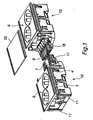
- two socket modules are assembled together electrically and mechanically by means of connectors 7 and 8, as subsequently described in more detail.
- the attachment means between the socket frame 10 and the socket-outlet fixture element 9 comprise, as shown in fig. 2 , semi-circular pins 3a and hook-like pillars 3b adjacent thereto, providing a snap-on connection with the engagement brackets of the socket-outlet 9 to be mounted on the socket frame 10.
- the attachment means may comprise screwfastening pillars, located adjacent to the side walls 2.
- Each socket module 10 has its first end provided with first coupling means 11 and its second end with second coupling means 12 for establishing a preformed locking with the first coupling means 11 of another socket module 10.
- the socket-outlet is infinitely extendable with the socket modules 10.
- the coupling means 11,12 are used in the present invention for securing the connectors 7 and 8 between boxes.
- the coupling means 11, 12 comprise profiled uprights at the ends of the side walls 2.
- the coupling means 11 at one end of the socket module 10 are constituted by T- or H-pillars 11 and the coupling means at the other end by C-pillars 12, which are dimensioned to fit around the T-top or the H-leg of the T- or H-pillars, respectively.
- C-pillars 12 are dimensioned to fit around the T-top or the H-leg of the T- or H-pillars, respectively.
- other types of profiled shapes can be relevant as well.
- the socket modules 10 have their ends near the bottom 1 provided with threshold-like end walls 13, 14, whose height is less than half of that of the side walls 2.
- the end walls 13, 14 are provided with snap-on locking means 15, 16 for locking the socket modules 10 flush with each other, in case the socket modules are coupled for a direct extension of each other. This snap-on connection must be readily disconnectable for the reuse and/or rearrangement of modules.
- Fig. 3 illustrates more clearly the design of bayonet connectors.
- the connectors include a 5-pole female connector element 7 and a 5-pole male connector element 8, as well as mountings 7a, 8a for attaching the connector elements 7, 8 thereto.
- the mountings 7a, 8a are in turn attachable to the ends of the socket frame 10.
- the mounting 7a is provided with coupling means 11' for establishing a preformed locking with the coupling means 12 present at one end of the socket frame 10.
- the mounting 8a is provided with coupling means 12' for establishing a preformed locking with the coupling means 11 present at the other end of the socket frame 10.
- the mountings 7a and 8a have their engagement brackets 20 engageable with attachment recesses 21 in the connectors 7 and 8.
- the connectors 7 and 8 have their side faces provided with clasps 17 and 18 to prevent a decoupling of the coupled connectors 7 and 8.
- the mountings 7a and 8a are provided with locking members 16 and 15 (not visible), matching the complementary locking members 15 and 16 of the socket modules 10 to enable locking of the mountings 7a, 8a and the connectors 7, 8 at a specified height within the socket module 10.
- Figs. 1 and 4 only illustrate the connectors 7 and 8 between socket-outlets. However, the opposite end of a socket-outlet with a connector 7 will receive a connector 8 and the opposite end of a socket-outlet with a connector 8 will receive a connector 7. These connectors enable connections either with an intermediate cable or with another socket-outlet.
- Fig. 4 visualizes that the assembled connectors 7, 8 are dimensioned to equal the length of a single socket module 10 and the connectors 7, 8 are concealable with a cover plate 22 ( figs. 1 and 5 ) pressable securely onto fastening members 19 rising from the mountings 7a, 8a (in the present case, a mortise and tenon joint).
- the connectors 7, 8 present at the opposite ends of each socket-outlet 9, 10 are linked with each other by way of cables.
- the 5-pole connectors 7 and 8 have three poles for three-phase linking, one pole for an 0-cable, and one pole for protective grounding.
- the invention is not limited to the above-described structural embodiment of a socket-outlet and connectors.
- the connectors 7, 8 can be made in one piece with their respective mountings 7a and 8a.
- the connectors 7 and 8 need not be dimensioned for a length equal to that of the socket module 10, but it can be shorter, e.g. a half of the socket module's 10 length, the cover plate 22 being respectively shorter.
- the releasable attachment of the connectors 7 and 8 facilitates the fabrication of components and enables a versatile application for the socket modules 10, such that the installation boxes can be optionally coupled either directly or by way of connectors as an extension of each other.
Landscapes
- Casings For Electric Apparatus (AREA)
- Connector Housings Or Holding Contact Members (AREA)
- Electrophonic Musical Instruments (AREA)
- Connection Or Junction Boxes (AREA)
Claims (4)
- Installationsdose für elektrische Geräte, wobei die Installationsdose aus einer gewünschten Anzahl von Steckdosen-Modulen (10) besteht, wobei jedes Steckdosen-Modul (10) aufweist:- einen Boden (1);- zwei gegenüberliegende Seitenwände (2);- Anbringungsmittel (3), die von dem Boden und/oder den Seitenwänden hervorstehen, zum Anbringen elektrischer Geräte;- Eingriffsklammern (4, 5) an den oberen Kanten der Seitenwände zum Befestigen der Installationsdose an den Rändern einer Hauptleitung bzw. eines Kabelkanals oder einer anderen Steckdosenrahmen-Installationsöffnung;- an einem ersten Ende vorhandene erste Kupplungsmittel (11) und an einem zweiten Ende des Steckdosen-Moduls (10) vorhandene zweite Kupplungsmittel (12), die mit den ersten Kopplungsmitteln (11) eines anderen Steckdosen-Moduls (10) eine vorgeformte Verriegelung bilden, wobei die Installationsdose mittels Steckdosen-Modulen (10) unendlich erweiterbar ist,dadurch gekennzeichnet, dass die Enden der Steckdosen-Module (10) mit Verbindungsvorrichtungen (7, 8) ausgestattet sind, die ein Buchsenelement (7) und ein Steckerelement (8) umfassen, welches mit dem Büchsenelement (7) kompatibel ist, das am Ende eines angrenzenden Steckdosen-Moduls (10) zur mechanischen und elektrischen Verbindung zwischen den Verbindungsvorrichtungen (7, 8) vorhanden ist, und dass einige der Verbindungsvorrichtungen (7, 8) mit Kopplungsmitteln (12') ausgestattet sind, um eine vorgeformte Verriegelung mit den ersten Kopplungsmitteln (11) zu bilden, und einige der Verbindungsvorrichtungen (7, 8) mit Kopplungsmitteln (11') ausgestattet sind, um eine vorgeformte Verriegelung mit den zweiten Kopplungsmitteln (12) zu bilden, wodurch die Steckdosen-Module (10) selektiv entweder direkt oder mittels der mechanischen und elektrischen Verbindung zwischen den Verbindungsvorrichtungen (7, 8) als eine Erweiterung jedes anderen gekoppelt werden können, und dass die Verbindungsvorrichtungen (7, 8) mit Befestigungsgliedern (19) zur Anbringung einer Abdeckplatte (22), welche den durch die miteinander verbundenen Verbindungsvorrichtungen (7, 8) eingenommenen Bereich verdickt, ausgestattet sind.
- Installationsdose nach Anspruch 1, dadurch gekennzeichnet, dass die Verbindungsvorrichtungen ein mehrpoliges Buchsen-Verbindung selement (7) und ein mehrpoliges Stift-Verbindungselement (8) sowie Montierelemente (7a, 8a), auf denen die Verbindungsvorrichtungen (7, 8) montierbar sind, enthalten, wobei die Montierelemente (7a, 8a) an den Enden des steckdosenmoduls (10) befestigbar sind.
- Installationsdose nach Anspruch 2, dadurch gekennzeichnet, dass einige (8a) der Montierelemente (7a, 8a) mit Kopplungsmitteln (12') ausgestattet sind, um eine vorgeformte Verriegelung mit den ersten Kopplungsmitteln (11) zu bilden, die an einem Ende des Steckdosenmoduls (10) vorhanden sind, und einige (7a) der Montierelemente (7a, 8a) mit Kopplungsmitteln (11') ausgestattet sind, um eine vorgeformte Verriegelung mit den zweiten Kopplungsmitteln (12) zu bilden, die an einem zweiten Ende des Steckdosenmoduls (10) vorhanden sind.
- Installationsdose nach Anspruch 2 oder 3, dadurch gekennzeichnet, dass die Befestigungsglieder (19) für die Abdeckplatte (22) in den Montierelementen (7a, 8a) enthalten sind.
Priority Applications (1)
| Application Number | Priority Date | Filing Date | Title |
|---|---|---|---|
| DE60308458T DE60308458T3 (de) | 2002-08-12 | 2003-07-30 | Installationsdose für elektrische Geräte |
Applications Claiming Priority (2)
| Application Number | Priority Date | Filing Date | Title |
|---|---|---|---|
| FI20021463A FI112727B (fi) | 2002-08-12 | 2002-08-12 | Asennusrasia sähkökojeita varten |
| FI20021463 | 2002-08-12 |
Publications (3)
| Publication Number | Publication Date |
|---|---|
| EP1389816A1 EP1389816A1 (de) | 2004-02-18 |
| EP1389816B1 EP1389816B1 (de) | 2006-09-20 |
| EP1389816B2 true EP1389816B2 (de) | 2012-11-14 |
Family
ID=8564425
Family Applications (1)
| Application Number | Title | Priority Date | Filing Date |
|---|---|---|---|
| EP03102347A Expired - Lifetime EP1389816B2 (de) | 2002-08-12 | 2003-07-30 | Installationsdose für elektrische Geräte |
Country Status (6)
| Country | Link |
|---|---|
| EP (1) | EP1389816B2 (de) |
| AT (1) | ATE340426T1 (de) |
| DE (1) | DE60308458T3 (de) |
| DK (1) | DK1389816T4 (de) |
| FI (1) | FI112727B (de) |
| NO (1) | NO333629B1 (de) |
Families Citing this family (3)
| Publication number | Priority date | Publication date | Assignee | Title |
|---|---|---|---|---|
| FR2928041B1 (fr) * | 2008-02-21 | 2013-01-11 | Rehau Sa | Prise d'alimentation electrique pour une goulotte ou analogue, utilisable individuellement ou en association. |
| ES2528225B1 (es) * | 2013-08-05 | 2015-10-08 | Schneider Electric España, S.A. | Sistema de conexión de elementos eléctricos |
| SE537815C2 (sv) | 2013-12-05 | 2015-10-20 | Moduel Ab | Elektriska moduler |
Family Cites Families (3)
| Publication number | Priority date | Publication date | Assignee | Title |
|---|---|---|---|---|
| AU579849B2 (en) * | 1984-05-22 | 1988-12-15 | H.P.M. Industries Pty Limited | Multi-socket power outlet |
| BE1013740A3 (nl) * | 2000-10-06 | 2002-07-02 | Camp Frans | Stopcontact. |
| FI109566B (fi) * | 2000-11-24 | 2002-08-30 | Ensto Busch Jaeger Oy | Asennusrasia sähkökojeita varten |
-
2002
- 2002-08-12 FI FI20021463A patent/FI112727B/fi not_active IP Right Cessation
-
2003
- 2003-07-30 EP EP03102347A patent/EP1389816B2/de not_active Expired - Lifetime
- 2003-07-30 AT AT03102347T patent/ATE340426T1/de not_active IP Right Cessation
- 2003-07-30 DE DE60308458T patent/DE60308458T3/de not_active Expired - Lifetime
- 2003-07-30 DK DK03102347.6T patent/DK1389816T4/da active
- 2003-08-01 NO NO20033445A patent/NO333629B1/no not_active IP Right Cessation
Also Published As
| Publication number | Publication date |
|---|---|
| DE60308458D1 (de) | 2006-11-02 |
| DE60308458T3 (de) | 2013-01-24 |
| NO20033445D0 (no) | 2003-08-01 |
| FI20021463A0 (fi) | 2002-08-12 |
| EP1389816B1 (de) | 2006-09-20 |
| FI112727B (fi) | 2003-12-31 |
| ATE340426T1 (de) | 2006-10-15 |
| DK1389816T4 (da) | 2012-12-17 |
| NO333629B1 (no) | 2013-07-29 |
| EP1389816A1 (de) | 2004-02-18 |
| DK1389816T3 (da) | 2007-01-29 |
| DE60308458T2 (de) | 2007-03-29 |
Similar Documents
| Publication | Publication Date | Title |
|---|---|---|
| US7189921B2 (en) | Housing arrangement with at least two junction boxes | |
| EP0434964B1 (de) | Bauelementensatz zum gleizeitigen elektrischen Verbinden einer Mehrzahl von modularen Selbstschaltern | |
| US20090142954A1 (en) | Electrical connecting apparatus for flat conductors | |
| MXPA00003898A (es) | Mensula para dispositivo. | |
| GB2214712A (en) | Housings for electrical consumer units | |
| EP1389816B1 (de) | Installationsdose für elektrische Geräte | |
| EP1209785A1 (de) | Befestigungsgehäuse für Verdrahtungszubehöre | |
| EP1933434B1 (de) | Kabelkanalsystem für Deckenaufhängung mit Haltebügeln | |
| EP2678903B1 (de) | Modulare elektrische verbindungseinheit | |
| US20070087603A1 (en) | Electrical system assembly with mounting bracket | |
| US6220901B1 (en) | Electric motor terminal board assembly | |
| EP1544972B1 (de) | Sammelschienenträger für Schaltschränke | |
| FI88447C (fi) | Elektriska kopplingar foer en kombination av elektriska kanaldosor | |
| FI115090B (fi) | Kaksoispistorasia | |
| EP1389811B1 (de) | Steckdosenanordnung | |
| AU677737B2 (en) | Multisocket module for socket outlets | |
| EP1109270A2 (de) | Steckdose für eine Beleuchtungseinrichtung | |
| GB2288697A (en) | Plug-in feed module for multi-socket outlet | |
| FI86928C (fi) | Taeckplatta foer en kombination av eldosor | |
| EP1306952B1 (de) | Elektrokanaldose | |
| IT201900005606A1 (it) | Frutto elettrico multipresa | |
| KR102879809B1 (ko) | 친환경 1/2 하프(Half) 인출형 유니트 기술을 적용한 모듈형 MCC | |
| EP1349250A1 (de) | Vorrichtung zur Haltung eines Mechanismus für Elektrische Installationen | |
| FI94992B (fi) | Virtakiskoadapteria varten tarkoitettu kytkentärasia | |
| GB2264816A (en) | Mounting electrical or other accessories |
Legal Events
| Date | Code | Title | Description |
|---|---|---|---|
| PUAI | Public reference made under article 153(3) epc to a published international application that has entered the european phase |
Free format text: ORIGINAL CODE: 0009012 |
|
| AK | Designated contracting states |
Kind code of ref document: A1 Designated state(s): AT BE BG CH CY CZ DE DK EE ES FI FR GB GR HU IE IT LI LU MC NL PT RO SE SI SK TR |
|
| AX | Request for extension of the european patent |
Extension state: AL LT LV MK |
|
| 17P | Request for examination filed |
Effective date: 20040818 |
|
| AKX | Designation fees paid |
Designated state(s): AT BE BG CH CY CZ DE DK EE ES FI FR GB GR HU IE IT LI LU MC NL PT RO SE SI SK TR |
|
| 17Q | First examination report despatched |
Effective date: 20050203 |
|
| GRAP | Despatch of communication of intention to grant a patent |
Free format text: ORIGINAL CODE: EPIDOSNIGR1 |
|
| GRAS | Grant fee paid |
Free format text: ORIGINAL CODE: EPIDOSNIGR3 |
|
| GRAA | (expected) grant |
Free format text: ORIGINAL CODE: 0009210 |
|
| AK | Designated contracting states |
Kind code of ref document: B1 Designated state(s): AT BE BG CH CY CZ DE DK EE ES FI FR GB GR HU IE IT LI LU MC NL PT RO SE SI SK TR |
|
| PG25 | Lapsed in a contracting state [announced via postgrant information from national office to epo] |
Ref country code: IT Free format text: LAPSE BECAUSE OF FAILURE TO SUBMIT A TRANSLATION OF THE DESCRIPTION OR TO PAY THE FEE WITHIN THE PRESCRIBED TIME-LIMIT;WARNING: LAPSES OF ITALIAN PATENTS WITH EFFECTIVE DATE BEFORE 2007 MAY HAVE OCCURRED AT ANY TIME BEFORE 2007. THE CORRECT EFFECTIVE DATE MAY BE DIFFERENT FROM THE ONE RECORDED. Effective date: 20060920 Ref country code: RO Free format text: LAPSE BECAUSE OF FAILURE TO SUBMIT A TRANSLATION OF THE DESCRIPTION OR TO PAY THE FEE WITHIN THE PRESCRIBED TIME-LIMIT Effective date: 20060920 Ref country code: CH Free format text: LAPSE BECAUSE OF FAILURE TO SUBMIT A TRANSLATION OF THE DESCRIPTION OR TO PAY THE FEE WITHIN THE PRESCRIBED TIME-LIMIT Effective date: 20060920 Ref country code: FI Free format text: LAPSE BECAUSE OF FAILURE TO SUBMIT A TRANSLATION OF THE DESCRIPTION OR TO PAY THE FEE WITHIN THE PRESCRIBED TIME-LIMIT Effective date: 20060920 Ref country code: CZ Free format text: LAPSE BECAUSE OF FAILURE TO SUBMIT A TRANSLATION OF THE DESCRIPTION OR TO PAY THE FEE WITHIN THE PRESCRIBED TIME-LIMIT Effective date: 20060920 Ref country code: LI Free format text: LAPSE BECAUSE OF FAILURE TO SUBMIT A TRANSLATION OF THE DESCRIPTION OR TO PAY THE FEE WITHIN THE PRESCRIBED TIME-LIMIT Effective date: 20060920 Ref country code: NL Free format text: LAPSE BECAUSE OF FAILURE TO SUBMIT A TRANSLATION OF THE DESCRIPTION OR TO PAY THE FEE WITHIN THE PRESCRIBED TIME-LIMIT Effective date: 20060920 Ref country code: SI Free format text: LAPSE BECAUSE OF FAILURE TO SUBMIT A TRANSLATION OF THE DESCRIPTION OR TO PAY THE FEE WITHIN THE PRESCRIBED TIME-LIMIT Effective date: 20060920 Ref country code: SK Free format text: LAPSE BECAUSE OF FAILURE TO SUBMIT A TRANSLATION OF THE DESCRIPTION OR TO PAY THE FEE WITHIN THE PRESCRIBED TIME-LIMIT Effective date: 20060920 Ref country code: BE Free format text: LAPSE BECAUSE OF FAILURE TO SUBMIT A TRANSLATION OF THE DESCRIPTION OR TO PAY THE FEE WITHIN THE PRESCRIBED TIME-LIMIT Effective date: 20060920 Ref country code: AT Free format text: LAPSE BECAUSE OF FAILURE TO SUBMIT A TRANSLATION OF THE DESCRIPTION OR TO PAY THE FEE WITHIN THE PRESCRIBED TIME-LIMIT Effective date: 20060920 |
|
| REG | Reference to a national code |
Ref country code: GB Ref legal event code: FG4D |
|
| REG | Reference to a national code |
Ref country code: CH Ref legal event code: EP |
|
| REG | Reference to a national code |
Ref country code: IE Ref legal event code: FG4D |
|
| REF | Corresponds to: |
Ref document number: 60308458 Country of ref document: DE Date of ref document: 20061102 Kind code of ref document: P |
|
| REG | Reference to a national code |
Ref country code: SE Ref legal event code: TRGR |
|
| REG | Reference to a national code |
Ref country code: EE Ref legal event code: FG4A Ref document number: E000707 Country of ref document: EE Effective date: 20060925 |
|
| PG25 | Lapsed in a contracting state [announced via postgrant information from national office to epo] |
Ref country code: BG Free format text: LAPSE BECAUSE OF FAILURE TO SUBMIT A TRANSLATION OF THE DESCRIPTION OR TO PAY THE FEE WITHIN THE PRESCRIBED TIME-LIMIT Effective date: 20061220 |
|
| PG25 | Lapsed in a contracting state [announced via postgrant information from national office to epo] |
Ref country code: ES Free format text: LAPSE BECAUSE OF FAILURE TO SUBMIT A TRANSLATION OF THE DESCRIPTION OR TO PAY THE FEE WITHIN THE PRESCRIBED TIME-LIMIT Effective date: 20061231 |
|
| REG | Reference to a national code |
Ref country code: DK Ref legal event code: T3 |
|
| NLV1 | Nl: lapsed or annulled due to failure to fulfill the requirements of art. 29p and 29m of the patents act | ||
| PG25 | Lapsed in a contracting state [announced via postgrant information from national office to epo] |
Ref country code: PT Free format text: LAPSE BECAUSE OF FAILURE TO SUBMIT A TRANSLATION OF THE DESCRIPTION OR TO PAY THE FEE WITHIN THE PRESCRIBED TIME-LIMIT Effective date: 20070312 |
|
| ET | Fr: translation filed | ||
| REG | Reference to a national code |
Ref country code: CH Ref legal event code: PL |
|
| PLBI | Opposition filed |
Free format text: ORIGINAL CODE: 0009260 |
|
| 26 | Opposition filed |
Opponent name: THORSMAN & CO AB Effective date: 20070619 |
|
| PLAX | Notice of opposition and request to file observation + time limit sent |
Free format text: ORIGINAL CODE: EPIDOSNOBS2 |
|
| PLBB | Reply of patent proprietor to notice(s) of opposition received |
Free format text: ORIGINAL CODE: EPIDOSNOBS3 |
|
| GBPC | Gb: european patent ceased through non-payment of renewal fee |
Effective date: 20070730 |
|
| PG25 | Lapsed in a contracting state [announced via postgrant information from national office to epo] |
Ref country code: GR Free format text: LAPSE BECAUSE OF FAILURE TO SUBMIT A TRANSLATION OF THE DESCRIPTION OR TO PAY THE FEE WITHIN THE PRESCRIBED TIME-LIMIT Effective date: 20061221 Ref country code: MC Free format text: LAPSE BECAUSE OF NON-PAYMENT OF DUE FEES Effective date: 20070731 |
|
| PG25 | Lapsed in a contracting state [announced via postgrant information from national office to epo] |
Ref country code: GB Free format text: LAPSE BECAUSE OF NON-PAYMENT OF DUE FEES Effective date: 20070730 |
|
| PG25 | Lapsed in a contracting state [announced via postgrant information from national office to epo] |
Ref country code: IE Free format text: LAPSE BECAUSE OF NON-PAYMENT OF DUE FEES Effective date: 20070730 |
|
| PG25 | Lapsed in a contracting state [announced via postgrant information from national office to epo] |
Ref country code: LU Free format text: LAPSE BECAUSE OF NON-PAYMENT OF DUE FEES Effective date: 20070730 Ref country code: CY Free format text: LAPSE BECAUSE OF FAILURE TO SUBMIT A TRANSLATION OF THE DESCRIPTION OR TO PAY THE FEE WITHIN THE PRESCRIBED TIME-LIMIT Effective date: 20060920 |
|
| PG25 | Lapsed in a contracting state [announced via postgrant information from national office to epo] |
Ref country code: HU Free format text: LAPSE BECAUSE OF FAILURE TO SUBMIT A TRANSLATION OF THE DESCRIPTION OR TO PAY THE FEE WITHIN THE PRESCRIBED TIME-LIMIT Effective date: 20070321 Ref country code: TR Free format text: LAPSE BECAUSE OF FAILURE TO SUBMIT A TRANSLATION OF THE DESCRIPTION OR TO PAY THE FEE WITHIN THE PRESCRIBED TIME-LIMIT Effective date: 20060920 |
|
| REG | Reference to a national code |
Ref country code: FR Ref legal event code: TP Ref country code: FR Ref legal event code: CD |
|
| REG | Reference to a national code |
Ref country code: EE Ref legal event code: GB1A Ref document number: E000707 Country of ref document: EE |
|
| RAP2 | Party data changed (patent owner data changed or rights of a patent transferred) |
Owner name: ABB OY |
|
| PLAY | Examination report in opposition despatched + time limit |
Free format text: ORIGINAL CODE: EPIDOSNORE2 |
|
| PLBC | Reply to examination report in opposition received |
Free format text: ORIGINAL CODE: EPIDOSNORE3 |
|
| PUAH | Patent maintained in amended form |
Free format text: ORIGINAL CODE: 0009272 |
|
| STAA | Information on the status of an ep patent application or granted ep patent |
Free format text: STATUS: PATENT MAINTAINED AS AMENDED |
|
| PGFP | Annual fee paid to national office [announced via postgrant information from national office to epo] |
Ref country code: EE Payment date: 20120713 Year of fee payment: 10 |
|
| 27A | Patent maintained in amended form |
Effective date: 20121114 |
|
| AK | Designated contracting states |
Kind code of ref document: B2 Designated state(s): AT BE BG CH CY CZ DE DK EE ES FI FR GB GR HU IE IT LI LU MC NL PT RO SE SI SK TR |
|
| REG | Reference to a national code |
Ref country code: DE Ref legal event code: R102 Ref document number: 60308458 Country of ref document: DE |
|
| REG | Reference to a national code |
Ref country code: DK Ref legal event code: T4 |
|
| REG | Reference to a national code |
Ref country code: SE Ref legal event code: RPEO |
|
| REG | Reference to a national code |
Ref country code: DE Ref legal event code: R102 Ref document number: 60308458 Country of ref document: DE Effective date: 20121114 |
|
| REG | Reference to a national code |
Ref country code: EE Ref legal event code: MM4A Ref document number: E000707 Country of ref document: EE Effective date: 20130731 |
|
| PG25 | Lapsed in a contracting state [announced via postgrant information from national office to epo] |
Ref country code: EE Free format text: LAPSE BECAUSE OF NON-PAYMENT OF DUE FEES Effective date: 20130731 |
|
| REG | Reference to a national code |
Ref country code: FR Ref legal event code: PLFP Year of fee payment: 13 |
|
| PGFP | Annual fee paid to national office [announced via postgrant information from national office to epo] |
Ref country code: FR Payment date: 20150626 Year of fee payment: 13 |
|
| PGFP | Annual fee paid to national office [announced via postgrant information from national office to epo] |
Ref country code: DE Payment date: 20150721 Year of fee payment: 13 Ref country code: DK Payment date: 20150721 Year of fee payment: 13 |
|
| PGFP | Annual fee paid to national office [announced via postgrant information from national office to epo] |
Ref country code: SE Payment date: 20150721 Year of fee payment: 13 |
|
| REG | Reference to a national code |
Ref country code: DE Ref legal event code: R119 Ref document number: 60308458 Country of ref document: DE |
|
| REG | Reference to a national code |
Ref country code: DK Ref legal event code: EBP Effective date: 20170131 |
|
| REG | Reference to a national code |
Ref country code: SE Ref legal event code: EUG |
|
| PG25 | Lapsed in a contracting state [announced via postgrant information from national office to epo] |
Ref country code: DE Free format text: LAPSE BECAUSE OF NON-PAYMENT OF DUE FEES Effective date: 20170201 Ref country code: FR Free format text: LAPSE BECAUSE OF NON-PAYMENT OF DUE FEES Effective date: 20160801 Ref country code: SE Free format text: LAPSE BECAUSE OF NON-PAYMENT OF DUE FEES Effective date: 20160731 |
|
| REG | Reference to a national code |
Ref country code: FR Ref legal event code: ST Effective date: 20170331 |
|
| PG25 | Lapsed in a contracting state [announced via postgrant information from national office to epo] |
Ref country code: DK Free format text: LAPSE BECAUSE OF NON-PAYMENT OF DUE FEES Effective date: 20160731 |