EP1389676A2 - Cooling equipment for a motor vehicle, in particular for an excavator - Google Patents
Cooling equipment for a motor vehicle, in particular for an excavator Download PDFInfo
- Publication number
- EP1389676A2 EP1389676A2 EP03102494A EP03102494A EP1389676A2 EP 1389676 A2 EP1389676 A2 EP 1389676A2 EP 03102494 A EP03102494 A EP 03102494A EP 03102494 A EP03102494 A EP 03102494A EP 1389676 A2 EP1389676 A2 EP 1389676A2
- Authority
- EP
- European Patent Office
- Prior art keywords
- radiator
- cooling equipment
- air
- air intake
- excavator
- Prior art date
- Legal status (The legal status is an assumption and is not a legal conclusion. Google has not performed a legal analysis and makes no representation as to the accuracy of the status listed.)
- Granted
Links
Images

Classifications
-
- F—MECHANICAL ENGINEERING; LIGHTING; HEATING; WEAPONS; BLASTING
- F01—MACHINES OR ENGINES IN GENERAL; ENGINE PLANTS IN GENERAL; STEAM ENGINES
- F01P—COOLING OF MACHINES OR ENGINES IN GENERAL; COOLING OF INTERNAL-COMBUSTION ENGINES
- F01P11/00—Component parts, details, or accessories not provided for in, or of interest apart from, groups F01P1/00 - F01P9/00
- F01P11/12—Filtering, cooling, or silencing cooling-air
-
- B—PERFORMING OPERATIONS; TRANSPORTING
- B60—VEHICLES IN GENERAL
- B60K—ARRANGEMENT OR MOUNTING OF PROPULSION UNITS OR OF TRANSMISSIONS IN VEHICLES; ARRANGEMENT OR MOUNTING OF PLURAL DIVERSE PRIME-MOVERS IN VEHICLES; AUXILIARY DRIVES FOR VEHICLES; INSTRUMENTATION OR DASHBOARDS FOR VEHICLES; ARRANGEMENTS IN CONNECTION WITH COOLING, AIR INTAKE, GAS EXHAUST OR FUEL SUPPLY OF PROPULSION UNITS IN VEHICLES
- B60K11/00—Arrangement in connection with cooling of propulsion units
- B60K11/02—Arrangement in connection with cooling of propulsion units with liquid cooling
- B60K11/04—Arrangement or mounting of radiators, radiator shutters, or radiator blinds
-
- F—MECHANICAL ENGINEERING; LIGHTING; HEATING; WEAPONS; BLASTING
- F01—MACHINES OR ENGINES IN GENERAL; ENGINE PLANTS IN GENERAL; STEAM ENGINES
- F01P—COOLING OF MACHINES OR ENGINES IN GENERAL; COOLING OF INTERNAL-COMBUSTION ENGINES
- F01P3/00—Liquid cooling
- F01P3/18—Arrangements or mounting of liquid-to-air heat-exchangers
Definitions
- the present invention relates to cooling equipment for an excavator.
- an excavator is provided, among other things, with cooling equipment designed for lowering the temperature of one or more coolant liquids set in circulation to and from the mechanical members that generate thermal energy.
- Such cooling equipment comprises, in general, an air intake, an air-delivery duct to one or more devices (such as radiators) for the cooling of fluids (coolant water, air, hydraulic oil, etc.), and a fan operable to send a flow of ambient air from the air intake towards the cooling devices, through the delivery duct, for providing the desired cooling on the fluids.
- devices such as radiators
- a fan operable to send a flow of ambient air from the air intake towards the cooling devices, through the delivery duct, for providing the desired cooling on the fluids.
- the major advantage of this solution is essentially the fact that the dimensions of the radiator are not linked to other dimensional characteristics of the excavator (such as the width thereof in a direction transverse to the direction of movement), so that the manufacturer can decide, with a certain degree of freedom, the overall dimensions of the excavator itself.
- the above configuration results in a lower noise level of the cooling system as observed in the cab of the vehicle, since the noise is emitted in a lateral direction, away from the cab.
- the air intakes are set on the front part of the vehicle bodywork, oriented in the direction of normal travel. Also in this case the radiator is set facing the air intakes.
- This second solution has the evident advantage that, in the conditions in which the excavator requires maximum dissipation of thermal energy, i.e., when the excavator is moving, this dissipation is facilitated by the motion of the vehicle itself.
- the radiator is located very close to the cab in which the driver sits, and moreover it receives the flow of air hit-on, which further increases the noise level. Furthermore, since both the air intakes and the radiator are located alongside the arm of the excavator, when the latter is in working conditions, there is consequently an increase in the deposit of dust on the outer surface of the radiator. This results in a layer of dust which considerably reduces heat exchange between the forced flow of air and the liquid passing through the radiator.
- the purpose of the present invention is therefore to provide cooling equipment for motor vehicles, in particular for excavators, that are exempt from the drawbacks described above.
- cooling equipment is provided for motor vehicles according to the characteristics claimed in claim 1.
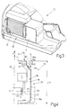
- the reference number 10 designates, as a whole, a motor vehicle (in particular an excavator), on which the cooling equipment 20 that forms the subject of the present invention is mounted.
- the excavator 10 presents an axis of longitudinal symmetry (a) ( Figure 4), which identifies two preferential directions of movement (forward and backward movement), represented schematically in Figure 4 by a double-headed arrow F.
- the excavator 10 comprises, in a known manner, a bodywork 11 (Figure 1) , comprising a front hydraulic arm 12 and a cab 13 designed to accommodate an operator (not illustrated).
- the bodywork 11 is mounted on a chassis (not illustrated), to which there are associated two axles (not illustrated), each comprising a corresponding pair of wheels 14 (only one wheel 14 is visible in Figure 1) .
- the cooling equipment 20 is located in a portion 11a of the bodywork 11, which is positioned, in the present case, to the right of the operator, who is seated, as has been said, in the cab 13.
- the portion 11a of the bodywork 11 in turn comprises air intake openings 15a, 15b provided on the front part of the portion 11a.
- the part of the equipment 20 housed inside the portion 11a of the bodywork 11 comprises the aforementioned openings 15a, 15b (the air flows being in the directions indicated by the arrows A1 and A2) connected, in fluid-dynamic manner, to a radiator 17 by means of an air-delivery duct 18.
- a deflector G is provided for guiding the air coming from the opening 15a (arrow A1) .
- the radiator 17 is provided, in a conventional way, with a suction fan V for taking in the ambient air, said fan V being set in rotation about an axis X ( Figure 4) by the engine M of the excavator 10 in a known manner.
- the radiator 17 is connected hydraulically, in a usual manner, by means of tubes (not illustrated) for conveying the coolant liquid to the parts of the excavator 10 that need to be cooled.
- the openings 15a, 15b are located in a position that is substantially perpendicular to the respective air flows defined by the arrows A1, A2 when the excavator 10 moves forward according to one of the two directions identified by the arrow F.
- the air-delivery duct 18, in particular, has a first stretch 18a, of which a longitudinal axis (b) is substantially parallel to the aforementioned axis of symmetry (a) of the excavator 10.
- a second stretch 18b of the duct 18 is set transverse to the radiator 17 and has an axis of longitudinal symmetry (c) which is substantially transverse with respect to the axis (a).
- the first stretch 18a and the second stretch 18b are connected physically to one another by a third stretch 18c, which substantially follows the outline of the portion 11a of the bodywork 11.
- the duct 18, according to a preferred solution uses the portion 11a of the bodywork 11 as an air guiding wall.
- the cooling equipment 20 has at least one air intake 15a, 15b positioned in a manner so that it is substantially perpendicular to the respective air flows, defined by the arrows A1, A2, whereby air flow is forced there through as a result of the forward movement of the excavator 10, whilst the radiator 17 is positioned in a substantially tangential manner with respect to the air flows defined by the arrows A1, A2.
- a fuel tank T the outer wall of which forms a portion of the delivery duct 18.
- a battery B is set facing the opening 15a and is impinged upon directly by the flow of air defined by the arrow A1.
- the battery housing is part of the first stretch 18a.
- the air intake 15a is situated on a front box-shaped element 11b (containing the aforementioned battery housing), which forms an integral part of the portion 11a of the bodywork 11.
- This front element 11b has the function of further silencing the entry of the air from the opening 15a.
- the radiator 17 is covered by a pivotable side bonnet panel 19, which enables easy access to the radiator 17 and associated elements, without having to gain access to these elements by passing through the openings 15a, 15b.
- the removable side bonnet panel 19 furthermore forms a side wall of the air-delivery duct 18, more in particular, at the portion 18c.
- the panel 19 could have air-entry openings, it is preferred not to in order to further reduce noise transmission towards the environment. Moreover, air entering through openings in the panel 19 would disturb the laminar flow of air through the duct 18.
- the dimensions of the radiator 17 are imposed not by the transverse dimension TR of the bodywork 11, but by the longitudinal dimension LN thereof. This represents a considerable advantage.
- the manufacturer has, instead, a certain degree of freedom in the choice of the overall longitudinal dimensions LN.
- a radiator 17 which is larger and designed such as to dissipate better and faster considerable amounts of heat produced by the excavator 10, above all in conditions that are more unfavourable from this point of view, i.e., in conditions of movement of the vehicle on wheels.
- radiator 17 is represented in the attached drawings as a single bloc element, it will be appreciated that in common practice a series of radiators (not illustrated) usually is provided for cooling the engine, for cooling the oil of the hydraulic system, for air conditioning, etc.
- the portion of the radiator 17 which is favoured and thus receives the largest amount of coolant air is the one which is located in the part thereof closest to the openings 15a and 15b. Consequently, the supplementary radiators (not illustrated) advantageously may be positioned preferably at the portion of the radiator 17 closest to the openings 15a and 15b.
Landscapes
- Engineering & Computer Science (AREA)
- Chemical & Material Sciences (AREA)
- Combustion & Propulsion (AREA)
- Mechanical Engineering (AREA)
- General Engineering & Computer Science (AREA)
- Transportation (AREA)
- Component Parts Of Construction Machinery (AREA)
- Cooling, Air Intake And Gas Exhaust, And Fuel Tank Arrangements In Propulsion Units (AREA)
- Motor Or Generator Cooling System (AREA)
- Transition And Organic Metals Composition Catalysts For Addition Polymerization (AREA)
Abstract
Description
Claims (10)
- Cooling equipment (20) for a motor vehicle (10), in particular for an excavator (10), said motor vehicle (10) having a longitudinal axis of symmetry (a) identifying two directions (F) of preferential movement; said equipment (20) comprising at least one air intake (15a, 15b), a duct (18) for delivery of the air to a radiator (17) for cooling of coolant liquids, and a fan (V) operable to send a flow of incoming air from said at least one air intake (15a, 15b) to said radiator (17), through said delivery duct (18), for providing the desired cooling of the coolant liquid; and
characterized in that said at least one air intake (15a, 15b) is positioned in a way substantially perpendicular to a flow (A1, A2) of air drawn in during the forward movement (F) of said excavator (10), and in that said radiator (17) is positioned in a manner substantially tangential to said flow (A1, A2) of air. - Cooling equipment (20) according to claim 1,
characterized in that said delivery duct (18) extends substantially in the longitudinal direction of the vehicle. - Cooling equipment (20) according to claim 2,
characterized in that said at least one air intake (15a, 15b) is positioned at a front portion of the vehicle bodywork (11) whereas the radiator is located at a rear portion thereof. - Cooling equipment (20) according to claim 3,
characterized in that an outer, lateral side of said delivery duct (18) is formed by a side bonnet panel (19) of the vehicle bodywork (11). - Cooling equipment (20) according to claim 4,
characterized in that at least part of said side bonnet panel (19) is pivotable to an open position for exposing the radiator (17). - Cooling equipment (20) according to any of the preceding claims, characterized in that said delivery duct (18) comprises :a first duct portion (18a) contiguous to said at least one air intake (15a, 15b) and having a longitudinal axis (b) which is substantially parallel to said axis (a); anda second duct portion (18b) contiguous to said radiator (17) and having a longitudinal axis (c) which is substantially transverse to said axis (a).
- Cooling equipment (20) according to any of the preceding claims, characterized in that said at least one air intake (15a, 15b) is located on a forwardly extending box-shaped element (11b), which forms an integral part of the bodywork (11) of the motor vehicle (10).
- Cooling equipment (20) according to claim 7,
characterized in that said box-shaped element (11b) serves as a battery housing for the motor vehicle (10). - Cooling equipment (20) according to any of the preceding claims, characterized in that a fuel tank (T) is housed alongside said radiator (17), an outer wall of said fuel tank (T) delimiting a part of said delivery duct (18).
- Cooling equipment (20) according to any of the preceding claims, characterized in that a further air intake (15b) is provided in said delivery duct (18) downstream of said at least one air intake (15a); said further air intake (15b) being shielded from the air (A1) coming from said at least one air intake (15a) by a deflector (G) .
Applications Claiming Priority (2)
| Application Number | Priority Date | Filing Date | Title |
|---|---|---|---|
| ITTO20020727 | 2002-08-14 | ||
| IT000727A ITTO20020727A1 (en) | 2002-08-14 | 2002-08-14 | COOLING EQUIPMENT FOR A VEHICLE, IN PARTICULAR FOR AN EXCAVATOR. |
Publications (3)
| Publication Number | Publication Date |
|---|---|
| EP1389676A2 true EP1389676A2 (en) | 2004-02-18 |
| EP1389676A3 EP1389676A3 (en) | 2005-05-04 |
| EP1389676B1 EP1389676B1 (en) | 2011-08-10 |
Family
ID=11459579
Family Applications (1)
| Application Number | Title | Priority Date | Filing Date |
|---|---|---|---|
| EP03102494A Expired - Lifetime EP1389676B1 (en) | 2002-08-14 | 2003-08-11 | Cooling equipment for a motor vehicle, in particular for an excavator |
Country Status (4)
| Country | Link |
|---|---|
| US (1) | US7182164B2 (en) |
| EP (1) | EP1389676B1 (en) |
| AT (1) | ATE519932T1 (en) |
| IT (1) | ITTO20020727A1 (en) |
Families Citing this family (8)
| Publication number | Priority date | Publication date | Assignee | Title |
|---|---|---|---|---|
| US7451843B2 (en) * | 2003-06-16 | 2008-11-18 | Kobelco Construction Machinery Co., Ltd. | Construction machine |
| KR101176513B1 (en) * | 2005-07-05 | 2012-08-23 | 얀마 가부시키가이샤 | Construction machine |
| JP4667141B2 (en) * | 2005-07-05 | 2011-04-06 | ヤンマー株式会社 | Swivel work vehicle |
| US8100210B2 (en) * | 2006-02-07 | 2012-01-24 | Takeuchi Mfg. Co., Ltd | Electrically driven industrial vehicle |
| US8978802B2 (en) * | 2012-08-15 | 2015-03-17 | Cnh Industrial America Llc | Air intake configuration for an agricultural harvesting machine |
| JP5949730B2 (en) * | 2013-11-07 | 2016-07-13 | コベルコ建機株式会社 | Electrical equipment arrangement structure for construction machinery |
| JP6229694B2 (en) * | 2015-06-08 | 2017-11-15 | コベルコ建機株式会社 | Construction machine with engine |
| CN106976392B (en) * | 2017-05-12 | 2023-07-28 | 合肥阳光电动力科技有限公司 | Radiating assembly and air duct structure of electric automobile |
Family Cites Families (15)
| Publication number | Priority date | Publication date | Assignee | Title |
|---|---|---|---|---|
| US3788418A (en) * | 1972-04-06 | 1974-01-29 | Caterpillar Tractor Co | System for cooling an hydraulic excavator |
| EP0727529B1 (en) * | 1995-02-17 | 1999-07-14 | Kubota Corporation | Backhoe having an engine hood with a driver's seat mounted thereon |
| JPH08268088A (en) * | 1995-03-31 | 1996-10-15 | Hitachi Constr Mach Co Ltd | Construction machinery cooling structure |
| JP3622316B2 (en) * | 1996-01-24 | 2005-02-23 | コベルコ建機株式会社 | Construction machine cooling system |
| JPH1089068A (en) * | 1996-09-20 | 1998-04-07 | Kubota Corp | Radiator intake structure of agricultural work vehicle |
| EP0947706B1 (en) * | 1997-09-19 | 2006-11-22 | Hitachi Construction Machinery Co., Ltd. | Cooling apparatus for construction machinery and construction machinery |
| US6032620A (en) * | 1997-10-31 | 2000-03-07 | Kabushiki Kaisha Kobe Seiko Sho | Air intake structure in a construction machine |
| KR100407491B1 (en) * | 1998-06-17 | 2003-11-28 | 히다치 겡키 가부시키 가이샤 | Fan device and shroud |
| JP3399416B2 (en) * | 1999-10-07 | 2003-04-21 | コベルコ建機株式会社 | Construction machine cooling structure |
| JP4450298B2 (en) * | 2000-01-12 | 2010-04-14 | 株式会社小松製作所 | Engine cooling air passage for construction machinery |
| US6431299B1 (en) * | 2000-04-05 | 2002-08-13 | Clark Equipment Company | Cooling air ducting for excavator |
| JP2001348909A (en) * | 2000-06-02 | 2001-12-21 | Shin Caterpillar Mitsubishi Ltd | Construction machinery |
| CN1201055C (en) * | 2000-12-01 | 2005-05-11 | 日立建机株式会社 | Construction machinery |
| JP3839280B2 (en) * | 2001-06-27 | 2006-11-01 | 新キャタピラー三菱株式会社 | Construction machine cooling package cover structure |
| JP3952972B2 (en) * | 2003-03-07 | 2007-08-01 | コベルコ建機株式会社 | Construction machine cooling system |
-
2002
- 2002-08-14 IT IT000727A patent/ITTO20020727A1/en unknown
-
2003
- 2003-08-05 US US10/634,939 patent/US7182164B2/en not_active Expired - Lifetime
- 2003-08-11 EP EP03102494A patent/EP1389676B1/en not_active Expired - Lifetime
- 2003-08-11 AT AT03102494T patent/ATE519932T1/en not_active IP Right Cessation
Also Published As
| Publication number | Publication date |
|---|---|
| ITTO20020727A1 (en) | 2004-02-15 |
| ATE519932T1 (en) | 2011-08-15 |
| US20040063396A1 (en) | 2004-04-01 |
| EP1389676A3 (en) | 2005-05-04 |
| US7182164B2 (en) | 2007-02-27 |
| ITTO20020727A0 (en) | 2002-08-14 |
| EP1389676B1 (en) | 2011-08-10 |
Similar Documents
| Publication | Publication Date | Title |
|---|---|---|
| US8875823B2 (en) | Multi-functional cooling system | |
| CA1073007A (en) | Front engine tractor having transverse midship mounted heat exchanger | |
| US6435264B1 (en) | Cooling system for working vehicle | |
| US8403089B2 (en) | Use of fan shroud to ventilate engine compartment | |
| US8695722B2 (en) | Bulldozer with improved visibility | |
| US20020053480A1 (en) | Mounting arrangement for a radiator assembly of a work machine | |
| WO2017068745A1 (en) | Working vehicle | |
| EP1389676B1 (en) | Cooling equipment for a motor vehicle, in particular for an excavator | |
| JP2001199251A (en) | Drive unit cooling structure for work vehicles | |
| JP6552320B2 (en) | Tractor | |
| US4917201A (en) | Motor vehicle | |
| JP7423560B2 (en) | Work vehicle cooling system and work vehicle | |
| JP7265504B2 (en) | work machine | |
| JPS63270228A (en) | Cooling and ventilation structure for work vehicles | |
| JPH11254976A (en) | Noise reducing device for construction machine and cover and exhaust part used for this device | |
| JP7058592B2 (en) | Work vehicle | |
| JP7781729B2 (en) | Work vehicle | |
| JP6530999B2 (en) | Tractor | |
| JP3623918B2 (en) | Cooling air flow device for traveling vehicle | |
| JP4208180B2 (en) | Engine heat transfer cutoff structure to cab in hydraulic excavator | |
| JP3386958B2 (en) | Work machine air cleaner air guide device | |
| TW202136098A (en) | Work vehicle hose routing | |
| JP2025116594A (en) | Work equipment | |
| WO2021075550A1 (en) | Wind guide mechanism and front structure for vehicle comprising wind guide mechanism | |
| JPH0346647B2 (en) |
Legal Events
| Date | Code | Title | Description |
|---|---|---|---|
| PUAI | Public reference made under article 153(3) epc to a published international application that has entered the european phase |
Free format text: ORIGINAL CODE: 0009012 |
|
| AK | Designated contracting states |
Kind code of ref document: A2 Designated state(s): AT BE BG CH CY CZ DE DK EE ES FI FR GB GR HU IE IT LI LU MC NL PT RO SE SI SK TR |
|
| AX | Request for extension of the european patent |
Extension state: AL LT LV MK |
|
| PUAL | Search report despatched |
Free format text: ORIGINAL CODE: 0009013 |
|
| AK | Designated contracting states |
Kind code of ref document: A3 Designated state(s): AT BE BG CH CY CZ DE DK EE ES FI FR GB GR HU IE IT LI LU MC NL PT RO SE SI SK TR |
|
| AX | Request for extension of the european patent |
Extension state: AL LT LV MK |
|
| 17P | Request for examination filed |
Effective date: 20051028 |
|
| AKX | Designation fees paid |
Designated state(s): AT BE BG CH CY CZ DE DK EE ES FI FR GB GR HU IE IT LI LU MC NL PT RO SE SI SK TR |
|
| 17Q | First examination report despatched |
Effective date: 20100224 |
|
| GRAP | Despatch of communication of intention to grant a patent |
Free format text: ORIGINAL CODE: EPIDOSNIGR1 |
|
| GRAS | Grant fee paid |
Free format text: ORIGINAL CODE: EPIDOSNIGR3 |
|
| GRAA | (expected) grant |
Free format text: ORIGINAL CODE: 0009210 |
|
| AK | Designated contracting states |
Kind code of ref document: B1 Designated state(s): AT BE BG CH CY CZ DE DK EE ES FI FR GB GR HU IE IT LI LU MC NL PT RO SE SI SK TR |
|
| REG | Reference to a national code |
Ref country code: GB Ref legal event code: FG4D |
|
| REG | Reference to a national code |
Ref country code: CH Ref legal event code: EP |
|
| REG | Reference to a national code |
Ref country code: IE Ref legal event code: FG4D |
|
| REG | Reference to a national code |
Ref country code: DE Ref legal event code: R096 Ref document number: 60337957 Country of ref document: DE Effective date: 20111013 |
|
| REG | Reference to a national code |
Ref country code: NL Ref legal event code: VDEP Effective date: 20110810 |
|
| PG25 | Lapsed in a contracting state [announced via postgrant information from national office to epo] |
Ref country code: PT Free format text: LAPSE BECAUSE OF FAILURE TO SUBMIT A TRANSLATION OF THE DESCRIPTION OR TO PAY THE FEE WITHIN THE PRESCRIBED TIME-LIMIT Effective date: 20111212 Ref country code: SE Free format text: LAPSE BECAUSE OF FAILURE TO SUBMIT A TRANSLATION OF THE DESCRIPTION OR TO PAY THE FEE WITHIN THE PRESCRIBED TIME-LIMIT Effective date: 20110810 Ref country code: NL Free format text: LAPSE BECAUSE OF FAILURE TO SUBMIT A TRANSLATION OF THE DESCRIPTION OR TO PAY THE FEE WITHIN THE PRESCRIBED TIME-LIMIT Effective date: 20110810 Ref country code: FI Free format text: LAPSE BECAUSE OF FAILURE TO SUBMIT A TRANSLATION OF THE DESCRIPTION OR TO PAY THE FEE WITHIN THE PRESCRIBED TIME-LIMIT Effective date: 20110810 |
|
| REG | Reference to a national code |
Ref country code: AT Ref legal event code: MK05 Ref document number: 519932 Country of ref document: AT Kind code of ref document: T Effective date: 20110810 |
|
| PG25 | Lapsed in a contracting state [announced via postgrant information from national office to epo] |
Ref country code: GR Free format text: LAPSE BECAUSE OF FAILURE TO SUBMIT A TRANSLATION OF THE DESCRIPTION OR TO PAY THE FEE WITHIN THE PRESCRIBED TIME-LIMIT Effective date: 20111111 Ref country code: SI Free format text: LAPSE BECAUSE OF FAILURE TO SUBMIT A TRANSLATION OF THE DESCRIPTION OR TO PAY THE FEE WITHIN THE PRESCRIBED TIME-LIMIT Effective date: 20110810 Ref country code: AT Free format text: LAPSE BECAUSE OF FAILURE TO SUBMIT A TRANSLATION OF THE DESCRIPTION OR TO PAY THE FEE WITHIN THE PRESCRIBED TIME-LIMIT Effective date: 20110810 Ref country code: CY Free format text: LAPSE BECAUSE OF FAILURE TO SUBMIT A TRANSLATION OF THE DESCRIPTION OR TO PAY THE FEE WITHIN THE PRESCRIBED TIME-LIMIT Effective date: 20110810 |
|
| PG25 | Lapsed in a contracting state [announced via postgrant information from national office to epo] |
Ref country code: MC Free format text: LAPSE BECAUSE OF NON-PAYMENT OF DUE FEES Effective date: 20110831 Ref country code: BE Free format text: LAPSE BECAUSE OF FAILURE TO SUBMIT A TRANSLATION OF THE DESCRIPTION OR TO PAY THE FEE WITHIN THE PRESCRIBED TIME-LIMIT Effective date: 20110810 |
|
| REG | Reference to a national code |
Ref country code: CH Ref legal event code: PL |
|
| PG25 | Lapsed in a contracting state [announced via postgrant information from national office to epo] |
Ref country code: CH Free format text: LAPSE BECAUSE OF NON-PAYMENT OF DUE FEES Effective date: 20110831 Ref country code: SK Free format text: LAPSE BECAUSE OF FAILURE TO SUBMIT A TRANSLATION OF THE DESCRIPTION OR TO PAY THE FEE WITHIN THE PRESCRIBED TIME-LIMIT Effective date: 20110810 Ref country code: CZ Free format text: LAPSE BECAUSE OF FAILURE TO SUBMIT A TRANSLATION OF THE DESCRIPTION OR TO PAY THE FEE WITHIN THE PRESCRIBED TIME-LIMIT Effective date: 20110810 Ref country code: LI Free format text: LAPSE BECAUSE OF NON-PAYMENT OF DUE FEES Effective date: 20110831 |
|
| REG | Reference to a national code |
Ref country code: IE Ref legal event code: MM4A |
|
| PG25 | Lapsed in a contracting state [announced via postgrant information from national office to epo] |
Ref country code: EE Free format text: LAPSE BECAUSE OF FAILURE TO SUBMIT A TRANSLATION OF THE DESCRIPTION OR TO PAY THE FEE WITHIN THE PRESCRIBED TIME-LIMIT Effective date: 20110810 Ref country code: RO Free format text: LAPSE BECAUSE OF FAILURE TO SUBMIT A TRANSLATION OF THE DESCRIPTION OR TO PAY THE FEE WITHIN THE PRESCRIBED TIME-LIMIT Effective date: 20110810 |
|
| PLBE | No opposition filed within time limit |
Free format text: ORIGINAL CODE: 0009261 |
|
| STAA | Information on the status of an ep patent application or granted ep patent |
Free format text: STATUS: NO OPPOSITION FILED WITHIN TIME LIMIT |
|
| PG25 | Lapsed in a contracting state [announced via postgrant information from national office to epo] |
Ref country code: DK Free format text: LAPSE BECAUSE OF FAILURE TO SUBMIT A TRANSLATION OF THE DESCRIPTION OR TO PAY THE FEE WITHIN THE PRESCRIBED TIME-LIMIT Effective date: 20110810 |
|
| 26N | No opposition filed |
Effective date: 20120511 |
|
| PG25 | Lapsed in a contracting state [announced via postgrant information from national office to epo] |
Ref country code: IE Free format text: LAPSE BECAUSE OF NON-PAYMENT OF DUE FEES Effective date: 20110811 |
|
| REG | Reference to a national code |
Ref country code: DE Ref legal event code: R097 Ref document number: 60337957 Country of ref document: DE Effective date: 20120511 |
|
| PG25 | Lapsed in a contracting state [announced via postgrant information from national office to epo] |
Ref country code: ES Free format text: LAPSE BECAUSE OF FAILURE TO SUBMIT A TRANSLATION OF THE DESCRIPTION OR TO PAY THE FEE WITHIN THE PRESCRIBED TIME-LIMIT Effective date: 20111121 |
|
| PG25 | Lapsed in a contracting state [announced via postgrant information from national office to epo] |
Ref country code: LU Free format text: LAPSE BECAUSE OF NON-PAYMENT OF DUE FEES Effective date: 20110811 |
|
| PG25 | Lapsed in a contracting state [announced via postgrant information from national office to epo] |
Ref country code: BG Free format text: LAPSE BECAUSE OF FAILURE TO SUBMIT A TRANSLATION OF THE DESCRIPTION OR TO PAY THE FEE WITHIN THE PRESCRIBED TIME-LIMIT Effective date: 20111110 |
|
| PG25 | Lapsed in a contracting state [announced via postgrant information from national office to epo] |
Ref country code: TR Free format text: LAPSE BECAUSE OF FAILURE TO SUBMIT A TRANSLATION OF THE DESCRIPTION OR TO PAY THE FEE WITHIN THE PRESCRIBED TIME-LIMIT Effective date: 20110810 |
|
| PG25 | Lapsed in a contracting state [announced via postgrant information from national office to epo] |
Ref country code: HU Free format text: LAPSE BECAUSE OF FAILURE TO SUBMIT A TRANSLATION OF THE DESCRIPTION OR TO PAY THE FEE WITHIN THE PRESCRIBED TIME-LIMIT Effective date: 20110810 |
|
| REG | Reference to a national code |
Ref country code: FR Ref legal event code: PLFP Year of fee payment: 14 |
|
| REG | Reference to a national code |
Ref country code: FR Ref legal event code: PLFP Year of fee payment: 15 |
|
| PGFP | Annual fee paid to national office [announced via postgrant information from national office to epo] |
Ref country code: FR Payment date: 20170628 Year of fee payment: 15 |
|
| PGFP | Annual fee paid to national office [announced via postgrant information from national office to epo] |
Ref country code: DE Payment date: 20170706 Year of fee payment: 15 Ref country code: GB Payment date: 20170703 Year of fee payment: 15 Ref country code: IT Payment date: 20170807 Year of fee payment: 15 |
|
| REG | Reference to a national code |
Ref country code: DE Ref legal event code: R119 Ref document number: 60337957 Country of ref document: DE |
|
| GBPC | Gb: european patent ceased through non-payment of renewal fee |
Effective date: 20180811 |
|
| PG25 | Lapsed in a contracting state [announced via postgrant information from national office to epo] |
Ref country code: IT Free format text: LAPSE BECAUSE OF NON-PAYMENT OF DUE FEES Effective date: 20180811 Ref country code: DE Free format text: LAPSE BECAUSE OF NON-PAYMENT OF DUE FEES Effective date: 20190301 |
|
| PG25 | Lapsed in a contracting state [announced via postgrant information from national office to epo] |
Ref country code: FR Free format text: LAPSE BECAUSE OF NON-PAYMENT OF DUE FEES Effective date: 20180831 |
|
| PG25 | Lapsed in a contracting state [announced via postgrant information from national office to epo] |
Ref country code: GB Free format text: LAPSE BECAUSE OF NON-PAYMENT OF DUE FEES Effective date: 20180811 |