EP1389520A2 - Universal spacer for tire building drum - Google Patents
Universal spacer for tire building drum Download PDFInfo
- Publication number
- EP1389520A2 EP1389520A2 EP03102450A EP03102450A EP1389520A2 EP 1389520 A2 EP1389520 A2 EP 1389520A2 EP 03102450 A EP03102450 A EP 03102450A EP 03102450 A EP03102450 A EP 03102450A EP 1389520 A2 EP1389520 A2 EP 1389520A2
- Authority
- EP
- European Patent Office
- Prior art keywords
- body portion
- cylindrical body
- building drum
- diameter
- holes
- Prior art date
- Legal status (The legal status is an assumption and is not a legal conclusion. Google has not performed a legal analysis and makes no representation as to the accuracy of the status listed.)
- Granted
Links
Images


Classifications
-
- B—PERFORMING OPERATIONS; TRANSPORTING
- B29—WORKING OF PLASTICS; WORKING OF SUBSTANCES IN A PLASTIC STATE IN GENERAL
- B29D—PRODUCING PARTICULAR ARTICLES FROM PLASTICS OR FROM SUBSTANCES IN A PLASTIC STATE
- B29D30/00—Producing pneumatic or solid tyres or parts thereof
- B29D30/06—Pneumatic tyres or parts thereof (e.g. produced by casting, moulding, compression moulding, injection moulding, centrifugal casting)
- B29D30/08—Building tyres
- B29D30/20—Building tyres by the flat-tyre method, i.e. building on cylindrical drums
- B29D30/24—Drums
- B29D30/26—Accessories or details, e.g. membranes, transfer rings
Definitions
- the present invention relates to an apparatus for setting the diameter of a tire building drum in which the diameter is set by means of a traveling rod and stop spacers, the varying diameters being to accommodate the construction of tires of different sizes on the same drum.
- the tread assembly generally includes the breaker(s), the overlay and the tread.
- the machine is called a BOT (belt, overlay, tread) drum.
- the tread assembly is built separately from the tire carcass because of the inexpansible breaker assembly that lies radially inward of the tread.
- the cylindrical diameter of the BOT drum is made to be variable, in precisely repeatable ways.
- the diameter of the machine is adjusted by means of pneumatic pressure acting upon a system of axially moving cams that operate to force the perimeter portions of the machine radially outward.
- a given desired diameter of a BOT drum is achieved by applying pneumatic pressure which increases the radius of the machine's outer perimeter to a limit that is determined by the presence of spacer blocks placed upon two axially aligned and axial movable shafts that are contiguous with the moving cam assembly and located in diametric opposition in relation to the major axis of the drum. If no spacer blocks are used, the axially moving cam will move to its maximum position, thereby opening the drum to its maximum diameter. But when spacer blocks are installed upon the axial shafts, the cam will move only so far as to provide the precise desired BOT diameter. The latter diameter is determined by the size of the spacer blocks used to limit the movement of the cam. In this way, a tire tread assembly of a given diameter can be built.
- the pneumatic pressure can be released so that the diameter of the BOT drum can be reduced (typically by springs) and the tread assembly can be removed from the drum.
- the pneumatic pressure is then reapplied to the drum in preparation for the next tread building process.
- two spacer blocks of a given size are installed on the two axially aligned shafts to affect a given desired diameter of the BOT drum. This means that for each of the plurality of desired diameters, two spacer blocks of specific size are needed. This also means that a large set of pairs (often about 144 pairs) of spacer blocks are needed and kept in storage for use whenever a different maximum BOT diameter setting is needed.
- a screw type adjustable spacer design is described in US-A- 4,508,498, which is used in relation to a "tire shaping drum," a machine that is used in another phase of the tire building process.
- the tire shaping drum is used to give the characteristic toroidal shape to a tire carcass, which primarily includes the liner, ply layers and the sidewalls.
- One aspect of the present invention is to provide a simple replacement for the plurality of spacer blocks employing a single adjustable or universal spacer such that two such spacers can be used on a given BOT drum to achieve the purpose of the plurality of spacer blocks ordinarily used.
- Another aspect of the present invention is to make the universal spacer adjustable with regard to its role of replacing the spacer blocks of different sizes.
- Yet another aspect of the present invention is to provide a universal spacer that can be easily and rapidly adjusted in fixed and repeatable incremental sizes to accommodate the specific required diameters of a given BOT drum.
- a universal spacer for varying the diameter of a tire tread breaker building drum comprises: a cylindrical outer body portion having a plurality of sets of diametrically opposed holes extending therethrough; an inner cylindrical portion having at least two diametrically opposed holes therethrough for varying the diameter of the tire tread breaker building drum; the inner cylindrical portion is connected by at least one traveling shaft to the building drum for varying the diameter of the building drum; and structural means are provided for interconnecting the outer cylindrical body portion with the inner cylindrical portion to adjust the travel distance of the traveling rod and thereby control the diameter of the building drum.
- the structural means for interconnecting the outer cylindrical body portion with the inner body portion is a pin.
- the pin is slideably engagable through any two diametrically opposed holes in the outer cylindrical body portion and through at least two diametrically opposed holes of the inner cylindrical body portion.
- One end of the pin is affixed with a finger grasping flange having a ring attached thereto.
- the sets of diametrically opposing holes in the outer cylindrical body portion are regularly spaced and are situated so as to comprise a plurality of diametrically opposed hole sets through which the pin can be inserted while also engaging at least two of the diametrically opposing holes in the inner moveable cylindrical body portion in such a way as to provide incremental and repeatable adjustment of the axial relationship of the outer cylindrical body portion and the inner cylindrical body portion.
- indicator numbers are located adjacent the holes of the outer cylindrical body portion so as to allow repeatable incremental adjustment of the relative axial positions of the outer cylindrical body portion and the inner cylindrical body portion by the means for interconnecting the outer cylindrical body portion with the inner cylindrical portion.
- the sets of diametrically opposing holes in the outer cylindrical body portion are arranged so as to comprise a regular double helical pattern about the circumference of the outer cylindrical body portion.
- a method of varying the diameter of a tire tread breaker building drum comprises: providing a cylindrical outer body portion having a plurality of sets of diametrically opposed holes extending therethrough; providing an inner cylindrical portion of a having at least two diametrically opposed holes therethrough, the inner cylindrical portion being connected by a traveling shaft to a cam component of the building drum for varying the diameter of the building drum; and interconnecting the outer cylindrical body portion with the inner cylindrical portion to adjust the travel distance of the traveling rod and thereby control the diameter of the building drum.
- the method includes interconnecting the outer cylindrical body portion with the inner body portion is accomplished with a pin.
- the method includes slideably engaging the pin through any two diametrically opposed holes in the outer cylindrical body portion and through at least two diametrically opposed holes of the inner cylindrical body portion.
- FIGURE 1A the outer cylindrical surface 12 of the drum 10 is shown in its maximal radially inward position, corresponding to a radius of R 1 with respect to center axis 14.
- a traveling shaft 16 is contiguous with a cam assembly 18 which moves axially to the right to force the outer cylindrical surface 12 radially outward, as shown in FIGURE 1B where the radius of the cylindrical surface 12, with respect to the centerline 14, is R 2 .
- a prior art spacer block 20 limits the rightward motion of the traveling shaft (also called a rod) 16, when the screw/washer assembly 22 on the end of the shaft abuts against the spacer block 20, as shown in FIGURE 1B.
- the adjustable universal spacer 30 consists of three main components, an outer cylindrical body portion 32, and means, such as a pin 36 for interconnecting the outer cylindrical body portion with the inner cylindrical portion 37.
- the hollow, cylindrical, outer body portion 32 has an outer cylindrical surface 33 which necks down to a second, smaller outer cylindrical surface 31.
- the outer body portion 32 has a first inner surface 35 of a first diameter opening to one end 32a of the outer body portion 32 and a second inner surface 46 of a second diameter smaller than the first diameter which necks down to an opening 41 at the opposite open end 32b.
- a plurality of sets of diametrically opposed holes 34 extend between the inner and outer surfaces 35 and 33, respectively.
- the holes 34 are preferably disposed a regular double helix pattern about the circumference of the outer cylindrical body portion 32 so that the hole to hole offset results in the desired increments of drum diameters.
- the first and second groupings of holes that form the double helix start substantially 180° apart and are in a spiral configuration.
- the double helix is used so that a pin 36 will pass through both the outer and inner cylindrical body portions 32 and body portion 37, respectively, and extend outward from both sides of the outer cylindrical body portion.
- the double helix is used to provide fine incremental adjustment, minimal part size and maximum rigidity.
- the holes 34 are typically spaced a distance of 0.006 inches to 0.150 inches (0.15 mm to 3.81mm) from each other in the direction of the double helix, although the exact distance is determined by the desired increments of expansion.
- the axially moveable, hollow, inner cylindrical body portion 37 has an outer surface 43 which is slideably received in the inner surface 35 of the outer body portion 32.
- the inner cylindrical body portion 37 has an end section 45 which has a first opening 47 opening into the body 37 and a second opening 49 smaller than the first opening 47 to form a collar 51.
- the body 37 includes at least one pair of diametrically disposed holes 40, generally of the same diameter as the holes 34 in the outer body 32. Additional pairs of holes (not shown) in the inner body portion 37 allow for additional adjustments.
- the pin 36 has a diameter corresponding to the respective holes 34 and 40 of the outer and inner cylindrical body portions 32 and 37 so that the pin 36 can be received therethrough.
- the pin 36 also has finger grasping flange 38 and a holding ring 39.
- the double helix pattern of the holes 34 enables the pin 36 to be introduced into one of the holes 34 in the outer portion 32 and then be slideably engagable and movable through at least two of the at least two diametrically opposed holes 40 of the inner cylindrical body 37 and into a diametrically opposite holes 34 of the outer body 32.
- the holes 34 and 40 of the outer and inner cylindrical body portions 32 and 37 are arranged to provide incremental and repeatable adjustment of the axial relationship of the outer cylindrical body portion with respect to the inner cylindrical body portion.
- the outer cylindrical body portion 32 is interconnected with the inner cylindrical portion 37 to adjust the travel distance of the traveling rod 36 and thereby control the diameter of the building drum 10.
- the double helices of holes 34 are arranged such that the slideably moveable inner cylinder 37 can be fixed firmly into a plurality of axial positions, by means of the pin 36, in axial relation to the hollow outer body portion 32.
- the double helices of holes 34 are situated so as to comprise a plurality of diametrically opposed hole sets through which the pin 36 can be inserted while also engaging the inner moveable cylindrical portion 37 through holes 40.
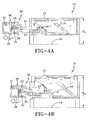
- FIGURES 4A and 4B show the same respective BOT drum arrangements as in FIGURES 1A, 1B, but with the present adjustable spacer invention 30 in place. More specifically, FIGURE 4A shows the BOT drum 10 in its fully collapsed mode such that the radius of the outer cylindrical surface 12 is R 1 .
- FIGURE 4B shows the cam 18 moved to the right such that the outer cylindrical surface 12 is at a larger radius R 2 in relation to the center line 14. Rightward motion of the cam 18 is limited to the distance 42 shown in FIGURE 4A, which is the maximum amount that the shaft 16 can move to the right before being stopped by the universal spacer invention 30.
- the universal spacer 30 is attached to the end of the traveling shaft 16, which extends through the opening 41 (FIGURE 3), by means of the cap screw bolt 44, as shown in FIGURES 4A and 4B.
- the distance 42 is controllable in a plurality of increments according to the pitch of the helices that define the positions of the holes 34 in the outer body portion 32 and the positions of the holes 40 in the inner portion 37 of the adjustable universal spacer 30.
- the adjustable plurality of increments of the distance 42 corresponds to the axial movement limits on the cam 18, for example corresponding to the width of the prior art spacer blocks 10 shown in FIGURES 1A, 1B.
- the distance 42 in FIGURE 4A is controlled by the relative positions of the outer body portion 32 of the universal spacer 30, which are affixed relative to one another by the pin 36 and a specific set of two holes 34 and two holes 40 (FIGURES 2 and 3) through which the pin is placed.
- a single traveling shaft 16 is shown, there are preferably two traveling shafts, with the not shown being disposed at the other end of the drum 10.
- Indicator numbers can be stamped or printed adjacent the holes 34 on the outer cylindrical body portion 32 and aligning with the holes 40 on the end of inner cylinder 37.
- the indicator numbers correspond to translational distances 42 shown in FIGURE 4A and allow rapid, repeatable fixing of the desired maximum translational distances 42.
Landscapes
- Engineering & Computer Science (AREA)
- Mechanical Engineering (AREA)
- Tyre Moulding (AREA)
Abstract
Description
Claims (10)
- A universal spacer (30) for varying the diameter of a tire tread breaker building drum (10) comprising a cylindrical outer body portion (32) having a plurality of sets of diametrically opposed holes (34) extending therethrough, an inner cylindrical portion (37) having at least two diametrically opposed holes (40) therethrough for varying the diameter of the tire tread breaker building drum (10), the inner cylindrical portion (37) being connected by at least one traveling shaft (16) to the building drum (10) for varying the diameter of the building drum (10), and means (36) for interconnecting the outer cylindrical body portion (32) with the inner cylindrical portion (37) to incrementally adjust the travel distance of the traveling shaft (16) and thereby control the diameter of the building drum (10).
- The universal spacer of claim 1 wherein the means for interconnecting the outer cylindrical body portion (32) with the inner body portion (37) is a pin (36).
- The universal spacer of claim 2 in which the pin (36) is slideably engagable through any two diametrically opposed holes (34) in the outer cylindrical body portion (32) and through at least two diametrically opposed holes (40) of the inner cylindrical body portion (37).
- The universal spacer of claim 2 or 3 in which one end of the pin (36) is affixed with a finger grasping flange (28) having a ring (39) attached thereto.
- The universal spacer of any of the preceding claims wherein the sets of diametrically opposing holes (34) in the outer cylindrical body portion (32) are regularly spaced and are situated so as to comprise a plurality of diametrically opposed hole sets through which the pin (36) can be inserted while also engaging at least two of the diametrically opposing holes (40) in the inner moveable cylindrical body portion (37) in such a way as to provide incremental and repeatable adjustment of the axial relationship of the outer cylindrical body portion (32) and the inner cylindrical body portion (37).
- The universal spacer of any of the preceding claims in which indicator numbers are located adjacent the holes (34, 40) so as to allow repeatable incremental adjustment of the relative axial positions of the outer cylindrical body portion (32) and the inner cylindrical body portion (37) by the means for interconnecting the outer cylindrical body portion (32) with the inner cylindrical portion (37).
- The universal spacer of any of the preceding claims in which the sets of diametrically opposing holes (34) in the outer cylindrical body portion (32) are arranged so as to comprise a regular double helical pattern about the circumference of the outer cylindrical body portion (32).
- A method of varying the diameter of a tire tread breaker building drum (10) comprising providing a cylindrical outer body portion (32) having a plurality of sets of diametrically opposed holes (34) extending therethrough, providing an inner cylindrical portion (37) of a having at least two diametrically opposed holes (40) therethrough, the inner cylindrical portion (37) being connected by a traveling shaft (16) to a cam component (18) of the building drum (10) for varying the diameter of the building drum (10), and interconnecting the outer cylindrical body portion (32) with the inner cylindrical portion (37) to incrementally adjust the travel distance of the traveling shaft (16) and thereby control the diameter of the building drum (10).
- The method of Claim 8 including interconnecting the outer cylindrical body portion (32) with the inner body portion (37) is accomplished with a pin (36).
- The method of Claim 9 including slideably engaging the pin (36) through any two diametrically opposed holes (34) in the outer cylindrical body portion (32) and through at least two diametrically opposed holes (40) of the inner cylindrical body portion (37).
Applications Claiming Priority (2)
| Application Number | Priority Date | Filing Date | Title |
|---|---|---|---|
| US10/219,181 US6776863B2 (en) | 2002-08-15 | 2002-08-15 | Universal spacer for tire building drum |
| US219181 | 2002-08-15 |
Publications (3)
| Publication Number | Publication Date |
|---|---|
| EP1389520A2 true EP1389520A2 (en) | 2004-02-18 |
| EP1389520A3 EP1389520A3 (en) | 2004-11-10 |
| EP1389520B1 EP1389520B1 (en) | 2006-07-19 |
Family
ID=30770636
Family Applications (1)
| Application Number | Title | Priority Date | Filing Date |
|---|---|---|---|
| EP03102450A Expired - Lifetime EP1389520B1 (en) | 2002-08-15 | 2003-08-06 | Universal spacer for tire building drum |
Country Status (4)
| Country | Link |
|---|---|
| US (1) | US6776863B2 (en) |
| EP (1) | EP1389520B1 (en) |
| CN (1) | CN100369739C (en) |
| DE (1) | DE60306854T2 (en) |
Cited By (2)
| Publication number | Priority date | Publication date | Assignee | Title |
|---|---|---|---|---|
| WO2011064500A1 (en) * | 2009-11-25 | 2011-06-03 | Societe De Technologie Michelin | Tyre blank assembly device including removable members |
| WO2016113510A1 (en) | 2015-01-16 | 2016-07-21 | Compagnie Generale Des Etablissements Michelin | Drum for producing a tyre blank |
Families Citing this family (1)
| Publication number | Priority date | Publication date | Assignee | Title |
|---|---|---|---|---|
| NL1025904C2 (en) * | 2004-04-08 | 2005-10-11 | Vmi Epe Holland | Seat belt drum. |
Family Cites Families (12)
| Publication number | Priority date | Publication date | Assignee | Title |
|---|---|---|---|---|
| US811035A (en) * | 1905-04-25 | 1906-01-30 | John Hartford Chidester | Adjustable washer. |
| BE503073A (en) * | 1950-05-08 | |||
| US2685353A (en) * | 1950-11-13 | 1954-08-03 | Us Army | Telescopic structure |
| US3207648A (en) * | 1962-02-01 | 1965-09-21 | Akron Standard Mold Co | Tire building apparatus |
| JPS55103942A (en) * | 1979-02-01 | 1980-08-08 | Bridgestone Corp | Forming drum for tyre |
| DE3312618A1 (en) * | 1983-04-08 | 1984-10-11 | Collmann GmbH & Co, Spezialmaschinenbau KG, 2400 Lübeck | DEVICE FOR DETERMINING THE TIRE POSITIONS OF A TIRE PROCESSING MACHINE |
| US5232542A (en) * | 1989-12-04 | 1993-08-03 | Summitomo Rubber Industries, Ltd. | Drum for assembling tire components |
| JPH0757537B2 (en) * | 1991-03-20 | 1995-06-21 | 株式会社森鐵工所 | Device for driving movable part in tire building drum device and tire building drum device using the same |
| DE59106601D1 (en) * | 1991-11-22 | 1995-11-02 | Werner Simon | Tightening unit. |
| US5259821A (en) * | 1991-12-27 | 1993-11-09 | Bryant Products, Inc. | Linear spacing device |
| US5618374A (en) * | 1994-02-10 | 1997-04-08 | Wyko, Inc. | Belt and tread drum for vehicle tire making machine |
| CN1157212A (en) * | 1996-02-17 | 1997-08-20 | 株式会社森铁工所 | Telescopic method and device for single-hole tyre forming drum |
-
2002
- 2002-08-15 US US10/219,181 patent/US6776863B2/en not_active Expired - Lifetime
-
2003
- 2003-08-06 EP EP03102450A patent/EP1389520B1/en not_active Expired - Lifetime
- 2003-08-06 DE DE60306854T patent/DE60306854T2/en not_active Expired - Fee Related
- 2003-08-15 CN CNB03154083XA patent/CN100369739C/en not_active Expired - Fee Related
Cited By (6)
| Publication number | Priority date | Publication date | Assignee | Title |
|---|---|---|---|---|
| WO2011064500A1 (en) * | 2009-11-25 | 2011-06-03 | Societe De Technologie Michelin | Tyre blank assembly device including removable members |
| CN102666078A (en) * | 2009-11-25 | 2012-09-12 | 米其林集团总公司 | Green tire assembly equipment including removable components |
| US9044908B2 (en) | 2009-11-25 | 2015-06-02 | Compagnie Generale Des Etablissements Michelin | Tire blank assembly device including removable members |
| CN102666078B (en) * | 2009-11-25 | 2015-11-25 | 米其林集团总公司 | Green tire assembly equipment including removable components |
| WO2016113510A1 (en) | 2015-01-16 | 2016-07-21 | Compagnie Generale Des Etablissements Michelin | Drum for producing a tyre blank |
| US10421241B2 (en) | 2015-01-16 | 2019-09-24 | Compagnie Generale Des Etablissements Michelin | Drum for producing a tire blank |
Also Published As
| Publication number | Publication date |
|---|---|
| CN100369739C (en) | 2008-02-20 |
| DE60306854T2 (en) | 2007-03-15 |
| EP1389520B1 (en) | 2006-07-19 |
| CN1486840A (en) | 2004-04-07 |
| US6776863B2 (en) | 2004-08-17 |
| US20040031569A1 (en) | 2004-02-19 |
| EP1389520A3 (en) | 2004-11-10 |
| DE60306854D1 (en) | 2006-08-31 |
Similar Documents
| Publication | Publication Date | Title |
|---|---|---|
| DE69526529T2 (en) | Improved drum for making belts and treads for a tire building machine | |
| US7704344B2 (en) | Tire building drum and tire building method | |
| EP1295704B1 (en) | Tire building drum | |
| US8708017B2 (en) | Assembly for altering the diameter of transfer ring or drum apparatus through a broad range | |
| US5223074A (en) | Bead locking apparatus for green tire building machine | |
| EP1286827B1 (en) | Expandable mandrel having adjustable width | |
| DE602005006370T2 (en) | A high-topped single-stage tire building drum | |
| EP2698243B1 (en) | Sleeveless tire building drum | |
| EP2868463B1 (en) | Tire building drum | |
| EP3638496B1 (en) | Method and apparatus for manufacturing tires | |
| EP3917765B1 (en) | Expandable belt and tread drum with reverse offset fingers | |
| CN1964838B (en) | Tire drum apparatus including turn-up mechanism for the manufacture of unvulcanized tires | |
| EP1491324B1 (en) | Method and apparatus for forming a raw tire | |
| DE69018306T2 (en) | Expandable tire building drum. | |
| EP1389520B1 (en) | Universal spacer for tire building drum | |
| US5772836A (en) | Turning apparatus for tire components | |
| EP0567742A2 (en) | Apparatus and method for uniformly enlarging or reducing the diameter of a cylindrical member | |
| US5164035A (en) | Tire building apparatus | |
| EP0342145B1 (en) | Expandable tire building drum | |
| DE69202000T2 (en) | Method and device for clamping a bead. | |
| KR20020069223A (en) | Tyre building drum | |
| US3778326A (en) | Tire-making drum | |
| DE60206630T2 (en) | CARKET COATING METHOD AND DRUM FOR PRODUCING A TIRE FOR VEHICLE WHEELS | |
| GB2223988A (en) | Manufacture of pneumatic tyres | |
| JP4763940B2 (en) | Tire belt layer forming device |
Legal Events
| Date | Code | Title | Description |
|---|---|---|---|
| PUAI | Public reference made under article 153(3) epc to a published international application that has entered the european phase |
Free format text: ORIGINAL CODE: 0009012 |
|
| AK | Designated contracting states |
Kind code of ref document: A2 Designated state(s): AT BE BG CH CY CZ DE DK EE ES FI FR GB GR HU IE IT LI LU MC NL PT RO SE SI SK TR |
|
| AX | Request for extension of the european patent |
Extension state: AL LT LV MK |
|
| PUAL | Search report despatched |
Free format text: ORIGINAL CODE: 0009013 |
|
| AK | Designated contracting states |
Kind code of ref document: A3 Designated state(s): AT BE BG CH CY CZ DE DK EE ES FI FR GB GR HU IE IT LI LU MC NL PT RO SE SI SK TR |
|
| AX | Request for extension of the european patent |
Extension state: AL LT LV MK |
|
| 17P | Request for examination filed |
Effective date: 20050510 |
|
| AKX | Designation fees paid |
Designated state(s): DE FR GB HU NL |
|
| 17Q | First examination report despatched |
Effective date: 20050704 |
|
| GRAP | Despatch of communication of intention to grant a patent |
Free format text: ORIGINAL CODE: EPIDOSNIGR1 |
|
| GRAS | Grant fee paid |
Free format text: ORIGINAL CODE: EPIDOSNIGR3 |
|
| GRAA | (expected) grant |
Free format text: ORIGINAL CODE: 0009210 |
|
| AK | Designated contracting states |
Kind code of ref document: B1 Designated state(s): DE FR GB HU NL |
|
| REG | Reference to a national code |
Ref country code: GB Ref legal event code: FG4D |
|
| REF | Corresponds to: |
Ref document number: 60306854 Country of ref document: DE Date of ref document: 20060831 Kind code of ref document: P |
|
| REG | Reference to a national code |
Ref country code: HU Ref legal event code: AG4A Ref document number: E000784 Country of ref document: HU |
|
| ET | Fr: translation filed | ||
| PLBE | No opposition filed within time limit |
Free format text: ORIGINAL CODE: 0009261 |
|
| STAA | Information on the status of an ep patent application or granted ep patent |
Free format text: STATUS: NO OPPOSITION FILED WITHIN TIME LIMIT |
|
| 26N | No opposition filed |
Effective date: 20070420 |
|
| PGFP | Annual fee paid to national office [announced via postgrant information from national office to epo] |
Ref country code: GB Payment date: 20070705 Year of fee payment: 5 |
|
| PGFP | Annual fee paid to national office [announced via postgrant information from national office to epo] |
Ref country code: DE Payment date: 20080829 Year of fee payment: 6 Ref country code: NL Payment date: 20080715 Year of fee payment: 6 |
|
| PGFP | Annual fee paid to national office [announced via postgrant information from national office to epo] |
Ref country code: FR Payment date: 20080807 Year of fee payment: 6 |
|
| PGFP | Annual fee paid to national office [announced via postgrant information from national office to epo] |
Ref country code: HU Payment date: 20080630 Year of fee payment: 6 |
|
| GBPC | Gb: european patent ceased through non-payment of renewal fee |
Effective date: 20080806 |
|
| PG25 | Lapsed in a contracting state [announced via postgrant information from national office to epo] |
Ref country code: GB Free format text: LAPSE BECAUSE OF NON-PAYMENT OF DUE FEES Effective date: 20080806 |
|
| REG | Reference to a national code |
Ref country code: NL Ref legal event code: V1 Effective date: 20100301 |
|
| REG | Reference to a national code |
Ref country code: FR Ref legal event code: ST Effective date: 20100430 |
|
| PG25 | Lapsed in a contracting state [announced via postgrant information from national office to epo] |
Ref country code: HU Free format text: LAPSE BECAUSE OF NON-PAYMENT OF DUE FEES Effective date: 20090807 Ref country code: FR Free format text: LAPSE BECAUSE OF NON-PAYMENT OF DUE FEES Effective date: 20090831 Ref country code: NL Free format text: LAPSE BECAUSE OF NON-PAYMENT OF DUE FEES Effective date: 20100301 Ref country code: DE Free format text: LAPSE BECAUSE OF NON-PAYMENT OF DUE FEES Effective date: 20100302 |