EP1388791A1 - Server, computer system, object management method, server control method, computer program - Google Patents
Server, computer system, object management method, server control method, computer program Download PDFInfo
- Publication number
- EP1388791A1 EP1388791A1 EP02718605A EP02718605A EP1388791A1 EP 1388791 A1 EP1388791 A1 EP 1388791A1 EP 02718605 A EP02718605 A EP 02718605A EP 02718605 A EP02718605 A EP 02718605A EP 1388791 A1 EP1388791 A1 EP 1388791A1
- Authority
- EP
- European Patent Office
- Prior art keywords
- time
- data
- user
- server
- main storage
- Prior art date
- Legal status (The legal status is an assumption and is not a legal conclusion. Google has not performed a legal analysis and makes no representation as to the accuracy of the status listed.)
- Withdrawn
Links
Images







Classifications
-
- G—PHYSICS
- G06—COMPUTING OR CALCULATING; COUNTING
- G06F—ELECTRIC DIGITAL DATA PROCESSING
- G06F15/00—Digital computers in general; Data processing equipment in general
-
- H—ELECTRICITY
- H04—ELECTRIC COMMUNICATION TECHNIQUE
- H04L—TRANSMISSION OF DIGITAL INFORMATION, e.g. TELEGRAPHIC COMMUNICATION
- H04L69/00—Network arrangements, protocols or services independent of the application payload and not provided for in the other groups of this subclass
- H04L69/30—Definitions, standards or architectural aspects of layered protocol stacks
- H04L69/32—Architecture of open systems interconnection [OSI] 7-layer type protocol stacks, e.g. the interfaces between the data link level and the physical level
- H04L69/322—Intralayer communication protocols among peer entities or protocol data unit [PDU] definitions
- H04L69/329—Intralayer communication protocols among peer entities or protocol data unit [PDU] definitions in the application layer [OSI layer 7]
-
- G—PHYSICS
- G06—COMPUTING OR CALCULATING; COUNTING
- G06F—ELECTRIC DIGITAL DATA PROCESSING
- G06F9/00—Arrangements for program control, e.g. control units
- G06F9/06—Arrangements for program control, e.g. control units using stored programs, i.e. using an internal store of processing equipment to receive or retain programs
- G06F9/44—Arrangements for executing specific programs
- G06F9/448—Execution paradigms, e.g. implementations of programming paradigms
- G06F9/4488—Object-oriented
- G06F9/4493—Object persistence
-
- H—ELECTRICITY
- H04—ELECTRIC COMMUNICATION TECHNIQUE
- H04L—TRANSMISSION OF DIGITAL INFORMATION, e.g. TELEGRAPHIC COMMUNICATION
- H04L67/00—Network arrangements or protocols for supporting network services or applications
- H04L67/50—Network services
- H04L67/60—Scheduling or organising the servicing of application requests, e.g. requests for application data transmissions using the analysis and optimisation of the required network resources
- H04L67/62—Establishing a time schedule for servicing the requests
-
- H—ELECTRICITY
- H04—ELECTRIC COMMUNICATION TECHNIQUE
- H04L—TRANSMISSION OF DIGITAL INFORMATION, e.g. TELEGRAPHIC COMMUNICATION
- H04L67/00—Network arrangements or protocols for supporting network services or applications
- H04L67/50—Network services
- H04L67/60—Scheduling or organising the servicing of application requests, e.g. requests for application data transmissions using the analysis and optimisation of the required network resources
- H04L67/61—Scheduling or organising the servicing of application requests, e.g. requests for application data transmissions using the analysis and optimisation of the required network resources taking into account QoS or priority requirements
Definitions
- the present invention relates to a server, a computer system, an object management method and a server control method that are appropriate to be used for a process using objects.
- networks such as the Internet and local area networks (LANs) have recently become popular.
- servers perform various processes requested by user terminals.
- web servers intended to provide services across networks permit user terminals to sequentially display web pages to navigate the steps for a service, receive requests made on the web pages, and perform processes requested by users.
- a server for Internet banking permits a user terminal to display a log-in page, and asks the user to enter a log-in ID and a password. After the entry of the log-in ID and the password, the server permits the user terminal to display a menu page, receives an item on the menu page selected by the user, and advances to a web page corresponding to the selected item, for example, "money transfer".
- the server When the user enters the account number of the destination and the amount to be transferred, the server permits the user terminal to display a transfer confirmation page. Then, when the server receives the user's confirmation of the transfer, the server performs the designated process, i.e., a money transfer process.
- a server which performs this process sequence or a so-called session, often employs a method of using an object for each user in order to process user requests.
- the object is used by the server to collectively manage data related to a session, i.e., user data, such as the log-in ID of a user, that is registered in advance, the contents of a process request, the process results, log data, such as process history, and the data that is generated during a session and is required for the following processes.
- An object is generated when a user performs the first session on the server, and at the second and following sessions, the same object is used, so that a continuous service can be provided based on the preceding sessions.
- the server includes, as data storage units, a memory device that constitutes the main storage and one or more hard disk drives that constitute the auxiliary storage, and the objects for individual users are appropriately sorted and stored either in the main storage or on the auxiliary storage. Based on the log-in ID that is entered by the user, the server retrieves, from the main storage or the auxiliary storage, an object corresponding to the user, and performs requested processes. Naturally, the response is slower when an object is stored on the auxiliary storage, that is, on a hard disk drive, because of the time that is necessary for retrieval.
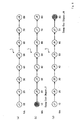
- Fig. 15A is a diagram showing the array of objects (J1 to J8) stored in the main storage at a specific time, beginning at the left with the object for which the last use time is the latest.
- the corresponding object (J5) is used, the last use time for the object (J5) is updated, and the position of the object (J5) in the array is changed, as is shown in Fig. 15B.
- Another method for managing objects in the main storage is a method whereby the access frequency history is employed for selecting an object to be swapped out (e.g., Japanese Unexamined Patent Publication No. Hei 6-4316).
- an object for which the access frequency (e.g., the total of in-use time) per unit time (e.g., the time that has elapsed since the object was swapped in) is the least is swapped out.
- a server especially one that provides a service for many users, may not always efficiently perform memory management. For example, for provision of a service for several ten thousands to several hundred thousands of users, a server may receive 500 or more process requests every minute.
- a user accesses such a server and when the user is performing a process sequence consisting of multiple steps along the web pages that are sequentially displayed as a result of the data entry by the user, e.g., is reading a specific web page, it may be necessary for the object of the user to be swapped out of the server's main storage if the server has received many process requests from other users.
- the processing means of a server uses an object stored in first object storage means, such as a semiconductor memory device, and performs a predetermined process.
- Use time prediction means predicts a use time whereat a currently used object is to be used by the processing means the next time. Based on the predicted use time, objects are transferred from the first object storage means to second object storage means, such as an auxiliary storage. Specifically, when an object stored in the first object storage means need to swapped out, of the currently stored objects, the object for which the predicted use time is the latest is swapped out, and is moved to the second object storage means. As a result, objects for which the predicted use time is the earliest are maintained in the first object storage means.
- the use time for an object When the use time for an object is predicted for each user, the skills of the individual users can be taken into account. And when the use time for an object is predicted for each of multiple steps constituting the process sequence, the process contents at individual steps (for either simple or complicated processes) can be taken into account. Objects for which the predicted use times have passed may be transferred from the first object storage means to the second object storage means.
- a time prediction unit predicts a use time whereat the object that have been used is to be used next by a processing unit to perform processes in accordance with requests, from user terminals, that are received by a request acceptance unit. Then, based on the time predicted by the time prediction unit, an object management unit manages the object stored in the main storage.
- the data output unit, the request acceptance unit, the main storage, the processing unit, the object management unit, and the time prediction unit may be provided integrally for a server. These components may also be separately distributed among multiple computers, so a system that is composed of computers collectively functions as a server.
- the period of time required from the data output to a user terminal by the data output unit until the next use of the object may be stored in a time data accumulation unit, so that the use time for a specific user can be predicted based on the time data accumulated for multiple users and those time data for the specific user. More specifically, for example, in the distribution of time data that have been accumulated, the index for a user for whom the time is to be predicted can be set by an index setting unit, and can be used to predict the use time for the user. Further, when only the latest time data for multiple users accumulated within a fixed time are employed, a time prediction can be made while taking into account fluctuation over time.
- an object management method comprises steps of: predicting the time at which each object stored in a main storage is to be used next; and when an object in the main storage must be swapped out, selecting from among objects in the main storage an object for which the predicted time is the latest and swapping the selected object out. Fluctuation over time can also be taken into consideration when predicting a time.
- a server control method comprises the steps of: accumulating response time data for a period extending from the output of process results in accordance with a process request by a user who has accessed a server via a network until a response is received from the user; employing the accumulated response time data to predict the time a response to the results that are output is received from the user; and swapping out an object from the main storage based on the predicted time.
- an index indicating the relative position of the response time data accumulated for the user can be set and can be employed for the prediction of a time.
- the time may be predicted based on a predetermined reference index, such as a default value.
- the index may also be updated each time response time data is accumulated, i.e., each time a user responds and a corresponding object is used.
- a computer program permits a computer, such as a server, to perform: a process for detecting a processing request command received from an external terminal; a process for predicting a time whereat the next process request command from the external terminal will be input as a response to the processing result that are output; and a process for managing objects, that is required to perform a process in accordance with the next request process command, by employing the predicted time.
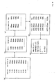
- Fig. 1 is a.diagram explaining a system configuration according to the embodiment of the invention.
- a network 20 such as the Internet or a LAN
- server 30 of a service provider.
- the terminals 10 are so-called PCs (Personal Computers), and need only comprise: a function for receiving data from the server 30 via the network 20; a browser function for displaying on the display screen of a monitor an image based on received data; a data input function, such as is provided by a pointing device or a keyboard, that enables a user to enter information and a request based on the contents of the display screen; and a function for transmitting to the server 30, via the network 20, the information entered using the data input function.
- PCs Personal Computers
- the server 30 comprises: a control block 31, for performing a process based on CPU instructions (not shown) based on a control program that is installed in advance; a memory (first object storage means, or main storage device) 32, such as a DRAM (Dynamic Random Access Memory); a hard disk drive (second object storage means or auxiliary storage device) 33; and a data transmitter/receiver 34, for transmitting and receiving data via the network 20.
- a control block 31 for performing a process based on CPU instructions (not shown) based on a control program that is installed in advance
- a memory first object storage means, or main storage device
- main storage device such as a DRAM (Dynamic Random Access Memory)
- second object storage means or auxiliary storage device such as a hard disk drive (second object storage means or auxiliary storage device) 33
- a data transmitter/receiver 34 for transmitting and receiving data via the network 20.
- the control block 31 includes: a request acceptance unit 36, for accepting a request that is issued by an external terminal 10 and received, via the network 20, by the data transmitter/receiver 34; a processing unit (processing means) 37, for performing a process in accordance with the received request; and a process result transmitter (data output unit) 38, for transmitting to the terminal 10 the process result obtained by the processing unit 37 via the data transmitter/receiver 34 and the network 20.
- a request acceptance unit 36 for accepting a request that is issued by an external terminal 10 and received, via the network 20, by the data transmitter/receiver 34
- processing unit 37 for performing a process in accordance with the received request
- a process result transmitter (data output unit) 38 for transmitting to the terminal 10 the process result obtained by the processing unit 37 via the data transmitter/receiver 34 and the network 20.
- the processing unit 37 includes: an object management unit 37a, for retrieving a required object from the memory 32, or for generating a new object, in order to perform a process in accordance with the request; a memory management unit (object management means, or an object management unit) 37b, for managing objects in the memory 32, e.g., swapping out an object from the memory 32 to the hard disk drive 33, or swapping in an object from the hard disk drive 33 to the memory 32. Further, when the objects are managed by the memory management unit 37b, the processing unit 37 predicts the next time an access will occur during the process sequence session performed for a user. Therefore, the control block 31 further comprises an access prediction unit (use time prediction means or a time prediction unit) 39.
- an access prediction unit use time prediction means or a time prediction unit
- the server 30 Since the server 30 performs the process requested by the user as a series of multiple steps, the server 30 provides, as so-called homepages, for the user's terminal 10, connected via the network 20 to the server 30, web pages that correspond to the individual steps of the process. For example, for Internet banking, in accordance with an entry received from the user terminal 10, the server 30 sequentially presents a web page for accepting log-in ID and password entries, a web page for accepting a process menu (e.g., a money transfer or an account balance inquiry) selected by a user following the log-in, a web page for accepting the entry of information (e.g., an account number for the money transfer destination, and the amount of money to be transferred) that is required for the execution of a process in accordance with the selected process menu, a web page for receiving from the user a confirmation for the process contents, and a web page for providing notification that the process has been completed.
- a process menu e.g., a money transfer or an account balance inquiry
- information e.g.,
- the processing unit 37 performs a predetermined process and presents the results to the user, and the process result transmitter 38 transmits data for a web page that permits the user to enter the request contents for the next process step.
- the data for displaying the web pages on the terminal 10 is stored on the hard disk drive (or another storage device) 33 of the server 30.
- the process results transmitter 38 reads, from the hard disk drive 33, data for a web page to be transmitted, e.g., HTML (Hypertext Markup Language) data, and the data transmitter/receiver 34 transmits this data, together with process result data provided by the processing unit 37, to the terminal 10 via the network 20.
- HTML Hypertext Markup Language
- the access prediction unit 39 predicts the time each user will access the next web page to each web page presented by the server 30. Specifically, a response time ⁇ is predicted that extends from the time whereat the server 30 transmits the data for a web page to the time (use time: hereinafter referred to as a use prediction time NA) whereat the terminal 10, which receives the data, displays the web page and the user, by reading the web page and completing the requested items thereon, transmits to the server 30, via the terminal 10, a command that the server 30 responds to by using an object for the user.
- a response time ⁇ is predicted that extends from the time whereat the server 30 transmits the data for a web page to the time (use time: hereinafter referred to as a use prediction time NA) whereat the terminal 10, which receives the data, displays the web page and the user, by reading the web page and completing the requested items thereon, transmits to the server 30, via the terminal 10, a command that the server 30 responds to by using an object for the user.
- the time required differs depending on the skills of the users, i.e., the practice they have had in using PCs, on whether the users have previously visited the web page presented by the server 30 and the frequency of such visits, and the users' reading and character input speeds. Further, when multiple web pages are presented, the response time ⁇ also differs even for the same user, and depends on the contents of a web page; for example, whether a web page is one on which only a log-in ID and a password need be entered, or is one on which a number of sentences, such as the rules for use, must be read or is one for which many entries are required.
- the response time ⁇ will be affected by the transfer speed of the network 20 and the processing speed of the server 30.
- the access time for each web page presented by the server 30 and the history data (time data) of the response time ⁇ that was actually required for each user are stored in the history data storage unit (time data accumulation unit) in the memory 32 or the hard disk drive 33.
- the actual response time ⁇ is the time duration required from the transmission by the server 30 of the data for each web page to the actual use of an object for processing the next request received from the user.
- the actual response time ⁇ is stored in the history data storage unit after quantization to seconds, for example (digitization), has been performed.
- Fig. 4 is a flowchart for the processing performed by the access prediction unit 39 to predict the response time ⁇ .
- the process results transmitter 38 transmits the data for a web page (output step), and the actual response time ⁇ , which is the time required for a response to the web page to be transmitted by the user terminals 10, is measured and is stored with the access time in the history data storage unit (not shown) (data accumulation step).
- N 1 and is hereinafter referred to as the past hour
- the probability distribution (the distribution of time data) of the actual response time ⁇ for the web page during the past hour is calculated. Specifically, as is shown in Fig.
- the actual response times ⁇ are grouped for each of multiple steps, for example, for each second.
- the number of accesses (users) pertinent to the groups is obtained, and the ratio of each group to the total access is calculated (step 102).
- these groups are sorted in the ascending order of the group IDs that are represented by the actual response times ⁇ , and the priority pr(n) is set for each group in accordance with the sorting order (step 103). Examples for the thus obtained probability distribution are shown in Figs. 5 to 7.
- Fig. 5 is a graph showing the probability distribution of the actual response times ⁇ for multiple users for a web page that includes simple input items for entries to be made at a user terminal 10.
- Fig. 6 is a graph showing the probability distribution for a web page containing complicated input items.
- Fig. 7 is a graph showing the probability distribution for a web page that includes input items that are not as simple as those in Fig. 5 and not complicated as those in Fig. 6. Since the input items are simple, in the probability distribution shown in Fig. 5, the variance in the response times ⁇ for all users is small. Whereas, in the probability distributions in Figs. 6 and 7, because of many entry items, a great difference in response time appears that is due to differing skills in the use of PCs, to reading speeds for sentences and to familiarity with the web pages, and the variance in the probability distribution is larger.
- the access prediction unit (index setting unit) 39 is so designed that it predicts a response time ⁇ of a user based on the probability distribution of the actual response time ⁇ .
- a characteristics parameter (index) cr is employed that represents the position (rate) of the actual response time ⁇ for a user in the probability distribution of the actual response time ⁇ .
- the characteristics parameter cr indicates the relative position of the user as measured from the side of the probability distribution where a priority pr(n) (an actual response time ⁇ ) is small.
- the characteristics parameter cr for the user is set based on the actual response times ⁇ that have been accumulated for the user. For example, based on the characteristics parameter cr for the actual response times ⁇ for a user relative to the past five accesses, the average value of the characteristics parameter cr, excepting the largest and the smallest variables, is set as the characteristics parameter cr for the user (index setting step). It is preferable that this characteristics parameter cr be set each time an actual response time ⁇ is accumulated for a user, i.e., each time an object is used, and that it be updated in real time.
- the rate (the rate for the number of accesses) for the groups are accumulated based on the equations in Fig. 3E, and when the accumulated value (hereinafter referred to as an accumulated rate: %) is equal to or greater than the characteristics parameter cr, the group ID of the current priority pr(n) is defined as the response time ⁇ for the user (step S104).
- the response time ⁇ for a user whose characteristics parameter cr is set as 75% is predicted to be "13 seconds", because the group ID for the priority pr(n) when the accumulated rate is equal to or greater than 75% is 13 seconds (in Fig.
- a response time ⁇ of six seconds is predicted both for a user whose characteristics parameter cr is set as 50% and a user whose characteristics parameter cr is set as 80%.
- a response time ⁇ of eight seconds is predicted for a user whose characteristics parameter cr is set as 50%
- a response time ⁇ of eleven seconds is predicted for a user whose characteristics parameter cr is set as 80%.
- the access prediction unit 39 predicts the time NA whereat an object is to be used to process the next user request, i.e., the next access time in a session. Based on a process request received from a user, the predicted use time NA is calculated when an object held in the memory 32 is used, and is stored in correlation with each object stored in the memory 32. For all the objects stored in the memory 32, the memory management unit 37b generates an object array L, shown in Fig. 8 as an example, beginning with the latest predicted use time NA, and manages the objects based on this object array L.
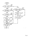
- FIG. 9 is a flowchart showing the basic object management processing performed by the processing unit 37.
- the server 30 employs the log-in ID entered by the user terminal 10 to determine whether the object corresponding to the log-in ID is already present in the server 30 (step S201).
- step S202 a check is performed to determine whether the object is present in the memory 32 (step S202), and when the object is present in the memory 32, program control advances to step S206 and a process consonant with the request is performed by the processing unit 37.
- step S203 a check is performed to determine whether there is enough free space in the memory 32 to swap in the object from the hard disk drive 33 to the memory 32. If there is not sufficient space in the memory 32, at step S204 (a swap-out step and an execution step) a swap-out process that will be described later is performed, and at step S205, the object is swapped in from the hard disk drive 33 to the memory 32. When there is sufficient free space, at step S205 the object is swapped in to the memory 32. Then, at step S206, the processing unit 37 uses the object that has been swapped in to the memory 32 to perform a process in accordance with the request received from the user terminal 10.
- step S201 When it is ascertained at step S201 that the object is not present in the server 30, program control is shifted to step S210, and a check is performed to determine whether there is large enough free space to generate a new object.
- step S211 a swap-out step and an execution step
- the swap-out process that will be described later is performed
- step S212 the object management unit 37a generates a new object in the memory 32.
- step S212 a new object is generated in the memory 32.
- the processing unit 37 uses the object generated in the memory 32 to perform a process in accordance with the request received from the user terminal 10.
- the predicted use time NA obtained by the access prediction unit 39 is employed to perform the swap-out process at step S204 or S211.
- Fig. 10 is a flowchart for the swap-out processing.
- the predicted use time NA (O) is fetched for the first object (O) in the array L of the objects arranged in the memory 32 beginning with the earliest predicted use time NA (step S301).
- a check is then performed to determine whether at the current time, held by an internal clock (not shown), the predicted use time NA (O) has passed (step S302).
- the first object (O) is swapped out (step S303).
- the last object (O) in the object array L (the object having the latest time) is selected (object specification step) and is swapped out (step S304).
- the processing in Fig. 10 is performed for the object array L in the state in Fig. 8A when the object swap-out process must be performed.
- Fig. 11 is a flowchart showing a method for updating the object array L in the memory 32 for the swap-in process at step S205 or for the process for generating a new object at step S212.
- the access prediction unit 39 predicts the use time NA(A) for an object (A) that is to be swapped in or is to be generated (prediction step S401).
- the characteristics parameter cr set for the user is employed to predict the use time NA(A) for a web page currently being accessed by the user terminal 10.
- the first object (O) is fetched from the object array L comprising all the objects stored in the memory 32 (step S402).
- a check is then performed to determine whether the fetched object (O) is a null (step S403).
- the object (O) in question is inserted at the last of the object array L (step S404).
- a check is performed to determine whether the predicted use time NA(O) for the fetched object (O) is greater than the predicted use time NA(A) for the object (A).
- step S402 When the predicted use time NA(O) is not greater than the predicted use time NA(A), program control returns to step S402, the next object (O) is fetched from the object array L, and the process beginning at the step S403 is repeated.
- the objects (O) of the object array L are sequentially examined, and when it is ascertained at step S405 that the predicted use time NA(O) of a specific object (O) is greater than the predicted use time NA(A) of the object (A), the object (A) is inserted before the specific object (O) in the object array L (step S406).
- the object (A) that is swapped in or that is generated is inserted into the object array L, and the object array L is updated.
- Figs. 12A and 12B are diagrams showing an example of the updating performed for the object array L.
- a log-normal distribution as shown in Fig. 13 is employed as the probability distribution required to predict the response time ⁇ for a user.
- the characteristics parameter cr for the users is set to 99%, based on the log-normal probability distribution.
- server 30 which manages objects based on the algorithm employing predicted use time NA
- a server (not shown), which manages objects based on a conventional LRU-type algorithm (hereinafter referred to as an LRU algorithm)
- LRU algorithm a server (not shown), which manages objects based on a conventional LRU-type algorithm (hereinafter referred to as an LRU algorithm)
- a relative reduction ratio 1 - the number of swap-outs by the algorithm using the predicted use time NA/the number of swap-outs by the LRU algorithm.
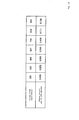
- Fig. 14 is a table showing the result of the simulations.
- the number of swap-outs for the server 30 that employs the algorithm using the predicted use time NA is reduced compared with that for the server that employs the LRU algorithm. Therefore, it is found that the algorithm using the predicted use time NA is more effective, especially for a server that receives a large number of requests per unit time, i.e., a server that is accessed frequently, since the number of swap-outs becomes relatively smaller.
- the server 30 predicts the time whereat the user will issue the next request, i.e., the predicted use time NA for the object stored in the server 30, and manages the objects stored in the memory 32 based on the predicted use time NA.
- the swap-out of an object in the memory 32 basically the object having the latest predicted use time NA is swapped out. Therefore, only objects having early predicted use times NA, i.e., only objects that will most probably be used in the near future, are present in the memory 32.
- the swapping out is performed simply by beginning with the object having the oldest last use time.
- this object is inserted at the top of the object array, and the object having the oldest last use time is swapped out from the tail of the object array.
- an object in use may be swapped out for the sake of other objects used for accesses by other users. In this case, the contents of web pages that such other users are accessing are not taken into account at all. Therefore, when this user advances to the next step, the object must be swapped in again after another object has been swapped out, and as a result, unnecessary swap-ins and swap-outs must be performed.
- the number of unnecessary swap-ins and swap-outs can be minimized, and the efficiency of the server 30 can be increased.
- a user can quickly obtain a response from the server 30, the factors that cause a user to feel dissatisfied can be reduced, and the quality of the service can be improved.
- the predicted use time NA is obtained not only by using the characteristics parameter cr that is set based on the skill of each user but also based on the contents of the web page each user is accessing, the time can be predicted more accurately. Furthermore, the history data for the past N hours (e.g., one hour) is extracted and is used for the prediction of the use time NA. Therefore, even when the total number of accesses and the degree of the traffic on the network 20 fluctuate depending on time, this can be taken into account while the prediction is made. Further, since an object whose predicted use time NA, relative to the current time, has passed is swapped out, an object, such as an object for which a session has been left off, that is present in the memory 32 even though it is not being used can be removed. This can also contribute to efficient object management.
- the characteristics parameter cr set for each user is used for the algorithm for setting the predicted use time NA. So long as the use time NA can be predicted, another algorithm may also be employed. Further, in the swap-out process, an object whose predicted use time NA has passed is swapped out through the process in Fig. 10. However, the same process may be performed for each predetermined period of time. As a result, free space in the memory 32 can be obtained in advance by swapping out unnecessary objects. A specific amount of history' data for determining the probability distribution is required to predict the use time NA. However, when the server 30 is activated, the history data may not be present or may be insufficient. In this case, the LRU method may be employed until a sufficient amount of history data has been accumulated, and after a satisfactory amount of history data has been accumulated, the employment of the predicted use time NA may be begun.
- the server 30 performs an Internet banking process.
- the use of the present invention is not limited to this example, and it can be applied to processing of arbitrary types and contents.
- the configuration of the embodiment may be rearranged or modified to provide another configuration.
- the operation efficiency of the server can be increased, and the service provided for a user can be improved.
Landscapes
- Engineering & Computer Science (AREA)
- Software Systems (AREA)
- Theoretical Computer Science (AREA)
- Computer Networks & Wireless Communication (AREA)
- Signal Processing (AREA)
- General Physics & Mathematics (AREA)
- General Engineering & Computer Science (AREA)
- Physics & Mathematics (AREA)
- Computer Security & Cryptography (AREA)
- Computer Hardware Design (AREA)
- Computer And Data Communications (AREA)
- Information Transfer Between Computers (AREA)
- Memory System Of A Hierarchy Structure (AREA)
Abstract
It is one object of the present invention to provide a server, a
computer system that can efficiently operate a server, an object management
method and a server control method.
For each web page that is presented to a user terminal, a server
predicts the times whereat users will issue the next requests, i.e., the
times NA wherat objects held by the server will be used, and manages
objects stored in the main storage based on predicted use times NA. In the
process employed for swapping an object out of the main storage, basically
the object is swapped out whose predicted use time NA is the latest.
Description
The present invention relates to a server, a computer
system, an object management method and a server control
method that are appropriate to be used for a process using
objects.
As is well known, networks such as the Internet and local
area networks (LANs) have recently become popular. Across
these networks, servers perform various processes
requested by user terminals.
Specifically, web servers intended to provide services across networks permit user terminals to sequentially display web pages to navigate the steps for a service, receive requests made on the web pages, and perform processes requested by users. As an example, a server for Internet banking permits a user terminal to display a log-in page, and asks the user to enter a log-in ID and a password. After the entry of the log-in ID and the password, the server permits the user terminal to display a menu page, receives an item on the menu page selected by the user, and advances to a web page corresponding to the selected item, for example, "money transfer". When the user enters the account number of the destination and the amount to be transferred, the server permits the user terminal to display a transfer confirmation page. Then, when the server receives the user's confirmation of the transfer, the server performs the designated process, i.e., a money transfer process.
Specifically, web servers intended to provide services across networks permit user terminals to sequentially display web pages to navigate the steps for a service, receive requests made on the web pages, and perform processes requested by users. As an example, a server for Internet banking permits a user terminal to display a log-in page, and asks the user to enter a log-in ID and a password. After the entry of the log-in ID and the password, the server permits the user terminal to display a menu page, receives an item on the menu page selected by the user, and advances to a web page corresponding to the selected item, for example, "money transfer". When the user enters the account number of the destination and the amount to be transferred, the server permits the user terminal to display a transfer confirmation page. Then, when the server receives the user's confirmation of the transfer, the server performs the designated process, i.e., a money transfer process.
A server, which performs this process sequence or a
so-called session, often employs a method of using an
object for each user in order to process user requests.
The object is used by the server to collectively manage
data related to a session, i.e., user data, such as the
log-in ID of a user, that is registered in advance, the
contents of a process request, the process results, log
data, such as process history, and the data that is
generated during a session and is required for the
following processes. An object is generated when a user
performs the first session on the server, and at the
second and following sessions, the same object is used, so
that a continuous service can be provided based on the
preceding sessions.
The server includes, as data storage units, a memory
device that constitutes the main storage and one or more
hard disk drives that constitute the auxiliary storage,
and the objects for individual users are appropriately
sorted and stored either in the main storage or on the
auxiliary storage. Based on the log-in ID that is entered
by the user, the server retrieves, from the main storage
or the auxiliary storage, an object corresponding to the
user, and performs requested processes. Naturally, the
response is slower when an object is stored on the
auxiliary storage, that is, on a hard disk drive, because
of the time that is necessary for retrieval.
Since the memory capacity of the server is physically
limited, the number of objects that can be stored in the
main storage is accordingly limited. Therefore, when an
object is to be retrieved from an auxiliary storage and
loaded into the main storage, or when a new object is to
be generated in the main storage, if there is not enough
free space in the main storage, some of the objects
currently stored in the main storage are moved to the
auxiliary storage to provide additional free memory space,
and the object retrieved from the auxiliary storage is
stored therein. This movement of objects from the main
storage to an auxiliary storage is called swap-out. While
the retrieval of objects, from an auxiliary storage into
free space in the main storage, is called swap-in.
Conventionally, the LRU (Least Recently Used) method is
often employed for the management of objects in the main
storage. According to the LRU method, the objects are
swapped out of the main storage beginning with the object
for which the time of its preceding use (the last time
used) is the oldest.
For example, Fig. 15A is a diagram showing the array of objects (J1 to J8) stored in the main storage at a specific time, beginning at the left with the object for which the last use time is the latest. Upon receiving a process request from a user, the corresponding object (J5) is used, the last use time for the object (J5) is updated, and the position of the object (J5) in the array is changed, as is shown in Fig. 15B. That is, since the object (J5) was recently used for the process and its last use time is the latest, it comes first in the array (left end,in Fig. 15B). Further, when swapping out of objects is to be performed because free memory space is insufficient for the generation of a new object (not shown) or the retrieval of an object from an auxiliary storage, as is shown in Fig. 15C, of the objects (J1) to (J8) currently stored in the main storage, the object (J8), for which the last use time is the oldest is swapped out, and moved out of the main storage to the auxiliary storage.
For example, Fig. 15A is a diagram showing the array of objects (J1 to J8) stored in the main storage at a specific time, beginning at the left with the object for which the last use time is the latest. Upon receiving a process request from a user, the corresponding object (J5) is used, the last use time for the object (J5) is updated, and the position of the object (J5) in the array is changed, as is shown in Fig. 15B. That is, since the object (J5) was recently used for the process and its last use time is the latest, it comes first in the array (left end,in Fig. 15B). Further, when swapping out of objects is to be performed because free memory space is insufficient for the generation of a new object (not shown) or the retrieval of an object from an auxiliary storage, as is shown in Fig. 15C, of the objects (J1) to (J8) currently stored in the main storage, the object (J8), for which the last use time is the oldest is swapped out, and moved out of the main storage to the auxiliary storage.
Another method for managing objects in the main storage is
a method whereby the access frequency history is employed
for selecting an object to be swapped out (e.g., Japanese
Unexamined Patent Publication No. Hei 6-4316). According
to this method, unlike the above method whereby the object
for which the last use time is the oldest is swapped out,
an object for which the access frequency (e.g., the total
of in-use time) per unit time (e.g., the time that has
elapsed since the object was swapped in) is the least is
swapped out.
However, according to the above described former methods,
a server, especially one that provides a service for many
users, may not always efficiently perform memory
management. For example, for provision of a service for
several ten thousands to several hundred thousands of
users, a server may receive 500 or more process requests
every minute. When a user accesses such a server and when
the user is performing a process sequence consisting of
multiple steps along the web pages that are sequentially
displayed as a result of the data entry by the user, e.g.,
is reading a specific web page, it may be necessary for
the object of the user to be swapped out of the server's
main storage if the server has received many process
requests from other users. In such a case, when the user
has read a web page and has posted data to move to the
next web page, the server must swap the user's object in
the main storage, so that the display of the next page is
delayed. Accordingly, there may be a noticeable response
delay and the user may become dissatisfied with the
service provided by the server. Therefore, it is demanded
that service providers eliminate the occurrence of such
delays, and as a consequence, continuing studies of many
methods, including methods for responding to requests
quickly, have been conducted for reducing the loads
imposed on servers and for ensuring the servers are
operated efficiently.
To resolve the technical shortcomings, it is one object of the present invention to provide a server, a computer system for efficiently operating a server, an object management method and a server control method.
To resolve the technical shortcomings, it is one object of the present invention to provide a server, a computer system for efficiently operating a server, an object management method and a server control method.
To achieve the above object of the invention, upon
receiving a request from a user via a network, the
processing means of a server uses an object stored in
first object storage means, such as a semiconductor memory
device, and performs a predetermined process. Use time
prediction means predicts a use time whereat a currently
used object is to be used by the processing means the next
time. Based on the predicted use time, objects are
transferred from the first object storage means to second
object storage means, such as an auxiliary storage.
Specifically, when an object stored in the first object
storage means need to swapped out, of the currently stored
objects, the object for which the predicted use time is
the latest is swapped out, and is moved to the second
object storage means. As a result, objects for which the
predicted use time is the earliest are maintained in the
first object storage means.
When the use time for an object is predicted for each user, the skills of the individual users can be taken into account. And when the use time for an object is predicted for each of multiple steps constituting the process sequence, the process contents at individual steps (for either simple or complicated processes) can be taken into account.
Objects for which the predicted use times have passed may be transferred from the first object storage means to the second object storage means.
When the use time for an object is predicted for each user, the skills of the individual users can be taken into account. And when the use time for an object is predicted for each of multiple steps constituting the process sequence, the process contents at individual steps (for either simple or complicated processes) can be taken into account.
Objects for which the predicted use times have passed may be transferred from the first object storage means to the second object storage means.
In a computer system according to the present invention,
after a data output unit outputs data, a time prediction
unit predicts a use time whereat the object that have been
used is to be used next by a processing unit to perform
processes in accordance with requests, from user
terminals, that are received by a request acceptance unit.
Then, based on the time predicted by the time prediction
unit, an object management unit manages the object stored
in the main storage.
The data output unit, the request acceptance unit, the main storage, the processing unit, the object management unit, and the time prediction unit may be provided integrally for a server. These components may also be separately distributed among multiple computers, so a system that is composed of computers collectively functions as a server.
The data output unit, the request acceptance unit, the main storage, the processing unit, the object management unit, and the time prediction unit may be provided integrally for a server. These components may also be separately distributed among multiple computers, so a system that is composed of computers collectively functions as a server.
The period of time required from the data output to a user
terminal by the data output unit until the next use of the
object may be stored in a time data accumulation unit, so
that the use time for a specific user can be predicted
based on the time data accumulated for multiple users and
those time data for the specific user.
More specifically, for example, in the distribution of time data that have been accumulated, the index for a user for whom the time is to be predicted can be set by an index setting unit, and can be used to predict the use time for the user. Further, when only the latest time data for multiple users accumulated within a fixed time are employed, a time prediction can be made while taking into account fluctuation over time.
More specifically, for example, in the distribution of time data that have been accumulated, the index for a user for whom the time is to be predicted can be set by an index setting unit, and can be used to predict the use time for the user. Further, when only the latest time data for multiple users accumulated within a fixed time are employed, a time prediction can be made while taking into account fluctuation over time.
According to the invention, an object management method
comprises steps of: predicting the time at which each
object stored in a main storage is to be used next; and
when an object in the main storage must be swapped out,
selecting from among objects in the main storage an object
for which the predicted time is the latest and swapping
the selected object out. Fluctuation over time can also
be taken into consideration when predicting a time.
According to the invention, a server control method
comprises the steps of: accumulating response time data
for a period extending from the output of process results
in accordance with a process request by a user who has
accessed a server via a network until a response is
received from the user; employing the accumulated response
time data to predict the time a response to the results
that are output is received from the user; and swapping
out an object from the main storage based on the predicted
time.
At this time, in the distribution of the response time data not only for a pertinent user but also for other users, an index indicating the relative position of the response time data accumulated for the user can be set and can be employed for the prediction of a time. For a user for whom an index has not been set, the time may be predicted based on a predetermined reference index, such as a default value. The index may also be updated each time response time data is accumulated, i.e., each time a user responds and a corresponding object is used.
At this time, in the distribution of the response time data not only for a pertinent user but also for other users, an index indicating the relative position of the response time data accumulated for the user can be set and can be employed for the prediction of a time. For a user for whom an index has not been set, the time may be predicted based on a predetermined reference index, such as a default value. The index may also be updated each time response time data is accumulated, i.e., each time a user responds and a corresponding object is used.
According to the present invention, a computer program
permits a computer, such as a server, to perform: a
process for detecting a processing request command
received from an external terminal; a process for
predicting a time whereat the next process request command
from the external terminal will be input as a response to
the processing result that are output; and a process for
managing objects, that is required to perform a process in
accordance with the next request process command, by
employing the predicted time.
The preferred embodiment of the present invention will now
be described in detail while referring to the accompanying
drawings.
Fig. 1 is a.diagram explaining a system configuration according to the embodiment of the invention. As is shown in Fig. 1,multiple user terminals 10 are connected via a
network 20, such as the Internet or a LAN, to a server (a
computer system or a computer) 30 of a service provider.
The terminals 10 are so-called PCs (Personal Computers),
and need only comprise: a function for receiving data from
the server 30 via the network 20; a browser function for
displaying on the display screen of a monitor an image
based on received data; a data input function, such as is
provided by a pointing device or a keyboard, that enables
a user to enter information and a request based on the
contents of the display screen; and a function for
transmitting to the server 30, via the network 20, the
information entered using the data input function.
Fig. 1 is a.diagram explaining a system configuration according to the embodiment of the invention. As is shown in Fig. 1,
As is shown in Fig. 2, the server 30 comprises: a control
block 31, for performing a process based on CPU
instructions (not shown) based on a control program that
is installed in advance; a memory (first object storage
means, or main storage device) 32, such as a DRAM (Dynamic
Random Access Memory); a hard disk drive (second object
storage means or auxiliary storage device) 33; and a data
transmitter/receiver 34, for transmitting and receiving
data via the network 20.
The control block 31 includes: a request acceptance unit
36, for accepting a request that is issued by an external
terminal 10 and received, via the network 20, by the data
transmitter/receiver 34; a processing unit (processing
means) 37, for performing a process in accordance with the
received request; and a process result transmitter (data
output unit) 38, for transmitting to the terminal 10 the
process result obtained by the processing unit 37 via the
data transmitter/receiver 34 and the network 20.
The processing unit 37 includes: an object management unit
37a, for retrieving a required object from the memory 32,
or for generating a new object, in order to perform a
process in accordance with the request; a memory
management unit (object management means, or an object
management unit) 37b, for managing objects in the memory
32, e.g., swapping out an object from the memory 32 to the
hard disk drive 33, or swapping in an object from the hard
disk drive 33 to the memory 32.
Further, when the objects are managed by thememory
management unit 37b, the processing unit 37 predicts the
next time an access will occur during the process sequence
session performed for a user. Therefore, the control
block 31 further comprises an access prediction unit (use
time prediction means or a time prediction unit) 39.
Further, when the objects are managed by the
Since the server 30 performs the process requested by the
user as a series of multiple steps, the server 30
provides, as so-called homepages, for the user's terminal
10, connected via the network 20 to the server 30, web
pages that correspond to the individual steps of the
process. For example, for Internet banking, in accordance
with an entry received from the user terminal 10, the
server 30 sequentially presents a web page for accepting
log-in ID and password entries, a web page for accepting a
process menu (e.g., a money transfer or an account balance
inquiry) selected by a user following the log-in, a web
page for accepting the entry of information (e.g., an
account number for the money transfer destination, and the
amount of money to be transferred) that is required for
the execution of a process in accordance with the selected
process menu, a web page for receiving from the user a
confirmation for the process contents, and a web page for
providing notification that the process has been
completed.
In the server 30, therefore, based on a process request
command and parameters that are included in the request
(request contents data) received by the request acceptance
unit 36, the processing unit 37 performs a predetermined
process and presents the results to the user, and the
process result transmitter 38 transmits data for a web
page that permits the user to enter the request contents
for the next process step.
In this case; the data for displaying the web pages on the terminal 10 is stored on the hard disk drive (or another storage device) 33 of theserver 30. The process results
transmitter 38 reads, from the hard disk drive 33, data
for a web page to be transmitted, e.g., HTML (Hypertext
Markup Language) data, and the data transmitter/receiver
34 transmits this data, together with process result data
provided by the processing unit 37, to the terminal 10 via
the network 20.
In this case; the data for displaying the web pages on the terminal 10 is stored on the hard disk drive (or another storage device) 33 of the
The access prediction unit 39 predicts the time each user
will access the next web page to each web page presented
by the server 30. Specifically, a response time α is
predicted that extends from the time whereat the server 30
transmits the data for a web page to the time (use time:
hereinafter referred to as a use prediction time NA)
whereat the terminal 10, which receives the data, displays
the web page and the user, by reading the web page and
completing the requested items thereon, transmits to the
server 30, via the terminal 10, a command that the server
30 responds to by using an object for the user.
This is necessary because there is a great difference in the response times α required by users when reading a page, even the same page, and entering required data. The time required differs depending on the skills of the users, i.e., the practice they have had in using PCs, on whether the users have previously visited the web page presented by theserver 30 and the frequency of such
visits, and the users' reading and character input speeds.
Further, when multiple web pages are presented, the
response time α also differs even for the same user, and
depends on the contents of a web page; for example,
whether a web page is one on which only a log-in ID and a
password need be entered, or is one on which a number of
sentences, such as the rules for use, must be read or is
one for which many entries are required. In addition,
since the number of users of the network 20 and the server
30 will differ greatly, depending on the time period, such
as late at night, early in the morning or during the
daytime, the response time α will be affected by the
transfer speed of the network 20 and the processing speed
of the server 30.
This is necessary because there is a great difference in the response times α required by users when reading a page, even the same page, and entering required data. The time required differs depending on the skills of the users, i.e., the practice they have had in using PCs, on whether the users have previously visited the web page presented by the
In the server 30, for all users, as is shown in Fig. 3A,
the access time for each web page presented by the server
30 and the history data (time data) of the response time β
that was actually required for each user are stored in the
history data storage unit (time data accumulation unit) in
the memory 32 or the hard disk drive 33. The actual
response time β is the time duration required from the
transmission by the server 30 of the data for each web
page to the actual use of an object for processing the
next request received from the user. The actual response
time β is stored in the history data storage unit after
quantization to seconds, for example (digitization), has
been performed.
Fig. 4 is a flowchart for the processing performed by the
access prediction unit 39 to predict the response time α.
First, immediately after the server 30 is activated, as is
described above, for all the users who have accessed the
server 30, the process results transmitter 38 transmits
the data for a web page (output step), and the actual
response time β, which is the time required for a response
to the web page to be transmitted by the user terminals
10, is measured and is stored with the access time in the
history data storage unit (not shown) (data accumulation
step).
When in accordance with a request from a user the server
30 transmits the data for a web page to a user terminal 10
via the network 20, first, the history data for the
processes that were performed for the same web page during
the past predetermined N hours (in this embodiment, N = 1
and is hereinafter referred to as the past hour) is
extracted from the history data storage unit (not shown)
(step S101). In Fig. 3B, at the current time, 9:00, for
example, the history data for the processes that were
performed during the past hour, i.e., after 8:00, are
extracted.
Then, based on the extracted history data, the probability distribution (the distribution of time data) of the actual response time β for the web page during the past hour is calculated. Specifically, as is shown in Fig. 3C, the actual response times β are grouped for each of multiple steps, for example, for each second. The number of accesses (users) pertinent to the groups is obtained, and the ratio of each group to the total access is calculated (step 102). Further, as is shown in Fig. 3D, these groups are sorted in the ascending order of the group IDs that are represented by the actual response times β, and the priority pr(n) is set for each group in accordance with the sorting order (step 103).
Examples for the thus obtained probability distribution are shown in Figs. 5 to 7. Fig. 5 is a graph showing the probability distribution of the actual response times β for multiple users for a web page that includes simple input items for entries to be made at auser terminal 10.
Fig. 6 is a graph showing the probability distribution for
a web page containing complicated input items. Fig. 7 is
a graph showing the probability distribution for a web
page that includes input items that are not as simple as
those in Fig. 5 and not complicated as those in Fig. 6.
Since the input items are simple, in the probability
distribution shown in Fig. 5, the variance in the response
times β for all users is small. Whereas, in the
probability distributions in Figs. 6 and 7, because of
many entry items, a great difference in response time
appears that is due to differing skills in the use of PCs,
to reading speeds for sentences and to familiarity with
the web pages, and the variance in the probability
distribution is larger.
Then, based on the extracted history data, the probability distribution (the distribution of time data) of the actual response time β for the web page during the past hour is calculated. Specifically, as is shown in Fig. 3C, the actual response times β are grouped for each of multiple steps, for example, for each second. The number of accesses (users) pertinent to the groups is obtained, and the ratio of each group to the total access is calculated (step 102). Further, as is shown in Fig. 3D, these groups are sorted in the ascending order of the group IDs that are represented by the actual response times β, and the priority pr(n) is set for each group in accordance with the sorting order (step 103).
Examples for the thus obtained probability distribution are shown in Figs. 5 to 7. Fig. 5 is a graph showing the probability distribution of the actual response times β for multiple users for a web page that includes simple input items for entries to be made at a
The access prediction unit (index setting unit) 39 is so
designed that it predicts a response time α of a user
based on the probability distribution of the actual
response time β. For this prediction, in this embodiment,
a characteristics parameter (index) cr is employed that
represents the position (rate) of the actual response time
β for a user in the probability distribution of the actual
response time β. The characteristics parameter cr
indicates the relative position of the user as measured
from the side of the probability distribution where a
priority pr(n) (an actual response time β) is small.
Until the accesses by a user have reached a predetermined number of times, the default value (standard index) held in advance by theaccess prediction unit 39, i.e., cr =
90%, is employed as the characteristics parameter cr.
Then, when the accesses by the user have reached the
predetermined number of times, the characteristics
parameter cr for the user is set based on the actual
response times β that have been accumulated for the user.
For example, based on the characteristics parameter cr for
the actual response times β for a user relative to the
past five accesses, the average value of the
characteristics parameter cr, excepting the largest and
the smallest variables, is set as the characteristics
parameter cr for the user (index setting step). It is
preferable that this characteristics parameter cr be set
each time an actual response time β is accumulated for a
user, i.e., each time an object is used, and that it be
updated in real time.
Until the accesses by a user have reached a predetermined number of times, the default value (standard index) held in advance by the
In order to predict the response time α for a user,
beginning at the small priority pr(n) side, the rate (the
rate for the number of accesses) for the groups are
accumulated based on the equations in Fig. 3E, and when
the accumulated value (hereinafter referred to as an
accumulated rate: %) is equal to or greater than the
characteristics parameter cr, the group ID of the current
priority pr(n) is defined as the response time α for the
user (step S104).
As a specific example, in the probability distribution in Fig. 7, the response time α for a user whose characteristics parameter cr is set as 75% is predicted to be "13 seconds", because the group ID for the priority pr(n) when the accumulated rate is equal to or greater than 75% is 13 seconds (in Fig. 7, the rates are accumulated as 10% + 15% + 30% + 25% = 80%, beginning at the side of the probability distribution where the priority pr(n) is small). Similarly, in the probability distribution in Fig. 5, a response time α of six seconds is predicted both for a user whose characteristics parameter cr is set as 50% and a user whose characteristics parameter cr is set as 80%. Further, in the probability distribution in Fig. 6, a response time α of eight seconds is predicted for a user whose characteristics parameter cr is set as 50%, and a response time α of eleven seconds is predicted for a user whose characteristics parameter cr is set as 80%.
As a specific example, in the probability distribution in Fig. 7, the response time α for a user whose characteristics parameter cr is set as 75% is predicted to be "13 seconds", because the group ID for the priority pr(n) when the accumulated rate is equal to or greater than 75% is 13 seconds (in Fig. 7, the rates are accumulated as 10% + 15% + 30% + 25% = 80%, beginning at the side of the probability distribution where the priority pr(n) is small). Similarly, in the probability distribution in Fig. 5, a response time α of six seconds is predicted both for a user whose characteristics parameter cr is set as 50% and a user whose characteristics parameter cr is set as 80%. Further, in the probability distribution in Fig. 6, a response time α of eight seconds is predicted for a user whose characteristics parameter cr is set as 50%, and a response time α of eleven seconds is predicted for a user whose characteristics parameter cr is set as 80%.
Based on the thus predicted response time α for a user,
the predicted time NA whereat an object is to be used to
process the next user request is obtained using the
following equation:
NA = T + α
where T denotes the time whereat theserver 30 transmits
the data for each web page.
where T denotes the time whereat the
According to the above described method, the access
prediction unit 39 predicts the time NA whereat an object
is to be used to process the next user request, i.e., the
next access time in a session.
Based on a process request received from a user, the predicted use time NA is calculated when an object held in thememory 32 is used, and is stored in correlation with
each object stored in the memory 32. For all the objects
stored in the memory 32, the memory management unit 37b
generates an object array L, shown in Fig. 8 as an
example, beginning with the latest predicted use time NA,
and manages the objects based on this object array L.
Based on a process request received from a user, the predicted use time NA is calculated when an object held in the
An explanation will now be given for an object management
method employed by the processing unit 37 of the thus
arranged server 30.
Fig. 9 is a flowchart showing the basic object management processing performed by theprocessing unit 37. As is
shown in Fig. 9, when a request is issued to the server 30
by the entry at a user terminal 10 of data for a web page
presented by the server 30, the server 30 employs the
log-in ID entered by the user terminal 10 to determine
whether the object corresponding to the log-in ID is
already present in the server 30 (step S201).
Subsequently, when the object is present, a check is
performed to determine whether the object is present in
the memory 32 (step S202), and when the object is present
in the memory 32, program control advances to step S206
and a process consonant with the request is performed by
the processing unit 37.
Fig. 9 is a flowchart showing the basic object management processing performed by the
When the object is not present in the memory 32, at step
S203 a check is performed to determine whether there is
enough free space in the memory 32 to swap in the object
from the hard disk drive 33 to the memory 32. If there is
not sufficient space in the memory 32, at step S204 (a
swap-out step and an execution step) a swap-out process
that will be described later is performed, and at step
S205, the object is swapped in from the hard disk drive 33
to the memory 32. When there is sufficient free space, at
step S205 the object is swapped in to the memory 32.
Then, at step S206, the processing unit 37 uses the object
that has been swapped in to the memory 32 to perform a
process in accordance with the request received from the
user terminal 10.
When it is ascertained at step S201 that the object is not
present in the server 30, program control is shifted to
step S210, and a check is performed to determine whether
there is large enough free space to generate a new object.
When there is not enough free space, at step S211 (a
swap-out step and an execution step) the swap-out process
that will be described later is performed, and at step
S212, the object management unit 37a generates a new
object in the memory 32. When there is enough free space,
at step S212 a new object is generated in the memory 32.
Thereafter, at step S206, the processing unit 37 uses the
object generated in the memory 32 to perform a process in
accordance with the request received from the user
terminal 10.
The predicted use time NA obtained by the access
prediction unit 39 is employed to perform the swap-out
process at step S204 or S211.
Fig. 10 is a flowchart for the swap-out processing. First, the predicted use time NA (O) is fetched for the first object (O) in the array L of the objects arranged in thememory 32 beginning with the earliest predicted use
time NA (step S301). A check is then performed to
determine whether at the current time, held by an internal
clock (not shown), the predicted use time NA (O) has
passed (step S302). When at the current time the
predicted use time NA (O) has passed, the first object (O)
is swapped out (step S303). When at the current time the
predicted use time NA(O) has not yet passed, the last
object (O) in the object array L (the object having the
latest time) is selected (object specification step) and
is swapped out (step S304).
Fig. 10 is a flowchart for the swap-out processing. First, the predicted use time NA (O) is fetched for the first object (O) in the array L of the objects arranged in the
As a specific example, the processing in Fig. 10 is
performed for the object array L in the state in Fig. 8A
when the object swap-out process must be performed. When,
the current time TN is 15, as is shown in Fig. 8B, the
predicted use time NA(J1) = 10 for the first object (J1)
of the object array L has passed, so that the condition at
step S302 is satisfied 'and this object (J1) is swapped
out. Further, as is shown in Fig. 8C, when the current
time TN is 5, the predicted use time NA(J1) = 10 for the
first object (J1) of the object array L has not yet
passed, so that the condition at step S302 is not
satisfied and the last object (J8) of the object array L
is swapped out.
Fig. 11 is a flowchart showing a method for updating the
object array L in the memory 32 for the swap-in process at
step S205 or for the process for generating a new object
at step S212.
First, theaccess prediction unit 39 predicts the use time
NA(A) for an object (A) that is to be swapped in or is to
be generated (prediction step S401). At this time, as is
described above, the characteristics parameter cr set for
the user is employed to predict the use time NA(A) for a
web page currently being accessed by the user terminal 10.
First, the
Next, the first object (O) is fetched from the object
array L comprising all the objects stored in the memory 32
(step S402).
A check is then performed to determine whether the fetched object (O) is a null (step S403). When the object (O) is a null, the object (A) in question is inserted at the last of the object array L (step S404). When the fetched object (O) is not a null, at step S405 a check is performed to determine whether the predicted use time NA(O) for the fetched object (O) is greater than the predicted use time NA(A) for the object (A). When the predicted use time NA(O) is not greater than the predicted use time NA(A), program control returns to step S402, the next object (O) is fetched from the object array L, and the process beginning at the step S403 is repeated.
The objects (O) of the object array L are sequentially examined, and when it is ascertained at step S405 that the predicted use time NA(O) of a specific object (O) is greater than the predicted use time NA(A) of the object (A), the object (A) is inserted before the specific object (O) in the object array L (step S406). Thus, the object (A) that is swapped in or that is generated is inserted into the object array L, and the object array L is updated.
A check is then performed to determine whether the fetched object (O) is a null (step S403). When the object (O) is a null, the object (A) in question is inserted at the last of the object array L (step S404). When the fetched object (O) is not a null, at step S405 a check is performed to determine whether the predicted use time NA(O) for the fetched object (O) is greater than the predicted use time NA(A) for the object (A). When the predicted use time NA(O) is not greater than the predicted use time NA(A), program control returns to step S402, the next object (O) is fetched from the object array L, and the process beginning at the step S403 is repeated.
The objects (O) of the object array L are sequentially examined, and when it is ascertained at step S405 that the predicted use time NA(O) of a specific object (O) is greater than the predicted use time NA(A) of the object (A), the object (A) is inserted before the specific object (O) in the object array L (step S406). Thus, the object (A) that is swapped in or that is generated is inserted into the object array L, and the object array L is updated.
Figs. 12A and 12B are diagrams showing an example of the
updating performed for the object array L. In Fig. 12A
the object array L before it is updated is shown, and as
is shown in Fig. 12B, based on a request from a user
terminal 10, the object (J5) of the object array L in the
memory 32 is used (fetched from the object array L) , and
the time NA(J5) for the next use of the object (J5) is
predicted to be NA(J5) = 65.
Then, at steps S402, S403 and S405 in Fig. 11, the predicted use time NA(J5) for the object (J5) is compared beginning with the first object (J1) of the object array L. Since the predicted use time NA(J7) for the object (J7) is greater than the predicted use time NA(J5) = 65 of the object (J5), and the condition at step S405 is satisfied, as is shown in Fig. 12C, the object (J5) is inserted before the object (J7), and the object array L is updated.
Then, at steps S402, S403 and S405 in Fig. 11, the predicted use time NA(J5) for the object (J5) is compared beginning with the first object (J1) of the object array L. Since the predicted use time NA(J7) for the object (J7) is greater than the predicted use time NA(J5) = 65 of the object (J5), and the condition at step S405 is satisfied, as is shown in Fig. 12C, the object (J5) is inserted before the object (J7), and the object array L is updated.
Simulations were performed by using the algorithm that
employs the predicted use time NA and the conventional LRU
algorithm. The results obtained by the comparison of
these simulations will now be explained. A log-normal
distribution as shown in Fig. 13 is employed as the
probability distribution required to predict the response
time α for a user. The function f(x) of the log-normal
distribution is
 when x > 0, and f(x) = 0 when x ≦ 0, where µ is the
average (-∞ < µ < ∞) and σ2 is the variance (σ > 0).
The characteristics parameter cr for the users is set to
99%, based on the log-normal probability distribution.
Further, assume that
when x > 0, and f(x) = 0 when x ≦ 0, where µ is the
average (-∞ < µ < ∞) and σ2 is the variance (σ > 0).
The characteristics parameter cr for the users is set to
99%, based on the log-normal probability distribution.
Further, assume that server 30, which manages objects
based on the algorithm employing predicted use time NA,
and a server (not shown), which manages objects based on a
conventional LRU-type algorithm (hereinafter referred to
as an LRU algorithm), together perform a session with a
user terminal 10 by sequentially presenting ten web pages,
and that each web page is shifted to the next web page in
accordance with a predetermined command entered at the
user terminal 10.
In either case, it is assumed that the rate of users that leave off the session halfway is 30% for each web page.
In either case, it is assumed that the rate of users that leave off the session halfway is 30% for each web page.
Simulations for the cases which vary in the average number
of requests per unit time were performed under the same
condition described above. At this time, the ratio of the
number of swap-outs that occur in the server 30 that
employs the algorithm using the predicted use time NA to
the number of swap-outs that occur in the server (not
shown) that employs the conventional LRU algorithm
(hereinafter referred to as a relative reduction ratio) is
defined as:
relative reduction ratio = 1 - the number of swap-outs by the algorithm using the predicted use time NA/the number of swap-outs by the LRU algorithm.
Fig. 14 is a table showing the result of the simulations. As the average number of accesses (requests) per unit time is increased, the number of swap-outs for theserver 30
that employs the algorithm using the predicted use time NA
is reduced compared with that for the server that employs
the LRU algorithm. Therefore, it is found that the
algorithm using the predicted use time NA is more
effective, especially for a server that receives a large
number of requests per unit time, i.e., a server that is
accessed frequently, since the number of swap-outs becomes
relatively smaller.
relative reduction ratio = 1 - the number of swap-outs by the algorithm using the predicted use time NA/the number of swap-outs by the LRU algorithm.
Fig. 14 is a table showing the result of the simulations. As the average number of accesses (requests) per unit time is increased, the number of swap-outs for the
As is described above, for each web page presented to the
user's terminal 10, the server 30 predicts the time
whereat the user will issue the next request, i.e., the
predicted use time NA for the object stored in the server
30, and manages the objects stored in the memory 32 based
on the predicted use time NA. When the swap-out of an
object in the memory 32 must be performed, basically the
object having the latest predicted use time NA is swapped
out. Therefore, only objects having early predicted use
times NA, i.e., only objects that will most probably be
used in the near future, are present in the memory 32.
According to the conventional LRU method, the swapping out
is performed simply by beginning with the object having
the oldest last use time. Therefore, each time an object
is used, this object is inserted at the top of the object
array, and the object having the oldest last use time is
swapped out from the tail of the object array. Thus,
during a session for a specific user, an object in use may
be swapped out for the sake of other objects used for
accesses by other users. In this case, the contents of
web pages that such other users are accessing are not
taken into account at all. Therefore, when this user
advances to the next step, the object must be swapped in
again after another object has been swapped out, and as a
result, unnecessary swap-ins and swap-outs must be
performed.
On the contrary, as is described above, since the predicted use time NA is employed, and objects that will highly probably be used in the near future are present in thememory 32, the number of unnecessary swap-ins and
swap-outs can be minimized, and the efficiency of the
server 30 can be increased. As a result, a user can
quickly obtain a response from the server 30, the factors
that cause a user to feel dissatisfied can be reduced, and
the quality of the service can be improved.
On the contrary, as is described above, since the predicted use time NA is employed, and objects that will highly probably be used in the near future are present in the
In addition, since the predicted use time NA is obtained
not only by using the characteristics parameter cr that is
set based on the skill of each user but also based on the
contents of the web page each user is accessing, the time
can be predicted more accurately. Furthermore, the
history data for the past N hours (e.g., one hour) is
extracted and is used for the prediction of the use time
NA. Therefore, even when the total number of accesses and
the degree of the traffic on the network 20 fluctuate
depending on time, this can be taken into account while
the prediction is made.
Further, since an object whose predicted use time NA, relative to the current time, has passed is swapped out, an object, such as an object for which a session has been left off, that is present in thememory 32 even though it
is not being used can be removed. This can also
contribute to efficient object management.
Further, since an object whose predicted use time NA, relative to the current time, has passed is swapped out, an object, such as an object for which a session has been left off, that is present in the
In the above embodiment, the characteristics parameter cr
set for each user is used for the algorithm for setting
the predicted use time NA. So long as the use time NA can
be predicted, another algorithm may also be employed.
Further, in the swap-out process, an object whose predicted use time NA has passed is swapped out through the process in Fig. 10. However, the same process may be performed for each predetermined period of time. As a result, free space in thememory 32 can be obtained in
advance by swapping out unnecessary objects.
A specific amount of history' data for determining the probability distribution is required to predict the use time NA. However, when theserver 30 is activated, the
history data may not be present or may be insufficient.
In this case, the LRU method may be employed until a
sufficient amount of history data has been accumulated,
and after a satisfactory amount of history data has been
accumulated, the employment of the predicted use time NA
may be begun.
Further, in the swap-out process, an object whose predicted use time NA has passed is swapped out through the process in Fig. 10. However, the same process may be performed for each predetermined period of time. As a result, free space in the
A specific amount of history' data for determining the probability distribution is required to predict the use time NA. However, when the
In addition, in the embodiment, an example wherein the
server 30 performs an Internet banking process has been
employed. The use of the present invention, however, is
not limited to this example, and it can be applied to
processing of arbitrary types and contents.
Furthermore, without departing from the scope of the subject of the present invention, the configuration of the embodiment may be rearranged or modified to provide another configuration.
Furthermore, without departing from the scope of the subject of the present invention, the configuration of the embodiment may be rearranged or modified to provide another configuration.
As is described' above, according to the invention, the
operation efficiency of the server can be increased, and
the service provided for a user can be improved.
Claims (20)
- A server, which employs an object designated for each user to perform a process in accordance with a user request received via a network, comprising:first object storage means, for storing objects used to perform processes;second object storage means, for storing an object transmitted by said first object storage means;processing means, for performing a process, upon receiving a request from a user, by using an object stored in said first object storage means;use time prediction means, for predicting the time whereat said object used by said processing means is to be used next by said processing means; andobject management means, for transmitting, based on said time predicted by said use time prediction means, said object by said first object storage means to said second object storage means.
- The server according to claim 1, wherein said use time prediction means predicts, for each user, the time said object will be used.
- The server according to claim 1, wherein said processing means employs an object to perform a process sequence consisting of multiple steps, and wherein, at each of said steps of said process sequence, said use time prediction means predicts the time for the use of said object.
- The server according to claim 1, wherein said object management means extracts from said first object storage means and transmits to said second object storage means an object for which the time for use has passed.
- A computer system, which performs a process in accordance with a request received, via a network, from an external user terminal, comprising:wherein, based on said time predicted by said time prediction unit, said object management unit manages said objects stored in said main storage.a data output unit, for outputting to said user terminal, via said network, data requesting the input of content;a request acceptance unit, for accepting data constituting requested content that is input at said user terminal based on said data output by said data output unit;a main storage for storing objects generated for individual users;a processing unit for employing an object stored in said main storage to perform a process in accordance with said data indicating said requested contents;an object management unit for managing objects stored in said main storage; anda time prediction unit, for predicting, following the output of said data by said data output unit, the time whereat said processing unit will next employ said object to perform a process,
- The computer system according to claim 5, further comprising:wherein said time prediction unit predicts a time for a specific user based on time data that are accumulated in said time data accumulation unit for multiple users and for said specific user.a time data accumulation unit for accumulating time data required from the time said data output unit outputs data to said user terminal until said processing unit employs an object to perform a process;
- The computer system according to claim 6, further comprising:wherein said time prediction unit employs said index to predict said time for said specific user.an index setting unit, for setting an index, for a specific user for whom a time is to be predicted, in a distribution of multiple sets of time data accumulated in said time data accumulation unit,
- The computer system according to claim 6, wherein said time prediction unit predicts the time for said specific user by employing time data, for multiple users, that have been accumulated in said time data accumulation unit within an immediately preceding specified period of time.
- The computer system according to claim 5, wherein a process sequence consisting of multiple steps is performed by using an object, and wherein, for each of said multiple steps, said time prediction unit predicts a time whereat said object is to be used the next time.
- A method for managing objects stored in a main storage comprising:a prediction step of predicting a use time whereat an object stored in said main storage is to be used next;an object designation step of designating the object, of said objects stored in said main storage, for which said use time is the latest; anda swap-out step of swapping said designated object out of said main storage.
- The method according to claim 10, wherein said object designation step and said swap-out step are performed when an object must be swapped out of said main storage in order for another object to be swapped in, or to generate a new object.
- The method according to claim 10, wherein said swap-out step is performed when said time predicted at said prediction step has elapsed.
- The method according to claim 10, wherein, at said prediction step, time is predicted in accordance with a fluctuation over time.
- A method for controlling a server that performs a process by using an object stored in a main storage comprising:an output step of outputting the process results in accordance with a process request received from a user who has accessed said server via a network;a data accumulation step of storing data for a required response time beginning upon the output of said process results and continuing until a response to said process results is received from a user;a prediction step of employing the data accumulated for said response time to predict the time whereat a response is to be input by said user relative to said process results that are output following the accumulation of said data for said response time; andan execution step of employing said predicted time to swap an object out of said main storage.
- The method according to claim 14, further comprising:wherein, at said prediction step, time is predicted based on said index.an index setting step of setting an index indicating the position of a response time for a specific user in the distribution, not only for said specific user but also for other users, of response time data accumulated at said data accumulation step,
- The method according to claim 15, wherein, at said prediction step, a time based on a standard index, which is set in advance, is predicted for a user for whom said index has not been set.
- The method according to claim 15, wherein said index setting step is performed each time response time data is accumulated at said data accumulation step.
- A computer program that permits a computer, which employs an object stored in main storage to perform a process in accordance with a request received from an external terminal, to perform:a process for detecting a process request command issued by said external terminal;a process for outputting data for process results in accordance with said process request command;a process for predicting the timing whereat said external terminal will enter in said process results the next process request command; anda process, based on said timing, for managing an object that is required to perform a process in accordance with said next process request command.
- The computer program according to claim 18, which further permits said computer to swap out of said main storage an object, stored in said main storage, for which said predicted timing is the latest.
- A computer program that permits a computer, which employs an object stored in main storage to perform a process in accordance with a request received from an external terminal, to perform:a process for predicting a use time whereat each of the objects stored in said main storage is to be used next;a process for designating an object, one of said objects in said main storage, for which said use time is the latest; anda process for swapping said designated object out of said main storage.
Applications Claiming Priority (3)
| Application Number | Priority Date | Filing Date | Title |
|---|---|---|---|
| JP2001121813 | 2001-04-19 | ||
| JP2001121813 | 2001-04-19 | ||
| PCT/JP2002/003842 WO2002086736A1 (en) | 2001-04-19 | 2002-04-17 | Server, computer system, object management method, server control method, computer program |
Publications (2)
| Publication Number | Publication Date |
|---|---|
| EP1388791A1 true EP1388791A1 (en) | 2004-02-11 |
| EP1388791A4 EP1388791A4 (en) | 2005-09-21 |
Family
ID=18971613
Family Applications (1)
| Application Number | Title | Priority Date | Filing Date |
|---|---|---|---|
| EP02718605A Withdrawn EP1388791A4 (en) | 2001-04-19 | 2002-04-17 | Server, computer system, object management method, server control method, computer program |
Country Status (7)
| Country | Link |
|---|---|
| US (1) | US7571446B2 (en) |
| EP (1) | EP1388791A4 (en) |
| JP (1) | JP3842219B2 (en) |
| KR (1) | KR20030093301A (en) |
| CN (1) | CN1503949B (en) |
| CA (1) | CA2444775A1 (en) |
| WO (1) | WO2002086736A1 (en) |
Cited By (1)
| Publication number | Priority date | Publication date | Assignee | Title |
|---|---|---|---|---|
| CN100451991C (en) * | 2004-03-10 | 2009-01-14 | 通用电气公司 | Networked system and method of managing computer memory in a networked system |
Families Citing this family (7)
| Publication number | Priority date | Publication date | Assignee | Title |
|---|---|---|---|---|
| WO2008117470A1 (en) * | 2007-03-27 | 2008-10-02 | Fujitsu Limited | Virtual machine control program, virtual machine control system, and virtual machine transfer method |
| JP5424574B2 (en) * | 2008-04-15 | 2014-02-26 | アルパイン株式会社 | Navigation device |
| JP5419500B2 (en) * | 2009-03-12 | 2014-02-19 | キヤノン株式会社 | Program and information processing apparatus |
| JP5465067B2 (en) * | 2010-04-14 | 2014-04-09 | 三菱電機株式会社 | Scheduling apparatus, scheduling method, and scheduling program |
| CN104168174A (en) | 2013-05-16 | 2014-11-26 | 阿里巴巴集团控股有限公司 | Method and apparatus for information transmission |
| CN104660699B (en) * | 2015-02-25 | 2018-02-13 | 重庆大学 | Missing service response time based on variable slope supplies method and apparatus |
| KR102662966B1 (en) * | 2021-12-13 | 2024-05-03 | 연세대학교 산학협력단 | User interface device and method based on proactive and reactive input quantification |
Family Cites Families (17)
| Publication number | Priority date | Publication date | Assignee | Title |
|---|---|---|---|---|
| JPS59207479A (en) * | 1983-05-11 | 1984-11-24 | Hitachi Ltd | Main memory control system |
| JPH0736831A (en) * | 1993-07-23 | 1995-02-07 | Nec Software Ltd | Job control system |
| JP3490742B2 (en) * | 1993-09-08 | 2004-01-26 | 松下電器産業株式会社 | Memory management device |
| US5758257A (en) * | 1994-11-29 | 1998-05-26 | Herz; Frederick | System and method for scheduling broadcast of and access to video programs and other data using customer profiles |
| US5802292A (en) * | 1995-04-28 | 1998-09-01 | Digital Equipment Corporation | Method for predictive prefetching of information over a communications network |
| JP3023316B2 (en) * | 1996-01-31 | 2000-03-21 | 株式会社東芝 | Resource management apparatus for information processing apparatus and resource management method in information processing system |
| US5925100A (en) * | 1996-03-21 | 1999-07-20 | Sybase, Inc. | Client/server system with methods for prefetching and managing semantic objects based on object-based prefetch primitive present in client's executing application |
| US5796952A (en) * | 1997-03-21 | 1998-08-18 | Dot Com Development, Inc. | Method and apparatus for tracking client interaction with a network resource and creating client profiles and resource database |
| US5878223A (en) * | 1997-05-07 | 1999-03-02 | International Business Machines Corporation | System and method for predictive caching of information pages |
| US6038601A (en) * | 1997-07-21 | 2000-03-14 | Tibco, Inc. | Method and apparatus for storing and delivering documents on the internet |
| US6463454B1 (en) * | 1999-06-17 | 2002-10-08 | International Business Machines Corporation | System and method for integrated load distribution and resource management on internet environment |
| US6425058B1 (en) * | 1999-09-07 | 2002-07-23 | International Business Machines Corporation | Cache management mechanism to enable information-type dependent cache policies |
| US6721780B1 (en) * | 1999-11-09 | 2004-04-13 | Fireclick, Inc. | Predictive pre-download of network objects |
| US6820133B1 (en) * | 2000-02-07 | 2004-11-16 | Netli, Inc. | System and method for high-performance delivery of web content using high-performance communications protocol between the first and second specialized intermediate nodes to optimize a measure of communications performance between the source and the destination |
| US8291007B2 (en) * | 2000-02-22 | 2012-10-16 | Flash Networks Ltd | System and method to accelerate client/server interactions using predictive requests |
| US6654766B1 (en) * | 2000-04-04 | 2003-11-25 | International Business Machines Corporation | System and method for caching sets of objects |
| US6983318B2 (en) * | 2001-01-22 | 2006-01-03 | International Business Machines Corporation | Cache management method and system for storing dynamic contents |
-
2002
- 2002-04-17 CN CN028084438A patent/CN1503949B/en not_active Expired - Fee Related
- 2002-04-17 CA CA002444775A patent/CA2444775A1/en not_active Abandoned
- 2002-04-17 WO PCT/JP2002/003842 patent/WO2002086736A1/en not_active Ceased
- 2002-04-17 KR KR10-2003-7013160A patent/KR20030093301A/en not_active Abandoned
- 2002-04-17 EP EP02718605A patent/EP1388791A4/en not_active Withdrawn
- 2002-04-17 JP JP2002584187A patent/JP3842219B2/en not_active Expired - Fee Related
- 2002-04-17 US US10/474,616 patent/US7571446B2/en not_active Expired - Fee Related
Cited By (1)
| Publication number | Priority date | Publication date | Assignee | Title |
|---|---|---|---|---|
| CN100451991C (en) * | 2004-03-10 | 2009-01-14 | 通用电气公司 | Networked system and method of managing computer memory in a networked system |
Also Published As
| Publication number | Publication date |
|---|---|
| KR20030093301A (en) | 2003-12-06 |
| JP3842219B2 (en) | 2006-11-08 |
| US7571446B2 (en) | 2009-08-04 |
| JPWO2002086736A1 (en) | 2004-08-12 |
| US20040172630A1 (en) | 2004-09-02 |
| WO2002086736A1 (en) | 2002-10-31 |
| CN1503949B (en) | 2011-01-12 |
| CA2444775A1 (en) | 2002-10-31 |
| CN1503949A (en) | 2004-06-09 |
| EP1388791A4 (en) | 2005-09-21 |
Similar Documents
| Publication | Publication Date | Title |
|---|---|---|
| US12248856B2 (en) | Method and system for creating a predictive model for targeting web-page to a surfer | |
| US6154767A (en) | Methods and apparatus for using attribute transition probability models for pre-fetching resources | |
| US7818289B2 (en) | Network control system, network control method, and computer product | |
| US6055569A (en) | Accelerating web access by predicting user action | |
| US6088718A (en) | Methods and apparatus for using resource transition probability models for pre-fetching resources | |
| US8326828B2 (en) | Method and system for employing a multiple layer cache mechanism to enhance performance of a multi-user information retrieval system | |
| US5802292A (en) | Method for predictive prefetching of information over a communications network | |
| US7769823B2 (en) | Method and system for distributing requests for content | |
| EP2458506B1 (en) | System and method for managing a cache using file system metadata | |
| US6012052A (en) | Methods and apparatus for building resource transition probability models for use in pre-fetching resources, editing resource link topology, building resource link topology templates, and collaborative filtering | |
| US6195622B1 (en) | Methods and apparatus for building attribute transition probability models for use in pre-fetching resources | |
| US6105029A (en) | Retrieving network files through parallel channels | |
| US7548982B2 (en) | Predictive branching and caching method and apparatus for applications | |
| US7716332B1 (en) | System and method for server-based predictive caching of back-end system data | |
| EP1111517A2 (en) | System and method for caching | |
| JP2001522500A (en) | Apparatus for providing WEB communication corresponding to context and data network browser | |
| KR100881668B1 (en) | Web page prefetch device and method | |
| KR20010106192A (en) | Method and apparatus for dynamic web page arrangement | |
| EP1388791A1 (en) | Server, computer system, object management method, server control method, computer program | |
| JP5272428B2 (en) | Predictive cache method for caching information with high access frequency in advance, system thereof and program thereof | |
| EP2901656B1 (en) | System and method for load distribution in a network | |
| US20230350969A1 (en) | Automatic display control method for web content | |
| CN121705530A (en) | Tag prediction methods, devices, storage media, electronic devices and products | |
| JPH0954730A (en) | Multimedia system | |
| JP5483442B2 (en) | Information processing apparatus, dictionary updating method, and program |
Legal Events
| Date | Code | Title | Description |
|---|---|---|---|
| PUAI | Public reference made under article 153(3) epc to a published international application that has entered the european phase |
Free format text: ORIGINAL CODE: 0009012 |
|
| 17P | Request for examination filed |
Effective date: 20031111 |
|
| AK | Designated contracting states |
Kind code of ref document: A1 Designated state(s): AT BE CH CY DE DK ES FI FR GB GR IE IT LI LU MC NL PT SE TR |
|
| AX | Request for extension of the european patent |
Extension state: AL LT LV MK RO SI |
|
| A4 | Supplementary search report drawn up and despatched |
Effective date: 20050809 |
|
| STAA | Information on the status of an ep patent application or granted ep patent |
Free format text: STATUS: THE APPLICATION IS DEEMED TO BE WITHDRAWN |
|
| 18D | Application deemed to be withdrawn |
Effective date: 20051025 |