EP1388714A1 - Dehumidifier - Google Patents
Dehumidifier Download PDFInfo
- Publication number
- EP1388714A1 EP1388714A1 EP01930180A EP01930180A EP1388714A1 EP 1388714 A1 EP1388714 A1 EP 1388714A1 EP 01930180 A EP01930180 A EP 01930180A EP 01930180 A EP01930180 A EP 01930180A EP 1388714 A1 EP1388714 A1 EP 1388714A1
- Authority
- EP
- European Patent Office
- Prior art keywords
- refrigerant
- regeneration air
- evaporator
- compartment
- heat exchanger
- Prior art date
- Legal status (The legal status is an assumption and is not a legal conclusion. Google has not performed a legal analysis and makes no representation as to the accuracy of the status listed.)
- Withdrawn
Links
Images






Classifications
-
- F—MECHANICAL ENGINEERING; LIGHTING; HEATING; WEAPONS; BLASTING
- F24—HEATING; RANGES; VENTILATING
- F24F—AIR-CONDITIONING; AIR-HUMIDIFICATION; VENTILATION; USE OF AIR CURRENTS FOR SCREENING
- F24F3/00—Air-conditioning systems in which conditioned primary air is supplied from one or more central stations to distributing units in the rooms or spaces where it may receive secondary treatment; Apparatus specially designed for such systems
- F24F3/12—Air-conditioning systems in which conditioned primary air is supplied from one or more central stations to distributing units in the rooms or spaces where it may receive secondary treatment; Apparatus specially designed for such systems characterised by the treatment of the air otherwise than by heating and cooling
- F24F3/14—Air-conditioning systems in which conditioned primary air is supplied from one or more central stations to distributing units in the rooms or spaces where it may receive secondary treatment; Apparatus specially designed for such systems characterised by the treatment of the air otherwise than by heating and cooling by humidification; by dehumidification
- F24F3/1411—Air-conditioning systems in which conditioned primary air is supplied from one or more central stations to distributing units in the rooms or spaces where it may receive secondary treatment; Apparatus specially designed for such systems characterised by the treatment of the air otherwise than by heating and cooling by humidification; by dehumidification by absorbing or adsorbing water, e.g. using an hygroscopic desiccant
- F24F3/1423—Air-conditioning systems in which conditioned primary air is supplied from one or more central stations to distributing units in the rooms or spaces where it may receive secondary treatment; Apparatus specially designed for such systems characterised by the treatment of the air otherwise than by heating and cooling by humidification; by dehumidification by absorbing or adsorbing water, e.g. using an hygroscopic desiccant with a moving bed of solid desiccants, e.g. a rotary wheel supporting solid desiccants
-
- F—MECHANICAL ENGINEERING; LIGHTING; HEATING; WEAPONS; BLASTING
- F24—HEATING; RANGES; VENTILATING
- F24F—AIR-CONDITIONING; AIR-HUMIDIFICATION; VENTILATION; USE OF AIR CURRENTS FOR SCREENING
- F24F3/00—Air-conditioning systems in which conditioned primary air is supplied from one or more central stations to distributing units in the rooms or spaces where it may receive secondary treatment; Apparatus specially designed for such systems
- F24F3/12—Air-conditioning systems in which conditioned primary air is supplied from one or more central stations to distributing units in the rooms or spaces where it may receive secondary treatment; Apparatus specially designed for such systems characterised by the treatment of the air otherwise than by heating and cooling
- F24F3/14—Air-conditioning systems in which conditioned primary air is supplied from one or more central stations to distributing units in the rooms or spaces where it may receive secondary treatment; Apparatus specially designed for such systems characterised by the treatment of the air otherwise than by heating and cooling by humidification; by dehumidification
- F24F3/1405—Air-conditioning systems in which conditioned primary air is supplied from one or more central stations to distributing units in the rooms or spaces where it may receive secondary treatment; Apparatus specially designed for such systems characterised by the treatment of the air otherwise than by heating and cooling by humidification; by dehumidification in which the humidity of the air is exclusively affected by contact with the evaporator of a closed-circuit cooling system or heat pump circuit
-
- F—MECHANICAL ENGINEERING; LIGHTING; HEATING; WEAPONS; BLASTING
- F24—HEATING; RANGES; VENTILATING
- F24F—AIR-CONDITIONING; AIR-HUMIDIFICATION; VENTILATION; USE OF AIR CURRENTS FOR SCREENING
- F24F5/00—Air-conditioning systems or apparatus not covered by F24F1/00 or F24F3/00, e.g. using solar heat or combined with household units such as an oven or water heater
- F24F5/0007—Air-conditioning systems or apparatus not covered by F24F1/00 or F24F3/00, e.g. using solar heat or combined with household units such as an oven or water heater cooling apparatus specially adapted for use in air-conditioning
- F24F5/001—Compression cycle type
-
- F—MECHANICAL ENGINEERING; LIGHTING; HEATING; WEAPONS; BLASTING
- F25—REFRIGERATION OR COOLING; COMBINED HEATING AND REFRIGERATION SYSTEMS; HEAT PUMP SYSTEMS; MANUFACTURE OR STORAGE OF ICE; LIQUEFACTION SOLIDIFICATION OF GASES
- F25B—REFRIGERATION MACHINES, PLANTS OR SYSTEMS; COMBINED HEATING AND REFRIGERATION SYSTEMS; HEAT PUMP SYSTEMS
- F25B5/00—Compression machines, plants or systems, with several evaporator circuits, e.g. for varying refrigerating capacity
- F25B5/04—Compression machines, plants or systems, with several evaporator circuits, e.g. for varying refrigerating capacity arranged in series
-
- F—MECHANICAL ENGINEERING; LIGHTING; HEATING; WEAPONS; BLASTING
- F24—HEATING; RANGES; VENTILATING
- F24F—AIR-CONDITIONING; AIR-HUMIDIFICATION; VENTILATION; USE OF AIR CURRENTS FOR SCREENING
- F24F2203/00—Devices or apparatus used for air treatment
- F24F2203/10—Rotary wheel
- F24F2203/1004—Bearings or driving means
-
- F—MECHANICAL ENGINEERING; LIGHTING; HEATING; WEAPONS; BLASTING
- F24—HEATING; RANGES; VENTILATING
- F24F—AIR-CONDITIONING; AIR-HUMIDIFICATION; VENTILATION; USE OF AIR CURRENTS FOR SCREENING
- F24F2203/00—Devices or apparatus used for air treatment
- F24F2203/10—Rotary wheel
- F24F2203/1016—Rotary wheel combined with another type of cooling principle, e.g. compression cycle
-
- F—MECHANICAL ENGINEERING; LIGHTING; HEATING; WEAPONS; BLASTING
- F24—HEATING; RANGES; VENTILATING
- F24F—AIR-CONDITIONING; AIR-HUMIDIFICATION; VENTILATION; USE OF AIR CURRENTS FOR SCREENING
- F24F2203/00—Devices or apparatus used for air treatment
- F24F2203/10—Rotary wheel
- F24F2203/1032—Desiccant wheel
-
- F—MECHANICAL ENGINEERING; LIGHTING; HEATING; WEAPONS; BLASTING
- F24—HEATING; RANGES; VENTILATING
- F24F—AIR-CONDITIONING; AIR-HUMIDIFICATION; VENTILATION; USE OF AIR CURRENTS FOR SCREENING
- F24F2203/00—Devices or apparatus used for air treatment
- F24F2203/10—Rotary wheel
- F24F2203/1056—Rotary wheel comprising a reheater
-
- F—MECHANICAL ENGINEERING; LIGHTING; HEATING; WEAPONS; BLASTING
- F24—HEATING; RANGES; VENTILATING
- F24F—AIR-CONDITIONING; AIR-HUMIDIFICATION; VENTILATION; USE OF AIR CURRENTS FOR SCREENING
- F24F2203/00—Devices or apparatus used for air treatment
- F24F2203/10—Rotary wheel
- F24F2203/1068—Rotary wheel comprising one rotor
-
- F—MECHANICAL ENGINEERING; LIGHTING; HEATING; WEAPONS; BLASTING
- F24—HEATING; RANGES; VENTILATING
- F24F—AIR-CONDITIONING; AIR-HUMIDIFICATION; VENTILATION; USE OF AIR CURRENTS FOR SCREENING
- F24F2203/00—Devices or apparatus used for air treatment
- F24F2203/10—Rotary wheel
- F24F2203/1084—Rotary wheel comprising two flow rotor segments
Definitions
- the present invention relates to a dehumidifying apparatus, and more particularly to a dehumidifying apparatus having a high moisture removal.
- a dehumidifying apparatus 11 having a compressor 1 for compressing a refrigerant C, a condenser 2 for condensing the compressed refrigerant C to heat process air A, an evaporator 3 for depressurizing the condensed refrigerant C with an expansion valve 5 and evaporating the refrigerant to cool the process air A to a temperature equal to or lower than its dew point.
- the evaporator 3 cools the process air A from an air-conditioned space 10 to a temperature equal to or lower than its dew point to remove moisture from the process air A, the condenser 2 heats the process air A which has been cooled to a temperature equal to or lower than its dew point, and the heated process air A is supplied to the air-conditioned space 10.
- a heat pump HP is constituted by the compressor 1, the condenser 2, the expansion valve 5, and the evaporator 3.
- the heat pump HP pumps heat from the process air A which flows through the evaporator 3 into the process air A which flows through the condenser 2.
- the conventional dehumidifying apparatus 11 having the heat pump HP cannot supply dry air having an absolute humidity of 4 g/kgDA or lower. The reason is that since the operating temperature of the evaporator 3 in the heat pump HP is equal to or lower than the freezing point, the removed moisture is deposited as frost on the heat transfer surface to inhibit the heat transfer, and hence the apparatus cannot continuously be operated.
- a dehumidifying apparatus comprising: a moisture adsorbing device 103 for removing moisture from process air A and for being regenerated by desorbing moisture therefrom with regeneration air B; and a heat pump HP1 having a condenser 220 for condensing a refrigerant C to heat said regeneration air B at the upstream side of said moisture adsorbing device 103, an evaporator 210 for evaporating said refrigerant C to cool said regeneration air B to a temperature equal to or lower than its dew point at the downstream side of said moisture adsorbing device 103, a pressurizer 260 for raising a pressure of said refrigerant C evaporated by said evaporator 210 and delivering said refrigerant C to said condenser 220, and a first heat exchanger 300 for exchanging heat between said regeneration air B flowing between said moisture adsorbing device 103
- the dehumidifying apparatus since the dehumidifying apparatus has the condenser, the evaporator, and the first heat exchanger, the regeneration air is circulated such that it is heated by the condenser, regenerates the moisture adsorbing device to increase the amount of moisture contained in the regeneration air, is cooled by the first heat exchanger, is cooled and condensed by the evaporator to reduce the amount of moisture contained in the regeneration air, and is heated by the first heat exchanger.
- the regeneration air When the regeneration air is cooled by the first heat exchanger, the moisture thereof may partly be condensed, reducing the amount of moisture contained in the regeneration air.
- the regeneration air is cooled (precooled) by the first heat exchanger prior to cooling in the evaporator, and is heated (preheated) by the heat exchanger after cooling by the evaporator. Therefore, the dehumidifying apparatus can be operated at a low sensible heat factor.
- the regeneration air is used in circulation means that after having regenerated the moisture adsorbing device, e.g., the desiccant of a desiccant wheel, the regeneration air flows a circulating circuit so that most of the regeneration air can be used again as regeneration air, without being discharged directly into the atmosphere (no regeneration air may be discharged into the atmosphere, or part of regeneration air may be discharged into the atmosphere) .
- the refrigerant is evaporated and condensed typically under an intermediate pressure between the condensing pressure in the condenser and the evaporating pressure in the evaporator.
- the first heat exchanger 300 may comprise a thin pipe group connecting the condenser 220 and the evaporator 210 to each other, for passing the refrigerant therethrough; wherein the thin pipe group may be arranged so as to introduce the refrigerant condensed by the condenser 220 to the evaporator 210 and also to bring said refrigerant into alternate contact with the regeneration air flowing between the moisture adsorbing device 103 and the evaporator 210 and the regeneration air flowing between the evaporator 210 and the condenser 220.
- connection between the condenser and the evaporator includes indirectly connecting the condenser and the evaporator with a pipe, a pipe joint, or the like.
- the first heat exchanger 300 may have a first compartment 310 for passing the regeneration air between the moisture adsorbing device 103 and the evaporator 210, and a second compartment 320 for passing the regeneration air between the evaporator 210 and the condenser 220, the thin pipe group being connected to the condenser 220 through a first restriction 330, extending alternately through the first compartment 310 and the second compartment 320 repeatedly, and then being connected to the evaporator 210 through a second restriction 250.
- the dehumidifying apparatus since the dehumidifying apparatus has the first restriction and the second restriction, while the refrigerant is passing through the first restriction and the second restriction, the refrigerant develops a pressure drop across each of the first restriction and the second restriction.
- the refrigerant passing through the first compartment is evaporated and the refrigerant passing through the second compartment is condensed under an intermediate pressure between the condensing pressure of the refrigerant in the condenser and the evaporating pressure of the refrigerant in the evaporator. Therefore, the heat exchanger acts as an economizer, and the coefficient of performance (COP) of the heat pump is increased.
- COP coefficient of performance
- the dehumidifying apparatus may have a plurality of thin pipe groups 51 (52, 53) connected to the condenser 220 through first restrictions 331a (332a, 333a) and alternatively extending through the first compartment 310 and the second compartment 320 repeatedly and then connected to the evaporator 210 through corresponding second restrictions 331b (332b, 333c), and a plurality of combinations of the first restrictions 331a, 332a, 333a and the second restrictions 331b, 332b, 333c which correspond respectively to the thin pipe groups 51, 52, 53.
- the first compartment 310 and the second compartment 320 should preferably be arranged such that the regeneration air flows as counterflows in the respective compartments 310, 320.
- the first compartment 310 and the second compartment 320 may be arranged such that the regeneration air flows as counterflows in the respective compartments 310, 320; and the thin pipe groups in the first compartment 310 and the second compartment 320 may have at least a pair of a first compartment extending portion 251B and a second compartment extending portion 252B in a first plane PB which is substantially perpendicular to the flows of the regeneration air, at least a pair of a first compartment extending portion 251C and a second compartment extending portions 252C in a second plane PC, different from the first plane PB, which is substantially perpendicular to the flows of the regeneration air, and an intermediate restriction 331 disposed in a transitional location from the first plane PB to the second plane PC.
- the thin pipe groups have at least a pair of a first compartment extending portion and a second compartment extending portion in the first plane to form a pair of refrigerant paths, and at least a pair of a first compartment extending portion and a second compartment extending portion in the second plane, different from the first plane, which is substantially perpendicular to the flows of the regeneration air, to form a pair of refrigerant paths. Therefore, the heat exchanger can be constructed in a small compact size as a whole.
- the thin pipe groups also have an intermediate restriction disposed in a transitional location from the first plane to the second plane, the pressure of evaporation or condensation in the first and second compartment extending portions in the second plane can be of a value lower than the pressure of evaporation or condensation in the first and second compartment extending portions in the first plane. Accordingly, the heat exchange between the flows of the regeneration air flowing through the respective compartments can be made similar to counterflow heat exchange, thus increasing the heat exchange efficiency.
- the first plane and the second plane typically comprise rectangular planes.
- the dehumidifying apparatus may have a second heat exchanger 340 disposed in the passage of the regeneration air used in circulation, for exchanging heat between the regeneration air and another fluid.
- the second heat exchanger is capable of exchanging heat between the regeneration air and the other fluid for cooling or heating the regeneration air.
- the second heat exchanger typically cools the regeneration air.
- the second heat exchanger 340a comprises a second thin pipe group connecting the condenser 220 and the first heat exchanger 300 to each other, for passing the refrigerant therethrough, and the second thin pipe group is arranged so as to introduce the refrigerant condensed by the condenser 220 to the first heat exchanger 300 and also to bring the refrigerant into alternate contact with the regeneration air flowing between the moisture adsorbing device 103 and the first heat exchanger 300 and the other fluid.
- the second heat exchanger is capable of exchanging heat between the regeneration air and the other fluid via the refrigerant.
- the other fluid should preferably comprise external air.
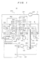
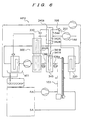
- FIG. 1 is a flow diagram of a dehumidifying apparatus 21 according to a first embodiment of the present invention.
- the dehumidifying apparatus 21 circulates regeneration air B to regenerate a desiccant and dehumidifies process air A with use of the desiccant.
- FIG. 2 is a cross-sectional front view of the dehumidifying apparatus 21 shown in FIG. 1.
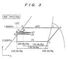
- FIG. 3 is a refrigerant Mollier diagram of a heat pump HP1 included in the dehumidifying apparatus 21 shown in FIG. 1, and
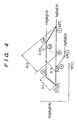
- FIG. 4 is a psychrometric chart of the dehumidifying apparatus 21 shown in FIG. 1.
- the dehumidifying apparatus 21 cools the regeneration air B which has regenerated the desiccant to a temperature equal to or lower than its dew point to condense the moisture in the regeneration air B into water and collect the condensed water, and dehumidifies the process air A with the regenerated desiccant to keep an air-conditioned space 101 which is supplied with the process air A at a low humidity level.
- FIG. 1 devices related to the process air will be described along a path for the process air A from the air-conditioned space 101.
- a path 107 connected to the air-conditioned space 101, an air blower 102 for circulating the process air A, a path 108, a desiccant wheel 103 filled with a desiccant for adsorbing the moisture of the process air A that passes therethrough to lower the humidity of the process air A, and a path 109 are arranged in the order named so as to return the process air A from the path 109 to the air-conditioned space.
- the paths 107 through 109 connect the devices mentioned before the respective paths 107 through 109 to the devices mentioned after the respective paths 107 through 109.
- the desiccant wheel 103 serves as a moisture adsorbing device according to the present invention.
- the paths 124 through 129 connect the devices mentioned before the respective paths 124 through 129 to the devices mentioned after the respective paths 124 through 129.
- the moisture in the regeneration air B which has been condensed by the evaporator 210 is collected by a drain pan 451 disposed vertically below the evaporator 210, and then accumulated in a drain tank 450.
- the paths 201 through 204 connect the devices mentioned before the respective paths 201 through
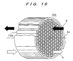
- the desiccant wheel 130 will be described later in detail with reference to FIG. 16.
- the heat exchanger 300 comprises a heat exchanger for performing heat exchange between the regeneration air B flowing into the evaporator 210 and the regeneration air B flowing out of the evaporator 210, indirectly with the refrigerant C.
- the heat exchanger 300 has a plurality of substantially parallel heat exchange tubes as refrigerant paths or tubules in each of a plurality of different planes PA, PB, PC, PD which lie perpendicularly to the sheet of FIG. 1 and also to the flow of the regeneration air B (four planes are illustrated in FIG. 1, but the number of planes is not limited thereto). In FIG. 1, only one tube is shown in each of the above planes for simple illustration.
- the heat exchanger 300 has the first compartment 310 for allowing the regeneration air B before flowing through the evaporator 210 to pass therethrough, and the second compartment 320 for allowing the regeneration air B after flowing through the evaporator 210 to pass therethrough.
- the first compartment 310 and the second compartment 320 form respective separate spaces, each in the form of a rectangular parallelepiped. Both of the compartments have partition walls 301, 302 disposed adjacent to each other, respectively, and the heat exchange tubes extend through these two partition walls 301, 302.
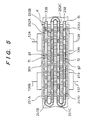
- the heat exchanger 300 may be constructed such that a single space in the form of a rectangular parallelepiped is divided by a single partition wall and the heat exchange tubes as a group of thin pipes extend through the partition wall and alternatively through the first compartment and the second compartment (see FIGS. 5, 12(a) and 12(b)).
- the regeneration air B which has flowed from the desiccant wheel 103 passes from the right in FIG. 1 through the path 126a into the heat exchanger 340, is precooled in the heat exchanger 340, is supplied through the path 126b into the first compartment 310 of the heat exchanger 300, and then flows out of the heat exchanger 300 from the left in FIG. 1 through the path 127.
- the regeneration air B which has passed through the evaporator 210 and has been cooled to a temperature equal to or lower than its dew point with the lowered absolute humidity is supplied from the left in FIG. 1 through the path 129 into the second compartment 320 of the heat exchanger 300, and then flows out of the heat exchanger 300 from the right side of the second compartment 320 of the heat exchanger 300 through the path 124.
- the above heat exchange tubes extend through the first compartment 310, the second compartment 320, and the partition walls 301, 302 which separate those compartments from each other.
- the heat exchange tubes disposed in the plane PA for example, have portions extending through the first compartment 310, and such portions are referred to as an evaporating section 251A (hereinafter simply referred to as an evaporating section 251 in the case where it is not necessary to discuss a plurality of evaporating sections separately).
- the heat exchange tubes disposed in the plane PA also have portions extending through the second compartment 320, and such portions are referred to as a condensing section 252A (hereinafter simply referred to as a condensing section 252 in the case where it is not necessary to discuss a plurality of condensing sections separately).
- the evaporating section 251A and the condensing section 252A serve as a pair of first and second compartment extending portions, and constitute refrigerant paths.
- the heat exchange tubes disposed in the plane PB have portions extending through the first compartment 310, and such portions are referred to as an evaporating section 251B.
- the heat exchange tubes disposed in the plane PB also have portions extending through the second compartment 320, and such portions, which constitute a pair of refrigerant paths with the evaporating section 251B, are referred to as a condensing section 252B.
- Refrigerant paths are also provided in each of the planes PC, ⁇ as with the plane PB.
- the evaporating section 251A and the condensing section 252A are paired with each other and formed by a single tube as an integral passage. This feature, together with the fact that the first compartment 310 and the second compartment 320 are positioned adjacent to each other with the two partition walls 301, 302 being interposed therebetween, is effective in making the heat exchanger 300 small and compact as a whole.
- the evaporating sections 251A, 251B, 251C, ⁇ as the first compartment extending portions are successively arranged in the order named from the right in FIG. 1, and the condensing sections 252A, 252B, 252C, ⁇ as the second compartment extending portions are also successively arranged in the order named from the right in FIG. 1.
- the end of the evaporating section 251A (remote from the partition wall 301) and the end of the evaporating section 251B (remote from the partition wall 301) are connected to each other by a U tube.
- the end of the condensing section 252B and the end of the condensing section 252C are similarly connected to each other by a U tube.
- the refrigerant C flowing in one direction from the condensing section 252A through the evaporating section 251A is introduced into the evaporating section 251B via the U tube, and then flows into the condensing section 252B, from which the refrigerant flows into the condensing section 252C via the U tube.
- the refrigerant paths including the evaporating sections and the condensing sections extend alternately repetitively through the first compartment 310 and the second compartment 320.
- the refrigerant paths are provided as a group of meandering thin pipes.
- a group of meandering thin pipes pass through the first compartment 310 and the second compartment 320, and are held in alternate contact with the regeneration air B which has a higher temperature and the regeneration air B which has a lower temperature.
- the refrigerant from the restriction 330 is first introduced into the condensing section 252A in the present embodiment, the refrigerant may first be introduced into the evaporating section 251A.
- the end of the condensing section 252A (remote from the partition wall 302) and the end of the condensing section 252B (remote from the partition wall 302) are connected to each other by a U tube, and the end of the evaporating section 251B and the end of the evaporating section 251C are similarly connected to each other by a U tube.
- a refrigerant vapor C compressed by the refrigerant compressor 260 is introduced into the refrigerant condenser 220 via the refrigerant vapor pipe 202 connected to the discharge port of the compressor 260.
- the refrigerant vapor C compressed by the compressor 260 is cooled and condensed by the regeneration air B as cooling air immediately before flowing into the desiccant wheel 103, to thus heat the regeneration air B.
- the condenser 220 has a refrigerant outlet connected by the refrigerant passage 203 to the inlet of the condensing section 252A in the heat exchanger 300.
- the restriction 330 is disposed on the refrigerant path 203 near the inlet of the condensing section 252A.
- the refrigerant liquid C that flows out of the condenser 220 is depressurized by the restriction 330 and expanded so as to be partly evaporated (flashed).
- the refrigerant C which is a mixture of the liquid and the vapor reaches the condensing section 252A, where the refrigerant liquid C flows so as to wet the inner wall surface of the tube in the condensing section 252A.
- the flushed refrigerant is cooled and condensed by the cooled regeneration air B immediately after it has flowed out of the evaporator 210.
- the regeneration air B flowing through the second compartment 320 i.e., the regeneration air B which has been cooled and dehumidified by the evaporator 210 to a temperature lower than the temperature of the regeneration air before flowing into the evaporator 210, is heated (preheated).
- the condensing section 252A and the evaporating section 251A are constructed as a continuous tube. Specifically, since the condensing section 252A and the evaporating section 251A are provided as an integral passage, the condensed refrigerant liquid C (and the refrigerant liquid C which has not been condensed) flows into the evaporating section 251A. The refrigerant C is then heated and evaporated by the regeneration air B which has flowed out of the desiccant wheel 103 and has been cooled to a certain extent in the heat exchanger 340, thus further cooling (precooling) the regeneration air B flowing through the first compartment 310. This regeneration air B is the regeneration air B before flowing into the evaporator 210.
- the heat exchanger 300 has the evaporating section as the refrigerant path extending through the first compartment 310 and the condensing section as the refrigerant path extending through the second compartment 320 (at least one pair of them, e.g., denoted by 251A and 252A) in the first plane PA, and also has the condensing section as the refrigerant path extending through the second compartment 320 and the evaporating section as the refrigerant path extending through the first compartment 310 (at least one pair of them, e.g., denoted by 252B and 251B) in the second plane PB.
- the outlet of the final condensing section 252D in the heat exchanger 300 is connected to the evaporator 210 via the refrigerant liquid pipe 204, and the expansion valve 250 is disposed as a restriction on the refrigerant pipe 204.
- the refrigerant liquid C condensed in the condensing section 252 is depressurized and expanded by the restriction 250 to lower its temperature. Then, the refrigerant liquid enters the refrigerant evaporator 210 and is evaporated to cool the regeneration air B with heat of evaporation.
- the restrictions 330, 250 may comprise orifices, capillary tubes, expansion valves, or the like.
- the refrigerant C which has been evaporated into a vapor in the evaporator 210 is introduced into the suction side of the refrigerant compressor 260 through the path 201, and thus the above cycle is repeated.
- the heat pump HP1 pumps heat from low-temperature regeneration air as a low-temperature heat source to high-temperature regeneration air as a high-temperature heat source.
- the dehumidifying apparatus 21 simultaneously regenerates the desiccant and removes moisture from the regeneration air, with the heat pump HP1, and preheats the regeneration air B before regenerating the desiccant and precools the regeneration air B after regenerating the desiccant, with the internal operating medium. Therefore, the dehumidifying apparatus 21 is simple in structure, and has a high moisture removal as most of the cooling effect of the heat pump can be used to condense the moisture in the air.
- the air-to-air heat exchanger 300 is provided across the evaporator 210 to precool and reheat (preheat) the regeneration air B, thereby reducing the sensible heat factor and reducing the amount of cooling down to the dew point.
- the dehumidifying apparatus 21 can recover the heat to cool to the dew point for use as the heat to heat the regeneration air. Therefore, the desiccant can perform the moisture removal with a small amount of electric power. Since the amount of heat required is smaller than the amount of heat needed by a conventional electric heater, and the heat pump HP1 has a high energy efficiency, the electric power consumption of the dehumidifying apparatus is small.
- the cabinet 700 comprises a housing of thin steel sheets in the form of a rectangular parallelepiped, and is divided into an upper region 700A and a lower region 700B which are located vertically with respect to each other and sealed from each other, by a horizontal flat partition plate 701.
- the upper region 700A defines a process air chamber 702 through which the process air A flows from the left-hand end to the right-hand end thereof.
- the lower region 700B primarily defines a regeneration air chamber 703 in which the regeneration air B is circulated as described later.
- the lower region 700B includes a space positioned away from the regeneration air chamber 703 for housing the compressor 260 and the drain tank 450.
- the partition plate 701 may comprise a thin steel sheet which is similar to those of the cabinet 700.
- An air inlet port 104 is opened in a vertically uppermost portion of a left side panel 704A of the cabinet 700, for drawing the process air A from the air-conditioned space 101 (see FIG. 1).
- the air inlet port 104 is an opening of the process air chamber 702, so that the process air A drawn from the air inlet port 104 flows through the process air chamber 702.
- a filter 501 is provided near the air inlet port 104 of the process air chamber 702 for preventing dust in the air-conditioned space 101 from entering the dehumidifying apparatus.
- the air blower 102 is disposed inwardly of the filter 501, and the process air A flowing from the air inlet port 104 through the filter 501 into the process air chamber 702 is drawn by the air blower 102.
- the path 107 is defined between the air inlet port 104 and the air blower 102.
- the process air A is caused to flow through the process air chamber 702 by the air blower 102.
- the process air A discharged from the air blower 102 flows through the path 108, flows horizontally into an upper half of the desiccant wheel 103, and is dehumidified by the desiccant of the desiccant wheel 103.
- the process air A which has flowed horizontally from the upper half of the desiccant wheel 103 passes through the path 109, flows out of the process air chamber 702 (i.e., flows out of the cabinet 700) from an outlet port 110 which is opened in an vertically uppermost portion of a right side panel 704B of the cabinet 700, and is returned and supplied to the air-conditioned space 101.
- the desiccant wheel 103 extends through an opening 706 defined in the partition plate 701 with its rotational axis AX being horizontally oriented.
- the desiccant wheel 103 has a semicircular upper half disposed in the process air chamber 702 and a semicircular lower half disposed in the an upper region 703A, described later, of the regeneration air chamber 703.
- An electric motor 105 as an actuator is disposed near the desiccant wheel 103 in the upper region 703A, described later, of the process air chamber 703 with its rotational axis being horizontally oriented.
- the electric motor 105 and the desiccant wheel 103 are operatively connected to each other by a chain 131, which transmits the rotation of the electric motor 105 to the desiccant wheel 103 to rotate the desiccant wheel 103 at a rotational speed ranging from 15 to 20 revolutions per hour. Since the rotational axis AX of the desiccant wheel 103 is oriented horizontally, the cabinet 700 can be constructed in a compact size with its horizontal length being reduced.
- the height of the process air chamber 702 is slightly larger than the radius of the desiccant wheel 103, and the height of the regeneration air chamber 703 is slightly smaller than twice the radius of the desiccant wheel 103.
- the regeneration air chamber 703 has a horizontal flat partition plate 707 disposed therein which is spaced downwardly from the partition plate 701 by a distance slightly larger than the radius of the desiccant wheel 103.
- the partition plate 707 divides the regeneration air chamber 703 into vertically spaced upper and lower regions 703A, 703B.
- the partition plate 707 has openings 705A, 705B defined respectively in its opposite ends, for allowing the regeneration air B to circulate in the upper and lower regions 703A, 703B therethrough.
- a filter 502 is disposed in a right-hand portion of the upper region 703A of the regeneration air chamber 703, for removing dust from the regeneration air B which flows upwardly from the lower region 703B through the right opening 705B and then flows horizontally.
- the condenser 220 having a coiled heat exchange tube is disposed on the left-hand side of the filter 502.
- the regeneration air B which has passed through the filter 502 passes through the condenser 220, and is heated thereby.
- the regeneration air B which has passed through the condenser 220 and the path 125 flows horizontally into the lower half of the desiccant wheel 103, thus regenerating the desiccant.
- External air as another fluid is introduced into the heat exchanger 340 through a duct (not shown).
- a duct for introducing external air into the heat exchanger 340 is not required.
- air in the environment where the cabinet 700 is installed is used directly as a fluid for exchanging heat with the regeneration air.
- the heat exchanger 340 may use cooling water instead of external air.
- a cooling water supply pipe and a return pipe are connected to the heat exchanger 340.
- the heat exchanger 300 extends through an opening 708 defined in the partition plate 707 and is accommodated in the upper and lower regions 703A, 703B of the regeneration air chamber 703.
- the first compartment 310 of the heat exchanger 300 is disposed in the upper region 703A, and the second compartment 320 of the heat exchanger 300 is disposed in the lower region 703B.
- the regeneration air B which has flowed out of the first compartment 310 of the heat exchanger 300 is drawn through the path 127 into the air blower 140' which circulates the regeneration air B in the regeneration air chamber 703.
- the regeneration air B discharged from the air blower 140 passes through the path 128 which is extremely short and the evaporator 210 having a coiled heat exchange tube, and is cooled by the evaporator 210. While the regeneration air B is then flowing through the path 129, it changes its direction to a vertically downward direction, and passes through the left opening 705A.
- the regeneration air B which has passed through the opening 705A changes its direction to a horizontal direction, flows horizontally in the lower region 703B of the regeneration air chamber 703, and flows into the second compartment 320 of the heat exchanger 300 where the regeneration air B is preheated.
- the drain tank 450 and the compressor 260 are disposed in a portion of the regeneration air chamber 703 which is horizontally closer to the viewer of FIG. 2.
- the regeneration air B which has flowed out of the second compartment 320 of the heat exchanger 300 flows through the path 124, changes its direction to a vertically upward direction, passes through the right opening 705B, then changes its direction to a horizontal direction, and reaches the filter 502. Thereafter, the regeneration air B circulates repeatedly through the above flows.
- the arrangement of devices constituting the heat pump HP1 through which the refrigerant C flows will be described below.
- the compressor 260 and the drain tank 450 are disposed beneath the partition plate 707 away from the lower region 703B of the regeneration air chamber 703.
- the compressor 260 is disposed substantially directly beneath the desiccant wheel 103 as viewed from the viewer of FIG. 2, and the drain tank 450 is disposed substantially directly beneath the evaporator 210.
- the paths 201 through 204 are disposed to connect the devices as shown in FIG. 1.
- the devices are arranged such that the process air A flows horizontally, and the regeneration air B flows mainly horizontally and slightly vertically for circulation.
- the devices may be arranged such that the process air A flows vertically, and the regeneration air B flows mainly vertically and slightly horizontally for circulation.
- FIG. 3 is a Mollier diagram in the case where HFC134a is used as the refrigerant C.
- FIG. 1 will be referred to for the description of the devices.
- the horizontal axis represents the enthalpy h (kJ/kg), and the vertical axis represents the pressure p (MPa).
- HFC407C and HFC410A are suitable refrigerants for the heat pump and the dehumidifying air-conditioning apparatus 21 (see FIG. 1) according to the present invention. These refrigerants have an operating pressure region shifted toward a higher pressure side than HFC134a.
- a point "a" represents a state of the refrigerant at the outlet port of the evaporator 210 shown in FIG. 1, and the refrigerant is in the form of a saturated vapor.
- the refrigerant has a pressure of 0.30 MPa, a temperature of 1°C, and an enthalpy of 399.2 kJ/kg.
- a point b represents a state of the vapor drawn and compressed by the compressor 260, i.e., a state at the outlet port of the compressor 260. In the point b, the refrigerant has a pressure of 1.89 MPa and is in the form of a superheated vapor.
- the refrigerant vapor C is cooled in the condenser 220 and reaches a state represented by a point c in the Mollier diagram.
- the refrigerant is in the form of a saturated vapor and has a pressure of 1.89 MPa and a temperature of 65°C. Under this pressure, the refrigerant is cooled and condensed to reach a state represented by a point d.
- the refrigerant is in the form of a saturated liquid and has the same pressure and temperature as those in the point c.
- the saturated liquid has an enthalpy of 295.8 kJ/kg.
- the refrigerant liquid C is depressurized by the restriction 330 and flows into the condensing section 252A in the heat exchanger 300. This state is indicated at a point e on the Mollier diagram.
- the pressure of the refrigerant liquid is an intermediate pressure according to the present invention, i.e., is of an intermediate value between 0.30 MPa and 1.89 MPa in the present embodiment.
- the intermediate pressure is a saturated pressure at a temperature of 15°C in the present embodiment.
- the refrigerant liquid is a mixture of the liquid and the vapor because part of the liquid is evaporated.
- the refrigerant liquid C is condensed under the intermediate pressure, and reaches a state represented by a point f1 on the saturated liquid curve under the intermediate pressure.
- the refrigerant C in the state represented by the point f1 flows into the evaporating section 251A.
- the refrigerant C removes heat from the regeneration air B having a relatively high temperature and flowing through the first compartment 310, and is evaporated.
- the refrigerant C further flows into the evaporating section 251B and reaches a state represented by a point g1, which is located intermediately between the saturated liquid curve and the saturated vapor curve. In the point g1, while part of the liquid is evaporated, the refrigerant liquid C remains in a considerable amount.
- the refrigerant C in the state represented by the point g1 flows into the condensing section 252B and then into the condensing section 252C.
- the refrigerant C is cooled in these condensing sections, increases its liquid phase, reaches a state represented by a point f2 on the saturated liquid curve, and then flows into the evaporating section 251C and then into the evaporating section 251D.
- the refrigerant C increases its liquid phase, and then reaches a state represented by a point g2.
- the refrigerant C is condensed in the next condensing section 252D and reaches a state represented by a point f3 on the saturated liquid curve.
- the point f3 is on the saturated liquid curve.
- the refrigerant has a temperature of 15°C and an enthalpy of 220.5 kJ/kg.
- the refrigerant liquid C at the point f3 is depressurized to 0.30 MPa, which is a saturated pressure at a temperature of 1°C, by the restriction 250, and reaches a state represented by a point j.
- the refrigerant C at the point j flows as a mixture of the refrigerant liquid C and the vapor at a temperature of 1°C into the evaporator 210, where the refrigerant removes heat from the process air A and is evaporated into a saturated vapor at the state indicated by the point a on the Mollier diagram.
- the evaporated vapor is drawn again by the compressor 260, and thus the above cycle is repeated.
- the dehumidifying apparatus When the dehumidifying apparatus is arranged such that the refrigerant at the state e is not evaporated in the evaporating section 251 as in the present embodiment but is first condensed in the condensing section 252, the amount of the refrigerant in a vapor phase which passes through the restriction 250 under volume control is reduced because the refrigerant becomes close to a two-phase state. Therefore, a cooling effect is maintained at a high level.
- the refrigerant C goes through changes of the condensed state from the point e to the point f1 or from the point g1 to the point f2 in the condensing section 252, and goes through changes of the evaporated state from the point f1 to the point g1 or from the point f2 to the point g2 in the evaporating section 251. Since the refrigerant transfers heat by way of condensation and evaporation, the rate of heat transfer is very high.
- the heat pump HP1 including the compressor 260, the condenser 220, the restrictions 330, 250, and the evaporator 210
- the amount of vapor that is circulated to the compressor 260 under the same cooling load and the required power can be reduced by 42 %. Consequently, the heat pump HP1 according to the present embodiment can perform the same operation as with a subcooled cycle.
- FIG. 1 will be referred to for structural details.
- the alphabetical letters K, L, P and R represent states of air in various regions, and correspond to the alphabetical letters which are encircled in the flow diagram shown in FIG. 1.
- the psychrometric chart shown in FIG. 4 is also applicable to a dehumidifying apparatus according to second and third embodiments of the present invention which will be described later.
- the process air A (in a state K) from the air-conditioned space 101 is drawn through the process air path 107 into the air blower 102, discharged from the air blower 102, and delivered through the path 108 into the desiccant wheel 103.
- the process air A from which moisture has been desorbed by the desiccant wheel 103 and hence which has been dried has its absolute humidity lowered to 2 g/kgDA and its dry-bulb temperature increased (state L).
- the process air A is then returned through the path 109 to the air-conditioned space 101.
- "DA" in the unit of the absolute humidity stands for Dry Air.
- the regeneration air B (in a state P) having an absolute humidity of 5 g/kgDA and a dry-bulb temperature of 5°C, which has flowed out of the evaporator 210, is delivered through the path 129 into the second compartment 320 of the heat exchanger 300.
- the regeneration air B is heated to a certain extent by the refrigerant C which is condensed in the condensing section 252, to increase its dry-bulb temperature (intermediate between 5°C and 60°C) and to keep its absolute humidity constant (state R).
- This process can be referred to as preheating because the regeneration air B is preliminary heated before being heated by the condenser 220.
- the preheated regeneration air B is introduced through the path 124 into the condenser 220.
- the regeneration air B is heated by the condenser 220 to increase its dry-bulb temperature to 60°C, with constant absolute humidity (state T).
- the regeneration air B is further delivered through the path 125 into the desiccant wheel 103, where the regeneration air B removes heat from the desiccant (not shown in FIG. 1) in the dry elements, thus regenerating the desiccant.
- the regeneration air B itself increases its absolute humidity to 10 g/kgDA, and reduces its dry-bulb temperature due to heat of desorption of moisture from the desiccant (state Ua).
- the regeneration air B which has flowed out of the desiccant wheel 103 is delivered through the path 126a into the heat exchanger 340, where the regeneration air B lowers its dry-bulb temperature with constant absolute humidity (state Ub).
- the regeneration air B which has flowed out of the heat exchanger 340 is delivered through the path 126b into the first compartment 310 of the heat exchanger 300.
- the regeneration air B is cooled to a certain extent by the refrigerant C which is evaporated in the evaporating section 251 to lower its dry-bulb temperature and to keep its absolute humidity constant (state V).
- This process can be referred to as precooling because the regeneration air B is preliminary cooled before being cooled to a temperature equal to or lower than its dew point by the evaporator 210.
- the regeneration air B is drawn through the path 127 by the air blower 140 and discharged into the path 128.
- the discharged regeneration air B is delivered through the path 128 into the evaporator 210, where the regeneration air B is dehumidified and cooled to a temperature equal to or lower than its dew point, for thereby lowering its absolute humidity to 5 g/kgDA and its dry-bulb temperature to 5°C (state P).
- the regeneration air B which has flowed out of the evaporator 210 repeats the same cycle.
- the regeneration air B is precooled by the evaporation of the refrigerant C in the evaporating section 251 and heated by the condensation of the refrigerant C in the condensing section 252.
- the refrigerant C evaporated in the evaporating section 251 is condensed in the condensing section 252.
- the evaporation and condensation of the same refrigerant C causes indirect heat exchange between the regeneration air B before being cooled by the evaporator 210 and the regeneration air B after being cooled by the evaporator 210.
- the amount of heat Q with which the regeneration air B is heated in the second compartment 320 corresponds to heating with use of waste heat
- the amount of heat i with which the regeneration air B is heated by the evaporator 210 corresponds to a cooling effect
- the amount of heat recovered by the heat exchanger 300 as an economizer is represented by H.
- the heat exchanger 340 removes heat from the regeneration air B by the amount of heat Q1 to cool the regeneration air B.
- the regeneration air B Since the regeneration air B is cooled to a certain extent by the heat exchanger 340 and then flows into the heat exchanger 300, the temperature of the regeneration air B flowing into the evaporator 210 is lowered closely to its dew point, for thereby increasing the moisture removal of the heat pump per cooling effect.
- the amount of heat that is discharged as a whole when the moisture in a vapor phase in the air-conditioned space is converted into a liquid phase and stored in the tank 450 and the amount of heat corresponding to the drive power of the compressor 260 can be discharged from the dehumidifying system through the heat exchanger 340 (not shown in FIG. 3).
- the refrigerant C which is reduced in pressure by the restriction 330 and which comprises a mixture of a liquid phase and a vapor phase with the refrigerant liquid being partly expanded flows into the condensing section 252A. While the refrigerant C is flowing through the condensing section 252A, the refrigerant C preheats the regeneration air B, and heat is removed from the refrigerant C itself to reduce the vapor phase of the refrigerant, and then the refrigerant C flows into the evaporating section 251A.
- the refrigerant C cools the regeneration air B having a higher temperature than the regeneration air B in the condensing section 252A, and flows into the next evaporating section 251B while heat is applied to the refrigerant C itself to evaporate the refrigerant C in a liquid phase. While the refrigerant C is flowing through the evaporating section 251B, heat is further applied to the refrigerant C by the regeneration air B having a higher temperature to further evaporate the refrigerant C in a liquid phase. Then, the refrigerant C flows into the next condensing section 252B.
- the refrigerant C changes in phase between the vapor phase and the liquid phase while flowing through the refrigerant path.
- heat is exchanged between the regeneration air B before being cooled by the evaporator 210 and the regeneration air B which has been cooled by the evaporator 210 to lower its absolute humidity.
- the heat exchanger 300 is used as a precooling/preheating heat exchanger, and the operating fluid of the heat exchanger 300 and the operating fluid (i.e., the refrigerant) of the heat pump HP1 are the same. Since the process of charging the refrigerant can be shared by the heat exchanger 300 and the heat pump HP1, the cost of manufacture and the cost of maintenance of the dehumidifying apparatus 21 can be reduced.
- the precooling/preheating heat exchanger can be manufactured as a unitary assembly.
- the heat exchanger can be manufactured by production facilities for producing ordinary air/refrigerant heat exchangers, which have no wick. Accordingly, the heat exchanger can be manufactured at a low cost.
- a second embodiment of the present invention will be described below with reference to FIG. 6.
- the second embodiment differs from the first embodiment in that a heat exchanger 340a is used instead of the heat exchanger 340.
- the heat exchanger 340a has a structure similar to the heat exchanger 340.
- the heat exchanger 340a has evaporating sections 341A, 341B and condensing sections 342A, 342B.
- the evaporating sections 341A, 341B correspond to the evaporating sections 251A, 251B of the heat exchanger 300
- the condensing sections 342A, 342B correspond to the condensing sections 252A, 252B of the heat exchanger 300. While the evaporating sections and the condensing sections are shown as being considerably spaced apart from each other, they should preferably be in the form of a group of integral thin pipes as with the heat exchanger 300.
- the evaporating sections extend through a first compartment 343 and the condensing sections extend through a second compartment 344.
- the first compartment 343 is inserted between the desiccant wheel 103 and the first compartment 310 of the heat exchanger 300.
- the regeneration air B which has passed through the desiccant wheel 103 passes through the first compartment 343 of the heat exchanger 340a, and then flows into the first compartment 310 of the heat exchanger 300.
- the second compartment 344 of the heat exchanger 340a is arranged such that external air is allowed to pass therethrough by an air blower 144.
- the refrigerant pipe 203 extending into the condensing section 342A has a restriction 336 disposed thereon.
- the dehumidifying apparatus is arranged such that the heat exchanger 340a is inserted on the refrigerant pipe 203 according to the first embodiment as viewed along the flow of the refrigerant.
- the refrigerant C flows through the condensing section 342A, the evaporating section 341A, the evaporating section 341B, and the condensing section 342B, and then reaches the restriction 330. In this time, heat is transferred from the regeneration air B passing through the first compartment 343 to external air passing through the second compartment 344 by the condensation and evaporation of the refrigerant, as with the heat exchanger 300.
- FIG. 7 is a Mollier diagram plotted in the case where FC134a is used as the refrigerant C, as with FIG. 3. Details of operation which are the same as those described with reference to FIG. 3 will not be described below.
- points a, b, c, d are the same as those shown in FIG. 3.
- the refrigerant liquid C in the state represented by the point d is reduced in pressure by the restriction 336 and flows into the condensing section 342A of the heat exchanger 340a. This state is indicated by a point "e" on the Mollier diagram.
- the pressure of the refrigerant is an intermediate pressure according to the present invention, and is of an intermediate value between 0.30 MPa and 1.89 MPa in the present embodiment.
- the intermediate pressure is higher to a certain extent than a saturated pressure at a temperature of 13°C.
- the refrigerant C is a mixture of the liquid and the vapor because part of the liquid is evaporated.
- the refrigerant C is condensed under the intermediate pressure, and reaches a state represented by a point f1 on a saturated liquid curve under the intermediate pressure.
- the refrigerant C in the state indicated by the point f1 flows into the evaporating section 341A.
- the refrigerant C removes heat from the regeneration air B having a relatively high temperature and flowing through the first compartment 343, and is evaporated.
- the refrigerant C further flows into the evaporating section 341B, and reaches a state represented by a point g1, which is located intermediately between the saturated liquid curve and the saturated vapor curve. In the point g1, while part of the liquid is evaporated, the refrigerant liquid C remains in a considerable amount.
- the refrigerant C in the state represented by the point g1 flows into the condensing section 342B, is cooled to increase its liquid phase, and reaches a state represented by a point f2 on the saturated liquid curve.
- the refrigerant liquid C is reduced in pressure by the restriction 330, and flows into the condensing section 252A of the heat exchanger 300. Subsequent operation is the same as the operation described above with reference to FIG. 3, and will not be described below.
- the points f1, g1, f2, g2, f3 shown in FIG. 3 are changed respectively to points f3, g3, f4, g4, f5 in FIG. 7.
- the operating temperature of the heat exchanger 300 is lowered to a certain extent from 15°C to 13°C because the refrigerant C is efficiently cooled by the heat exchanger 340a.
- the heat pump since the heat pump has the heat exchanger 304a which utilizes heat transfer by way of condensation and evaporation, the regeneration air B can be cooled with an excellent rate of heat transfer. The cooling effect of the refrigerant can further be increased.
- a third embodiment of the present invention will be described below with reference to FIGS. 8 and 9.
- the third embodiment differs from the first embodiment shown in FIG. 1 in that the refrigerant flows from the restriction 330 first into the evaporating section 251A of a heat exchanger 300b, the refrigerant moves from the plane PA to the plane PB between the condensing sections 252A, 252B (the movement of the refrigerant between the other planes is successively shifted), a plane PE is added, and restrictions 331, 332 are provided between the evaporating sections in the planes PB, PC and between the evaporating sections in the planes PD, PE.
- FIG. 1 differs from the first embodiment shown in FIG. 1 in that the refrigerant flows from the restriction 330 first into the evaporating section 251A of a heat exchanger 300b, the refrigerant moves from the plane PA to the plane PB between the condensing sections 252A, 252B (the movement of the refrigerant between the
- the major change of the third embodiment from the first embodiment is the restrictions 331, 332 disposed between the planes.
- Other changes do not cause a significant operational change except that the evaporation and condensation in the heat exchanger 300b are shifted as a whole to a vapor phase because the refrigerant flows from the restriction 330 first into the evaporating section 251A.
- More planes than the planes PA through PE may be added, and more restrictions may be added accordingly.
- the refrigerant C introduced into the evaporating section 251A is partly evaporated into a two-phase state in the evaporating section 251A, and flows into the condensing section 252A.
- the refrigerant changes its direction in the U tube, and flows into the condensing section 252B and the evaporating section 251B.
- the refrigerant is partly evaporated in the evaporating section 251B, is depressurized by the restriction 331, and flows into the evaporating section 251C in the plane PC.
- the refrigerant is further evaporated in the evaporating section 251C, and then flows into the condensing section 252C.
- the refrigerant changes its direction in the U tube, and flows into the condensing section 252D.
- the refrigerant is further condensed and then flows into the evaporating section 251D.
- the refrigerant C is partly evaporated in the evaporating section 251D, and reaches the restriction 332.
- the refrigerant is depressurized by the restriction 332, and flows into the evaporating section 251E in the plane PE and subsequently into the condensing section 252E in the plane PE.
- the refrigerant C is sufficiently condensed in the condensing section 252E, and flows through the path 204 to the expansion valve 250.
- the evaporating pressures in the evaporating sections 251A, 251B and the condensing pressures in the condensing sections 252A, 252B, i.e., first intermediate pressures, or the pressures in the evaporating sections 251C, 251D and the condensing sections 252C, 252D, i.e., second intermediate pressures, depend on the temperature of the regeneration air B before flowing into the evaporator 210 and the temperature of the regeneration air B after flowing through the evaporator 210 and being cooled therein.
- the heat exchanger 300 shown in FIG. 1 or the heat exchanger 300b shown in FIG. 8 utilizes heat transfer by way of evaporation and condensation, the heat exchanger has an excellent rate of heat transfer.
- the heat exchanger 300b has a very high efficiency of heat exchange as it performs heat exchange of the regeneration air B on the counterflow principles as described later. Since the refrigerant C is forcibly caused to flow in a substantially one direction as a whole in the refrigerant paths, from the evaporating section 251 to the condensing section 252 or from the condensing section 252 to the evaporating section 251, the efficiency of heat exchange between the regeneration air B having a high temperature and the regeneration air B having a low temperature is very high.
- the refrigerant flows in a substantially one direction as a whole means that the refrigerant C flows in a substantially one direction in the refrigerant paths when viewed as a whole even though the refrigerant may locally flow back due to turbulences or be vibrated in the flowing direction due to pressure waves produced by bubbles or instantaneous interruptions.
- the refrigerant C is forced to flow in one direction under the pressure increased by the compressor 260.
- FIG. 8 shows only part of components of the heat pump HP3, and FIG. 1 will be referred to for other components.
- FIG. 9 the transitions from the point a to the point e are identical to the first embodiment shown in FIG. 3 and will not be described below.
- the refrigerant C in the state represented by the point e which flows into the evaporating section 251A in the heat exchanger 300b is a mixture of the liquid and the vapor with part of the liquid being evaporated under the first intermediate pressure, as described above with reference to FIG. 3.
- the refrigerant C is further evaporated in the evaporating section 251A, and reaches a point f1 nearer to the saturated vapor curve in the two-phase region on the Mollier diagram.
- the refrigerant C in this state flows into the condensing section 252A, where the refrigerant is condensed.
- refrigerant is reversed in direction by the U tube, flows into the condensing section 252B, is further condensed, and reaches a point g1 nearer to the saturated liquid curve though in the two-phase region.
- the refrigerant flows into the evaporating section 251B, goes toward the saturated vapor curve within the two-phase region to reach a point h1a. Up to this point, the refrigerant undergoes changes substantially under the first intermediate pressure.
- the refrigerant C in the state represented by the point h1a is depressurized by the restriction 331, and reaches a point h1b under the second intermediate pressure.
- the refrigerant flows from the evaporating section 251B as the refrigerant path in the plane PB through the restriction 331 into the evaporating section 251C as the refrigerant path in the plane PC.
- This refrigerant C is evaporated under the second intermediate pressure in the evaporating section 251C, and reaches a point f2.
- the refrigerant is then repeatedly similarly evaporated into a vapor phase and condensed into a liquid phase alternately, and depressurized by the intermediate restriction 332 to a third intermediate pressure.
- the refrigerant C which flows through the refrigerant paths of the evaporating section 251E and the condensing section 252E reaches a point g3 on the Mollier diagram which corresponds to the point f3 in FIG. 3.
- the point g3 is on the saturated liquid curve.
- the refrigerant has a temperature of 11°C and an enthalpy of 215.0 kJ/kg.
- the refrigerant liquid C at the point g3 is depressurized to 0.30 MPa, which is a saturated pressure at a temperature of 1°C, by the restriction 250, and reaches a state represented by a point j.
- the refrigerant flows as a mixture of the refrigerant liquid C and the vapor at a temperature of 1°C into the evaporator 210, where the refrigerant removes heat from the regeneration air B and evaporated into a saturated vapor at the state indicated by the point a on the Mollier diagram.
- the evaporated vapor is drawn again by the compressor 260, and thus the above cycle is repeated.
- the refrigerant C repeatedly goes alternately through changes of vapor phase and changes of liquid phase. Since the refrigerant transfers heat by way of evaporation and condensation, the rate of heat transfer is very high, as with the heat exchanger 300 in the first embodiment.
- the regeneration air B before being cooled in the evaporator 210 exchanges heat successively in the evaporating sections 251A, 251B, 251C, 251D, 251E in the first compartment 310. Specifically, the temperature gradient of the regeneration air B and the temperature gradient of the evaporating section 251 are in the same direction. Similarly, the regeneration air B after being cooled in the evaporator 210 exchanges heat successively in the condensing sections 252E, 252D, 252C, 252B, 252A in the second compartment 320. Specifically, the temperature gradient of the regeneration air B and the temperature gradient of the condensing section 252 are in the same direction.
- heat exchange is performed between the counterflows of the regeneration air B before being cooled in the evaporator 210 and the regeneration air B after being cooled in the evaporator 210.
- Such heat exchange together with the heat transfer by way of evaporation and condensation, allows the heat exchanger 300b to achieve a very high efficiency of heat exchange.
- the enthalpy difference that can be used by the evaporator 210 is remarkably larger than that in the conventional heat pump.
- FIG. 10 shows a flow diagram of a dehumidifying apparatus 23 according to a fourth embodiment of the present invention.
- a heat exchanger 300c which corresponds to the heat exchanger 300 according to the first embodiment and the heat exchanger 300b according to the second embodiment, has restrictions 331, 332 disposed at the condensing section 252 side.
- Other structural details of the fourth embodiment are identical to those of the second embodiment shown in FIG. 8.
- FIG. 11 is a Mollier diagram of a heat pump HP4 shown in FIG. 10.
- the refrigerant is depressurized in the condensing process under the intermediate pressure.
- the refrigerant is depressurized from a point g1a to a point g1b by the restriction 331 and depressurized from a point g2a to a point g2b by the restriction 332.
- the fourth embodiment is also the same as the embodiment shown in FIG. 9 in that heat exchange is performed between the counterflows of the regeneration air B before being cooled in the evaporator 210 and the regeneration air B after being cooled in the evaporator 210.
- the restrictions may be provided as a combination of the restrictions shown in FIGS. 8 and 10, and disposed on both sides of the evaporating sections and the condensing sections.
- a drain pan 451 is shown in FIGS. 1 and 6, and such a drain pan is preferably located below not only the evaporator 210, but also the heat exchangers 300, 300b, 300c. Particularly, the drain pan 451 is preferably disposed below the first compartment 310 because the regeneration air B is mainly precooled in the first compartment 310 of the heat exchangers 300, 300b, 300c and some moisture may possibly be condensed therein.
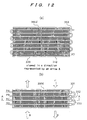
- FIG. 12 (a) is a drawing showing the heat exchanger as viewed in the direction in which the regeneration air B having a low temperature and the regeneration air B having a high temperature are flowing
- FIG. 12(b) is a drawing of side elevational view showing the heat exchanger as viewed in a direction perpendicular to the flows of the low-temperature regeneration air and the high-temperature regeneration air.
- FIG. 12(a) is a view as viewed from an arrow taken along a line A-A of FIG. 12(b).
- FIG. 12 (a) is a drawing showing the heat exchanger as viewed in the direction in which the regeneration air B having a low temperature and the regeneration air B having a high temperature are flowing
- FIG. 12(b) is a drawing of side elevational view showing the heat exchanger as viewed in a direction perpendicular to the flows of the low-temperature regeneration air and the high-temperature regeneration air.
- FIG. 12(a) is a view as viewed from an arrow taken along a line
- the high-temperature regeneration air B flows through the compartment 310 away from the viewer, and the low-temperature regeneration air B through the compartment 320 toward the viewer.
- tubes are disposed in eight rows in each of the four planes PA, PB, PC, PD which lie perpendicularly to the flows of the low-temperature regeneration air B and the high-temperature regeneration air B.
- the tubes are arranged in four tiers and eight rows along the flows of the regeneration air B.
- a plane PE not shown, may be provided below the plane PD, and eight rows of tubes may be disposed in the plane PE.
- the heat exchange tube is disposed in one row per tier in each of the planes PA, PB, PC and PD for illustrative purpose.
- the tubes are provided in a plurality of rows per tier. In this manner, the tubes constitute a group of thin pipes.
- An intermediate restriction 331 is disposed in a transitional location from the first plane PA to the next plane PB.
- An intermediate restriction 332 (not shown) is disposed in a transitional location from the plane PB to the plane PC.
- An intermediate restriction 333 is disposed in a transitional location from the plane PC to the plane PD. While one restriction is provided in a transitional location from one plane to the next, tube rows in the plane PA may be arranged in a plurality of layers. In such an arrangement, an intermediate restriction is disposed in a transitional location from each layer to the next. Planes prior and subsequent to an intermediate restriction are referred to as first and second planes.
- Heat exchangers each having tubes in eight rows and four layers (tiers) as shown in FIGS. 12(a) and 12(b) may be arranged parallel to each other or in series with each other with respect to the flows of the high- and low-temperature regeneration air, depending on the amount of the regeneration air.
- the cycle is effective even if the refrigerant C is repeatedly evaporated and condensed into a subcooled region beyond the saturated liquid curve.
- the refrigerant C should preferably change its phase in the two-phase region.
- the heat transfer area of the first evaporating section connected to the restriction 330 should preferably be larger than the heat transfer area of the succeeding evaporating section.
- the heat transfer area of the condensing section connected to the restriction 250 should preferably be larger than the heat transfer area of the prior condensing section.
- the heat exchanger according to the present invention is inexpensive and economical when being used instead of expensive heat pipes. Unlike heat pipes, the heat exchanger according to the present invention can be maintained with little effort because it can use the same operating fluid as in the heat pump.
- FIG. 13 is a flow diagram showing flows in the dehumidifying apparatus according to the fifth embodiment
- FIG. 14 is a Mollier diagram of the refrigerant in a heat pump HP5 included in the dehumidifying apparatus shown in FIG. 13.
- FIG. 13 a heat exchanger 300e and refrigerant and air paths connected thereto are shown, and other details are omitted from illustration.
- the fifth embodiment differs from the third embodiment shown in FIG. 8 in that the heat exchanger 300b according to the third embodiment shown in FIG. 8 is replaced with the heat exchanger 300e.
- Those parts or elements of the fifth embodiment which operates in the same manner or has the same functions as those of the third embodiment are denoted by the identical reference characters, and those parts or elements of the fifth embodiment which will not be described below are the same as those of the third embodiment.
- the refrigerant path is branched into a plurality of paths (three paths in FIG. 13) downstream of the condenser 220, i.e., branched refrigerant paths 51 through 53, unlike the other embodiments.
- the branched refrigerant paths 51 through 53 are joined into a single refrigerant path 204 upstream of the evaporator 210.
- a plurality of branched refrigerant paths are provided between the condenser 220 and the evaporator 210, and a first heat exchanging means and a second heat exchanging means are disposed in the branched refrigerant paths.
- the dehumidifying apparatus has a plurality of thin pipe groups 51 (52, 53) connected to the condenser 220 through first restrictions 331a (332a, 333a) and alternatively extending through the first compartment 310 and the second compartment 320 repeatedly and then connected to the evaporator 210 through corresponding second restrictions 331b (332b, 333c), and a plurality of combinations of the first restrictions 331a, 332a, 333a and the second restrictions 331b, 332b, 333c which correspond respectively to the thin pipe groups 51, 52, 53.
- the branched refrigerant paths 51 through 53 alternately extend through a first heat exchanging portion (first compartment) 310 and a second heat exchanging portion (second compartment) 320 of the heat exchanger 300e repeatedly.
- the branched refrigerant paths 51 through 53 have the restrictions 331a through 333a upstream of the first heat exchanging portion 310 and the restrictions 331b through 333b downstream of the second heat exchanging portion 320.
- These restrictions 331a through 333b may comprise orifices, capillary tubes, expansion valves, or the like, for example.
- the first compartment 310 and the second compartment 320 are arranged such that the regeneration air flows as counterflows in the respective compartments 310, 320.
- the refrigerant paths 51, 52, 53 are arranged in the order named in the downstream direction of the regeneration air.
- the refrigerant paths 51, 52, 53 are arranged in the order named in the upstream direction of the regeneration air.
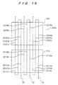
- FIG. 15 is an enlarged view showing the branched refrigerant paths 51 through 53 in the heat exchanger 300e in the dehumidifying apparatus shown in FIG. 13.
- the branched refrigerant paths 51 through 53 extend through the first heat exchanging portion 310 and the second heat exchanging portion 320.
- the branched refrigerant path 51 has an evaporating section 251Aa, a condensing section 252Aa, a condensing section 252Ab, an evaporating section 251Ab, an evaporating section 251Ac, and a condensing section 252Ac arranged successively from the condenser 220.
- the branched refrigerant path 52 has an evaporating section 251Ba, a condensing section 252Ba, a condensing section 252Bb, an evaporating section 251Bb, an evaporating section 251Bc, and a condensing section 252Bc
- the branched refrigerant path 53 has an evaporating section 251Ca, a condensing section 252Ca, a condensing section 252Cb, an evaporating section 251Cb, an evaporating section 251Cc, and a condensing section 252Cc.
- the behavior of the refrigerant from the point a to the point d is the same as the behavior of the refrigerant in the third embodiment shown in FIG. 9, and will not be described below.
- the refrigerant liquid which has been cooled in the condenser 220 and has reached the state represented by the point d is branched into the branched refrigerant paths 51 through 53 and flows into the heat exchanger 300e.
- the refrigerant flowing through the refrigerant path 52 will be described below.
- the refrigerant liquid flowing into the refrigerant path 52 is depressurized by the restriction 332a and flows into the evaporating section 251Ba of the first heat exchanger 310.
- the refrigerant is a mixture of the liquid and the vapor because part of the liquid is evaporated.
- the pressure of the refrigerant is an intermediate pressure between the condensing pressure in the condenser 220 and the evaporating pressure in the evaporator 210, i.e., is of an intermediate value between 1.89 MPa and 0.30 MPa in the present embodiment.
- the refrigerant liquid is evaporated under the intermediate pressure, and reaches a state represented by at a point f1 which is located intermediately between a saturated liquid curve and a saturated vapor curve, under the intermediate pressure.
- the point f1 while part of the liquid is evaporated, the refrigerant liquid C remains in a considerable amount.
- the refrigerant in the state represented by the point f1 flows into the condensing sections 252Ba, 252Bb.
- the refrigerant in the state represented by the point g1 flows into the evaporating sections 251Bb, 251Bc, where heat is removed from the refrigerant.
- the refrigerant increases its liquid phase and reaches a state represented by a point f2.
- the refrigerant flows into the condensing section 252Bc, where the refrigerant increases its liquid phase and reaches a state represented by a point g2.
- the point g2 is on the saturated liquid curve.
- the refrigerant has a temperature of 11°C and an enthalpy of 215.0 kJ/kg.
- the refrigerant liquid at the point g2 is depressurized to 0.30 MPa, which is a saturated pressure at a temperature of 1°C, by the restriction 332b, and reaches a state represented by a point q.
- the refrigerant at the point q flows as a mixture of the refrigerant liquid and the vapor at a temperature of 1°C into the evaporator 210, where the refrigerant removes heat from air in the staté at a point V, and is evaporated into a saturated vapor at the state represented by the point a.
- the saturated vapor is drawn again by the pressurizer 260, and thus the above cycle is repeated.
- the refrigerant flowing into the refrigerant path 51 passes through the restriction 331a, the evaporating sections, the condensing sections, and the restriction 331b, goes through states represented by points j, i1, k1, i2, k2, and reaches a state represented by a point 1.
- the refrigerant flowing through the refrigerant path 53 passes through the restriction 333a, the evaporating sections, the condensing sections, and the restriction 333b, goes through states represented by points m, n1, o1, n2, o2, and reaches a state represented by a point r.
- the refrigerant goes through changes of the evaporated state from the point e to the point f1 or from the point g1 to the point f2 in the evaporating sections, and goes through changes of the condensed state from the point f1 to the point g1 or from the point f2 to the point g2 in the condensing sections. Since the refrigerant transfers heat by way of evaporation and condensation, the rate of heat transfer is very high and the efficiency of heat exchanger is high.
- the heat exchanger 300e in the vapor compression type heat pump HP5 including the pressurizer 260, the condenser 220, the restrictions 331a through 333b, and the evaporator 210 (other details than the heat exchanger 300e and the refrigerant and air paths are omitted from illustration in FIG. 13), when the heat exchanger 300e according to the present invention is provided, the amount of vapor that is circulated to the pressurizer under the same cooling load and the required power can remarkably be reduced as with the third embodiment. Thus, the heat pump can perform the same operation as with a subcooled cycle.
- the dehumidifying apparatus since the enthalpy of the refrigerant at the inlet of the evaporator 210 is reduced due to the economizer effect of the heat pump HP5 and the cooling effect of the refrigerant per unit flow rate is high, the moisture removal effect and the energy efficiency are increased.
- the present invention is not limited to the above embodiments, but may be carried out in various different forms with the scope of the technical ideas thereof.
- the number of evaporating sections in the first heat exchanging portions in the refrigerant paths and the number of condensing sections in the second heat exchanging portions in the refrigerant paths are not limited to the illustrated examples.
- the number of the branched refrigerant paths in the fifth embodiment is not limited to the illustrated example, but the refrigerant path may be branched into any number of branched refrigerant paths.
- the desiccant wheel 103 comprises a thick disk-shaped wheel which is rotatable about a rotational axis AX, and a desiccant is filled into the wheel with gaps for allowing a gas to pass therethrough.
- the desiccant wheel 103 comprises a number of tubular dry elements bounded to each other so that their central axes extend parallel to the rotational axis AX.
- the wheel is arranged so as to rotate in one direction about the rotational axis AX and also to allow the process air A and the regeneration air B to flow into and out of the desiccant wheel 103 parallel to the rotational axis AX.
- Each of the dry elements is positioned so as to alternately contact the process air A and the regeneration air B according to rotation of the desiccant wheel 103.
- the desiccant wheel 103 is arranged so that the process air A and the regeneration air B flow as counterflows parallel to the rotational axis AX through respective substantially half areas of the circular desiccant wheel 103.
- the region through which the process air A flows and the region through which the regeneration air B flows are separated from each other by a partition plate (not shown in FIG. 16).
- the desiccant wheel 103 rotates across the partition plate to bring the dry elements 103a into alternate contact with the process air A and the regeneration air B.
- the wheel is shown as being partly cut away to illustrate the dry elements 103a clearly.
- the desiccant may be filled in the tubular dry elements as described above.
- the desiccant wheel 103 is arranged to allow the process air A and the regeneration air B to flow across the disk-shaped rotor.
- the same refrigerant C is used as a heat transfer medium in the evaporator 210 for cooling the regeneration air B to a temperature equal to or lower than its dew point, the first compartment 310 of the heat exchangers 300, 300b, 300c, 300d, 300e for precooling the regeneration air B, the condenser 220 for heating the regeneration air B, and the second compartment 320 of the heat exchangers 300, 300b, 300c, 300d, 300e for preheating the regeneration air B. Therefore, the refrigerant system is simplified.
- the refrigerant is positively circulated because the pressure difference between the evaporator 210 and the condenser 220 can be utilized. Since a boiling phenomenon with a phase change is applied to heat exchanges for precooling and preheating the process air, a high efficiency can be achieved.
- the dehumidifying apparatus according to the above embodiments has been described as the dehumidifying apparatus for dehumidifying an air-conditioned space.
- the dehumidifying apparatus according to the present invention is applicable not only to the air-conditioned space, but also to other spaces that need to be dehumidified.
- a dehumidifying apparatus comprises a moisture adsorbing device for removing moisture from process air and for being regenerated by desorbing moisture therefrom with regeneration air; and a heat pump having a condenser for condensing a refrigerant to heat said regeneration air at the upstream side of said moisture adsorbing device, an evaporator for evaporating said refrigerant to cool said regeneration air to a temperature equal to or lower than its dew point at the downstream side of said moisture adsorbing device, a pressurizer for raising a pressure of said refrigerant evaporated by said evaporator and delivering said refrigerant to said condenser, and a first heat exchanger for exchanging heat between said regeneration air flowing between said moisture adsorbing device and said evaporator and the regeneration air flowing between said evaporator and said condenser; wherein said regeneration air is used in circulation.
- the regeneration air can be precooled by the heat exchanging means prior to cooling in the evaporator, and the amount of heat removed in the precooling process can be recovered from the regeneration air which has been cooled by the evaporator.
- a dehumidifying apparatus having a heat pump with a high coefficient of performance can be provided, and it is possible to provide a dehumidifying apparatus which consumes a small amount of energy per amount of moisture removal.
- the moisture of the process air is not removed by being cooled by the evaporator, but is removed by the moisture adsorbing device. Therefore, it is possible to obtain air having a low dew point equal to or lower than an freezing point, i.e., a low absolute humidity of 4 g/kgDA or lower.
Landscapes
- Engineering & Computer Science (AREA)
- Mechanical Engineering (AREA)
- General Engineering & Computer Science (AREA)
- Chemical & Material Sciences (AREA)
- Combustion & Propulsion (AREA)
- Physics & Mathematics (AREA)
- Thermal Sciences (AREA)
- Life Sciences & Earth Sciences (AREA)
- Sustainable Development (AREA)
- Central Air Conditioning (AREA)
- Drying Of Gases (AREA)
Abstract
A dehumidifying apparatus capable of continuously
supplying dry air having an absolute humidity of 4 g/kgDA or
lower is provided. The dehumidifying apparatus has a
moisture adsorbing device for removing moisture from process
air and for being regenerated by desorbing moisture
therefrom with regeneration air B, and a heat pump having a
condenser for condensing a refrigerant to heat the
regeneration air at the upstream side of the moisture
adsorbing device, an evaporator for evaporating the
refrigerant to cool the regeneration air to a température
equal to or lower than its dew point at the downstream side
of the moisture adsorbing device, a pressurizer for raising
a pressure of the refrigerant evaporated by the evaporator
and delivering the refrigerant to the condenser, and a heat
exchanger for exchanging heat between the regeneration air
flowing between the moisture adsorbing device and the
evaporator and the regeneration air flowing between the
evaporator and the condenser, wherein said regeneration air
is used in circulation. Since moisture is removed from the
process air by the moisture adsorbing device, it is possible
to obtain air having a low dew point equal to or lower than
an freezing point, i.e., a low absolute humidity of 4 g/kgDA
or lower.
Description
The present invention relates to a dehumidifying
apparatus, and more particularly to a dehumidifying
apparatus having a high moisture removal.
As shown in FIG. 17, there has heretofore been
available a dehumidifying apparatus 11 having a compressor 1
for compressing a refrigerant C, a condenser 2 for
condensing the compressed refrigerant C to heat process air
A, an evaporator 3 for depressurizing the condensed
refrigerant C with an expansion valve 5 and evaporating the
refrigerant to cool the process air A to a temperature equal
to or lower than its dew point. The evaporator 3 cools the
process air A from an air-conditioned space 10 to a
temperature equal to or lower than its dew point to remove
moisture from the process air A, the condenser 2 heats the
process air A which has been cooled to a temperature equal
to or lower than its dew point, and the heated process air A
is supplied to the air-conditioned space 10. With the
illustrated dehumidifying apparatus 11, a heat pump HP is
constituted by the compressor 1, the condenser 2, the
expansion valve 5, and the evaporator 3. The heat pump HP
pumps heat from the process air A which flows through the
evaporator 3 into the process air A which flows through the
condenser 2.
The conventional dehumidifying apparatus 11
having the heat pump HP cannot supply dry air having an
absolute humidity of 4 g/kgDA or lower. The reason is that
since the operating temperature of the evaporator 3 in the
heat pump HP is equal to or lower than the freezing point,
the removed moisture is deposited as frost on the heat
transfer surface to inhibit the heat transfer, and hence the
apparatus cannot continuously be operated.
It is therefore an object of the present
invention to provide a dehumidifying apparatus which can
prevent moisture removed from air from being deposited as
frost on a heat transfer surface of an evaporator in a heat
pump to continuously supply dry air having an absolute
humidity of 4 g/kgDA or lower.
To achieve the above object, according to an
aspect of the present invention, as shown in FIG. 1, for
example, there is provided a dehumidifying apparatus
comprising: a moisture adsorbing device 103 for removing
moisture from process air A and for being regenerated by
desorbing moisture therefrom with regeneration air B; and a
heat pump HP1 having a condenser 220 for condensing a
refrigerant C to heat said regeneration air B at the
upstream side of said moisture adsorbing device 103, an
evaporator 210 for evaporating said refrigerant C to cool
said regeneration air B to a temperature equal to or lower
than its dew point at the downstream side of said moisture
adsorbing device 103, a pressurizer 260 for raising a
pressure of said refrigerant C evaporated by said evaporator
210 and delivering said refrigerant C to said condenser 220,
and a first heat exchanger 300 for exchanging heat between
said regeneration air B flowing between said moisture
adsorbing device 103 and said evaporator 210 and the
regeneration air B flowing between said evaporator 210 and
said condenser 220; wherein said regeneration air B is used
in circulation.
With the above arrangement, since the
dehumidifying apparatus has the condenser, the evaporator,
and the first heat exchanger, the regeneration air is
circulated such that it is heated by the condenser,
regenerates the moisture adsorbing device to increase the
amount of moisture contained in the regeneration air, is
cooled by the first heat exchanger, is cooled and condensed
by the evaporator to reduce the amount of moisture contained
in the regeneration air, and is heated by the first heat
exchanger. When the regeneration air is cooled by the first
heat exchanger, the moisture thereof may partly be
condensed, reducing the amount of moisture contained in the
regeneration air. The regeneration air is cooled
(precooled) by the first heat exchanger prior to cooling in
the evaporator, and is heated (preheated) by the heat
exchanger after cooling by the evaporator. Therefore, the
dehumidifying apparatus can be operated at a low sensible
heat factor.
Since the moisture of the process air is adsorbed
by the moisture adsorbing device, the humidity of the
process air is greatly reduced, and hence dry air can be
supplied. The expression that the regeneration air is used
in circulation means that after having regenerated the
moisture adsorbing device, e.g., the desiccant of a
desiccant wheel, the regeneration air flows a circulating
circuit so that most of the regeneration air can be used
again as regeneration air, without being discharged directly
into the atmosphere (no regeneration air may be discharged
into the atmosphere, or part of regeneration air may be
discharged into the atmosphere) .
In the first heat exchanger, the refrigerant is
evaporated and condensed typically under an intermediate
pressure between the condensing pressure in the condenser
and the evaporating pressure in the evaporator.
In the dehumidifying apparatus, the first heat
exchanger 300 may comprise a thin pipe group connecting the
condenser 220 and the evaporator 210 to each other, for
passing the refrigerant therethrough; wherein the thin pipe
group may be arranged so as to introduce the refrigerant
condensed by the condenser 220 to the evaporator 210 and
also to bring said refrigerant into alternate contact with
the regeneration air flowing between the moisture adsorbing
device 103 and the evaporator 210 and the regeneration air
flowing between the evaporator 210 and the condenser 220.
With the above arrangement, since the thin pipe
group into which the refrigerant is introduced is brought
into alternate contact with the regeneration air flowing
between the moisture adsorbing device and the evaporator and
the regeneration air flowing between the evaporator and the
condenser, heat exchange between these two flows of the
regeneration air can be performed by the refrigerant. The
connection between the condenser and the evaporator includes
indirectly connecting the condenser and the evaporator with
a pipe, a pipe joint, or the like.
In the dehumidifying apparatus, as shown in FIG.
1, for example, the first heat exchanger 300 may have a
first compartment 310 for passing the regeneration air
between the moisture adsorbing device 103 and the evaporator
210, and a second compartment 320 for passing the
regeneration air between the evaporator 210 and the
condenser 220, the thin pipe group being connected to the
condenser 220 through a first restriction 330, extending
alternately through the first compartment 310 and the second
compartment 320 repeatedly, and then being connected to the
evaporator 210 through a second restriction 250.
With the above arrangement, since the
dehumidifying apparatus has the first restriction and the
second restriction, while the refrigerant is passing through
the first restriction and the second restriction, the
refrigerant develops a pressure drop across each of the
first restriction and the second restriction. The
refrigerant passing through the first compartment is
evaporated and the refrigerant passing through the second
compartment is condensed under an intermediate pressure
between the condensing pressure of the refrigerant in the
condenser and the evaporating pressure of the refrigerant in
the evaporator. Therefore, the heat exchanger acts as an
economizer, and the coefficient of performance (COP) of the
heat pump is increased.
As shown in FIG. 13, for example, the
dehumidifying apparatus may have a plurality of thin pipe
groups 51 (52, 53) connected to the condenser 220 through
first restrictions 331a (332a, 333a) and alternatively
extending through the first compartment 310 and the second
compartment 320 repeatedly and then connected to the
evaporator 210 through corresponding second restrictions
331b (332b, 333c), and a plurality of combinations of the
first restrictions 331a, 332a, 333a and the second
restrictions 331b, 332b, 333c which correspond respectively
to the thin pipe groups 51, 52, 53. As shown in FIG. 13,
the first compartment 310 and the second compartment 320
should preferably be arranged such that the regeneration air
flows as counterflows in the respective compartments 310,
320.
In the dehumidifying apparatus, as shown in FIG.
8, for example, the first compartment 310 and the second
compartment 320 may be arranged such that the regeneration
air flows as counterflows in the respective compartments
310, 320; and the thin pipe groups in the first compartment
310 and the second compartment 320 may have at least a pair
of a first compartment extending portion 251B and a second
compartment extending portion 252B in a first plane PB
which is substantially perpendicular to the flows of the
regeneration air, at least a pair of a first compartment
extending portion 251C and a second compartment extending
portions 252C in a second plane PC, different from the first
plane PB, which is substantially perpendicular to the flows
of the regeneration air, and an intermediate restriction 331
disposed in a transitional location from the first plane PB
to the second plane PC.
With the above arrangement, from the viewpoint of
heat exchange between the flows of the regeneration air, a
high heat exchange efficiency is achieved because heat
exchange can be performed between counterflows. The thin
pipe groups have at least a pair of a first compartment
extending portion and a second compartment extending portion
in the first plane to form a pair of refrigerant paths, and
at least a pair of a first compartment extending portion and
a second compartment extending portion in the second plane,
different from the first plane, which is substantially
perpendicular to the flows of the regeneration air, to form
a pair of refrigerant paths. Therefore, the heat exchanger
can be constructed in a small compact size as a whole.
Since the thin pipe groups also have an intermediate
restriction disposed in a transitional location from the
first plane to the second plane, the pressure of evaporation
or condensation in the first and second compartment
extending portions in the second plane can be of a value
lower than the pressure of evaporation or condensation in
the first and second compartment extending portions in the
first plane. Accordingly, the heat exchange between the
flows of the regeneration air flowing through the respective
compartments can be made similar to counterflow heat
exchange, thus increasing the heat exchange efficiency. The
first plane and the second plane typically comprise
rectangular planes.
As shown in FIG. 1, for example, the
dehumidifying apparatus may have a second heat exchanger 340
disposed in the passage of the regeneration air used in
circulation, for exchanging heat between the regeneration
air and another fluid.
With the above arrangement, the second heat
exchanger is capable of exchanging heat between the
regeneration air and the other fluid for cooling or heating
the regeneration air. The second heat exchanger typically
cools the regeneration air.
As shown in FIG. 6, for example, the second heat
exchanger 340a comprises a second thin pipe group connecting
the condenser 220 and the first heat exchanger 300 to each
other, for passing the refrigerant therethrough, and the
second thin pipe group is arranged so as to introduce the
refrigerant condensed by the condenser 220 to the first heat
exchanger 300 and also to bring the refrigerant into
alternate contact with the regeneration air flowing between
the moisture adsorbing device 103 and the first heat
exchanger 300 and the other fluid.
With the above arrangement, the second heat
exchanger is capable of exchanging heat between the
regeneration air and the other fluid via the refrigerant.
The other fluid should preferably comprise
external air. With this arrangement, the excessive amount
of heat of the regeneration air can be discharged into
external air which is an almost unlimited source of heat.
The present application is based on Japanese
patent application No. 2000-025811 filed on February 3,
2000, which is incorporated herein as part of the disclosure
of the present application.
The present invention can more fully be
understood based on the following detailed description.
Further applications of the present invention will become
more apparent from the following detailed description.
However, the following detailed description and specific
examples will be described as preferred embodiments only for
the purpose of explaining the present invention. It is
evident to a person skilled in the art that various changes
and modifications can be made to the embodiments in the
following detailed description within the spirit and scope
of the present invention.
The applicant has no intention to dedicate any of
the embodiments described below to the public, and any of
the disclosed modifications and alternatives which may not
be included in the scope of the claims constitutes part of
the invention under the doctrine of equivalent.
Embodiments of the present invention will be
described below with reference to the accompanying drawings.
Identical or corresponding parts are denoted by identical or
like reference characters throughout drawings, and will not
be described repetitively.
FIG. 1 is a flow diagram of a dehumidifying
apparatus 21 according to a first embodiment of the present
invention. The dehumidifying apparatus 21 circulates
regeneration air B to regenerate a desiccant and
dehumidifies process air A with use of the desiccant. FIG.
2 is a cross-sectional front view of the dehumidifying
apparatus 21 shown in FIG. 1. FIG. 3 is a refrigerant
Mollier diagram of a heat pump HP1 included in the
dehumidifying apparatus 21 shown in FIG. 1, and FIG. 4 is a
psychrometric chart of the dehumidifying apparatus 21 shown
in FIG. 1.
Structural details of the dehumidifying apparatus
21 according to the first embodiment will be described below
with reference to FIG. 1. The dehumidifying apparatus 21
cools the regeneration air B which has regenerated the
desiccant to a temperature equal to or lower than its dew
point to condense the moisture in the regeneration air B
into water and collect the condensed water, and dehumidifies
the process air A with the regenerated desiccant to keep an
air-conditioned space 101 which is supplied with the process
air A at a low humidity level.
In FIG. 1, devices related to the process air
will be described along a path for the process air A from
the air-conditioned space 101. A path 107 connected to the
air-conditioned space 101, an air blower 102 for circulating
the process air A, a path 108, a desiccant wheel 103 filled
with a desiccant for adsorbing the moisture of the process
air A that passes therethrough to lower the humidity of the
process air A, and a path 109 are arranged in the order
named so as to return the process air A from the path 109 to
the air-conditioned space. The paths 107 through 109
connect the devices mentioned before the respective paths
107 through 109 to the devices mentioned after the
respective paths 107 through 109. The desiccant wheel 103
serves as a moisture adsorbing device according to the
present invention.
Devices related to the regeneration air will be
described below along a path of the regeneration air B.
A second compartment 320 of a heat exchanger 300
serving as an economizer of the heat pump HP1, a path 124, a
condenser 220, a path 125, the desiccant wheel 103 filled
with the desiccant which is regenerated by the regeneration
air B passing therethrough, a path 126a, a second heat
exchanger 340 for exchanging heat between external air as
another fluid and the regeneration air B, a path 126b, a
first compartment 310 of a first heat exchanger 300, a path
127, an air blower 140 for circulating the regeneration air
B, a path 128, an evaporator 210 for cooling the
regeneration air B to a temperature equal to or lower than
its dew point to condense the moisture in the regeneration
air B into water and collect the condensed water, and a path
129 are arranged in the order named so as to return the
regeneration air B from the path 129 to the second
compartment 320 of the heat exchanger 300 and to circulate
the regeneration air B. Since the regeneration air B is not
required to be discharged out of the circulating system and
highly humid air is not discharged into an indoor space
(air-conditioned space 101), the dehumidifying apparatus 21
is not limited to any installation area and may be mobile.
The paths 124 through 129 connect the devices
mentioned before the respective paths 124 through 129 to the
devices mentioned after the respective paths 124 through
129. The moisture in the regeneration air B which has been
condensed by the evaporator 210 is collected by a drain pan
451 disposed vertically below the evaporator 210, and then
accumulated in a drain tank 450.
Devices of the heat pump HP1 for moving (pumping)
heat with use of a refrigerant C will be described below
along the path of the refrigerant C.
An evaporator 210 for heating the refrigerant C
with the regeneration air to evaporate the refrigerant C, a
path 201, a compressor 260 serving as a pressurizer
according to the present invention for compressing the
refrigerant C that has been evaporated into a vapor by the
evaporator 210, a path 202, a condenser 220 for cooling the
refrigerant C with the regeneration air to condense the
refrigerant C, a path 203 having a restriction 330 disposed
thereon, a condensing section 252 for heating the
regeneration air B which flows through the second
compartment 320 of the first heat exchanger 300, an
evaporating section 251 for cooling the regeneration air B
which flows through the first compartment 310 of the first
heat exchanger 300, and a path 204 having a restriction 250
disposed thereon are arranged in the order named so as to
return the refrigerant C to the evaporator 210. The paths
201 through 204 connect the devices mentioned before the
respective paths 201 through 204 to the devices mentioned
after the respective paths 201 through 204.
The desiccant wheel 130 will be described later
in detail with reference to FIG. 16.
Next, referring to FIG. 1, structural details of
the heat exchanger 300 will be described below. The heat
exchanger 300 comprises a heat exchanger for performing heat
exchange between the regeneration air B flowing into the
evaporator 210 and the regeneration air B flowing out of the
evaporator 210, indirectly with the refrigerant C. The heat
exchanger 300 has a plurality of substantially parallel heat
exchange tubes as refrigerant paths or tubules in each of a
plurality of different planes PA, PB, PC, PD which lie
perpendicularly to the sheet of FIG. 1 and also to the flow
of the regeneration air B (four planes are illustrated in
FIG. 1, but the number of planes is not limited thereto).
In FIG. 1, only one tube is shown in each of the above
planes for simple illustration.
The heat exchanger 300 has the first compartment
310 for allowing the regeneration air B before flowing
through the evaporator 210 to pass therethrough, and the
second compartment 320 for allowing the regeneration air B
after flowing through the evaporator 210 to pass
therethrough. The first compartment 310 and the second
compartment 320 form respective separate spaces, each in the
form of a rectangular parallelepiped. Both of the
compartments have partition walls 301, 302 disposed adjacent
to each other, respectively, and the heat exchange tubes
extend through these two partition walls 301, 302.
In another embodiment, the heat exchanger 300 may
be constructed such that a single space in the form of a
rectangular parallelepiped is divided by a single partition
wall and the heat exchange tubes as a group of thin pipes
extend through the partition wall and alternatively through
the first compartment and the second compartment (see FIGS.
5, 12(a) and 12(b)).
The regeneration air B which has flowed from the
desiccant wheel 103 passes from the right in FIG. 1 through
the path 126a into the heat exchanger 340, is precooled in
the heat exchanger 340, is supplied through the path 126b
into the first compartment 310 of the heat exchanger 300,
and then flows out of the heat exchanger 300 from the left
in FIG. 1 through the path 127. On the other hand, the
regeneration air B which has passed through the evaporator
210 and has been cooled to a temperature equal to or lower
than its dew point with the lowered absolute humidity is
supplied from the left in FIG. 1 through the path 129 into
the second compartment 320 of the heat exchanger 300, and
then flows out of the heat exchanger 300 from the right side
of the second compartment 320 of the heat exchanger 300
through the path 124.
As shown in FIG. 1, the above heat exchange tubes
extend through the first compartment 310, the second
compartment 320, and the partition walls 301, 302 which
separate those compartments from each other. The heat
exchange tubes disposed in the plane PA, for example, have
portions extending through the first compartment 310, and
such portions are referred to as an evaporating section 251A
(hereinafter simply referred to as an evaporating section
251 in the case where it is not necessary to discuss a
plurality of evaporating sections separately). The heat
exchange tubes disposed in the plane PA also have portions
extending through the second compartment 320, and such
portions are referred to as a condensing section 252A
(hereinafter simply referred to as a condensing section 252
in the case where it is not necessary to discuss a plurality
of condensing sections separately). The evaporating section
251A and the condensing section 252A serve as a pair of
first and second compartment extending portions, and
constitute refrigerant paths.
Further, the heat exchange tubes disposed in the
plane PB have portions extending through the first
compartment 310, and such portions are referred to as an
evaporating section 251B. The heat exchange tubes disposed
in the plane PB also have portions extending through the
second compartment 320, and such portions, which constitute
a pair of refrigerant paths with the evaporating section
251B, are referred to as a condensing section 252B.
Refrigerant paths are also provided in each of the planes
PC, ··· as with the plane PB.
As shown in FIG. 1, the evaporating section 251A
and the condensing section 252A are paired with each other
and formed by a single tube as an integral passage. This
feature, together with the fact that the first compartment
310 and the second compartment 320 are positioned adjacent
to each other with the two partition walls 301, 302 being
interposed therebetween, is effective in making the heat
exchanger 300 small and compact as a whole.
In the heat exchanger shown in FIG. 1 according
to the present embodiment, the evaporating sections 251A,
251B, 251C, ··· as the first compartment extending portions
are successively arranged in the order named from the right
in FIG. 1, and the condensing sections 252A, 252B, 252C, ···
as the second compartment extending portions are also
successively arranged in the order named from the right in
FIG. 1.
Further, as shown in FIG. 1, the end of the
evaporating section 251A (remote from the partition wall
301) and the end of the evaporating section 251B (remote
from the partition wall 301) are connected to each other by
a U tube. The end of the condensing section 252B and the
end of the condensing section 252C are similarly connected
to each other by a U tube.
Therefore, the refrigerant C flowing in one
direction from the condensing section 252A through the
evaporating section 251A is introduced into the evaporating
section 251B via the U tube, and then flows into the
condensing section 252B, from which the refrigerant flows
into the condensing section 252C via the U tube. In this
manner, the refrigerant paths including the evaporating
sections and the condensing sections extend alternately
repetitively through the first compartment 310 and the
second compartment 320. In other words, the refrigerant
paths are provided as a group of meandering thin pipes. A
group of meandering thin pipes pass through the first
compartment 310 and the second compartment 320, and are held
in alternate contact with the regeneration air B which has a
higher temperature and the regeneration air B which has a
lower temperature.
While the refrigerant from the restriction 330 is
first introduced into the condensing section 252A in the
present embodiment, the refrigerant may first be introduced
into the evaporating section 251A. According to such a
modification, the end of the condensing section 252A (remote
from the partition wall 302) and the end of the condensing
section 252B (remote from the partition wall 302) are
connected to each other by a U tube, and the end of the
evaporating section 251B and the end of the evaporating
section 251C are similarly connected to each other by a U
tube.
Next, flows of the refrigerant C between the
devices will be described below with reference to FIG. 1.
In FIG. 1, a refrigerant vapor C compressed by
the refrigerant compressor 260 is introduced into the
refrigerant condenser 220 via the refrigerant vapor pipe 202
connected to the discharge port of the compressor 260. The
refrigerant vapor C compressed by the compressor 260 is
cooled and condensed by the regeneration air B as cooling
air immediately before flowing into the desiccant wheel 103,
to thus heat the regeneration air B.
The condenser 220 has a refrigerant outlet
connected by the refrigerant passage 203 to the inlet of the
condensing section 252A in the heat exchanger 300. The
restriction 330 is disposed on the refrigerant path 203 near
the inlet of the condensing section 252A.
The refrigerant liquid C that flows out of the
condenser 220 is depressurized by the restriction 330 and
expanded so as to be partly evaporated (flashed). The
refrigerant C which is a mixture of the liquid and the vapor
reaches the condensing section 252A, where the refrigerant
liquid C flows so as to wet the inner wall surface of the
tube in the condensing section 252A. The flushed
refrigerant is cooled and condensed by the cooled
regeneration air B immediately after it has flowed out of
the evaporator 210. When the refrigerant is thus condensed,
the regeneration air B flowing through the second
compartment 320, i.e., the regeneration air B which has been
cooled and dehumidified by the evaporator 210 to a
temperature lower than the temperature of the regeneration
air before flowing into the evaporator 210, is heated
(preheated).
The condensing section 252A and the evaporating
section 251A are constructed as a continuous tube.
Specifically, since the condensing section 252A and the
evaporating section 251A are provided as an integral
passage, the condensed refrigerant liquid C (and the
refrigerant liquid C which has not been condensed) flows
into the evaporating section 251A. The refrigerant C is
then heated and evaporated by the regeneration air B which
has flowed out of the desiccant wheel 103 and has been
cooled to a certain extent in the heat exchanger 340, thus
further cooling (precooling) the regeneration air B flowing
through the first compartment 310. This regeneration air B
is the regeneration air B before flowing into the evaporator
210.
As described above, the heat exchanger 300 has
the evaporating section as the refrigerant path extending
through the first compartment 310 and the condensing section
as the refrigerant path extending through the second
compartment 320 (at least one pair of them, e.g., denoted by
251A and 252A) in the first plane PA, and also has the
condensing section as the refrigerant path extending through
the second compartment 320 and the evaporating section as
the refrigerant path extending through the first compartment
310 (at least one pair of them, e.g., denoted by 252B and
251B) in the second plane PB.
The outlet of the final condensing section 252D
in the heat exchanger 300 is connected to the evaporator 210
via the refrigerant liquid pipe 204, and the expansion valve
250 is disposed as a restriction on the refrigerant pipe
204.
The refrigerant liquid C condensed in the
condensing section 252 is depressurized and expanded by the
restriction 250 to lower its temperature. Then, the
refrigerant liquid enters the refrigerant evaporator 210 and
is evaporated to cool the regeneration air B with heat of
evaporation. The restrictions 330, 250 may comprise
orifices, capillary tubes, expansion valves, or the like.
The refrigerant C which has been evaporated into
a vapor in the evaporator 210 is introduced into the suction
side of the refrigerant compressor 260 through the path 201,
and thus the above cycle is repeated. In this manner, the
heat pump HP1 pumps heat from low-temperature regeneration
air as a low-temperature heat source to high-temperature
regeneration air as a high-temperature heat source.
The dehumidifying apparatus 21 simultaneously
regenerates the desiccant and removes moisture from the
regeneration air, with the heat pump HP1, and preheats the
regeneration air B before regenerating the desiccant and
precools the regeneration air B after regenerating the
desiccant, with the internal operating medium. Therefore,
the dehumidifying apparatus 21 is simple in structure, and
has a high moisture removal as most of the cooling effect of
the heat pump can be used to condense the moisture in the
air.
When the air is to be cooled and dehumidified, if
the air is cooled directly to its dew point, then the amount
of cooling is large. Therefore, a considerable portion of
the cooling effect of the heat pump is consumed to cool the
air, so that the moisture removal (dehumidifying
performance) per electric power consumption is low. For
this reason, the air-to-air heat exchanger 300 is provided
across the evaporator 210 to precool and reheat (preheat)
the regeneration air B, thereby reducing the sensible heat
factor and reducing the amount of cooling down to the dew
point.
In addition to providing a high moisture removal,
the dehumidifying apparatus 21 can recover the heat to cool
to the dew point for use as the heat to heat the
regeneration air. Therefore, the desiccant can perform the
moisture removal with a small amount of electric power.
Since the amount of heat required is smaller than the amount
of heat needed by a conventional electric heater, and the
heat pump HP1 has a high energy efficiency, the electric
power consumption of the dehumidifying apparatus is small.
A mechanical arrangement of the dehumidifying
apparatus 21 described above will be described below with
reference to FIG. 2. In FIG. 2, devices of the
dehumidifying apparatus are housed in a cabinet 700. The
cabinet 700 comprises a housing of thin steel sheets in the
form of a rectangular parallelepiped, and is divided into an
upper region 700A and a lower region 700B which are located
vertically with respect to each other and sealed from each
other, by a horizontal flat partition plate 701. The upper
region 700A defines a process air chamber 702 through which
the process air A flows from the left-hand end to the right-hand
end thereof. The lower region 700B primarily defines a
regeneration air chamber 703 in which the regeneration air B
is circulated as described later. The lower region 700B
includes a space positioned away from the regeneration air
chamber 703 for housing the compressor 260 and the drain
tank 450. The partition plate 701 may comprise a thin steel
sheet which is similar to those of the cabinet 700.
The arrangement of devices in the process air
chamber 702 will first be described below. An air inlet
port 104 is opened in a vertically uppermost portion of a
left side panel 704A of the cabinet 700, for drawing the
process air A from the air-conditioned space 101 (see FIG.
1). The air inlet port 104 is an opening of the process air
chamber 702, so that the process air A drawn from the air
inlet port 104 flows through the process air chamber 702. A
filter 501 is provided near the air inlet port 104 of the
process air chamber 702 for preventing dust in the air-conditioned
space 101 from entering the dehumidifying
apparatus. The air blower 102 is disposed inwardly of the
filter 501, and the process air A flowing from the air inlet
port 104 through the filter 501 into the process air chamber
702 is drawn by the air blower 102. The path 107 is defined
between the air inlet port 104 and the air blower 102. The
process air A is caused to flow through the process air
chamber 702 by the air blower 102.
The process air A discharged from the air blower
102 flows through the path 108, flows horizontally into an
upper half of the desiccant wheel 103, and is dehumidified
by the desiccant of the desiccant wheel 103. The process
air A which has flowed horizontally from the upper half of
the desiccant wheel 103 passes through the path 109, flows
out of the process air chamber 702 (i.e., flows out of the
cabinet 700) from an outlet port 110 which is opened in an
vertically uppermost portion of a right side panel 704B of
the cabinet 700, and is returned and supplied to the air-conditioned
space 101.
The desiccant wheel 103 extends through an
opening 706 defined in the partition plate 701 with its
rotational axis AX being horizontally oriented. The
desiccant wheel 103 has a semicircular upper half disposed
in the process air chamber 702 and a semicircular lower half
disposed in the an upper region 703A, described later, of
the regeneration air chamber 703. An electric motor 105 as
an actuator is disposed near the desiccant wheel 103 in the
upper region 703A, described later, of the process air
chamber 703 with its rotational axis being horizontally
oriented. The electric motor 105 and the desiccant wheel
103 are operatively connected to each other by a chain 131,
which transmits the rotation of the electric motor 105 to
the desiccant wheel 103 to rotate the desiccant wheel 103 at
a rotational speed ranging from 15 to 20 revolutions per
hour. Since the rotational axis AX of the desiccant wheel
103 is oriented horizontally, the cabinet 700 can be
constructed in a compact size with its horizontal length
being reduced.
The height of the process air chamber 702 is
slightly larger than the radius of the desiccant wheel 103,
and the height of the regeneration air chamber 703 is
slightly smaller than twice the radius of the desiccant
wheel 103. The regeneration air chamber 703 has a
horizontal flat partition plate 707 disposed therein which
is spaced downwardly from the partition plate 701 by a
distance slightly larger than the radius of the desiccant
wheel 103. The partition plate 707 divides the regeneration
air chamber 703 into vertically spaced upper and lower
regions 703A, 703B. The partition plate 707 has openings
705A, 705B defined respectively in its opposite ends, for
allowing the regeneration air B to circulate in the upper
and lower regions 703A, 703B therethrough.
The arrangement of devices in the regeneration
air chamber 703 will be described below. A filter 502 is
disposed in a right-hand portion of the upper region 703A of
the regeneration air chamber 703, for removing dust from the
regeneration air B which flows upwardly from the lower
region 703B through the right opening 705B and then flows
horizontally. The condenser 220 having a coiled heat
exchange tube is disposed on the left-hand side of the
filter 502. The regeneration air B which has passed through
the filter 502 passes through the condenser 220, and is
heated thereby. The regeneration air B which has passed
through the condenser 220 and the path 125 flows
horizontally into the lower half of the desiccant wheel 103,
thus regenerating the desiccant. The regeneration air B
which has flowed horizontally out of the lower half of the
desiccant wheel 103 flows through the path 126a into the
heat exchanger 340, and is cooled thereby. The regeneration
air B which has passed through the heat exchanger 340 and
the path 126b flows into the first compartment 310 of the
heat exchanger 300, and is precooled thereby.
External air as another fluid is introduced into
the heat exchanger 340 through a duct (not shown). When the
cabinet 700 is not installed in the air-conditioned space
101, a duct for introducing external air into the heat
exchanger 340 is not required. In this case, air in the
environment where the cabinet 700 is installed is used
directly as a fluid for exchanging heat with the
regeneration air. The heat exchanger 340 may use cooling
water instead of external air. When cooling water is to be
used, a cooling water supply pipe and a return pipe are
connected to the heat exchanger 340.
The arrangement of the heat exchanger 300 will be
described below. The heat exchanger 300 extends through an
opening 708 defined in the partition plate 707 and is
accommodated in the upper and lower regions 703A, 703B of
the regeneration air chamber 703. The first compartment 310
of the heat exchanger 300 is disposed in the upper region
703A, and the second compartment 320 of the heat exchanger
300 is disposed in the lower region 703B.
The regeneration air B which has flowed out of
the first compartment 310 of the heat exchanger 300 is drawn
through the path 127 into the air blower 140' which
circulates the regeneration air B in the regeneration air
chamber 703. The regeneration air B discharged from the air
blower 140 passes through the path 128 which is extremely
short and the evaporator 210 having a coiled heat exchange
tube, and is cooled by the evaporator 210. While the
regeneration air B is then flowing through the path 129, it
changes its direction to a vertically downward direction,
and passes through the left opening 705A. The regeneration
air B which has passed through the opening 705A changes its
direction to a horizontal direction, flows horizontally in
the lower region 703B of the regeneration air chamber 703,
and flows into the second compartment 320 of the heat
exchanger 300 where the regeneration air B is preheated.
The drain tank 450 and the compressor 260 are disposed in a
portion of the regeneration air chamber 703 which is
horizontally closer to the viewer of FIG. 2. The
regeneration air B which has flowed out of the second
compartment 320 of the heat exchanger 300 flows through the
path 124, changes its direction to a vertically upward
direction, passes through the right opening 705B, then
changes its direction to a horizontal direction, and reaches
the filter 502. Thereafter, the regeneration air B
circulates repeatedly through the above flows.
The arrangement of devices constituting the heat
pump HP1 through which the refrigerant C flows will be
described below. The compressor 260 and the drain tank 450
are disposed beneath the partition plate 707 away from the
lower region 703B of the regeneration air chamber 703. The
compressor 260 is disposed substantially directly beneath
the desiccant wheel 103 as viewed from the viewer of FIG. 2,
and the drain tank 450 is disposed substantially directly
beneath the evaporator 210. The paths 201 through 204 are
disposed to connect the devices as shown in FIG. 1.
In the above arrangements, the devices are
arranged such that the process air A flows horizontally, and
the regeneration air B flows mainly horizontally and
slightly vertically for circulation. However, the devices
may be arranged such that the process air A flows
vertically, and the regeneration air B flows mainly
vertically and slightly horizontally for circulation.
Next, operation of the heat pump HP1 will be
described with reference to FIG. 3. FIG. 3 is a Mollier
diagram in the case where HFC134a is used as the refrigerant
C. FIG. 1 will be referred to for the description of the
devices. In the Mollier diagram, the horizontal axis
represents the enthalpy h (kJ/kg), and the vertical axis
represents the pressure p (MPa). In addition to the above
refrigerant, HFC407C and HFC410A are suitable refrigerants
for the heat pump and the dehumidifying air-conditioning
apparatus 21 (see FIG. 1) according to the present
invention. These refrigerants have an operating pressure
region shifted toward a higher pressure side than HFC134a.
In FIG. 3, a point "a" represents a state of the
refrigerant at the outlet port of the evaporator 210 shown
in FIG. 1, and the refrigerant is in the form of a saturated
vapor. The refrigerant has a pressure of 0.30 MPa, a
temperature of 1°C, and an enthalpy of 399.2 kJ/kg. A point
b represents a state of the vapor drawn and compressed by
the compressor 260, i.e., a state at the outlet port of the
compressor 260. In the point b, the refrigerant has a
pressure of 1.89 MPa and is in the form of a superheated
vapor.
The refrigerant vapor C is cooled in the
condenser 220 and reaches a state represented by a point c
in the Mollier diagram. In the point c, the refrigerant is
in the form of a saturated vapor and has a pressure of 1.89
MPa and a temperature of 65°C. Under this pressure, the
refrigerant is cooled and condensed to reach a state
represented by a point d. In the point d, the refrigerant
is in the form of a saturated liquid and has the same
pressure and temperature as those in the point c. The
saturated liquid has an enthalpy of 295.8 kJ/kg.
The refrigerant liquid C is depressurized by the
restriction 330 and flows into the condensing section 252A
in the heat exchanger 300. This state is indicated at a
point e on the Mollier diagram. The pressure of the
refrigerant liquid is an intermediate pressure according to
the present invention, i.e., is of an intermediate value
between 0.30 MPa and 1.89 MPa in the present embodiment.
The intermediate pressure is a saturated pressure at a
temperature of 15°C in the present embodiment. The
refrigerant liquid is a mixture of the liquid and the vapor
because part of the liquid is evaporated.
In the condensing section 252A, the refrigerant
liquid C is condensed under the intermediate pressure, and
reaches a state represented by a point f1 on the saturated
liquid curve under the intermediate pressure.
The refrigerant C in the state represented by the
point f1 flows into the evaporating section 251A. In the
evaporating section 251A, the refrigerant C removes heat
from the regeneration air B having a relatively high
temperature and flowing through the first compartment 310,
and is evaporated. The refrigerant C further flows into the
evaporating section 251B and reaches a state represented by
a point g1, which is located intermediately between the
saturated liquid curve and the saturated vapor curve. In
the point g1, while part of the liquid is evaporated, the
refrigerant liquid C remains in a considerable amount.
The refrigerant C in the state represented by the
point g1 flows into the condensing section 252B and then
into the condensing section 252C. The refrigerant C is
cooled in these condensing sections, increases its liquid
phase, reaches a state represented by a point f2 on the
saturated liquid curve, and then flows into the evaporating
section 251C and then into the evaporating section 251D. In
these evaporating sections, the refrigerant C increases its
liquid phase, and then reaches a state represented by a
point g2. Similarly, the refrigerant C is condensed in the
next condensing section 252D and reaches a state represented
by a point f3 on the saturated liquid curve. In this
manner, while the refrigerant C is being repeatedly
condensed and evaporated, it exchanges heat between the
regeneration air having a low temperature and the
regeneration air having a high temperature. The condensed
refrigerant C in the state at the point f3 is then
introduced into the expansion valve 250.
On the Mollier diagram, the point f3 is on the
saturated liquid curve. In this point, the refrigerant has
a temperature of 15°C and an enthalpy of 220.5 kJ/kg. The
refrigerant liquid C at the point f3 is depressurized to
0.30 MPa, which is a saturated pressure at a temperature of
1°C, by the restriction 250, and reaches a state represented
by a point j. The refrigerant C at the point j flows as a
mixture of the refrigerant liquid C and the vapor at a
temperature of 1°C into the evaporator 210, where the
refrigerant removes heat from the process air A and is
evaporated into a saturated vapor at the state indicated by
the point a on the Mollier diagram. The evaporated vapor is
drawn again by the compressor 260, and thus the above cycle
is repeated.
When the dehumidifying apparatus is arranged such
that the refrigerant at the state e is not evaporated in the
evaporating section 251 as in the present embodiment but is
first condensed in the condensing section 252, the amount of
the refrigerant in a vapor phase which passes through the
restriction 250 under volume control is reduced because the
refrigerant becomes close to a two-phase state. Therefore,
a cooling effect is maintained at a high level.
In the heat exchanger 300, as described above,
the refrigerant C goes through changes of the condensed
state from the point e to the point f1 or from the point g1
to the point f2 in the condensing section 252, and goes
through changes of the evaporated state from the point f1 to
the point g1 or from the point f2 to the point g2 in the
evaporating section 251. Since the refrigerant transfers
heat by way of condensation and evaporation, the rate of
heat transfer is very high.
In the vapor compression type heat pump HP1
including the compressor 260, the condenser 220, the
restrictions 330, 250, and the evaporator 210, when the heat
exchanger 300 is not provided, the refrigerant C at the
state represented by the point d in the condenser 220 is
returned to the evaporator 210 through the restrictions 250.
Therefore, the enthalpy difference that can be used by the
evaporator 210 is only 399.2 - 295.8 = 103.4 kJ/kg. With
the heat pump HP1 according to the present embodiment which
has the heat exchanger 300, however, the enthalpy difference
that can be used by the evaporator 210 is 399.2 - 220.5 =
178.7 kJ/kg. Thus, the amount of vapor that is circulated
to the compressor 260 under the same cooling load and the
required power can be reduced by 42 %. Consequently, the
heat pump HP1 according to the present embodiment can
perform the same operation as with a subcooled cycle.
Since the refrigerant enthalpy at the inlet of
the evaporator 210 is reduced due to the economizer effect
of the heat pump and the cooling effect of the refrigerant
per unit flow rate is high, the moisture removal effect and
the energy efficiency are increased.
Operation of the dehumidifying apparatus 21
having the heat pump HP1 will be described below with
reference to a psychrometric chart shown in FIG. 4. FIG. 1
will be referred to for structural details. In FIG. 4, the
alphabetical letters K, L, P and R represent states of air
in various regions, and correspond to the alphabetical
letters which are encircled in the flow diagram shown in
FIG. 1. The psychrometric chart shown in FIG. 4 is also
applicable to a dehumidifying apparatus according to second
and third embodiments of the present invention which will be
described later.
In FIG. 1, the process air A (in a state K) from
the air-conditioned space 101 is drawn through the process
air path 107 into the air blower 102, discharged from the
air blower 102, and delivered through the path 108 into the
desiccant wheel 103. The process air A from which moisture
has been desorbed by the desiccant wheel 103 and hence which
has been dried has its absolute humidity lowered to 2 g/kgDA
and its dry-bulb temperature increased (state L). The
process air A is then returned through the path 109 to the
air-conditioned space 101. "DA" in the unit of the absolute
humidity stands for Dry Air.
The regeneration air B (in a state P) having an
absolute humidity of 5 g/kgDA and a dry-bulb temperature of
5°C, which has flowed out of the evaporator 210, is
delivered through the path 129 into the second compartment
320 of the heat exchanger 300. In the second compartment
320, the regeneration air B is heated to a certain extent by
the refrigerant C which is condensed in the condensing
section 252, to increase its dry-bulb temperature
(intermediate between 5°C and 60°C) and to keep its absolute
humidity constant (state R). This process can be referred
to as preheating because the regeneration air B is
preliminary heated before being heated by the condenser 220.
The preheated regeneration air B is introduced
through the path 124 into the condenser 220. The
regeneration air B is heated by the condenser 220 to
increase its dry-bulb temperature to 60°C, with constant
absolute humidity (state T). The regeneration air B is
further delivered through the path 125 into the desiccant
wheel 103, where the regeneration air B removes heat from
the desiccant (not shown in FIG. 1) in the dry elements,
thus regenerating the desiccant. The regeneration air B
itself increases its absolute humidity to 10 g/kgDA, and
reduces its dry-bulb temperature due to heat of desorption
of moisture from the desiccant (state Ua).
The regeneration air B which has flowed out of
the desiccant wheel 103 is delivered through the path 126a
into the heat exchanger 340, where the regeneration air B
lowers its dry-bulb temperature with constant absolute
humidity (state Ub).
The regeneration air B which has flowed out of
the heat exchanger 340 is delivered through the path 126b
into the first compartment 310 of the heat exchanger 300.
In the first compartment 310 of the heat exchanger 300, the
regeneration air B is cooled to a certain extent by the
refrigerant C which is evaporated in the evaporating section
251 to lower its dry-bulb temperature and to keep its
absolute humidity constant (state V). This process can be
referred to as precooling because the regeneration air B is
preliminary cooled before being cooled to a temperature
equal to or lower than its dew point by the evaporator 210.
The regeneration air B is drawn through the path 127 by the
air blower 140 and discharged into the path 128. The
discharged regeneration air B is delivered through the path
128 into the evaporator 210, where the regeneration air B is
dehumidified and cooled to a temperature equal to or lower
than its dew point, for thereby lowering its absolute
humidity to 5 g/kgDA and its dry-bulb temperature to 5°C
(state P). The regeneration air B which has flowed out of
the evaporator 210 repeats the same cycle.
In the heat exchanger 300, the regeneration air B
is precooled by the evaporation of the refrigerant C in the
evaporating section 251 and heated by the condensation of
the refrigerant C in the condensing section 252. The
refrigerant C evaporated in the evaporating section 251 is
condensed in the condensing section 252. Thus, the
evaporation and condensation of the same refrigerant C
causes indirect heat exchange between the regeneration air B
before being cooled by the evaporator 210 and the
regeneration air B after being cooled by the evaporator 210.
In the air cycle on the psychrometric chart shown
in FIG. 4, the amount of heat Q with which the regeneration
air B is heated in the second compartment 320 corresponds to
heating with use of waste heat, the amount of heat i with
which the regeneration air B is heated by the evaporator 210
corresponds to a cooling effect, and the amount of heat
recovered by the heat exchanger 300 as an economizer is
represented by H. The heat exchanger 340 removes heat from
the regeneration air B by the amount of heat Q1 to cool the
regeneration air B. Since the regeneration air B is cooled
to a certain extent by the heat exchanger 340 and then flows
into the heat exchanger 300, the temperature of the
regeneration air B flowing into the evaporator 210 is
lowered closely to its dew point, for thereby increasing the
moisture removal of the heat pump per cooling effect. The
amount of heat that is discharged as a whole when the
moisture in a vapor phase in the air-conditioned space is
converted into a liquid phase and stored in the tank 450 and
the amount of heat corresponding to the drive power of the
compressor 260 can be discharged from the dehumidifying
system through the heat exchanger 340 (not shown in FIG. 3).
A behavior of the refrigerant C in the
evaporating sections and the condensing sections of the heat
exchanger 300 will be described below with reference to FIG.
5. The refrigerant C which is reduced in pressure by the
restriction 330 and which comprises a mixture of a liquid
phase and a vapor phase with the refrigerant liquid being
partly expanded flows into the condensing section 252A.
While the refrigerant C is flowing through the condensing
section 252A, the refrigerant C preheats the regeneration
air B, and heat is removed from the refrigerant C itself to
reduce the vapor phase of the refrigerant, and then the
refrigerant C flows into the evaporating section 251A. In
the evaporating section 251A, the refrigerant C cools the
regeneration air B having a higher temperature than the
regeneration air B in the condensing section 252A, and flows
into the next evaporating section 251B while heat is applied
to the refrigerant C itself to evaporate the refrigerant C
in a liquid phase. While the refrigerant C is flowing
through the evaporating section 251B, heat is further
applied to the refrigerant C by the regeneration air B
having a higher temperature to further evaporate the
refrigerant C in a liquid phase. Then, the refrigerant C
flows into the next condensing section 252B.
In the heat exchanger 300, as described above,
the refrigerant C changes in phase between the vapor phase
and the liquid phase while flowing through the refrigerant
path. Thus, heat is exchanged between the regeneration air
B before being cooled by the evaporator 210 and the
regeneration air B which has been cooled by the evaporator
210 to lower its absolute humidity.
In the dehumidifying apparatus 21, the heat
exchanger 300 is used as a precooling/preheating heat
exchanger, and the operating fluid of the heat exchanger 300
and the operating fluid (i.e., the refrigerant) of the heat
pump HP1 are the same. Since the process of charging the
refrigerant can be shared by the heat exchanger 300 and the
heat pump HP1, the cost of manufacture and the cost of
maintenance of the dehumidifying apparatus 21 can be
reduced. The precooling/preheating heat exchanger can be
manufactured as a unitary assembly. Because the refrigerant
as the operating fluid flows as the refrigerant of the heat
pump in one direction through the refrigerant path, no wick
is required in the heat pipe, and hence the heat exchanger
can be manufactured by production facilities for producing
ordinary air/refrigerant heat exchangers, which have no
wick. Accordingly, the heat exchanger can be manufactured
at a low cost.
A second embodiment of the present invention will
be described below with reference to FIG. 6. The second
embodiment differs from the first embodiment in that a heat
exchanger 340a is used instead of the heat exchanger 340.
The heat exchanger 340a has a structure similar to the heat
exchanger 340.
The heat exchanger 340a has evaporating sections
341A, 341B and condensing sections 342A, 342B. The
evaporating sections 341A, 341B correspond to the
evaporating sections 251A, 251B of the heat exchanger 300,
and the condensing sections 342A, 342B correspond to the
condensing sections 252A, 252B of the heat exchanger 300.
While the evaporating sections and the condensing sections
are shown as being considerably spaced apart from each
other, they should preferably be in the form of a group of
integral thin pipes as with the heat exchanger 300.
The evaporating sections extend through a first
compartment 343 and the condensing sections extend through a
second compartment 344. The first compartment 343 is
inserted between the desiccant wheel 103 and the first
compartment 310 of the heat exchanger 300. The regeneration
air B which has passed through the desiccant wheel 103
passes through the first compartment 343 of the heat
exchanger 340a, and then flows into the first compartment
310 of the heat exchanger 300.
The second compartment 344 of the heat exchanger
340a is arranged such that external air is allowed to pass
therethrough by an air blower 144.
The refrigerant pipe 203 extending into the
condensing section 342A has a restriction 336 disposed
thereon. The dehumidifying apparatus is arranged such that
the heat exchanger 340a is inserted on the refrigerant pipe
203 according to the first embodiment as viewed along the
flow of the refrigerant. The refrigerant C flows through
the condensing section 342A, the evaporating section 341A,
the evaporating section 341B, and the condensing section
342B, and then reaches the restriction 330. In this time,
heat is transferred from the regeneration air B passing
through the first compartment 343 to external air passing
through the second compartment 344 by the condensation and
evaporation of the refrigerant, as with the heat exchanger
300.
Operation of a heat pump HP2 will be described
with reference to FIG. 7. FIG. 7 is a Mollier diagram
plotted in the case where FC134a is used as the refrigerant
C, as with FIG. 3. Details of operation which are the same
as those described with reference to FIG. 3 will not be
described below.
In FIG. 7, points a, b, c, d are the same as
those shown in FIG. 3. The refrigerant liquid C in the
state represented by the point d is reduced in pressure by
the restriction 336 and flows into the condensing section
342A of the heat exchanger 340a. This state is indicated by
a point "e" on the Mollier diagram. The pressure of the
refrigerant is an intermediate pressure according to the
present invention, and is of an intermediate value between
0.30 MPa and 1.89 MPa in the present embodiment. The
intermediate pressure is higher to a certain extent than a
saturated pressure at a temperature of 13°C. The
refrigerant C is a mixture of the liquid and the vapor
because part of the liquid is evaporated.
In the condensing section 342A, the refrigerant C
is condensed under the intermediate pressure, and reaches a
state represented by a point f1 on a saturated liquid curve
under the intermediate pressure.
The refrigerant C in the state indicated by the
point f1 flows into the evaporating section 341A. In the
evaporating section 341A, the refrigerant C removes heat
from the regeneration air B having a relatively high
temperature and flowing through the first compartment 343,
and is evaporated. The refrigerant C further flows into the
evaporating section 341B, and reaches a state represented by
a point g1, which is located intermediately between the
saturated liquid curve and the saturated vapor curve. In
the point g1, while part of the liquid is evaporated, the
refrigerant liquid C remains in a considerable amount.
The refrigerant C in the state represented by the
point g1 flows into the condensing section 342B, is cooled
to increase its liquid phase, and reaches a state
represented by a point f2 on the saturated liquid curve.
The refrigerant liquid C is reduced in pressure by the
restriction 330, and flows into the condensing section 252A
of the heat exchanger 300. Subsequent operation is the same
as the operation described above with reference to FIG. 3,
and will not be described below. The points f1, g1, f2, g2,
f3 shown in FIG. 3 are changed respectively to points f3,
g3, f4, g4, f5 in FIG. 7. The operating temperature of the
heat exchanger 300 is lowered to a certain extent from 15°C
to 13°C because the refrigerant C is efficiently cooled by
the heat exchanger 340a.
With the above arrangement, since the heat pump
has the heat exchanger 304a which utilizes heat transfer by
way of condensation and evaporation, the regeneration air B
can be cooled with an excellent rate of heat transfer. The
cooling effect of the refrigerant can further be increased.
A third embodiment of the present invention will
be described below with reference to FIGS. 8 and 9. The
third embodiment differs from the first embodiment shown in
FIG. 1 in that the refrigerant flows from the restriction
330 first into the evaporating section 251A of a heat
exchanger 300b, the refrigerant moves from the plane PA to
the plane PB between the condensing sections 252A, 252B (the
movement of the refrigerant between the other planes is
successively shifted), a plane PE is added, and restrictions
331, 332 are provided between the evaporating sections in
the planes PB, PC and between the evaporating sections in
the planes PD, PE. Specifically, as shown in FIG. 8, the
end of the evaporating section 251B in the plane PB and the
end of the evaporating section 251C in the plane PC are
connected to each other via the restriction 331, and the end
of the evaporating section 251D in the plane PD and the end
of the evaporating section 251E in the plane PE are
connected to each other via the restriction 332. Other
structural details are identical to those shown in FIG. 1
and are omitted from illustration.
The major change of the third embodiment from the
first embodiment is the restrictions 331, 332 disposed
between the planes. Other changes do not cause a
significant operational change except that the evaporation
and condensation in the heat exchanger 300b are shifted as a
whole to a vapor phase because the refrigerant flows from
the restriction 330 first into the evaporating section 251A.
More planes than the planes PA through PE may be added, and
more restrictions may be added accordingly.
In the above arrangement, the refrigerant C
introduced into the evaporating section 251A is partly
evaporated into a two-phase state in the evaporating section
251A, and flows into the condensing section 252A. The
refrigerant changes its direction in the U tube, and flows
into the condensing section 252B and the evaporating section
251B. The refrigerant is partly evaporated in the
evaporating section 251B, is depressurized by the
restriction 331, and flows into the evaporating section 251C
in the plane PC. The refrigerant is further evaporated in
the evaporating section 251C, and then flows into the
condensing section 252C. The refrigerant changes its
direction in the U tube, and flows into the condensing
section 252D. In the condensing section 252D, the
refrigerant is further condensed and then flows into the
evaporating section 251D. The refrigerant C is partly
evaporated in the evaporating section 251D, and reaches the
restriction 332. The refrigerant is depressurized by the
restriction 332, and flows into the evaporating section 251E
in the plane PE and subsequently into the condensing section
252E in the plane PE. The refrigerant C is sufficiently
condensed in the condensing section 252E, and flows through
the path 204 to the expansion valve 250.
The evaporating pressures in the evaporating
sections 251A, 251B and the condensing pressures in the
condensing sections 252A, 252B, i.e., first intermediate
pressures, or the pressures in the evaporating sections
251C, 251D and the condensing sections 252C, 252D, i.e.,
second intermediate pressures, depend on the temperature of
the regeneration air B before flowing into the evaporator
210 and the temperature of the regeneration air B after
flowing through the evaporator 210 and being cooled therein.
Since the heat exchanger 300 shown in FIG. 1 or
the heat exchanger 300b shown in FIG. 8 utilizes heat
transfer by way of evaporation and condensation, the heat
exchanger has an excellent rate of heat transfer.
Particularly, the heat exchanger 300b has a very high
efficiency of heat exchange as it performs heat exchange of
the regeneration air B on the counterflow principles as
described later. Since the refrigerant C is forcibly caused
to flow in a substantially one direction as a whole in the
refrigerant paths, from the evaporating section 251 to the
condensing section 252 or from the condensing section 252 to
the evaporating section 251, the efficiency of heat exchange
between the regeneration air B having a high temperature and
the regeneration air B having a low temperature is very
high. The expression "the refrigerant flows in a
substantially one direction as a whole" means that the
refrigerant C flows in a substantially one direction in the
refrigerant paths when viewed as a whole even though the
refrigerant may locally flow back due to turbulences or be
vibrated in the flowing direction due to pressure waves
produced by bubbles or instantaneous interruptions. In the
present embodiment, the refrigerant C is forced to flow in
one direction under the pressure increased by the compressor
260.
When the high-temperature fluid is cooled, i.e.,
the heat exchanger is used for cooling the high-temperature
fluid, the efficiency of heat exchange is defined by
= (TP1 - TP2)/(TP1 - TC1)
where the temperature of the high-temperature
fluid at the inlet of the heat exchanger is represented by
TP1, the temperature thereof at the outlet of the heat
exchanger by TP2, the temperature of the low-temperature
fluid at the inlet of the heat exchanger by TC1, and the
temperature thereof at the outlet of the heat exchanger by
TC2. When the low-temperature fluid is to be heated, i.e.,
when the heat exchanger is used for heating the low-temperature
fluid, the efficiency of heat exchange is
defined by
= (TC2 - TC1)/(TP1 - TC1)
Operation of a heat pump HP3 according to the
third embodiment shown in FIG. 8 will be described below
with reference to FIG. 9 (FIG. 8 shows only part of
components of the heat pump HP3, and FIG. 1 will be referred
to for other components). In FIG. 9, the transitions from
the point a to the point e are identical to the first
embodiment shown in FIG. 3 and will not be described below.
The refrigerant C in the state represented by the point e
which flows into the evaporating section 251A in the heat
exchanger 300b is a mixture of the liquid and the vapor with
part of the liquid being evaporated under the first
intermediate pressure, as described above with reference to
FIG. 3.
The refrigerant C is further evaporated in the
evaporating section 251A, and reaches a point f1 nearer to
the saturated vapor curve in the two-phase region on the
Mollier diagram. The refrigerant C in this state flows into
the condensing section 252A, where the refrigerant is
condensed. Then, refrigerant is reversed in direction by
the U tube, flows into the condensing section 252B, is
further condensed, and reaches a point g1 nearer to the
saturated liquid curve though in the two-phase region.
Then, the refrigerant flows into the evaporating section
251B, goes toward the saturated vapor curve within the two-phase
region to reach a point h1a. Up to this point, the
refrigerant undergoes changes substantially under the first
intermediate pressure.
The refrigerant C in the state represented by the
point h1a is depressurized by the restriction 331, and
reaches a point h1b under the second intermediate pressure.
Specifically, the refrigerant flows from the evaporating
section 251B as the refrigerant path in the plane PB through
the restriction 331 into the evaporating section 251C as the
refrigerant path in the plane PC. This refrigerant C is
evaporated under the second intermediate pressure in the
evaporating section 251C, and reaches a point f2. The
refrigerant is then repeatedly similarly evaporated into a
vapor phase and condensed into a liquid phase alternately,
and depressurized by the intermediate restriction 332 to a
third intermediate pressure. Thereafter, the refrigerant C
which flows through the refrigerant paths of the evaporating
section 251E and the condensing section 252E reaches a point
g3 on the Mollier diagram which corresponds to the point f3
in FIG. 3. On the Mollier diagram, the point g3 is on the
saturated liquid curve. In this point, the refrigerant has
a temperature of 11°C and an enthalpy of 215.0 kJ/kg.
As in the case of FIG. 3, the refrigerant liquid
C at the point g3 is depressurized to 0.30 MPa, which is a
saturated pressure at a temperature of 1°C, by the
restriction 250, and reaches a state represented by a point
j. The refrigerant flows as a mixture of the refrigerant
liquid C and the vapor at a temperature of 1°C into the
evaporator 210, where the refrigerant removes heat from the
regeneration air B and evaporated into a saturated vapor at
the state indicated by the point a on the Mollier diagram.
The evaporated vapor is drawn again by the compressor 260,
and thus the above cycle is repeated.
In the heat exchanger 300b, as described above,
the refrigerant C repeatedly goes alternately through
changes of vapor phase and changes of liquid phase. Since
the refrigerant transfers heat by way of evaporation and
condensation, the rate of heat transfer is very high, as
with the heat exchanger 300 in the first embodiment.
In the heat exchanger 300b, the regeneration air
B before being cooled in the evaporator 210 exchanges heat
successively in the evaporating sections 251A, 251B, 251C,
251D, 251E in the first compartment 310. Specifically, the
temperature gradient of the regeneration air B and the
temperature gradient of the evaporating section 251 are in
the same direction. Similarly, the regeneration air B after
being cooled in the evaporator 210 exchanges heat
successively in the condensing sections 252E, 252D, 252C,
252B, 252A in the second compartment 320. Specifically, the
temperature gradient of the regeneration air B and the
temperature gradient of the condensing section 252 are in
the same direction. Thus, heat exchange is performed
between the counterflows of the regeneration air B before
being cooled in the evaporator 210 and the regeneration air
B after being cooled in the evaporator 210. Such heat
exchange, together with the heat transfer by way of
evaporation and condensation, allows the heat exchanger 300b
to achieve a very high efficiency of heat exchange.
The enthalpy difference that can be used by the
evaporator 210 is remarkably larger than that in the
conventional heat pump. Thus, the amount of vapor that is
circulated to the compressor under the same cooling load and
the required power can be reduced by 20 % (1 - (620.1 -
472.2)/(620.1 - 434.9) = 0.20), as in the case of FIG. 3.
Operation of the dehumidifying apparatus with the
heat pump HP3 will not be described below as it is
qualitatively the same as described above with reference to
the psychrometric chart of FIG. 4.
FIG. 10 shows a flow diagram of a dehumidifying
apparatus 23 according to a fourth embodiment of the present
invention. According to the fourth embodiment, a heat
exchanger 300c, which corresponds to the heat exchanger 300
according to the first embodiment and the heat exchanger
300b according to the second embodiment, has restrictions
331, 332 disposed at the condensing section 252 side. Other
structural details of the fourth embodiment are identical to
those of the second embodiment shown in FIG. 8.
FIG. 11 is a Mollier diagram of a heat pump HP4
shown in FIG. 10. Unlike the Mollier diagram shown in FIG.
9, the refrigerant is depressurized in the condensing
process under the intermediate pressure. Specifically, the
refrigerant is depressurized from a point g1a to a point g1b
by the restriction 331 and depressurized from a point g2a to
a point g2b by the restriction 332. The fourth embodiment
is also the same as the embodiment shown in FIG. 9 in that
heat exchange is performed between the counterflows of the
regeneration air B before being cooled in the evaporator 210
and the regeneration air B after being cooled in the
evaporator 210.
The restrictions may be provided as a combination
of the restrictions shown in FIGS. 8 and 10, and disposed on
both sides of the evaporating sections and the condensing
sections. With this arrangement, each time the refrigerant
moves from one plane to the next plane, it flows through a
restriction, and the evaporating temperatures/condensing
temperatures differ in each plane, so that the flows of the
regeneration air between which heat is to be exchanged
become nearly perfect counterflows.
A drain pan 451 is shown in FIGS. 1 and 6, and
such a drain pan is preferably located below not only the
evaporator 210, but also the heat exchangers 300, 300b,
300c. Particularly, the drain pan 451 is preferably
disposed below the first compartment 310 because the
regeneration air B is mainly precooled in the first
compartment 310 of the heat exchangers 300, 300b, 300c and
some moisture may possibly be condensed therein.
An example of a structure of the heat exchanger
300d according to the present invention will be described
below with reference to FIGS. 12 (a) and 12(b). FIG. 12 (a)
is a drawing showing the heat exchanger as viewed in the
direction in which the regeneration air B having a low
temperature and the regeneration air B having a high
temperature are flowing, and FIG. 12(b) is a drawing of side
elevational view showing the heat exchanger as viewed in a
direction perpendicular to the flows of the low-temperature
regeneration air and the high-temperature regeneration air.
Specifically, FIG. 12(a) is a view as viewed from an arrow
taken along a line A-A of FIG. 12(b). In FIG. 12 (a) , the
high-temperature regeneration air B flows through the
compartment 310 away from the viewer, and the low-temperature
regeneration air B through the compartment 320
toward the viewer. In the heat exchanger 300d, tubes are
disposed in eight rows in each of the four planes PA, PB,
PC, PD which lie perpendicularly to the flows of the low-temperature
regeneration air B and the high-temperature
regeneration air B. Thus, the tubes are arranged in four
tiers and eight rows along the flows of the regeneration air
B. A plane PE, not shown, may be provided below the plane
PD, and eight rows of tubes may be disposed in the plane PE.
In FIGS. 1, 5, 6, 8 and 10, the heat exchange tube is
disposed in one row per tier in each of the planes PA, PB,
PC and PD for illustrative purpose. Typically, however, the
tubes are provided in a plurality of rows per tier. In this
manner, the tubes constitute a group of thin pipes.
An intermediate restriction 331 is disposed in a
transitional location from the first plane PA to the next
plane PB. An intermediate restriction 332 (not shown) is
disposed in a transitional location from the plane PB to the
plane PC. An intermediate restriction 333 is disposed in a
transitional location from the plane PC to the plane PD.
While one restriction is provided in a transitional location
from one plane to the next, tube rows in the plane PA may be
arranged in a plurality of layers. In such an arrangement,
an intermediate restriction is disposed in a transitional
location from each layer to the next. Planes prior and
subsequent to an intermediate restriction are referred to as
first and second planes.
Heat exchangers each having tubes in eight rows
and four layers (tiers) as shown in FIGS. 12(a) and 12(b)
may be arranged parallel to each other or in series with
each other with respect to the flows of the high- and low-temperature
regeneration air, depending on the amount of the
regeneration air.
In the Mollier diagram shown in FIG. 11, for
example, the cycle is effective even if the refrigerant C is
repeatedly evaporated and condensed into a subcooled region
beyond the saturated liquid curve. In view of the heat
exchange between the flows of the regeneration air, however,
the refrigerant C should preferably change its phase in the
two-phase region. With the heat exchanger 300d shown in
FIGS. 12(a) and 12 (b) , therefore, the heat transfer area of
the first evaporating section connected to the restriction
330 should preferably be larger than the heat transfer area
of the succeeding evaporating section. Furthermore, since
the refrigerant C flowing into the restriction 250 is
preferably in the saturated or subcooled region, the heat
transfer area of the condensing section connected to the
restriction 250 should preferably be larger than the heat
transfer area of the prior condensing section.
The heat exchanger according to the present
invention is inexpensive and economical when being used
instead of expensive heat pipes. Unlike heat pipes, the
heat exchanger according to the present invention can be
maintained with little effort because it can use the same
operating fluid as in the heat pump.
A dehumidifying apparatus according to a fifth
embodiment of the present invention will be described below
with reference to FIGS. 13 through 15. FIG. 13 is a flow
diagram showing flows in the dehumidifying apparatus
according to the fifth embodiment, and FIG. 14 is a Mollier
diagram of the refrigerant in a heat pump HP5 included in
the dehumidifying apparatus shown in FIG. 13. In FIG. 13, a
heat exchanger 300e and refrigerant and air paths connected
thereto are shown, and other details are omitted from
illustration. The fifth embodiment differs from the third
embodiment shown in FIG. 8 in that the heat exchanger 300b
according to the third embodiment shown in FIG. 8 is
replaced with the heat exchanger 300e. Those parts or
elements of the fifth embodiment which operates in the same
manner or has the same functions as those of the third
embodiment are denoted by the identical reference
characters, and those parts or elements of the fifth
embodiment which will not be described below are the same as
those of the third embodiment.
In the present embodiment, the refrigerant path
is branched into a plurality of paths (three paths in FIG.
13) downstream of the condenser 220, i.e., branched
refrigerant paths 51 through 53, unlike the other
embodiments. The branched refrigerant paths 51 through 53
are joined into a single refrigerant path 204 upstream of
the evaporator 210. Specifically, a plurality of branched
refrigerant paths are provided between the condenser 220 and
the evaporator 210, and a first heat exchanging means and a
second heat exchanging means are disposed in the branched
refrigerant paths.
In other words, the dehumidifying apparatus
according to the fifth embodiment has a plurality of thin
pipe groups 51 (52, 53) connected to the condenser 220
through first restrictions 331a (332a, 333a) and
alternatively extending through the first compartment 310
and the second compartment 320 repeatedly and then connected
to the evaporator 210 through corresponding second
restrictions 331b (332b, 333c), and a plurality of
combinations of the first restrictions 331a, 332a, 333a and
the second restrictions 331b, 332b, 333c which correspond
respectively to the thin pipe groups 51, 52, 53.
The branched refrigerant paths 51 through 53
alternately extend through a first heat exchanging portion
(first compartment) 310 and a second heat exchanging portion
(second compartment) 320 of the heat exchanger 300e
repeatedly. The branched refrigerant paths 51 through 53
have the restrictions 331a through 333a upstream of the
first heat exchanging portion 310 and the restrictions 331b
through 333b downstream of the second heat exchanging
portion 320. These restrictions 331a through 333b may
comprise orifices, capillary tubes, expansion valves, or the
like, for example.
The first compartment 310 and the second
compartment 320 are arranged such that the regeneration air
flows as counterflows in the respective compartments 310,
320. In the first compartment 310, the refrigerant paths
51, 52, 53 are arranged in the order named in the downstream
direction of the regeneration air. In the second
compartment 320, the refrigerant paths 51, 52, 53 are
arranged in the order named in the upstream direction of the
regeneration air.
FIG. 15 is an enlarged view showing the branched
refrigerant paths 51 through 53 in the heat exchanger 300e
in the dehumidifying apparatus shown in FIG. 13. The
branched refrigerant paths 51 through 53 extend through the
first heat exchanging portion 310 and the second heat
exchanging portion 320. As shown in FIG. 15, the branched
refrigerant path 51 has an evaporating section 251Aa, a
condensing section 252Aa, a condensing section 252Ab, an
evaporating section 251Ab, an evaporating section 251Ac, and
a condensing section 252Ac arranged successively from the
condenser 220. Similarly, the branched refrigerant path 52
has an evaporating section 251Ba, a condensing section
252Ba, a condensing section 252Bb, an evaporating section
251Bb, an evaporating section 251Bc, and a condensing
section 252Bc, and the branched refrigerant path 53 has an
evaporating section 251Ca, a condensing section 252Ca, a
condensing section 252Cb, an evaporating section 251Cb, an
evaporating section 251Cc, and a condensing section 252Cc.
In FIG. 14, the behavior of the refrigerant from
the point a to the point d is the same as the behavior of
the refrigerant in the third embodiment shown in FIG. 9, and
will not be described below. The refrigerant liquid which
has been cooled in the condenser 220 and has reached the
state represented by the point d is branched into the
branched refrigerant paths 51 through 53 and flows into the
heat exchanger 300e. First, the refrigerant flowing through
the refrigerant path 52 will be described below. The
refrigerant liquid flowing into the refrigerant path 52 is
depressurized by the restriction 332a and flows into the
evaporating section 251Ba of the first heat exchanger 310.
This state of the refrigerant is indicated by a point e, and
the refrigerant is a mixture of the liquid and the vapor
because part of the liquid is evaporated. At this time, the
pressure of the refrigerant is an intermediate pressure
between the condensing pressure in the condenser 220 and the
evaporating pressure in the evaporator 210, i.e., is of an
intermediate value between 1.89 MPa and 0.30 MPa in the
present embodiment.
In the evaporating section 251Ba, the refrigerant
liquid is evaporated under the intermediate pressure, and
reaches a state represented by at a point f1 which is
located intermediately between a saturated liquid curve and
a saturated vapor curve, under the intermediate pressure.
In the point f1, while part of the liquid is evaporated, the
refrigerant liquid C remains in a considerable amount. The
refrigerant in the state represented by the point f1 flows
into the condensing sections 252Ba, 252Bb. In the
condensing sections 252Ba, 252Bb, heat is removed from the
refrigerant by low-temperature air in the state at a point P
which flows through the second heat exchanger 320, and the
refrigerant reaches a state represented by a point g1.
The refrigerant in the state represented by the
point g1 flows into the evaporating sections 251Bb, 251Bc,
where heat is removed from the refrigerant. The refrigerant
increases its liquid phase and reaches a state represented
by a point f2. Then, the refrigerant flows into the
condensing section 252Bc, where the refrigerant increases
its liquid phase and reaches a state represented by a point
g2. On the Mollier diagram, the point g2 is on the
saturated liquid curve. In this point, the refrigerant has
a temperature of 11°C and an enthalpy of 215.0 kJ/kg.
The refrigerant liquid at the point g2 is
depressurized to 0.30 MPa, which is a saturated pressure at
a temperature of 1°C, by the restriction 332b, and reaches a
state represented by a point q. The refrigerant at the
point q flows as a mixture of the refrigerant liquid and the
vapor at a temperature of 1°C into the evaporator 210, where
the refrigerant removes heat from air in the staté at a
point V, and is evaporated into a saturated vapor at the
state represented by the point a. The saturated vapor is
drawn again by the pressurizer 260, and thus the above cycle
is repeated.
In the same manner as described above, the
refrigerant flowing into the refrigerant path 51 passes
through the restriction 331a, the evaporating sections, the
condensing sections, and the restriction 331b, goes through
states represented by points j, i1, k1, i2, k2, and reaches
a state represented by a point 1. The refrigerant flowing
through the refrigerant path 53 passes through the
restriction 333a, the evaporating sections, the condensing
sections, and the restriction 333b, goes through states
represented by points m, n1, o1, n2, o2, and reaches a state
represented by a point r.
In the heat exchanger 300e, as described above,
the refrigerant goes through changes of the evaporated state
from the point e to the point f1 or from the point g1 to the
point f2 in the evaporating sections, and goes through
changes of the condensed state from the point f1 to the
point g1 or from the point f2 to the point g2 in the
condensing sections. Since the refrigerant transfers heat
by way of evaporation and condensation, the rate of heat
transfer is very high and the efficiency of heat exchanger
is high.
In the vapor compression type heat pump HP5
including the pressurizer 260, the condenser 220, the
restrictions 331a through 333b, and the evaporator 210
(other details than the heat exchanger 300e and the
refrigerant and air paths are omitted from illustration in
FIG. 13), when the heat exchanger 300e according to the
present invention is provided, the amount of vapor that is
circulated to the pressurizer under the same cooling load
and the required power can remarkably be reduced as with the
third embodiment. Thus, the heat pump can perform the same
operation as with a subcooled cycle. With the dehumidifying
apparatus according to the present invention, since the
enthalpy of the refrigerant at the inlet of the evaporator
210 is reduced due to the economizer effect of the heat pump
HP5 and the cooling effect of the refrigerant per unit flow
rate is high, the moisture removal effect and the energy
efficiency are increased.
While the embodiments of the present invention
have been described above, the present invention is not
limited to the above embodiments, but may be carried out in
various different forms with the scope of the technical
ideas thereof. For example, the number of evaporating
sections in the first heat exchanging portions in the
refrigerant paths and the number of condensing sections in
the second heat exchanging portions in the refrigerant paths
are not limited to the illustrated examples. The number of
the branched refrigerant paths in the fifth embodiment is
not limited to the illustrated example, but the refrigerant
path may be branched into any number of branched refrigerant
paths.
Structural details of the desiccant wheel 103 for
use in the embodiments of the present invention will be
described below with reference to FIG. 16. The desiccant
wheel 103 comprises a thick disk-shaped wheel which is
rotatable about a rotational axis AX, and a desiccant is
filled into the wheel with gaps for allowing a gas to pass
therethrough. For example, the desiccant wheel 103
comprises a number of tubular dry elements bounded to each
other so that their central axes extend parallel to the
rotational axis AX. The wheel is arranged so as to rotate
in one direction about the rotational axis AX and also to
allow the process air A and the regeneration air B to flow
into and out of the desiccant wheel 103 parallel to the
rotational axis AX. Each of the dry elements is positioned
so as to alternately contact the process air A and the
regeneration air B according to rotation of the desiccant
wheel 103. Generally, the desiccant wheel 103 is arranged
so that the process air A and the regeneration air B flow as
counterflows parallel to the rotational axis AX through
respective substantially half areas of the circular
desiccant wheel 103.
The region through which the process air A flows
and the region through which the regeneration air B flows
are separated from each other by a partition plate (not
shown in FIG. 16). The desiccant wheel 103 rotates across
the partition plate to bring the dry elements 103a into
alternate contact with the process air A and the
regeneration air B. In FIG. 16, the wheel is shown as being
partly cut away to illustrate the dry elements 103a clearly.
The desiccant may be filled in the tubular dry
elements as described above. The desiccant wheel 103 is
arranged to allow the process air A and the regeneration air
B to flow across the disk-shaped rotor.
In the embodiments described above, the same
refrigerant C is used as a heat transfer medium in the
evaporator 210 for cooling the regeneration air B to a
temperature equal to or lower than its dew point, the first
compartment 310 of the heat exchangers 300, 300b, 300c,
300d, 300e for precooling the regeneration air B, the
condenser 220 for heating the regeneration air B, and the
second compartment 320 of the heat exchangers 300, 300b,
300c, 300d, 300e for preheating the regeneration air B.
Therefore, the refrigerant system is simplified. The
refrigerant is positively circulated because the pressure
difference between the evaporator 210 and the condenser 220
can be utilized. Since a boiling phenomenon with a phase
change is applied to heat exchanges for precooling and
preheating the process air, a high efficiency can be
achieved.
The dehumidifying apparatus according to the
above embodiments has been described as the dehumidifying
apparatus for dehumidifying an air-conditioned space.
However, the dehumidifying apparatus according to the
present invention is applicable not only to the air-conditioned
space, but also to other spaces that need to be
dehumidified.
According to the present invention, as described
above, a dehumidifying apparatus comprises a moisture
adsorbing device for removing moisture from process air and
for being regenerated by desorbing moisture therefrom with
regeneration air; and a heat pump having a condenser for
condensing a refrigerant to heat said regeneration air at
the upstream side of said moisture adsorbing device, an
evaporator for evaporating said refrigerant to cool said
regeneration air to a temperature equal to or lower than its
dew point at the downstream side of said moisture adsorbing
device, a pressurizer for raising a pressure of said
refrigerant evaporated by said evaporator and delivering
said refrigerant to said condenser, and a first heat
exchanger for exchanging heat between said regeneration air
flowing between said moisture adsorbing device and said
evaporator and the regeneration air flowing between said
evaporator and said condenser; wherein said regeneration air
is used in circulation. Therefore, the regeneration air can
be precooled by the heat exchanging means prior to cooling
in the evaporator, and the amount of heat removed in the
precooling process can be recovered from the regeneration
air which has been cooled by the evaporator. Thus, a
dehumidifying apparatus having a heat pump with a high
coefficient of performance can be provided, and it is
possible to provide a dehumidifying apparatus which consumes
a small amount of energy per amount of moisture removal.
The moisture of the process air is not removed by
being cooled by the evaporator, but is removed by the
moisture adsorbing device. Therefore, it is possible to
obtain air having a low dew point equal to or lower than an
freezing point, i.e., a low absolute humidity of 4 g/kgDA or
lower.
Claims (8)
- A dehumidifying apparatus comprising:wherein said regeneration air is used in circulation.a moisture adsorbing device for removing moisture from process air and for being regenerated by desorbing moisture therefrom with regeneration air; anda heat pump having a condenser for condensing a refrigerant to heat said regeneration air at the upstream side of said moisture adsorbing device, an evaporator for evaporating said refrigerant to cool said regeneration air to a temperature equal to or lower than its dew point at the downstream side of said moisture adsorbing device, a pressurizer for raising a pressure of said refrigerant evaporated by said evaporator and delivering said refrigerant to said condenser, and a first heat exchanger for exchanging heat between said regeneration air flowing between said moisture adsorbing device and said evaporator and the regeneration air flowing between said evaporator and said condenser;
- A dehumidifying apparatus according to claim 1, wherein said first heat exchanger comprises a thin pipe group connecting said condenser and said evaporator to each other, for passing said refrigerant therethrough;
wherein said thin pipe group is arranged so as to introduce said refrigerant condensed by said condenser to said evaporator and also to bring said refrigerant into alternate contact with said regeneration air flowing between said moisture adsorbing device and said evaporator and said regeneration air flowing between said evaporator and said condenser. - A dehumidifying apparatus according to claim 2, wherein said first heat exchanger has a first compartment for passing said regeneration air between said moisture adsorbing device and said evaporator, and a second compartment for passing said regeneration air between said evaporator and said condenser, said thin pipe group being connected to said condenser through a first restriction, extending alternately through said first compartment and said second compartment repeatedly, and then being connected to said evaporator through a second restriction.
- A dehumidifying apparatus according to claim 3, further comprising a plurality of thin pipe groups connected to said condenser through said first restrictions and alternately extending through said first compartment and said second compartment repeatedly and then connected to said evaporator through said corresponding second restrictions, and a plurality of combinations of said first restrictions and said second restrictions which correspond respectively to the thin pipe groups.
- A dehumidifying apparatus according to claim 3, wherein said first compartment and said second compartment are arranged such that said regeneration air flows as counterflows in the respective compartments; and
said thin pipe groups in said first compartment and said second compartment have at least a pair of a first compartment extending portion and a second compartment extending portion in a first plane which is substantially perpendicular to the flow of said regeneration air, at least a pair of a first compartment extending portion and a second compartment extending portion in a second plane, different from said first plane, which is substantially perpendicular to the flow of said regeneration air, and an intermediate restriction disposed in a transitional location from said first plane to said second plane. - A dehumidifying apparatus according to any one of claims 1 through 5, further comprising a second heat exchanger disposed in a passage of the regeneration air used in circulation, for exchanging heat between said regeneration air and another fluid.
- A dehumidifying apparatus according to claim 6, wherein said second heat exchanger comprises a second thin pipe group connecting said condenser and said first heat exchanger to each other, for passing the refrigerant therethrough; and
said second thin pipe group is arranged so as to introduce said refrigerant condensed by said condenser to said first heat exchanger and also to bring said refrigerant into alternate contact with said regeneration air flowing between said moisture adsorbing device and said first heat exchanger and the other fluid. - A dehumidifying apparatus according to claim 6 or 7, wherein said other fluid comprises external air.
Applications Claiming Priority (1)
| Application Number | Priority Date | Filing Date | Title |
|---|---|---|---|
| PCT/JP2001/004072 WO2002093081A1 (en) | 2001-05-16 | 2001-05-16 | Dehumidifier |
Publications (2)
| Publication Number | Publication Date |
|---|---|
| EP1388714A1 true EP1388714A1 (en) | 2004-02-11 |
| EP1388714A4 EP1388714A4 (en) | 2008-04-09 |
Family
ID=11737322
Family Applications (1)
| Application Number | Title | Priority Date | Filing Date |
|---|---|---|---|
| EP01930180A Withdrawn EP1388714A4 (en) | 2001-05-16 | 2001-05-16 | Dehumidifier |
Country Status (5)
| Country | Link |
|---|---|
| US (1) | US6644059B2 (en) |
| EP (1) | EP1388714A4 (en) |
| JP (1) | JP3406593B2 (en) |
| CN (1) | CN1180205C (en) |
| WO (1) | WO2002093081A1 (en) |
Families Citing this family (55)
| Publication number | Priority date | Publication date | Assignee | Title |
|---|---|---|---|---|
| EP1422486A3 (en) * | 2002-11-25 | 2004-11-17 | Tempia Co., Ltd. | Combined regeneration heating and cooling system |
| CN100414188C (en) * | 2003-07-22 | 2008-08-27 | 大金工业株式会社 | Humidity control device |
| DE10334793A1 (en) * | 2003-07-30 | 2005-02-24 | BSH Bosch und Siemens Hausgeräte GmbH | Drying items in domestic dish washing machines has reversible hydroscopic material filled column through which recirculated air is driven by fan |
| JP2005283071A (en) * | 2004-03-31 | 2005-10-13 | Daikin Ind Ltd | Humidity control device |
| WO2005095874A1 (en) * | 2004-03-31 | 2005-10-13 | Daikin Industries, Ltd. | Humidity controller |
| KR100598220B1 (en) * | 2004-05-21 | 2006-07-07 | 엘지전자 주식회사 | Outdoor unit of air conditioner |
| JP2008501580A (en) * | 2004-06-08 | 2008-01-24 | ナノポーア インコーポレイテッド | Adsorption cooling system, its use in automotive cooling applications, and related methods |
| US7290399B2 (en) * | 2004-09-16 | 2007-11-06 | Carrier Corporation | Multi-circuit dehumidification heat pump system |
| US7275384B2 (en) * | 2004-09-16 | 2007-10-02 | Carrier Corporation | Heat pump with reheat circuit |
| US7272948B2 (en) * | 2004-09-16 | 2007-09-25 | Carrier Corporation | Heat pump with reheat and economizer functions |
| US7287394B2 (en) * | 2004-09-16 | 2007-10-30 | Carrier Corporation | Refrigerant heat pump with reheat circuit |
| CN1782615B (en) * | 2004-11-29 | 2010-05-05 | 乐金电子(天津)电器有限公司 | Drying device using freezing circulation |
| CN100489404C (en) * | 2006-01-11 | 2009-05-20 | 顺利空调工程有限公司 | Frostless refrigeration low-humidity dehumidifying device |
| KR20070107281A (en) * | 2006-05-02 | 2007-11-07 | 엘지전자 주식회사 | dehumidifier |
| EP2087301B1 (en) * | 2006-11-07 | 2018-11-14 | Tiax LLC | dehumidification system and method for dehumidification |
| CN100436383C (en) * | 2007-03-29 | 2008-11-26 | 广州市科伟电气有限公司 | Heat pump type method and equipment for drying gun powder |
| CN101715535B (en) | 2007-04-30 | 2012-01-11 | 奥西库尔有限公司 | motorcycle air conditioning system |
| US8899556B2 (en) * | 2007-11-15 | 2014-12-02 | Lawrence Livermore National Security, Llc. | Systems and methods for generation of hydrogen peroxide vapor |
| EP2232157A2 (en) * | 2007-12-03 | 2010-09-29 | Gerald Landry | Thermodynamic closed loop desiccant rotor system and process |
| US20100043462A1 (en) | 2008-06-10 | 2010-02-25 | Oxicool, Inc. | Air Conditioning System |
| US7836723B2 (en) * | 2008-06-10 | 2010-11-23 | The United States Of America As Represented By The Secretary Of The Navy | Air conditioning system |
| US7905097B1 (en) * | 2009-10-05 | 2011-03-15 | Hamilton Sundstrand Corporation | Water-from-air system using a desiccant wheel |
| CA3046529C (en) | 2010-06-24 | 2023-01-31 | University Of Saskatchewan | Liquid-to-air membrane energy exchanger |
| US9885486B2 (en) | 2010-08-27 | 2018-02-06 | Nortek Air Solutions Canada, Inc. | Heat pump humidifier and dehumidifier system and method |
| US10274210B2 (en) | 2010-08-27 | 2019-04-30 | Nortek Air Solutions Canada, Inc. | Heat pump humidifier and dehumidifier system and method |
| US8915092B2 (en) | 2011-01-19 | 2014-12-23 | Venmar Ces, Inc. | Heat pump system having a pre-processing module |
| CN102177825B (en) * | 2011-03-24 | 2012-07-04 | 中国扬子集团滁州扬子空调器有限公司 | Air cooling-dehumidifying method and cooling-dehumidifying air-conditioning system for plant factory |
| US9810439B2 (en) | 2011-09-02 | 2017-11-07 | Nortek Air Solutions Canada, Inc. | Energy exchange system for conditioning air in an enclosed structure |
| CN102603150A (en) * | 2011-10-26 | 2012-07-25 | 友达光电股份有限公司 | Closed air circulation sludge dryer |
| JP5452565B2 (en) * | 2011-10-27 | 2014-03-26 | 三菱電機株式会社 | Dehumidifier |
| US9574782B2 (en) * | 2012-01-20 | 2017-02-21 | Innovent Air Handling Equipment, LLC | Dehumidification system |
| US9816760B2 (en) | 2012-08-24 | 2017-11-14 | Nortek Air Solutions Canada, Inc. | Liquid panel assembly |
| CN106799117B (en) * | 2013-01-29 | 2019-08-20 | 三菱电机株式会社 | Dehumidification device |
| US9772124B2 (en) | 2013-03-13 | 2017-09-26 | Nortek Air Solutions Canada, Inc. | Heat pump defrosting system and method |
| US9109808B2 (en) | 2013-03-13 | 2015-08-18 | Venmar Ces, Inc. | Variable desiccant control energy exchange system and method |
| US10352628B2 (en) | 2013-03-14 | 2019-07-16 | Nortek Air Solutions Canada, Inc. | Membrane-integrated energy exchange assembly |
| US11408681B2 (en) | 2013-03-15 | 2022-08-09 | Nortek Air Solations Canada, Iac. | Evaporative cooling system with liquid-to-air membrane energy exchanger |
| US10584884B2 (en) | 2013-03-15 | 2020-03-10 | Nortek Air Solutions Canada, Inc. | Control system and method for a liquid desiccant air delivery system |
| CN105143779B (en) * | 2013-04-10 | 2017-12-22 | 三菱电机株式会社 | Dehumidifier |
| ITTO20130873A1 (en) * | 2013-10-29 | 2015-04-30 | Alenia Aermacchi Spa | TWO-PHASE FLUID COOLING / HEATING CIRCUIT WITH TEMPERATURE SENSITIVE FLOW CONTROL VALVES |
| CN103597966A (en) * | 2013-10-31 | 2014-02-26 | 界首市绿源高效农业开发有限公司 | Environment control device for sweet potato storage cellar |
| EP3183051B1 (en) | 2014-08-19 | 2020-04-29 | Nortek Air Solutions Canada, Inc. | Liquid to air membrane energy exchangers |
| US11092349B2 (en) | 2015-05-15 | 2021-08-17 | Nortek Air Solutions Canada, Inc. | Systems and methods for providing cooling to a heat load |
| CN107850335B (en) | 2015-05-15 | 2021-02-19 | 北狄空气应对加拿大公司 | Liquid cooling using liquid-gas membrane energy exchangers |
| EP3314188B1 (en) | 2015-06-26 | 2021-05-12 | Nortek Air Solutions Canada, Inc. | Three-fluid liquid to air membrane energy exchanger |
| AU2017228937A1 (en) | 2016-03-08 | 2018-10-25 | Nortek Air Solutions Canada, Inc. | Systems and methods for providing cooling to a heat load |
| JP7104700B2 (en) * | 2016-11-18 | 2022-07-21 | ゲーエーアー プロセス エンジニアリング アクティーゼルスカブ | Improved energy efficiency and capacity controlled drying system |
| EP3608606A4 (en) * | 2017-04-04 | 2020-02-26 | Mitsubishi Electric Corporation | REFRIGERATION CIRCUIT DEVICE |
| EP4194763B1 (en) | 2017-04-18 | 2026-03-11 | Nortek Air Solutions Canada, Inc. | System and method for managing conditions in enclosed space |
| EP3612771B1 (en) | 2017-04-18 | 2023-03-22 | Nortek Air Solutions Canada, Inc. | Desiccant enhanced evaporative cooling systems and methods |
| US10260769B2 (en) * | 2017-06-26 | 2019-04-16 | Therma-Stor LLC | Portable desiccant dehumidifier |
| CN110393941B (en) * | 2018-04-25 | 2023-12-15 | 浙江三花智能控制股份有限公司 | Dehumidification device, control system and control method for controlling the dehumidification device |
| CN109100389B (en) * | 2018-10-29 | 2019-11-29 | 北京航空航天大学 | A kind of high and low temperature environment cabin dew-point control system |
| US20210039042A1 (en) * | 2019-07-22 | 2021-02-11 | 7142871 Canada Inc. | Atoms power - fully integrated water, climate control and energy production system |
| CN113108381A (en) * | 2021-04-20 | 2021-07-13 | 西京学院 | Movable rotary dehumidifier |
Family Cites Families (22)
| Publication number | Priority date | Publication date | Assignee | Title |
|---|---|---|---|---|
| US4103509A (en) * | 1977-02-28 | 1978-08-01 | Bottum Edward W | Water heater-dehumidifier combination heat pump |
| US4184338A (en) * | 1977-04-21 | 1980-01-22 | Motorola, Inc. | Heat energized vapor adsorbent pump |
| US4607498A (en) * | 1984-05-25 | 1986-08-26 | Dinh Company, Inc. | High efficiency air-conditioner/dehumidifier |
| JPS61178015A (en) * | 1985-01-31 | 1986-08-09 | Takuma Co Ltd | Water making apparatus |
| JPS61212311A (en) * | 1985-03-19 | 1986-09-20 | Mitsubishi Heavy Ind Ltd | Dehumidifying device |
| JPS62180720A (en) * | 1986-02-05 | 1987-08-08 | Mitsubishi Heavy Ind Ltd | Dehumidifier |
| JPH0724737B2 (en) * | 1986-02-14 | 1995-03-22 | 三菱重工業株式会社 | Dehumidifier |
| US5613372A (en) * | 1995-05-26 | 1997-03-25 | Dumont Management, Inc. | Heat pump system dehumidifier with secondary water loop |
| JP2968231B2 (en) | 1997-04-11 | 1999-10-25 | 株式会社荏原製作所 | Air conditioning system |
| JP2994303B2 (en) | 1997-04-11 | 1999-12-27 | 株式会社荏原製作所 | Air conditioning system and operating method thereof |
| US5953926A (en) * | 1997-08-05 | 1999-09-21 | Tennessee Valley Authority | Heating, cooling, and dehumidifying system with energy recovery |
| JP2971843B2 (en) * | 1997-10-09 | 1999-11-08 | 株式会社荏原製作所 | Dehumidifying air conditioner |
| WO1999026025A1 (en) * | 1997-11-16 | 1999-05-27 | Drykor Ltd. | Dehumidifier system |
| JP3015342B2 (en) | 1998-07-15 | 2000-03-06 | 花王株式会社 | Liquid dispense container |
| US6212892B1 (en) * | 1998-07-27 | 2001-04-10 | Alexander Pinkus Rafalovich | Air conditioner and heat pump with dehumidification |
| US6021644A (en) * | 1998-08-18 | 2000-02-08 | Ares; Roland | Frosting heat-pump dehumidifier with improved defrost |
| BR0008997A (en) * | 1999-03-14 | 2002-01-08 | Drykor Ltd | Air conditioning system and dehumidifier to control the environment of a controlled area and dehumidifier system |
| JP2000356481A (en) | 1999-06-16 | 2000-12-26 | Ebara Corp | Heat exchanger, heat pump and dehumidifier |
| JP2001021175A (en) * | 1999-07-12 | 2001-01-26 | Ebara Corp | Dehumidifying apparatus |
| JP3942323B2 (en) * | 1999-09-17 | 2007-07-11 | 株式会社荏原製作所 | Heat pump and dehumidifying device equipped with heat pump |
| JP4296663B2 (en) * | 1999-12-07 | 2009-07-15 | 株式会社デンソー | Adsorption type air conditioner |
| JP2001215030A (en) * | 2000-02-03 | 2001-08-10 | Ebara Corp | Dehumidifying apparatus |
-
2001
- 2001-05-16 CN CNB018107494A patent/CN1180205C/en not_active Expired - Fee Related
- 2001-05-16 JP JP2002531447A patent/JP3406593B2/en not_active Expired - Lifetime
- 2001-05-16 WO PCT/JP2001/004072 patent/WO2002093081A1/en not_active Ceased
- 2001-05-16 EP EP01930180A patent/EP1388714A4/en not_active Withdrawn
- 2001-05-16 US US10/275,988 patent/US6644059B2/en not_active Expired - Fee Related
Also Published As
| Publication number | Publication date |
|---|---|
| US6644059B2 (en) | 2003-11-11 |
| WO2002093081A1 (en) | 2002-11-21 |
| US20030136140A1 (en) | 2003-07-24 |
| EP1388714A4 (en) | 2008-04-09 |
| JP3406593B2 (en) | 2003-05-12 |
| CN1180205C (en) | 2004-12-15 |
| JPWO2002093081A1 (en) | 2004-09-02 |
| CN1433511A (en) | 2003-07-30 |
Similar Documents
| Publication | Publication Date | Title |
|---|---|---|
| US6644059B2 (en) | Dehumidifying apparatus | |
| US6672082B1 (en) | Heat pump and dehumidifying device | |
| US6199389B1 (en) | Air Conditioning system and method for operating the same | |
| WO1998046958A1 (en) | Air-conditioning system | |
| US6813894B2 (en) | Heat pump and dehumidifier | |
| US6370900B1 (en) | Dehumidifying air-conditioning apparatus and dehumidifying air-conditioning system | |
| JP3765732B2 (en) | Heat pump and dehumidifying air conditioner | |
| JP2000257907A (en) | Dehumidifying apparatus | |
| JP3693581B2 (en) | Dehumidifier | |
| JP2001215030A (en) | Dehumidifying apparatus | |
| JP2980603B1 (en) | Dehumidifying air conditioner and dehumidifying method | |
| EP1367333B1 (en) | Heat pump and dehumidifier | |
| JP2000356481A (en) | Heat exchanger, heat pump and dehumidifier | |
| JP3942323B2 (en) | Heat pump and dehumidifying device equipped with heat pump | |
| WO2002070958A1 (en) | Heat pump and dehumidifying air-conditioning apparatus | |
| JP2000088286A (en) | Dehumidification air-conditioner | |
| JP2001074275A (en) | Dehumidifying device | |
| JP2000088284A (en) | Dehumidifying and air-conditioning device | |
| JP3765932B2 (en) | Dehumidification air conditioner and dehumidification air conditioning system | |
| JP3874624B2 (en) | Heat pump and dehumidifying air conditioner | |
| JP2000171058A (en) | Dehumidifying air conditioner and air conditioner system | |
| JP2000093732A (en) | Dehumidification air-conditioner | |
| JP2001208374A (en) | Dehumidifying system | |
| JP2000093733A (en) | Dehumidifying and air-conditioning apparatus | |
| JP2004028365A (en) | Dehumidifying air conditioner |
Legal Events
| Date | Code | Title | Description |
|---|---|---|---|
| PUAI | Public reference made under article 153(3) epc to a published international application that has entered the european phase |
Free format text: ORIGINAL CODE: 0009012 |
|
| 17P | Request for examination filed |
Effective date: 20021125 |
|
| AK | Designated contracting states |
Kind code of ref document: A1 Designated state(s): AT BE CH CY DE DK ES FI FR GB GR IE IT LI LU MC NL PT SE TR |
|
| AX | Request for extension of the european patent |
Extension state: AL LT LV MK RO SI |
|
| STAA | Information on the status of an ep patent application or granted ep patent |
Free format text: STATUS: THE APPLICATION HAS BEEN WITHDRAWN |
|
| A4 | Supplementary search report drawn up and despatched |
Effective date: 20080312 |
|
| 18W | Application withdrawn |
Effective date: 20080310 |