EP1388661B1 - Method and device for controlling the fuel quantity injected into an internal combustion engine, in particular a diesel engine equipped with a common rail injection system - Google Patents
Method and device for controlling the fuel quantity injected into an internal combustion engine, in particular a diesel engine equipped with a common rail injection system Download PDFInfo
- Publication number
- EP1388661B1 EP1388661B1 EP03017854A EP03017854A EP1388661B1 EP 1388661 B1 EP1388661 B1 EP 1388661B1 EP 03017854 A EP03017854 A EP 03017854A EP 03017854 A EP03017854 A EP 03017854A EP 1388661 B1 EP1388661 B1 EP 1388661B1
- Authority
- EP
- European Patent Office
- Prior art keywords
- energization time
- determining
- engine
- correction
- acc
- Prior art date
- Legal status (The legal status is an assumption and is not a legal conclusion. Google has not performed a legal analysis and makes no representation as to the accuracy of the status listed.)
- Expired - Lifetime
Links
Images

Classifications
-
- F—MECHANICAL ENGINEERING; LIGHTING; HEATING; WEAPONS; BLASTING
- F02—COMBUSTION ENGINES; HOT-GAS OR COMBUSTION-PRODUCT ENGINE PLANTS
- F02D—CONTROLLING COMBUSTION ENGINES
- F02D41/00—Electrical control of supply of combustible mixture or its constituents
- F02D41/30—Controlling fuel injection
- F02D41/38—Controlling fuel injection of the high pressure type
- F02D41/3809—Common rail control systems
- F02D41/3827—Common rail control systems for diesel engines
-
- F—MECHANICAL ENGINEERING; LIGHTING; HEATING; WEAPONS; BLASTING
- F02—COMBUSTION ENGINES; HOT-GAS OR COMBUSTION-PRODUCT ENGINE PLANTS
- F02D—CONTROLLING COMBUSTION ENGINES
- F02D41/00—Electrical control of supply of combustible mixture or its constituents
- F02D41/02—Circuit arrangements for generating control signals
- F02D41/14—Introducing closed-loop corrections
- F02D41/1497—With detection of the mechanical response of the engine
-
- F—MECHANICAL ENGINEERING; LIGHTING; HEATING; WEAPONS; BLASTING
- F02—COMBUSTION ENGINES; HOT-GAS OR COMBUSTION-PRODUCT ENGINE PLANTS
- F02D—CONTROLLING COMBUSTION ENGINES
- F02D41/00—Electrical control of supply of combustible mixture or its constituents
- F02D41/30—Controlling fuel injection
- F02D41/38—Controlling fuel injection of the high pressure type
- F02D41/40—Controlling fuel injection of the high pressure type with means for controlling injection timing or duration
- F02D41/402—Multiple injections
-
- Y—GENERAL TAGGING OF NEW TECHNOLOGICAL DEVELOPMENTS; GENERAL TAGGING OF CROSS-SECTIONAL TECHNOLOGIES SPANNING OVER SEVERAL SECTIONS OF THE IPC; TECHNICAL SUBJECTS COVERED BY FORMER USPC CROSS-REFERENCE ART COLLECTIONS [XRACs] AND DIGESTS
- Y02—TECHNOLOGIES OR APPLICATIONS FOR MITIGATION OR ADAPTATION AGAINST CLIMATE CHANGE
- Y02T—CLIMATE CHANGE MITIGATION TECHNOLOGIES RELATED TO TRANSPORTATION
- Y02T10/00—Road transport of goods or passengers
- Y02T10/10—Internal combustion engine [ICE] based vehicles
- Y02T10/40—Engine management systems
Definitions
- the difference between the nominal fuel quantity to be injected and the quantity actually injected is caused by various factors, foremost of which are deviations in injector characteristics caused by process spread and eventual drift, and ageing of the injection system.
- Electronic control system 3 also comprises an electronic central control unit 13 connected to pressure sensor 8 and detecting device 9, and supplying drive signals for injectors 4.
- correction energization time E T may be calculated by processing the electronic correction map by means of a known linear interpolation operation (not described in detail) and as a function of the cylinder C to be injected, and of injection pressure P RAIL .
- electronic central control unit 13 also comprises a processing block 16, which receives nominal energization time E N , correction energization time E T , and the nominal fuel quantity Q i to be injected, and which supplies a corrected energization time E c .
- the above correction is conveniently applied to injections of small fuel quantities, which, in the multiple-injection strategy described above, are first pre-injection PIL, second pre-injection PRE, and post-injection AFTER.
- the operating conditions of engine 1 permitting updating of the correction map are : release condition of engine 1, i.e. zero fuel quantity injected and no engine torque increase demanded; engine temperature above a given minimum threshold; and drive shaft rotation speed within a predetermined rotation speed range.
- block 100 If the operating conditions of engine 1 permitting updating of the correction map are present (YES output of block 100), block 100 goes on to a block 110. Conversely, if the engine operating conditions are not present (NO output of block 100), block 100 goes back to its input until such operating conditions occur.
- Block 140 is followed by a block 150, which acquires acceleration Acc of drive shaft 10, and compares this with acceleration threshold Sa.
- Block 160 is followed by block 140, in which the incremented energization time E T (relative to the i+1-th injection) is supplied to control block 17, which generates the corresponding drive signal to be supplied to the cylinder C 1 injector in the i+1-th engine cycle.
- block 180 performs a subtraction operation between the nominal energization time E N calculated in block 170, and the energization time E T corresponding to acceleration threshold Sa being reached.
- the correction energization time E T resulting from the above operation is updated in the electronic correction map following an appropriate known filtration operation.
- the acceleration correction strategy is implemented when engine 1 is in the release condition, is at a temperature above a predetermined threshold, and is at such a speed that deceleration is substantially constant.
Landscapes
- Engineering & Computer Science (AREA)
- Chemical & Material Sciences (AREA)
- Combustion & Propulsion (AREA)
- Mechanical Engineering (AREA)
- General Engineering & Computer Science (AREA)
- Oil, Petroleum & Natural Gas (AREA)
- Electrical Control Of Air Or Fuel Supplied To Internal-Combustion Engine (AREA)
- Fuel-Injection Apparatus (AREA)
- Combined Controls Of Internal Combustion Engines (AREA)
- General Factory Administration (AREA)
- Electrical Discharge Machining, Electrochemical Machining, And Combined Machining (AREA)
- Manufacture, Treatment Of Glass Fibers (AREA)
Abstract
Description
- The present invention relates to a method and device for controlling the fuel quantity injected into an internal combustion engine.
- The present invention may be used to advantage, though not exclusively, in direct-injection diesel engines with a common rail injection system, to which the following description refers purely by way of example.
- As is known, in current internal combustion engines, the fuel quantity actually injected into each cylinder at each injection may differ, at times even considerably, from the nominal quantity calculated by the electronic central injection control unit to meet driver requirements, and on the basis of which injector energization time is currently determined.
- The difference between the nominal fuel quantity to be injected and the quantity actually injected is caused by various factors, foremost of which are deviations in injector characteristics caused by process spread and eventual drift, and ageing of the injection system.
- Differing nominal and injected fuel quantities are always undesirable, but particularly so in the case of last-generation injection systems implementing multiple-injection strategies, in which small quantities of fuel are injected close to the main injection to assist the main injection at the actual fuel combustion stage.
- In the case of small fuel quantities, the error introduced sometimes results in no fuel being injected at all, thus defeating the object of multiple injection strategies, and so increasing the noise and exhaust gas emission levels of the engine.
- It is an object of the present invention to provide a method and device for controlling the fuel quantity injected into an internal combustion engine, in particular a diesel engine equipped with a common rail injection system, designed to eliminate the aforementioned drawbacks.
- According to the present invention, there is provided a control method for controlling the fuel quantity injected into an internal combustion engine comprising a number of injectors, each for injecting a given fuel quantity into a respective cylinder; for each injection inside a cylinder of said engine, said method comprising the step of determining a nominal energization time of the injector involved in said injection, as a function of injection pressure and the required nominal fuel quantity; and said method being characterized by comprising the steps of: determining a correction energization time as a function of injection pressure and the cylinder involved in the injection; determining, in the event the required nominal fuel quantity is below a predetermined threshold, a corrected energization time by correcting said nominal energization time as a function of said correction energization time; and exciting said injector for a time equal to said corrected energization time; said step of determining said correction energization time comprising the steps of: performing, in the presence of a predetermined series of operating conditions of said engine, a succession of energizations of said injector of gradually increasing energization times; determining a quantity related to the output torque of said engine in response to said succession of energizations; and calculating said correction energization time as a function of said quantity related to the output torque.
- According to the present invention, there is also provided a control device for controlling the fuel quantity injected into an internal combustion engine comprising a number of injectors, each for injecting a given fuel quantity into a respective cylinder; said control device being characterized by comprising: energization means for determining a nominal energization time of said injector as a function of injection pressure and the nominal fuel quantity required by the user; correcting means for determining a correction energization time as a function of injection pressure and the cylinder involved in said injection; control means for determining, in the event the required nominal fuel quantity is below a predetermined threshold, a corrected energization time by correcting said nominal energization time as a function of said correction energization time; and drive means for exciting said injector for a time equal to said corrected energization time; said correcting means comprising: control means for performing, in the presence of a predetermined series of operating conditions of said engine, a succession of energizations of an injector with gradually increasing energization times; detecting means for determining a quantity related to the output torque of said engine in response to said succession of energizations; and processing means for calculating said correction energization time as a function of said quantity related to the output torque.
- A non-limiting embodiment of the present invention will be described by way of example with reference to the accompanying drawings, in which:
-
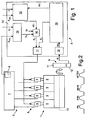
Figure 1 shows, schematically, injection control of an internal combustion engine in accordance with the invention; -
Figure 2 shows an injection strategy implemented by the internal combustion engine; -
Figure 3 shows a block diagram of a series of operations performed in the control method according to the teachings of the present invention. -
Number 1 inFigure 1 indicates a direct-injection diesel engine equipped with a commonrail injection system 2, and anelectronic control system 3 for controlling the fuel quantity to be injected intoengine 1 at each injection. - Of common
rail injection system 2 andelectronic control system 3,Figure 1 only shows the parts strictly necessary for a clear understanding of the present invention. - Common
rail injection system 2 comprises a number ofinjectors 4 supplying high-pressure fuel torespective cylinders 5 ofengine 1; a high-pressure feed circuit 6 comprising a common rail 7 supplying high-pressure fuel toinjectors 4; and a low-pressure feed circuit (not shown) supplying low-pressure fuel to high-pressure feed circuit 6. - Common
rail injection system 2 implements a fuel injection strategy in which consecutive multiple injections are made into eachcylinder 5 ofengine 1 at each engine cycle. - In the example shown in
Figure 2 , the multiple injections comprise a main injection MAIN made around the end-of-compression top dead centre position; a first pre-injection PIL before the main injection and made during the compression stroke; a second pre-injection PRE before the main injection MAIN and after the first pre-injection PIL; and a post-injection AFTER following the main injection MAIN; the second pre-injection PRE and the post-injection AFTER being made close enough to the main injection MAIN to assist the main injection in the actual fuel combustion stage. - More detailed information about multiple injections can be found in
European Patent Application 00104651.5 EP1035314 on 13.09.2000. - With reference to
Figure 1 ,electronic control system 3 comprises apressure sensor 8 located in common rail 7 and supplying an electric signal indicating the fuel pressure PRAILin common rail 7; and a detectingdevice 9 for instantaneously detecting the speed and angular position of the drive shaft 10 (shown schematically by a dot-and-dash line inFigure 1 ), and in turn comprising a knownpulse wheel 11 fitted to driveshaft 10, and anelectromagnetic sensor 12 associated withpulse wheel 11 and generating a movement signal M indicating the speed and angular position ofdrive shaft 10. -
Electronic control system 3 also comprises an electroniccentral control unit 13 connected topressure sensor 8 and detectingdevice 9, and supplying drive signals forinjectors 4. - Electronic
central control unit 13 comprises anominal energization block 14, which calculates a nominal energization time EN ofinjectors 4 for each injection and eachinjector 4 as a function of the fuel pressure PRAIL in common rail 7 ofinjection system 2, and of the nominal fuel quantity Qi to be injected intoengine 1. - More specifically,
nominal energization block 14 stores a nominal energization map defining the nominal energization time/quantity injected by aninjector 4 characteristic as a function of the fuel pressure PRAIL in common rail 7, i.e. containing, for each value of nominal fuel quantity Qi to be injected, and of fuel pressure PRAIL in common rail 7, a respective nominal energization time EN value ofinjector 4. - Unlike known control systems,
control system 3 according to the present invention makes a specific correction of small nominal fuel quantities to eliminate the difference between these and the fuel quantities actually injected into the engine. - In the example shown, and as described in detail later on,
control system 3 implements a correction strategy on the energization times of injectors performing injections of a fuel quantity within the "low-flow" region of the nominal energization time/injected quantity characteristic; which region is defined by all the energization time/injected quantity values in the initial portion (increasing from zero) and below a limit threshold SQ corresponding to a predetermined fuel quantity. - With reference to
Figure 1 , electroniccentral control unit 13 also comprises acorrection block 15 for correcting energization times EN relating to fuel quantities below threshold SQ, and which receives the fuel pressure PRAIL in common rail 7, and information C relative to the cylinder to be injected, and supplies a correction or offset energization time ET indicating the correction to be made to nominal energization time EN relative to a fuel quantity below threshold SQ, so that the fuel quantity actually injected substantially equals the nominal fuel quantity Qi required by the user. - More specifically,
correction block 15 comprises an electronic correction map defined, for example, by a three-dimensional matrix, and containing, for each value of fuel pressure PRAIL in common rail 7, and as a function of the cylinder to be injected, a respective correction energization time ET indicating the correction to be made to a respective nominal energization time EN generated bynominal energization block 14 and supplied to controlinjector 4 in a given engine cycle. - In the example shown, correction energization time ET may be calculated by processing the electronic correction map by means of a known linear interpolation operation (not described in detail) and as a function of the cylinder C to be injected, and of injection pressure PRAIL.
- Electronic
central control unit 13 implements an update strategy - described in detail later on - on correction energization times ET in the electronic correction map to ensure elimination of the difference between the nominal and actually injected fuel quantities, caused by deviations, e.g. induced by ageing of the injectors, in the nominal characteristics of the injectors. - In connection with the above, it should be pointed out that correction energization times ET may be initialized when calibrating common
rail injection system 2 under nominal injector operating conditions, or may be calculated directly using the update strategy described below. - With reference to
Figure 1 , electroniccentral control unit 13 also comprises aprocessing block 16, which receives nominal energization time EN, correction energization time ET, and the nominal fuel quantity Qi to be injected, and which supplies a corrected energization time Ec. -
Processing block 16 determines whether the fuel quantity to be injected is below threshold SQ or not, and, depending on the outcome, whether nominal energization time EN is to be corrected or not. In the example shown, if the nominal fuel quantity is above threshold SQ,processing block 16 determines corrected energization time Ec as a function of nominal energization time EN. Conversely, i.e. if the nominal fuel quantity is below threshold SQ,processing block 16 calculates corrected energization time Ec by correcting nominal energization time EN as a function of correction energization time ET. - More specifically, if the nominal fuel quantity is below threshold SQ,
processing block 16 may determine corrected energization time Ec by means of a predetermined operation, e.g. in the example shown, an algebraic subtraction operation between nominal energization time EN and correction energization time ET. - In the example shown, the above correction is conveniently applied to injections of small fuel quantities, which, in the multiple-injection strategy described above, are first pre-injection PIL, second pre-injection PRE, and post-injection AFTER.
- In connection with the above, it should be pointed out that
processing block 16 may make the above correction of nominal energization time EN by performing a further operation to vary correction energization time ET (between zero and its whole value) as a function of the type of injection to be made - so as to adjust the injected quantity according to whether the type of injection is first pre-injection PIL, second pre-injection PRE, or post-injection AFTER - and as a function of nominal energization time EN. - With reference to
Figure 1 , electroniccentral control unit 13 also comprises acontrol block 17, which receives corrected energization time Ec, and supplies the drive signals for controllinginjectors 4. - With reference to
Figure 1 , electroniccentral control unit 13 also comprises anacceleration computing block 18, which receives the movement signal M supplied by detectingdevice 9, and processes it to supply the instantaneous acceleration Acc ofdrive shaft 10, which is used to update correction energization times ET in the electronic correction map as described in detail later on; and anupdating block 19, which receives acceleration Acc to implement the above update strategy of the electronic correction map incorrection block 15. - More specifically, the electronic correction map update strategy is based on the principle of performing, for each correction energization time ET relative to an injection to be made in a given
cylinder 5 and at a given pressure PRAIL, a succession of energizations, with gradually increasing energization times, of theinjector 4 relative tocylinder 5; measuring a quantity related to the output torque ofdrive shaft 10 in response to the succession of energizations; and determining correction energization time ET as a function of the measured quantity. In the example shown, the quantity related to the output torque ofdrive shaft 10 is defined by acceleration Acc ofdrive shaft 10. - Updating
block 19 updates correction energization time ET as a function of measured acceleration Acc by performing a series of operations described below with reference to theFigure 3 flow chart. - As shown in
Figure 3 , in afirst block 100, updatingblock 19 determines whether the operating conditions ofengine 1 and commonrail injection system 2 permit updating of the correction map incorrection block 15. - More specifically, the operating conditions of
engine 1 permitting updating of the correction map are : release condition ofengine 1, i.e. zero fuel quantity injected and no engine torque increase demanded; engine temperature above a given minimum threshold; and drive shaft rotation speed within a predetermined rotation speed range. - If the operating conditions of
engine 1 permitting updating of the correction map are present (YES output of block 100),block 100 goes on to ablock 110. Conversely, if the engine operating conditions are not present (NO output of block 100),block 100 goes back to its input until such operating conditions occur. -
Block 110 determines the correction energization time ET to be updated in the correction map, and therefore the corresponding map coordinates defined by the cylinder and pressure. For the sake of simplicity, reference is made below to updating a correction energization time ET1 in the electronic correction map corresponding to a cylinder C1 and fuel injection pressure P1. - At this step, electronic
central control unit 13 checks the fuel pressure PRAIL in common rail 7 in known manner by means of a known pressure regulator (not shown), and sets it to pressure P1 relative to the correction energization time ET1 to be updated. -
Block 110 is followed by ablock 120, which determines the initial energization time ET ofinjector 4 relative to cylinder C1. More specifically, inblock 120, the energization time ET of the cylinder C1 injector is initialized at a value equal to a minimum energization time ETmin (ET = ETmin), which may be set to generate injection of, say, a zero fuel quantity on the cylinder C1 injector. -
Block 120 is followed by ablock 130, which determines: an incremental energization time dE indicating an increment to be added, at each engine cycle, to the energization time ET of the cylinder C1 injector to generate the increasing succession of injector energizations; and an acceleration threshold Sa, which is used as a reference value to update correction energization time ET. - More specifically, acceleration threshold Sa corresponds to acceleration of
drive shaft 10 following injection of a reference fuel quantity QR into cylinder C1, and is determined by adding an additional acceleration value Kag to a predetermined calibration acceleration value Ka. - More specifically, additional acceleration value Kag is calculated by calculating the arithmetic average of a series of accelerations measured prior to the step of performing the succession of injector energizations.
- Acceleration threshold Sa is conveniently determined according to the following equation:

drive shaft 10 measured prior to commencing the increasing succession of injector energizations. -
Block 130 is followed by ablock 140, in which the step of exciting the cylinder C1 injector 4 is commenced. More specifically, inblock 140, updatingblock 19 supplies the calculated energization time ET to controlblock 17, which generates the corresponding drive signal to be supplied to the cylinder C1 injector. -
Block 140 is followed by ablock 150, which acquires acceleration Acc ofdrive shaft 10, and compares this with acceleration threshold Sa. - If acceleration Acc is below acceleration threshold Sa (Acc < Sa) (NO output of block 150),
block 150 goes on to ablock 160. Conversely, if acceleration Acc substantially equals acceleration threshold Sa (Acc = Sa) (Yes output of block 150),block 150 goes on to ablock 170. - In
block 160, energization time ET is incremented by a value equal to incremental energization time dE. More specifically,block 160 calculates the energization time ET(i+1) of the cylinder C1 injector in the i+1-th engine cycle according to the equation:
-
Block 160 is followed byblock 140, in which the incremented energization time ET (relative to the i+1-th injection) is supplied tocontrol block 17, which generates the corresponding drive signal to be supplied to the cylinder C1 injector in the i+1-th engine cycle. - More specifically, the sequence of operations performed in
blocks drive shaft 10, which terminates when the acceleration threshold Sa ofdrive shaft 10 is found to be reached inblock 150. - As stated, when acceleration threshold Sa is reached (YES output of block 150),
block 150 is followed byblock 170, in which, by means of the nominal energization map (in nominal energization block 14), updatingblock 19 determines the nominal energization time EN relative to reference fuel quantity QR corresponding to the fuel quantity injected by the cylinder C1 injector at the last engine cycle, i.e. the engine cycle in which acceleration threshold Sa was reached. -
Block 170 is followed by ablock 180, in which updatingblock 19 calculates a new correction energization time ET in the correction map as a function of energization time ET and nominal energization time EN. - More specifically,
block 180 performs a subtraction operation between the nominal energization time EN calculated inblock 170, and the energization time ET corresponding to acceleration threshold Sa being reached. In other words, block 180 performs the following equation:
- The correction energization time ET resulting from the above operation is updated in the electronic correction map following an appropriate known filtration operation.
- In connection with the above, it should be pointed out that, once a correction energization time ET is updated, the above operations are repeated sequentially for all the non-updated correction energization times ET in the correction map.
-
Acceleration computing block 18 provides for processing the movement signal M to calculate acceleration signal Acc as a function of speed and angular position, and implements apulse wheel 11 correction strategy to filter from acceleration signal Acc any geometrical errors occurring in the manufacture and assembly ofpulse wheel 11. - More specifically, for a four-cylinder engine, acceleration Acc of
drive shaft 10 is calculated by processing the travel times of two angular windows, each with predetermined angular width and position with respect to the top dead centre TDC positions of the cylinders in order of combustion. - The acceleration correction strategy is implemented when
engine 1 is in the release condition, is at a temperature above a predetermined threshold, and is at such a speed that deceleration is substantially constant. - In the example shown, the acceleration correction strategy is based on determining an angular correction coefficient Kc of one of the two intervals, e.g. the second angular interval of a size hereinafter indicated ß, and assuming the other angular interval, of a size hereinafter indicated , is correct. This strategy therefore assumes no errors in the speed and acceleration Acc calculation with respect to the first angular interval
- More specifically, angular correction coefficient Kc of second angular interval ß is calculated by performing the following operations:
- movement signal M is processed to determine the
pulse wheel 11 travel times t(2i) and t(2i+2) (relative to cycles 2i and 2i+2 respectively) of the first angular window relative to first angular interval :- movement signal M is processed to determine the travel time t(2i+1) (relative to cycle 2i+1) of the second angular window relative to second angular interval ß;
- assuming the angular window relative to first angular interval is correct, and that deceleration is constant, engine speed is calculated according to the equation:

acceleration computing block 18 to determine the error in second angular interval ß :
- In connection with the above, it should be pointed out that, to minimize and further filter the effect on the Acc acceleration calculation of disturbance or noise sources produced, for example, by rough road conditions or other causes,
acceleration computing block 18 provides for calculating a corrected output acceleration Acc value by processing both acceleration Acc of the cylinder considered, and the accelerations of adjacent cylinders in order of combustion. - More specifically,
acceleration computing block 18 corrects acceleration Acc of the cylinder considered, and the accelerations of adjacent cylinders in order of combustion, and then calculates the acceleration Acc to be supplied at the output by implementing an arithmetical average of the corrected accelerations. - The advantages of the present invention will be clear from the foregoing description.
- In particular, the main advantage of the present invention lies in compensating for all the factors (injector characteristic spread and drift, injection system ageing, etc.) responsible for deviations in small injected fuel quantities, with obvious benefits in terms of reducing noise caused by dispersion of the fuel quantity injected by first pre-injection PIL and second pre-injection PRE, and controlling exhaust gas emission levels over the working life of the vehicle.
- The device is also particularly advantageous in that the step of updating the electronic correction map in
correction block 15, besides ensuring minimum oscillations of the "driveline" and therefore of the vehicle system as a whole, also ensures barely perceptible combustion noise by gradually increasing very small injected quantities. - Clearly, changes may be made to the device as described and illustrated herein without, however, departing from the scope of the present invention.
Claims (20)
- A control method for controlling the fuel quantity injected into an internal combustion engine (1) comprising a number of injectors (4), each for injecting a given fuel quantity into a respective cylinder (5); for each injection inside a cylinder (5) of said engine (1), said method comprising the step of:- determining (14) a nominal energization time (EN) of the injector involved in said injection, as a function of injection pressure (PRAIL) and the required nominal fuel quantity (Qi);said method being characterized by also comprising the steps of:- determining (15) a correction energization time (ET) as a function of injection pressure (PRAIL) and the cylinder (5) involved in the injection;- determining (16), in the event the required nominal fuel quantity (Qi) is below a predetermined threshold (SQ), a corrected energization time (EC) by correcting said nominal energization time (EN) as a function of said correction energization time ( ET); and- exciting said injector for a time equal to said corrected energization time (EC);said step of determining said correction energization time ( ET) comprising the steps of:- performing, in the presence of a predetermined series of operating conditions of said engine (1), a succession of energizations of said injector (4) of gradually increasing energization times (ET);- determining a quantity (Acc) related to the output torque of said engine (1) in response to said succession of energizations; and- calculating said correction energization time (ET) as a function of said quantity (Acc) related to the output torque.
- A control method as claimed in Claim 1, characterized in that said step of calculating the correction energization time (ET) comprises the step of determining an actual energization time (ET) of said injector, when said quantity (Acc) related to the output torque of said engine in response to said succession of energizations satisfies a predetermined relationship with a threshold (Sa) corresponding to a reference fuel quantity (QR) .
- A control method as claimed in Claim 2, characterized in that said predetermined relationship is defined by the condition that said quantity (Acc) related to the output torque of said engine in response to said succession of energizations be equal to said threshold (Sa).
- A control method as claimed in Claims 2 and 3, characterized in that said step of calculating said correction energization time ( ET) comprises the step of calculating said correction energization time ( ET) as a function of said actual energization time (ET) and of the nominal energization time (EN) corresponding to the reference fuel quantity (QR) .
- A control method as claimed in any one of the foregoing Claims, characterized by comprising the step of generating a correction map (15) storing a number of correction energization times ( ET), each relative to a respective operating state of the injection system defined by injection pressure (PRAIL) and by the cylinder (C) to be injected.
- A control method as claimed in Claim 5, characterized in that said step of determining said correction energization time ( ET) comprises the step of updating each said correction energization time ( ET) in said correction map as a function of said actual energization time (ET) .
- A control method as claimed in any one of Claims 2 to 6, characterized in that said step of performing a succession of energizations of said injector (4) of gradually increasing energization times (ET) comprises the steps of:- determining (120) an initial energization time (ETmin) of the injector (4) involved in said succession of energizations;- determining (130) an incremental energization time (dE) indicating an increment to be added, at each engine cycle, to the initial energization time (ETmin) to generate said succession of energizations; and- determining said threshold (Sa) as a function of the reference fuel quantity (QR) .
- A control method as claimed in any one of the foregoing Claims, characterized in that said step of determining a quantity (Acc) related to the output torque of said engine (1) in response to said succession of energizations comprises the step of determining (150) the acceleration (Acc) of said engine (1).
- A control method as claimed in Claim 8, characterized in that said step of determining an actual energization time (ET) of said injector (4) comprises the step of determining the actual energization time (ET) when said acceleration (Acc) of said engine (1) satisfies a predetermined relationship with said threshold (Sa).
- A control method as claimed in Claims 8 and 9, characterized in that said step of determining the acceleration (Acc) of said engine (1) comprises the step of processing the travel times of at least two angular windows (α, β) of a pulse wheel (11) fitted to the shaft (10) of said engine (1), each angular window having predetermined angular width and position.
- A control method as claimed in Claim 10, characterized in that said step of determining the acceleration (Acc) of said engine (1) comprises the step of determining a correction coefficient Kc of the angular interval of one of the two angular windows (α, β) according to the following equation:

- A control device (3) for controlling the fuel quantity injected into an internal combustion engine comprising a number of injectors (4), each for injecting a given fuel quantity into a respective cylinder (5); said control device (3) being characterized by comprising:- energization means (14) for determining a nominal energization time (EN) of said injector (4) as a function of injection pressure (PRAIL) and the nominal fuel quantity (Qi) required by the user;- correcting means (15, 19) for determining a correction energization time (ET) as a function of injection pressure (PRAIL) and the cylinder (5) involved in said injection;- control means (16) for determining, in the event the required nominal fuel quantity (Qi) is below a predetermined threshold (SQ), a corrected energization time (EC) by correcting said nominal energization time (EN) as a function of said correction energization time ( ET) ; and- drive means (16) for exciting said injector (4) for a time equal to said corrected energization time (EC) ;said correcting means (15, 19) comprising:- control means (140) for performing, in the presence of a predetermined series of operating conditions (100) of said engine (1), a succession of energizations of an injector (4) with gradually increasing energization times (ET);- detecting means (150) for determining a quantity (Acc) related to the output torque of said engine (1) in response to said succession of energizations; and- processing means (170, 180) for calculating said correction energization time (ET) as a function of said quantity (Acc) related to the output torque.
- A control device as claimed in Claim 12, characterized in that said processing means (170, 180) comprise first calculating means (170) for determining an actual energization time (ET) of said injector (4) when said quantity (Acc) related to the output torque satisfies a predetermined relationship with a threshold (Sa) corresponding to a reference fuel quantity (QR).
- A control device as claimed in Claim 13, characterized in that said predetermined relationship is defined by the condition that said quantity (Acc) related to the output torque of said engine in response to said succession of energizations be equal to said threshold (Sa) .
- A control device as claimed in Claim 14 or 13, characterized in that said processing means (170, 180) comprise second calculating means (180) for determining said correction energization time ( ET) as a function of said actual energization time (ET) and of the nominal energization time (EN) corresponding to the reference fuel quantity (QR).
- A control device as claimed in any one of Claims 12 to 15, characterized in that said correcting means (15) comprise a correction map (15) storing a number of correction energization times ( ET), each relative to a respective operating state of the injection system (2) defined by injection pressure (PRAIL) and by the cylinder (C) to be injected.
- A control device as claimed in any one of Claims 12 to 16, characterized in that said correcting means (19) comprise:- third calculating means (110) for determining an initial energization time (ETmin) of the injector (4) involved in said succession of energizations; and- fourth calculating means (130) for determining said threshold (Sa), and an incremental energization time (dE) indicating an increment to add, at each engine cycle, to said initial energization time (ETmin) to generate said succession of energizations.
- A control device as claimed in any one of Claims 12 to 17, characterized by comprising measuring means (18) for supplying said correcting means (19) with said quantity related to the torque of the engine (1).
- A control device as claimed in Claim 18; characterized in that said quantity related to the torque of the engine (1) is defined by the acceleration of said engine (1).
- A control device as claimed in Claim 19, characterized by comprising a pulse wheel (11) fitted to the shaft (10) of said engine (1); and an electromagnetic sensor (12) associated with the pulse wheel (11) and generating a movement signal (M) related to the speed and angular position of the shaft (10); said measuring means (18) processing said movement signal (M) and said speed to supply the acceleration (Acc) of said shaft (10) of said engine (1).
Applications Claiming Priority (2)
| Application Number | Priority Date | Filing Date | Title |
|---|---|---|---|
| IT000698A ITTO20020698A1 (en) | 2002-08-06 | 2002-08-06 | QUALITY CONTROL METHOD AND DEVICE |
| ITTO20020698 | 2002-08-06 |
Publications (3)
| Publication Number | Publication Date |
|---|---|
| EP1388661A2 EP1388661A2 (en) | 2004-02-11 |
| EP1388661A3 EP1388661A3 (en) | 2004-10-13 |
| EP1388661B1 true EP1388661B1 (en) | 2009-12-30 |
Family
ID=11459560
Family Applications (1)
| Application Number | Title | Priority Date | Filing Date |
|---|---|---|---|
| EP03017854A Expired - Lifetime EP1388661B1 (en) | 2002-08-06 | 2003-08-05 | Method and device for controlling the fuel quantity injected into an internal combustion engine, in particular a diesel engine equipped with a common rail injection system |
Country Status (6)
| Country | Link |
|---|---|
| US (1) | US6779511B2 (en) |
| EP (1) | EP1388661B1 (en) |
| JP (1) | JP4387722B2 (en) |
| AT (1) | ATE453795T1 (en) |
| DE (1) | DE60330734D1 (en) |
| IT (1) | ITTO20020698A1 (en) |
Families Citing this family (26)
| Publication number | Priority date | Publication date | Assignee | Title |
|---|---|---|---|---|
| EP1865177A3 (en) * | 2001-10-15 | 2008-12-24 | STMicroelectronics S.r.l. | Injection control method for an internal combustion engine, in particular a Diesel engine, and corresponding control system |
| CA2441686C (en) * | 2003-09-23 | 2004-12-21 | Westport Research Inc. | Method for controlling combustion in an internal combustion engine and predicting performance and emissions |
| EP1526267A3 (en) * | 2003-10-21 | 2010-07-28 | Continental Automotive GmbH | Method and device for compensating the drift of an injector for an internal combustion engine with direct injection |
| JP2005127164A (en) * | 2003-10-21 | 2005-05-19 | Denso Corp | Common rail fuel injection system |
| US20060162689A1 (en) * | 2005-01-25 | 2006-07-27 | Visteon Global Technologies, Inc. | Method of controlling diesel engine combustion process in a closed loop using ionization feedback |
| EP1705355B1 (en) * | 2005-03-25 | 2008-02-20 | Delphi Technologies, Inc. | Method for determining operating parameters of an injection system |
| EP1813796A3 (en) * | 2006-01-26 | 2007-12-19 | Delphi Technologies, Inc. | Controller and control method for an engine control unit |
| DE102006015967A1 (en) * | 2006-04-05 | 2007-10-18 | Siemens Ag | Adaptation method of an injection system of an internal combustion engine |
| SE529742C2 (en) * | 2006-04-07 | 2007-11-13 | Scania Cv Abp | Method for adjusting a look-up table and a system for controlling an injector of a cylinder in an internal combustion engine |
| US7480557B2 (en) * | 2006-11-17 | 2009-01-20 | Honda Motor Co., Ltd. | Control system for internal combustion engine |
| FR2910551B1 (en) * | 2006-12-21 | 2009-02-20 | Renault Sas | METHOD FOR CORRECTING INJECTOR DERIVATIVES OF AN ENGINE |
| FR2910549A1 (en) * | 2006-12-21 | 2008-06-27 | Renault Sas | Injector drift correcting method for e.g. diesel engine of vehicle, involves determining drift correction value of injector to be added to nominal set point value by utilizing indicated average torque estimation for cylinders |
| DE102007024823B4 (en) * | 2007-05-29 | 2014-10-23 | Continental Automotive Gmbh | Method and device for determining a drive parameter for a fuel injector of an internal combustion engine |
| FR2917462B1 (en) * | 2007-06-12 | 2009-09-04 | Renault Sas | METHOD FOR CORRECTING INJECTOR DERIVATIVES OF AN ENGINE |
| DE102007034335A1 (en) * | 2007-07-24 | 2009-01-29 | Robert Bosch Gmbh | Method for determining the injected fuel mass of a pilot injection |
| JP4858345B2 (en) * | 2007-07-25 | 2012-01-18 | 株式会社デンソー | Fuel injection control device and fuel injection system using the same |
| DE102008004365A1 (en) * | 2008-01-15 | 2009-07-16 | Robert Bosch Gmbh | Method for operating an internal combustion engine, computer program and control unit |
| EP2098709B1 (en) * | 2008-03-04 | 2016-07-06 | GM Global Technology Operations LLC | A method for operating an internal combustion engine |
| DE102008002482B4 (en) | 2008-06-17 | 2024-11-28 | Robert Bosch Gmbh | Method and device for calibrating a fuel metering system of an internal combustion engine, in particular of a motor vehicle |
| GB2475060A (en) * | 2009-11-03 | 2011-05-11 | Gm Global Tech Operations Inc | Estimating fuel injecting pressure in an i.c. engine |
| DE102010014320B4 (en) | 2010-04-09 | 2016-10-27 | Continental Automotive Gmbh | Method for adjusting the actual injection quantity, injection device and internal combustion engine |
| CA2754137C (en) | 2011-09-30 | 2012-11-20 | Westport Power Inc. | Apparatus and method for in situ fuel injector calibration in an internal combustion engine |
| FR2982644B1 (en) | 2011-11-10 | 2014-01-10 | Peugeot Citroen Automobiles Sa | METHOD FOR CONTROLLING A FUEL SUPPLY OF AN INTERNAL COMBUSTION ENGINE EQUIPPED WITH A MOTOR VEHICLE |
| EP2685074B1 (en) | 2012-07-13 | 2018-04-18 | Delphi Automotive Systems Luxembourg SA | Fuel injection control in an internal combustion engine |
| DE102012222899A1 (en) * | 2012-12-12 | 2014-06-12 | Robert Bosch Gmbh | Method for determining the fuel quality in an internal combustion engine, in particular of a motor vehicle |
| CN104747338B (en) * | 2013-12-26 | 2017-06-13 | 联创汽车电子有限公司 | The oil quantity correction method of high pressure common rail injector zero and zero oil mass Self-correc ting control module |
Family Cites Families (11)
| Publication number | Priority date | Publication date | Assignee | Title |
|---|---|---|---|---|
| US4357662A (en) * | 1978-05-08 | 1982-11-02 | The Bendix Corporation | Closed loop timing and fuel distribution controls |
| JPH07111151B2 (en) * | 1984-01-10 | 1995-11-29 | 日本電装株式会社 | Fuel injection amount control device for diesel engine |
| DE4312587C2 (en) * | 1993-04-17 | 2002-08-01 | Bosch Gmbh Robert | Method and device for controlling a fuel injection system |
| FR2720787B1 (en) * | 1994-06-06 | 1996-07-26 | Renault Vehicules Ind | Method and device for determining the specific parameters of the injectors of a combustion engine, in particular of a pre-injection diesel engine. |
| DE19700711C2 (en) * | 1997-01-10 | 1999-05-12 | Siemens Ag | Method for compensating for the systematic error in injection devices for an internal combustion engine |
| US6408242B1 (en) * | 1997-12-11 | 2002-06-18 | Cummins, Inc. | Apparatus and method for diagnosing and controlling an ignition system of an internal combustion engine |
| US6006156A (en) * | 1997-12-11 | 1999-12-21 | Cummins Engine Company, Inc. | Apparatus and method for diagnosing and controlling an ignition system of an internal combustion engine |
| DE60022918T2 (en) * | 1999-01-13 | 2006-07-20 | Delphi Technologies, Inc., Troy | Control method for a self-igniting internal combustion engine |
| JP3695213B2 (en) * | 1999-04-02 | 2005-09-14 | いすゞ自動車株式会社 | Common rail fuel injection system |
| US6516782B1 (en) * | 1999-05-27 | 2003-02-11 | Detroit Diesel Corporation | System and method for controlling fuel injections |
| JP4206563B2 (en) * | 1999-06-18 | 2009-01-14 | 株式会社デンソー | Fuel injection device |
-
2002
- 2002-08-06 IT IT000698A patent/ITTO20020698A1/en unknown
-
2003
- 2003-08-05 US US10/633,688 patent/US6779511B2/en not_active Expired - Lifetime
- 2003-08-05 AT AT03017854T patent/ATE453795T1/en not_active IP Right Cessation
- 2003-08-05 EP EP03017854A patent/EP1388661B1/en not_active Expired - Lifetime
- 2003-08-05 DE DE60330734T patent/DE60330734D1/en not_active Expired - Lifetime
- 2003-08-05 JP JP2003287116A patent/JP4387722B2/en not_active Expired - Lifetime
Also Published As
| Publication number | Publication date |
|---|---|
| ITTO20020698A1 (en) | 2004-02-07 |
| JP2004132360A (en) | 2004-04-30 |
| JP4387722B2 (en) | 2009-12-24 |
| US20040089273A1 (en) | 2004-05-13 |
| US6779511B2 (en) | 2004-08-24 |
| EP1388661A2 (en) | 2004-02-11 |
| ITTO20020698A0 (en) | 2002-08-06 |
| EP1388661A3 (en) | 2004-10-13 |
| ATE453795T1 (en) | 2010-01-15 |
| DE60330734D1 (en) | 2010-02-11 |
Similar Documents
| Publication | Publication Date | Title |
|---|---|---|
| US6779511B2 (en) | Method and device for controlling the fuel quantity injected into an internal combustion engine, in particular a diesel engine equipped with a common rail injection system | |
| EP2031221B1 (en) | Fuel injection system with injection characteristic learning function | |
| US7474952B2 (en) | Fuel injection controller | |
| EP1930577A1 (en) | Fuel injection control device for diesel engine | |
| US20110106409A1 (en) | Method and device for the pressure wave compensation during consecutive injections in an injection system of an internal combustion engine | |
| EP1338781B1 (en) | Accumulation type fuel injection system | |
| US7725242B2 (en) | Controller of internal combustion engine | |
| US7588515B2 (en) | Fuel injection controller of internal combustion engine | |
| US20120221227A1 (en) | Method for operating an internal combustion engine | |
| US5251437A (en) | Method and system for controlling air/fuel ratio for internal combustion engine | |
| US6877485B2 (en) | Method and device for controlling an internal combustion engine | |
| JP2017516018A (en) | Method and apparatus for calibrating post-injection of an internal combustion engine | |
| EP1020629B1 (en) | Control method for a compression ignition engine | |
| US6298830B1 (en) | Method of jetting high-pressure fuel and apparatus therefor | |
| JP2001289099A (en) | Fuel pressure control device for internal combustion engine | |
| JP2010533817A (en) | Method and apparatus for determining fuel injection quantity for pre-injection | |
| US7025043B2 (en) | Method for balancing the torque generated by the cylinders of an internal combustion engine, in particular a direct-injection diesel engine provided with a common rail injection system | |
| GB2351816A (en) | Controlling multi-phase fuel injection in an internal combustion engine | |
| US6932059B2 (en) | Fuel injection system of internal combustion engine | |
| JP5311909B2 (en) | Method for determining injected fuel mass | |
| EP2336535B1 (en) | Correction amount control method for fuel injection amount correction and common rail fuel injection control apparatus | |
| JP4529892B2 (en) | Fuel injection control device for multi-cylinder engine | |
| JP4706670B2 (en) | Fuel injection control device for diesel engine | |
| US7765979B2 (en) | System for controlling the operation of a diesel engine of a motor vehicle | |
| KR100992665B1 (en) | Fuel level correction method according to injector aging |
Legal Events
| Date | Code | Title | Description |
|---|---|---|---|
| PUAI | Public reference made under article 153(3) epc to a published international application that has entered the european phase |
Free format text: ORIGINAL CODE: 0009012 |
|
| AK | Designated contracting states |
Kind code of ref document: A2 Designated state(s): AT BE BG CH CY CZ DE DK EE ES FI FR GB GR HU IE IT LI LU MC NL PT RO SE SI SK TR |
|
| AX | Request for extension of the european patent |
Extension state: AL LT LV MK |
|
| PUAL | Search report despatched |
Free format text: ORIGINAL CODE: 0009013 |
|
| AK | Designated contracting states |
Kind code of ref document: A3 Designated state(s): AT BE BG CH CY CZ DE DK EE ES FI FR GB GR HU IE IT LI LU MC NL PT RO SE SI SK TR |
|
| AX | Request for extension of the european patent |
Extension state: AL LT LV MK |
|
| 17P | Request for examination filed |
Effective date: 20050216 |
|
| AKX | Designation fees paid |
Designated state(s): AT BE BG CH CY CZ DE DK EE ES FI FR GB GR HU IE IT LI LU MC NL PT RO SE SI SK TR |
|
| GRAP | Despatch of communication of intention to grant a patent |
Free format text: ORIGINAL CODE: EPIDOSNIGR1 |
|
| GRAS | Grant fee paid |
Free format text: ORIGINAL CODE: EPIDOSNIGR3 |
|
| GRAA | (expected) grant |
Free format text: ORIGINAL CODE: 0009210 |
|
| AK | Designated contracting states |
Kind code of ref document: B1 Designated state(s): AT BE BG CH CY CZ DE DK EE ES FI FR GB GR HU IE IT LI LU MC NL PT RO SE SI SK TR |
|
| REG | Reference to a national code |
Ref country code: GB Ref legal event code: FG4D |
|
| REG | Reference to a national code |
Ref country code: CH Ref legal event code: EP |
|
| REG | Reference to a national code |
Ref country code: IE Ref legal event code: FG4D |
|
| REF | Corresponds to: |
Ref document number: 60330734 Country of ref document: DE Date of ref document: 20100211 Kind code of ref document: P |
|
| PG25 | Lapsed in a contracting state [announced via postgrant information from national office to epo] |
Ref country code: SE Free format text: LAPSE BECAUSE OF FAILURE TO SUBMIT A TRANSLATION OF THE DESCRIPTION OR TO PAY THE FEE WITHIN THE PRESCRIBED TIME-LIMIT Effective date: 20091230 Ref country code: FI Free format text: LAPSE BECAUSE OF FAILURE TO SUBMIT A TRANSLATION OF THE DESCRIPTION OR TO PAY THE FEE WITHIN THE PRESCRIBED TIME-LIMIT Effective date: 20091230 |
|
| REG | Reference to a national code |
Ref country code: NL Ref legal event code: VDEP Effective date: 20091230 |
|
| PG25 | Lapsed in a contracting state [announced via postgrant information from national office to epo] |
Ref country code: SI Free format text: LAPSE BECAUSE OF FAILURE TO SUBMIT A TRANSLATION OF THE DESCRIPTION OR TO PAY THE FEE WITHIN THE PRESCRIBED TIME-LIMIT Effective date: 20091230 |
|
| PG25 | Lapsed in a contracting state [announced via postgrant information from national office to epo] |
Ref country code: AT Free format text: LAPSE BECAUSE OF FAILURE TO SUBMIT A TRANSLATION OF THE DESCRIPTION OR TO PAY THE FEE WITHIN THE PRESCRIBED TIME-LIMIT Effective date: 20091230 |
|
| PG25 | Lapsed in a contracting state [announced via postgrant information from national office to epo] |
Ref country code: NL Free format text: LAPSE BECAUSE OF FAILURE TO SUBMIT A TRANSLATION OF THE DESCRIPTION OR TO PAY THE FEE WITHIN THE PRESCRIBED TIME-LIMIT Effective date: 20091230 Ref country code: BG Free format text: LAPSE BECAUSE OF FAILURE TO SUBMIT A TRANSLATION OF THE DESCRIPTION OR TO PAY THE FEE WITHIN THE PRESCRIBED TIME-LIMIT Effective date: 20100330 Ref country code: ES Free format text: LAPSE BECAUSE OF FAILURE TO SUBMIT A TRANSLATION OF THE DESCRIPTION OR TO PAY THE FEE WITHIN THE PRESCRIBED TIME-LIMIT Effective date: 20100410 Ref country code: EE Free format text: LAPSE BECAUSE OF FAILURE TO SUBMIT A TRANSLATION OF THE DESCRIPTION OR TO PAY THE FEE WITHIN THE PRESCRIBED TIME-LIMIT Effective date: 20091230 Ref country code: RO Free format text: LAPSE BECAUSE OF FAILURE TO SUBMIT A TRANSLATION OF THE DESCRIPTION OR TO PAY THE FEE WITHIN THE PRESCRIBED TIME-LIMIT Effective date: 20091230 Ref country code: PT Free format text: LAPSE BECAUSE OF FAILURE TO SUBMIT A TRANSLATION OF THE DESCRIPTION OR TO PAY THE FEE WITHIN THE PRESCRIBED TIME-LIMIT Effective date: 20100430 |
|
| PG25 | Lapsed in a contracting state [announced via postgrant information from national office to epo] |
Ref country code: BE Free format text: LAPSE BECAUSE OF FAILURE TO SUBMIT A TRANSLATION OF THE DESCRIPTION OR TO PAY THE FEE WITHIN THE PRESCRIBED TIME-LIMIT Effective date: 20091230 Ref country code: SK Free format text: LAPSE BECAUSE OF FAILURE TO SUBMIT A TRANSLATION OF THE DESCRIPTION OR TO PAY THE FEE WITHIN THE PRESCRIBED TIME-LIMIT Effective date: 20091230 Ref country code: CZ Free format text: LAPSE BECAUSE OF FAILURE TO SUBMIT A TRANSLATION OF THE DESCRIPTION OR TO PAY THE FEE WITHIN THE PRESCRIBED TIME-LIMIT Effective date: 20091230 |
|
| PG25 | Lapsed in a contracting state [announced via postgrant information from national office to epo] |
Ref country code: CY Free format text: LAPSE BECAUSE OF FAILURE TO SUBMIT A TRANSLATION OF THE DESCRIPTION OR TO PAY THE FEE WITHIN THE PRESCRIBED TIME-LIMIT Effective date: 20091230 Ref country code: GR Free format text: LAPSE BECAUSE OF FAILURE TO SUBMIT A TRANSLATION OF THE DESCRIPTION OR TO PAY THE FEE WITHIN THE PRESCRIBED TIME-LIMIT Effective date: 20100331 |
|
| PLBE | No opposition filed within time limit |
Free format text: ORIGINAL CODE: 0009261 |
|
| STAA | Information on the status of an ep patent application or granted ep patent |
Free format text: STATUS: NO OPPOSITION FILED WITHIN TIME LIMIT |
|
| 26N | No opposition filed |
Effective date: 20101001 |
|
| PG25 | Lapsed in a contracting state [announced via postgrant information from national office to epo] |
Ref country code: DK Free format text: LAPSE BECAUSE OF FAILURE TO SUBMIT A TRANSLATION OF THE DESCRIPTION OR TO PAY THE FEE WITHIN THE PRESCRIBED TIME-LIMIT Effective date: 20091230 |
|
| PG25 | Lapsed in a contracting state [announced via postgrant information from national office to epo] |
Ref country code: MC Free format text: LAPSE BECAUSE OF NON-PAYMENT OF DUE FEES Effective date: 20100831 |
|
| REG | Reference to a national code |
Ref country code: CH Ref legal event code: PL |
|
| GBPC | Gb: european patent ceased through non-payment of renewal fee |
Effective date: 20100805 |
|
| PG25 | Lapsed in a contracting state [announced via postgrant information from national office to epo] |
Ref country code: CH Free format text: LAPSE BECAUSE OF NON-PAYMENT OF DUE FEES Effective date: 20100831 Ref country code: LI Free format text: LAPSE BECAUSE OF NON-PAYMENT OF DUE FEES Effective date: 20100831 |
|
| PG25 | Lapsed in a contracting state [announced via postgrant information from national office to epo] |
Ref country code: IE Free format text: LAPSE BECAUSE OF NON-PAYMENT OF DUE FEES Effective date: 20100805 |
|
| PG25 | Lapsed in a contracting state [announced via postgrant information from national office to epo] |
Ref country code: GB Free format text: LAPSE BECAUSE OF NON-PAYMENT OF DUE FEES Effective date: 20100805 |
|
| PG25 | Lapsed in a contracting state [announced via postgrant information from national office to epo] |
Ref country code: LU Free format text: LAPSE BECAUSE OF NON-PAYMENT OF DUE FEES Effective date: 20100805 Ref country code: HU Free format text: LAPSE BECAUSE OF FAILURE TO SUBMIT A TRANSLATION OF THE DESCRIPTION OR TO PAY THE FEE WITHIN THE PRESCRIBED TIME-LIMIT Effective date: 20100701 |
|
| PG25 | Lapsed in a contracting state [announced via postgrant information from national office to epo] |
Ref country code: TR Free format text: LAPSE BECAUSE OF FAILURE TO SUBMIT A TRANSLATION OF THE DESCRIPTION OR TO PAY THE FEE WITHIN THE PRESCRIBED TIME-LIMIT Effective date: 20091230 |
|
| REG | Reference to a national code |
Ref country code: DE Ref legal event code: R082 Ref document number: 60330734 Country of ref document: DE Representative=s name: KOTITSCHKE & HEURUNG PARTNERSCHAFT MBB PATENT-, DE Ref country code: DE Ref legal event code: R082 Ref document number: 60330734 Country of ref document: DE Representative=s name: KOTITSCHKE & HEURUNG PARTNERSCHAFT MBB, DE Ref country code: DE Ref legal event code: R082 Ref document number: 60330734 Country of ref document: DE Representative=s name: DR. RALF KOTITSCHKE, DE |
|
| REG | Reference to a national code |
Ref country code: FR Ref legal event code: PLFP Year of fee payment: 14 |
|
| REG | Reference to a national code |
Ref country code: FR Ref legal event code: PLFP Year of fee payment: 15 |
|
| REG | Reference to a national code |
Ref country code: FR Ref legal event code: PLFP Year of fee payment: 16 |
|
| PGFP | Annual fee paid to national office [announced via postgrant information from national office to epo] |
Ref country code: IT Payment date: 20200807 Year of fee payment: 18 |
|
| PG25 | Lapsed in a contracting state [announced via postgrant information from national office to epo] |
Ref country code: IT Free format text: LAPSE BECAUSE OF NON-PAYMENT OF DUE FEES Effective date: 20210805 |
|
| PGFP | Annual fee paid to national office [announced via postgrant information from national office to epo] |
Ref country code: DE Payment date: 20220720 Year of fee payment: 20 |
|
| PGFP | Annual fee paid to national office [announced via postgrant information from national office to epo] |
Ref country code: FR Payment date: 20220721 Year of fee payment: 20 |
|
| REG | Reference to a national code |
Ref country code: DE Ref legal event code: R071 Ref document number: 60330734 Country of ref document: DE |