EP1388481A2 - Steering column for a vehicle - Google Patents
Steering column for a vehicle Download PDFInfo
- Publication number
- EP1388481A2 EP1388481A2 EP03017974A EP03017974A EP1388481A2 EP 1388481 A2 EP1388481 A2 EP 1388481A2 EP 03017974 A EP03017974 A EP 03017974A EP 03017974 A EP03017974 A EP 03017974A EP 1388481 A2 EP1388481 A2 EP 1388481A2
- Authority
- EP
- European Patent Office
- Prior art keywords
- steering
- column jacket
- column
- side walls
- steering column
- Prior art date
- Legal status (The legal status is an assumption and is not a legal conclusion. Google has not performed a legal analysis and makes no representation as to the accuracy of the status listed.)
- Withdrawn
Links
- 239000002184 metal Substances 0.000 claims abstract description 9
- 238000005452 bending Methods 0.000 claims abstract description 7
- 230000003014 reinforcing effect Effects 0.000 claims description 9
- 238000004519 manufacturing process Methods 0.000 description 6
- 229910000831 Steel Inorganic materials 0.000 description 4
- 238000000034 method Methods 0.000 description 4
- 239000010959 steel Substances 0.000 description 4
- 238000003466 welding Methods 0.000 description 2
- 238000005520 cutting process Methods 0.000 description 1
- 230000004048 modification Effects 0.000 description 1
- 238000012986 modification Methods 0.000 description 1
- 238000004513 sizing Methods 0.000 description 1
Images


Classifications
-
- B—PERFORMING OPERATIONS; TRANSPORTING
- B60—VEHICLES IN GENERAL
- B60R—VEHICLES, VEHICLE FITTINGS, OR VEHICLE PARTS, NOT OTHERWISE PROVIDED FOR
- B60R25/00—Fittings or systems for preventing or indicating unauthorised use or theft of vehicles
- B60R25/01—Fittings or systems for preventing or indicating unauthorised use or theft of vehicles operating on vehicle systems or fittings, e.g. on doors, seats or windscreens
- B60R25/02—Fittings or systems for preventing or indicating unauthorised use or theft of vehicles operating on vehicle systems or fittings, e.g. on doors, seats or windscreens operating on the steering mechanism
- B60R25/021—Fittings or systems for preventing or indicating unauthorised use or theft of vehicles operating on vehicle systems or fittings, e.g. on doors, seats or windscreens operating on the steering mechanism restraining movement of the steering column or steering wheel hub, e.g. restraining means controlled by ignition switch
- B60R25/02105—Arrangement of the steering column thereof
-
- B—PERFORMING OPERATIONS; TRANSPORTING
- B62—LAND VEHICLES FOR TRAVELLING OTHERWISE THAN ON RAILS
- B62D—MOTOR VEHICLES; TRAILERS
- B62D1/00—Steering controls, i.e. means for initiating a change of direction of the vehicle
- B62D1/02—Steering controls, i.e. means for initiating a change of direction of the vehicle vehicle-mounted
- B62D1/16—Steering columns
- B62D1/18—Steering columns yieldable or adjustable, e.g. tiltable
- B62D1/184—Mechanisms for locking columns at selected positions
Definitions
- the present invention relates to a steering column for a vehicle.
- a vehicle steering column has a steering shaft and a column jacket accommodating therein the steering shaft.
- the column jacket is conventionally prepared by subjecting a steel pipe to e.g. a pipe expanding/contracting process.
- the steel pipe is usually more expensive than a metal plate.
- the processing of the steel pipe into the column jacket is also costly. As a result, the manufacturing cost of the column jacket becomes relatively high.
- a steering column comprising: a steering shaft; a column jacket accommodating therein the steering shaft, the column jacket being integrally formed by bending a metal plate into a substantially U-shape to define a pair of opposed side walls and arranged with an opening of the U-shape facing downward; upper and lower brackets mounted on upper and lower ends of the column jacket, respectively; and upper and lower bearings fixed to the upper and lower brackets, respectively, to support the steering shaft rotatably.
- a steering column comprising: a steering shaft; a column jacket accommodating therein the steering shaft, the column jacket being formed into one piece and having a substantially U-shape in cross section throughout its length to define a pair of opposed side walls extending axially of the steering column; upper and lower brackets mounted on upper and lower ends of the column jacket, respectively; upper and lower bearings fixed to the upper and lower brackets, respectively, to support the steering shaft rotatably
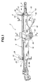
- FIG. 1 is a partially sectional view of a steering column according to an embodiment of the present invention.
- FIG. 2 is a plan view of the steering column, when viewed in the direction of an arrow II of FIG. 1.
- FIG. 3 is a plan view of the steering column, when viewed in the direction of an arrow III of FIG. 1.
- FIG. 4 is an enlarged view of part of the steering column.
- FIG. 5 is a sectional view of the steering column, when taken along a line V-V of FIG. 1.
- FIG. 6 is a sectional view of the steering column, when taken along a line VI-VI of FIG. 1.
- a steering column 2 comprises a steering shaft 4 to which a steering wheel (not shown) is attached, an elongated column jacket 6 accommodating therein the steering shaft 4, upper and lower bracket 8 and 10 mounted on upper and lower ends of the column jacket 6, respectively, and upper and lower bearings 12 and 14 fixed to the upper and lower brackets 8 and 10, respectively, to support the steering shaft 4 rotatably.
- the lower bearing 14 is a rubber bushing.
- the column jacket 6 is formed by press bending an elongated metal plate into a substantially U-shape to define a pair of opposed side walls extending axially of the steering column 2. More specifically, the column jacket 6 is formed into one piece so as to have a substantially U-shape in cross section throughout its length, and is arranged with an opening of the U-shape facing downward. Further, protrusions 20 and 26 are formed on the upper and lower ends of the column jacket 6, respectively.
- the upper bracket 8 is prepared by press forming a metal plate, and has a cylindrical portion 22 formed therein by burring. Substantially elongated rectangular recesses 18 are formed in the upper bracket 8 at positions around the cylindrical portion 22.
- the upper bracket 8 is mounted on the column jacket 6 with an upper end portion of the steering shaft 4 passing through the cylindrical portion 22, by engaging the protrusions 20 in the respective recesses 18 and caulking each protrusion 20 at both sides 20a thereof to the recess 18, as shown in FIGS. 1 and 2.
- the protrusions 20 may be engaged in and welded to the recesses 18, respectively.
- the lower bracket 10 is prepared by press forming a metal plate, and has a cylindrical portion 28 formed therein by burring. Substantially elongated rectangular recesses 24 are formed in the lower bracket 10 at positions around the cylindrical portion 28.
- the lower bracket 10 is mounted on the column jacket 6 with a lower end portion of the steering shaft 4 passing through the cylindrical portion 28, by engaging the protrusions 26 in the respective recesses 24 and caulking each protrusion 26 at both sides 26a thereof to the recess 24, as shown in FIGS. 1 and 3.
- the protrusions 26 may be also engaged in and welded to the recesses 24, respectively.
- the upper bracket 8 also has a combination switch attachment portion 8a formed integrally thereon for attachment of a combination switch 60.
- the combination switch 60 is a unit comprised of a direction indicator, a windshield-wiper operation lever and the like, and is secured to the attachment portion 8a by screws (not shown).
- the lower bracket 10 has a mounting portion 10a integrally formed thereon so as to be fixed to a vehicle body 100 by bolts (not shown) for mounting the steering column 2 on the vehicle body 100.
- the upper and lower bearings 12 and 14 are press-fitted in the cylindrical portions 22 and 28, respectively. After the press-fitting of the bearings 12 and 14, open ends of the cylindrical portion 22 and 28 are caulked so as to prevent the bearings 12 and 14 from coming out of the cylindrical portions 22 and 28, respectively.
- the steering column 2 further comprises a fixed bracket 30, a tightening bolt 38, a nut 40, a tilt lever 42 and a reinforcing plate 44.
- the fixed bracket 30 is mounted on the column jacket 6 and having a mounting portion 30a integrally formed thereon so as to be fixed to the vehicle body 100 by bolts (not shown) for mounting, together with the mounting portion 10a of the lower bracket 10, the steering column 2 on the vehicle body 10 and a pair of opposed clamping walls 32 to clamp the side walls 16 of the column jacket 6 therebetween.
- the clamping walls 32 define therein a pair of opposed vertically elongated tilt holes 34, whereas the side walls 16 define therein a pair of opposed through holes.
- the tilt holes 34 and the through holes 36 are formed at position corresponding to each other.
- the tightening bolt 38 is passed through the tilt holes 34 and the through holes 36 and fastened with the nut 40, so that a head 38a of the bolt 38 and the nut 40 allow the clamping walls 32 to clamp the side walls 16 therebetween. Further, the tilt lever 42 is secured to the nut 40.
- the tilt lever 42 When the tilt lever 42 is operated by a driver to loosen the nut 40, the bolt 38 is allowed to move through the tilt holes 34 such that the column jacket 6 and the steering shaft 4 tilt together to a desired tilt position, i.e. the steering wheel is adjusted to a desired position. At this time, the lower bracket 10 becomes elastically deformed to allow tilt movement of the steering shaft 4 and the column jacket 6 . After adjusting the position of the steering wheel, the tilt lever 42 is operated to tighten the nut 40. Then, the clamping walls 32 clamp the side walls 16 therebetween so as to hold the column jacket 6 against the fixed bracket 30 and thereby lock the steering shaft 4 at the desired tilt position.
- the reinforcing plate 44 is fitted in the column jacket 6 so as to surround the tightening bolt 38. More specifically, the reinforcing plate 44 has a substantially U-shape in cross section and is held between the side walls 16 with its U-shape opening facing upward (i.e. toward the steering wheel).
- Protrusions 48 are formed on the reinforcing plate 44, and slots 46 are formed in the side walls 16 of the column jacket 6 at positions corresponding to the protrusions 48.
- the reinforcing plate 44 is fixed to the column jacket 6 by engaging the protrusions 48 in the slots 46, respectively.
- the slots 46 are shaped to fit with the protrusions 48.
- the reinforcing plate 44 may be fixed to the column jacket 6 by forming the protrusions 48 in a larger size but within the depth range of the slots 46, and then, caulking the protrusions 48 to the respective slots 46.
- the column jacket 6 includes flanges 52 to which a key cylinder 50 is attached.
- the flanges 52 are integrally formed by bending edge parts of the side walls 16, respectively, so as to extend outwardly, whereby the column jacket 6 with the flanges 52 becomes substantially hat-shaped in cross section.
- Through holes 54 are formed in the flanges 52, and bolts (not shown) are fixed through the through holes 54 to secure the key cylinder 50 to the column jacket 6.
- Boss portions 50a of the key cylinder 50 are held between the side walls 16 of the column jacket 6 so that the side walls 16 are allowed to provide additional torsional strength so as to obtain an improvement in rigidity at the joint between the column jacket 6 and the key cylinder 50.
- the column jacket 6 is prepared by subjecting a metal plate to the press-bending process. This makes it possible to reduce the manufacturing cost of the column jacket 6, i.e. possible to reduce the manufacturing cost of the steering column 2, as compared to the method of forming a column jacket by subjecting a steering pipe to a pipe sizing process (such as pipe expanding and/or pipe contracting) or by cutting the inner circumferential surface of a steel pipe. Further, the parts count of the steering column 2 can reduced by forming the upper bracket 8 integral with the combination-switch attachment portion and by forming the lower bracket 10 integral with the portion for mounting on the vehicle body 100.
- the assembling of the steering column 2 can be made easy.
- the assembling of the steering column 2 can be made easier by caulking the protrusions 20 and 26 to the respective recess 18 and 24.
- the tilting operation of the steering column 2 can be carried out by means of the fixed bracket 30. There is no need to employ another bracket (i.e. a so-called distance bracket) that has been conventionally used to provide a pair of parallel walls for steering-column tilting operation.
- the key cylinder 50 can be mounted directly on the column jacket 6 without a separate key-cylinder mounting bracket as the flanges 52 are formed integral with the side walls 16. The manufacturing cost and parts count of the steering column 2 can be thus further reduced.
- the fitting of the upper and lower bearings 12 and 14 in the cylindrical portions 22 and 28 of the upper and lower brackets 8 and 10 allows improvements in production yield and in workability as compared with the case of fitting bearings in both ends of a conventional steel-pipe type column jacket 6.
Landscapes
- Engineering & Computer Science (AREA)
- Mechanical Engineering (AREA)
- Chemical & Material Sciences (AREA)
- Combustion & Propulsion (AREA)
- Transportation (AREA)
- Steering Controls (AREA)
Abstract
Description
Claims (14)
- A steering column for a vehicle, comprising:a steering shaft;a column jacket accommodating therein the steering shaft, the column jacket being integrally formed by bending a metal plate into a substantially U-shape to define a pair of opposed side walls and arranged with an opening of the U-shape facing downward;upper and lower brackets mounted on upper and lower ends of the column jacket, respectively; andupper and lower bearings fixed to the upper and lower brackets, respectively, to support the steering shaft rotatably.
- A steering column according to Claim 1,
each of the upper and lower brackets having a cylindrical portion through which the steering shaft is passed, and defining therein a recess at a position around the cylindrical portion, and
the column jacket having protrusions formed on the upper and lower ends thereof to be engaged in and caulked or welded to the recesses of the upper and lower brackets, respectively. - A steering column according to Claim 2, wherein the upper and lower bearings are fitted in the cylindrical portions of the upper and lower brackets, respectively.
- A steering column according to Claim 2 , wherein the each of the upper and lower brackets is integrally formed from a metal plate by press forming, and the cylindrical portions of the upper and lower brackets are formed by burring.
- A steering column according to Claim 1,
the side walls of the column jacket having a pair of opposed through holes and slots formed therein, and
the steering column further comprising:a fixed bracket mounted on the column jacket and having a pair of opposed clamping walls to clamp the side walls therebetween, the clamping walls having a pair of vertically elongated tilt holes formed therein at positions corresponding to the through holes of the side walls,a bolt passing through the through holes of the side walls and the tilt holes of the clamping walls, the bolt being movable through the tilt holes such that the column jacket is tilted together with the steering shaft;a nut fitted onto the bolt to cause the clamping walls to clamp the sidewalls therebetween and thereby lock the steering shaft at a desired tilt position; anda reinforcing plate having protrusions engaged in the slots, respectively, to be held between the side walls of the column jacket. - A steering column according to Claim 1, wherein the column jacket has flanges to which a key cylinder is attached, and the flanges are integrally formed by bending the respective side walls.
- A steering column according to Claim 1,
the upper bracket having a combination switch attachment portion formed integrally thereon and to which a combination switch is attached, and
each of the lower bracket and the fixed bracket having a mounting portion integrally formed thereon and fixed to a vehicle body for mounting the steering column on the vehicle body. - A steering column, comprising:a steering shaft;a column jacket accommodating therein the steering shaft, the column jacket being formed into one piece and having a substantially U-shape in cross section throughout its length to define a pair of opposed side walls extending axially of the steering column;upper and lower brackets mounted on upper and lower ends of the column jacket, respectively;upper and lower bearings fixed to the upper and lower brackets, respectively, to support the steering shaft rotatably.
- A steering column according to Claim 8, wherein the column jacket is arranged with an opening of the U-shape facing downward.
- A steering column according to Claim 8,
each of the upper and lower brackets having a cylindrical portion through which the steering shaft is passed, and defining therein a recess at a position around the cylindrical portion, and
the column jacket having protrusions formed on the upper and lower ends thereof to be engaged in and caulked or welded to the recesses of the upper and lower brackets, respectively. - A steering column according to Claim 10, wherein the upper and lower bearings are fitted in the cylindrical portions of the upper and lower brackets, respectively.
- A steering column according to Claim 8,
the side walls having a pair of opposed through holes formed therein, and
the steering column further comprising:a fixed bracket mounted on the column jacket and having a pair of opposed clamping walls to clamp the side walls therebetween, the clamping walls having a pair of vertically elongated tilt holes formed therein at positions corresponding to the through holes of the side walls,a bolt passing through the through holes of the side walls and the tilt holes of the clamping walls, the bolt being movable through the tilt holes such that the column jacket is tilted together with the steering shaft;a nut fitted onto the bolt to cause the clamping walls to clamp the sidewalls therebetween and thereby lock the steering shaft at a desired tilt position; anda reinforcing plate held between the side walls of the column jacket to surround the bolt. - A steering column according to Claim 6, wherein the column jacket comprises has flanges integral with the side walls, respectively, for attachment of a key cylinder.
- A steering column according to Claim 8,
the upper bracket having a combination switch attachment portion formed integrally thereon and to which a combination switch is attached, and
each of the lower bracket and the fixed bracket having a mounting portion integrally formed thereon and fixed to a vehicle body for mounting the steering column on the vehicle body.
Applications Claiming Priority (2)
| Application Number | Priority Date | Filing Date | Title |
|---|---|---|---|
| JP2002232249 | 2002-08-09 | ||
| JP2002232249A JP2004067034A (en) | 2002-08-09 | 2002-08-09 | Steering column |
Publications (2)
| Publication Number | Publication Date |
|---|---|
| EP1388481A2 true EP1388481A2 (en) | 2004-02-11 |
| EP1388481A3 EP1388481A3 (en) | 2004-11-17 |
Family
ID=30437780
Family Applications (1)
| Application Number | Title | Priority Date | Filing Date |
|---|---|---|---|
| EP20030017974 Withdrawn EP1388481A3 (en) | 2002-08-09 | 2003-08-06 | Steering column for a vehicle |
Country Status (3)
| Country | Link |
|---|---|
| US (1) | US20040108704A1 (en) |
| EP (1) | EP1388481A3 (en) |
| JP (1) | JP2004067034A (en) |
Cited By (1)
| Publication number | Priority date | Publication date | Assignee | Title |
|---|---|---|---|---|
| CN107327497A (en) * | 2017-06-14 | 2017-11-07 | 无锡贺邦汽车配件有限公司 | A kind of automobile bearing Anti-bending device |
Families Citing this family (5)
| Publication number | Priority date | Publication date | Assignee | Title |
|---|---|---|---|---|
| WO2003095285A1 (en) * | 2002-05-14 | 2003-11-20 | Nsk Ltd. | Steering column device for vehicle and method of manufacturing the device |
| US20070245845A1 (en) * | 2006-04-20 | 2007-10-25 | Ridgway Jason R | Steering column assembly for a vehicle |
| US8313120B2 (en) * | 2006-12-31 | 2012-11-20 | Honda Motor Co., Ltd. | Multi-piece steering-column cover |
| JP5874361B2 (en) * | 2011-12-05 | 2016-03-02 | 日本精工株式会社 | Manufacturing method of steering device |
| JP6065992B2 (en) * | 2016-01-20 | 2017-01-25 | 日本精工株式会社 | Steering device |
Family Cites Families (10)
| Publication number | Priority date | Publication date | Assignee | Title |
|---|---|---|---|---|
| US4915412A (en) * | 1988-03-31 | 1990-04-10 | Nissan Motor Co., Ltd. | Tilting collapsible steering column |
| JP2989680B2 (en) * | 1991-02-15 | 1999-12-13 | 株式会社山田製作所 | Tilt and telescopic steering system |
| JPH08225079A (en) * | 1995-02-20 | 1996-09-03 | Nippon Seiko Kk | Shock absorption type steering column |
| JP3440605B2 (en) * | 1995-02-27 | 2003-08-25 | 日本精工株式会社 | Tilt type steering device |
| EP0816204B2 (en) * | 1996-06-27 | 2005-10-26 | Adval Tech Holding AG | Bearing support for a steering shaft of a vehicle and method of manufacturing the same |
| US5802926A (en) * | 1997-03-21 | 1998-09-08 | Chrysler Corporation | Collapsible steering column assembly |
| US6170873B1 (en) * | 1999-03-29 | 2001-01-09 | Daimlerchrysler Corporation | Steering column mounting bracket with pull loops |
| EP1683701B1 (en) * | 2000-04-06 | 2008-10-22 | ThyssenKrupp Presta Aktiengesellschaft | Support casing for housing a steering shaft |
| JP3886766B2 (en) * | 2001-01-11 | 2007-02-28 | 富士機工株式会社 | Tilt and telescopic steering column device |
| US6708583B2 (en) * | 2001-04-18 | 2004-03-23 | Bayer Polymers Llc | Shaft support structure |
-
2002
- 2002-08-09 JP JP2002232249A patent/JP2004067034A/en active Pending
-
2003
- 2003-07-22 US US10/623,690 patent/US20040108704A1/en not_active Abandoned
- 2003-08-06 EP EP20030017974 patent/EP1388481A3/en not_active Withdrawn
Cited By (1)
| Publication number | Priority date | Publication date | Assignee | Title |
|---|---|---|---|---|
| CN107327497A (en) * | 2017-06-14 | 2017-11-07 | 无锡贺邦汽车配件有限公司 | A kind of automobile bearing Anti-bending device |
Also Published As
| Publication number | Publication date |
|---|---|
| EP1388481A3 (en) | 2004-11-17 |
| JP2004067034A (en) | 2004-03-04 |
| US20040108704A1 (en) | 2004-06-10 |
Similar Documents
| Publication | Publication Date | Title |
|---|---|---|
| JP4817025B2 (en) | Steering column device | |
| US5944298A (en) | Engine-mounting bracket | |
| US7771137B2 (en) | Connecting structure for hollow member or half hollow member | |
| US20080106086A1 (en) | Tilt-type steering apparatus | |
| US7325833B2 (en) | Steering device for motor vehicle | |
| EP1550598B1 (en) | Steering column device | |
| EP1388481A2 (en) | Steering column for a vehicle | |
| JP4270986B2 (en) | Torsion beam suspension | |
| US11427243B2 (en) | Steering device | |
| EP1533201A1 (en) | Steering column device | |
| JP3707252B2 (en) | Electric power steering device | |
| JP2006232180A (en) | Torsion beam suspension | |
| JP3239469B2 (en) | Absorber fastening structure | |
| JPH11115796A (en) | Suspension member | |
| CN106275081A (en) | The support connection structure of fore sub frame and the vehicle body assemble method of fore sub frame | |
| JP3662673B2 (en) | Motorcycle steering device | |
| US11447170B2 (en) | Steering column and steering device | |
| KR100489262B1 (en) | Combining structure of engine mounting bracket for automobile | |
| JP2000198464A (en) | Truck chassis frame structure | |
| JP2001239975A (en) | Handle guard mounting structure | |
| KR200250461Y1 (en) | Bracket for automobile | |
| JPH1035239A (en) | Stabilizer support structure | |
| JPH10218009A (en) | Vehicle engine mounting frame | |
| JPH11310163A (en) | Seat mounting members for vehicle front seats | |
| JPH0737882U (en) | Vehicle handle |
Legal Events
| Date | Code | Title | Description |
|---|---|---|---|
| PUAI | Public reference made under article 153(3) epc to a published international application that has entered the european phase |
Free format text: ORIGINAL CODE: 0009012 |
|
| 17P | Request for examination filed |
Effective date: 20030806 |
|
| AK | Designated contracting states |
Kind code of ref document: A2 Designated state(s): AT BE BG CH CY CZ DE DK EE ES FI FR GB GR HU IE IT LI LU MC NL PT RO SE SI SK TR |
|
| AX | Request for extension of the european patent |
Extension state: AL LT LV MK |
|
| PUAL | Search report despatched |
Free format text: ORIGINAL CODE: 0009013 |
|
| AK | Designated contracting states |
Kind code of ref document: A3 Designated state(s): AT BE BG CH CY CZ DE DK EE ES FI FR GB GR HU IE IT LI LU MC NL PT RO SE SI SK TR |
|
| AX | Request for extension of the european patent |
Extension state: AL LT LV MK |
|
| AKX | Designation fees paid |
Designated state(s): DE FR GB |
|
| STAA | Information on the status of an ep patent application or granted ep patent |
Free format text: STATUS: THE APPLICATION IS DEEMED TO BE WITHDRAWN |
|
| 18D | Application deemed to be withdrawn |
Effective date: 20060719 |