EP1388422A2 - Paper edge sensing apparatus - Google Patents
Paper edge sensing apparatus Download PDFInfo
- Publication number
- EP1388422A2 EP1388422A2 EP03254701A EP03254701A EP1388422A2 EP 1388422 A2 EP1388422 A2 EP 1388422A2 EP 03254701 A EP03254701 A EP 03254701A EP 03254701 A EP03254701 A EP 03254701A EP 1388422 A2 EP1388422 A2 EP 1388422A2
- Authority
- EP
- European Patent Office
- Prior art keywords
- paper
- edge
- sheet
- carrier
- Prior art date
- Legal status (The legal status is an assumption and is not a legal conclusion. Google has not performed a legal analysis and makes no representation as to the accuracy of the status listed.)
- Withdrawn
Links
Images




Classifications
-
- B—PERFORMING OPERATIONS; TRANSPORTING
- B41—PRINTING; LINING MACHINES; TYPEWRITERS; STAMPS
- B41J—TYPEWRITERS; SELECTIVE PRINTING MECHANISMS, i.e. MECHANISMS PRINTING OTHERWISE THAN FROM A FORME; CORRECTION OF TYPOGRAPHICAL ERRORS
- B41J11/00—Devices or arrangements of selective printing mechanisms, e.g. ink-jet printers or thermal printers, for supporting or handling copy material in sheet or web form
-
- B—PERFORMING OPERATIONS; TRANSPORTING
- B41—PRINTING; LINING MACHINES; TYPEWRITERS; STAMPS
- B41J—TYPEWRITERS; SELECTIVE PRINTING MECHANISMS, i.e. MECHANISMS PRINTING OTHERWISE THAN FROM A FORME; CORRECTION OF TYPOGRAPHICAL ERRORS
- B41J11/00—Devices or arrangements of selective printing mechanisms, e.g. ink-jet printers or thermal printers, for supporting or handling copy material in sheet or web form
- B41J11/008—Controlling printhead for accurately positioning print image on printing material, e.g. with the intention to control the width of margins
-
- B—PERFORMING OPERATIONS; TRANSPORTING
- B41—PRINTING; LINING MACHINES; TYPEWRITERS; STAMPS
- B41J—TYPEWRITERS; SELECTIVE PRINTING MECHANISMS, i.e. MECHANISMS PRINTING OTHERWISE THAN FROM A FORME; CORRECTION OF TYPOGRAPHICAL ERRORS
- B41J11/00—Devices or arrangements of selective printing mechanisms, e.g. ink-jet printers or thermal printers, for supporting or handling copy material in sheet or web form
- B41J11/0065—Means for printing without leaving a margin on at least one edge of the copy material, e.g. edge-to-edge printing
-
- B—PERFORMING OPERATIONS; TRANSPORTING
- B41—PRINTING; LINING MACHINES; TYPEWRITERS; STAMPS
- B41J—TYPEWRITERS; SELECTIVE PRINTING MECHANISMS, i.e. MECHANISMS PRINTING OTHERWISE THAN FROM A FORME; CORRECTION OF TYPOGRAPHICAL ERRORS
- B41J11/00—Devices or arrangements of selective printing mechanisms, e.g. ink-jet printers or thermal printers, for supporting or handling copy material in sheet or web form
- B41J11/0095—Detecting means for copy material, e.g. for detecting or sensing presence of copy material or its leading or trailing end
Definitions
- the present invention relates to an inkjet printer having a printer head mounted on a carrier, control means and a paper edge detecting apparatus.
- Figure 1 is a schematic side view showing a conventional inkjet printer having a sheet detector.
- Figure 2 is a partial side view of the inkjet printer of Figure 1.
- the conventional inkjet printer 10 comprises a paper supply tray or cassette 1 into which sheets of paper P are loaded, a pickup roller 2 for picking up the sheets of paper P loaded in the paper supply cassette 1 one at a time, a conveying roller 3 and a pressure roller 3a for conveying a sheet picked up by the pickup roller 2, a sheet detector 7 disposed between the pickup roller 2 and the conveying roller 3 and provided with a sensor actuator 9 and an optical sensor 8, a printer head 4 mounted to a carrier 14 for forming an image on a sheet conveyed by the conveying roller 3 and a paper discharge roller 5 and a star wheel 5a for externally discharging a sheet on which an image is formed.
- the respective rollers 2, 3, 5 are driven by a motor (not shown) via a gear train.
- a driving gear 6 rotates the pickup roller 2, the conveying roller 3 and the paper discharge roller 5.
- a dynamic drive switching gear unit (not shown) is configured to rotate the pickup roller 2 in a direction such that it picks up a sheet of paper, and to rotate the conveying roller 3 and the paper discharge roller 5 in the opposite direction to the direction in which the sheet is conveyed.
- the pickup roller 2 cooperates with a friction buckler (not shown) to pick up one of the sheets of paper P loaded in the paper supply cassette 1 and to convey the sheet of paper P toward the conveying roller 3.
- a controller (not shown) counts a period of time during which the optical sensor 8 generates an "on" signal.
- the controller When a predetermined period of time lapses, that is, when the leading edge of the sheet has travelled a predetermined distance past a print position, corresponding to the position that the inkjet nozzles 4a print to, the controller generates a print command to discharge ink through the inkjet nozzles 4a of the printer head 4.
- the controller When the inkjet printer 10 prints in a borderless print mode, in which no borders are placed on the sheet, the controller generates a print command when the leading edge of the sheet arrives at a distance T upstream from the print position in a sheet conveying direction A as illustrated by a solid line of Figure 2.
- the printer head 4 slides to the left and right by means of the carrier 14 supported by a carrier shaft 15 such that the ink discharged by the inkjet nozzles 4a forms an image on the sheet, when operating correctly, and occasionally, and undesirably, on the base frame 12.
- the optical sensor 8 In the general print mode, when the rear or bottom edge of the sheet moves past the sensor actuator 9, the optical sensor 8 generates an "off" signal and the controller generates a print end command so that the inkjet nozzles 4a stop discharging ink before the rear edge of the sheet moves past the print position of the inkjet nozzles 4a, thereby leaving a bottom border with a predetermined width on the sheet.
- the controller in the borderless print mode, the controller generates the print end command when the rear edge of the sheet has moved by as much as a distance B past the print position of the inkjet nozzles 4a, as illustrated in Figure 2.
- the printed sheet is externally discharged from the printer by the paper discharge roller 5 and the star wheel 5a.
- a conventional inkjet printer 10 estimates the distance between the print position of the inkjet nozzles 4a and the leading and rear edges of the sheet, based on the operation of the sheet detector 7. In other words, since the distance between the position of an edge of the paper when it is detected and the position of the inkjet nozzles 4a is known, and since the speed of movement of the paper is also known, the location of the paper can be estimated.
- the inkjet nozzles 4a and the sheet detector 7 are supported by different frameworks causing position detection errors to arise due to manufacture or assembly errors. In other words, there may be a difference between the estimated position of the paper, based on a predetermined time period between when the sheet detector 7 operates and when the controller transmits a print command, and the actual position of the paper.
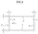
- the print area 20 is set, as shown in Figure 3, with predetermined top, bottom, left, and right margins T, B, L, R which extend beyond the top, bottom, left, and right edges 15, 18, 16, 17 of a sheet, respectively.
- ink discharged on the top, bottom, left, and right margins T, B, L, and R of the print area 20 by the inkjet nozzles 4a is discharged on the base frame 12, causing the problem of contaminating the bottom surface of a sheet passing over the base frame 12.
- the print area margins T, B, L, R are generally set in the range of 2-3mm which means that ink is unnecessarily discharged on the print area margins T, B, L, R, which increases the amount of ink consumed, thereby increasing printer maintenance costs.
- An inkjet printer is characterised in that the paper edge detecting apparatus comprises on-carrier paper edge sensing means disposed on the carrier fixed relative to the printer head, the control means being configured to start operation of the printer head in dependence on a margin width control signal and the output of the on-carrier paper edge sensing means.
- the paper edge sensing apparatus capable of improving the degree of precision in sensing paper edges such as a top edge, a bottom edge, a left edge, and a right edge in a borderless printing mode so as to reduce the print margins in which ink is discharged, thereby reducing ink pollution and consumption due to the unnecessary discharging of ink, is provided.
- the on-carrier paper edge sensing means comprises an optical sensor.
- the apparatus comprises off-carrier paper edge sensing means disposed upstream of the carrier relative to a sheet conveying direction. More preferably, the off-carrier paper edge sensing means comprises a lever positioned to be pivoted by a sheet being conveyed to the printer head. Still more preferably, the control means is configured to determine respective prospective print start times in dependence on the outputs of the on-carrier paper edge sensing means and the off-carrier paper edge sensing means, and to control printer head in accordance with the later of the two prospective print start times.
- the inkjet printer 100 is provided with a base frame 112, a pickup unit (not shown) for picking up sheets of paper P loaded in a paper supply unit (not shown), a sheet conveying unit 103, 103a for conveying a sheet picked up by the pickup unit, a print unit 110 provided with a printer head 104 having inkjet nozzles 104a for forming images on a sheet P conveyed by the sheet conveying unit 103, 103a and a carrier 114 in which the printer head 104 is mounted.
- a pickup unit for picking up sheets of paper P loaded in a paper supply unit (not shown)
- a sheet conveying unit 103, 103a for conveying a sheet picked up by the pickup unit
- a print unit 110 provided with a printer head 104 having inkjet nozzles 104a for forming images on a sheet P conveyed by the sheet conveying unit 103, 103a and a carrier 114 in which the printer head 104 is mounted.
- the sheet conveying unit 103, 103a is provided with a conveying roller 103 for conveying a sheet of paper P picked up by the pickup unit, and a pressure roller 103a for pressing the conveying roller 103 with a predetermined pressure so as to grip the sheet of paper P.
- the carrier 114 is supported by a carrier shaft 115 so that it can move left and right during printing.
- the paper edge sensing apparatus 106 for borderless printing includes a first paper sensor 107 disposed between the pickup unit and the sheet conveying unit 103, 103a to detect the top and bottom edges 15, 18 (see Figure 3) of a sheet of paper P, a second paper sensor 111 installed a predetermined distance D, for example, a distance of 0.5-1mm, upstream from a print position of the inkjet nozzles 104a relative to a paper conveying direction A in order to detect paper edges 15, 18, 16, 19, and a controller 120 for controlling the operation of the inkjet nozzles 104a of the printer head 104 in response to signals from the first and second paper sensors 107, 111 in order to control the top, bottom, left, and right margins T, B, L, and R of a print area 20.
- a predetermined distance D for example, a distance of 0.5-1mm
- the first paper sensor 107 comprises an optical sensor 108 having a light emitter for emitting light and a light receiver for receiving light and a sensor actuator 109 which is rotatably mounted to the base frame 112 on an axis that is perpendicular to the paper conveying direction A.
- the first paper sensor 107 detects the top and bottom edges 15, 18 of a sheet of paper P moving in the paper conveying direction A and transmits first top edge and bottom edge detection signals to the controller 120.
- the controller 120 switches power from the pickup unit to the sheet conveying unit 103, 103a when the first top edge detection signal is generated, compares the first top edge and bottom edge detection signals with second top edge and bottom edge detection signals from the second paper sensor 111, which also detects the top and bottom edges 15, 18, and controls the print start and print end times between which a sheet of paper is printed by the inkjet nozzles 104a of the printer head 104.
- the second paper sensor 111 comprises an optical sensor 116 having a light emitter mounted in the carrier 114 to emit light, a light receiver for receiving light and a reflection surface 113 on the base frame 112 to reflect light emitted from the light emitter to the light receiver.
- the reflection surface 113 extends perpendicularly and longitudinally with respect to the paper conveying direction A.
- the second paper sensor 111 detects the top and bottom edges 15, 18 and the left and right edges 16, 17 of the sheet P and transmits second top and bottom edge detection signals and left and right edge detection signals to the controller 120.
- the controller 120 identifies the signals transmitted from the second paper sensor 111 as detection signals corresponding to the respective edges 15, 16, 17, 18 in dependence on the position of the carrier 114.
- the controller identifies the signal as a signal indicating the position of the top edge 15 or bottom edge 18 of a sheet, and if a detection signal is generated when the carrier 114 is located beyond the left and right edges 16, 17, the controller identifies the detection signal as indicating the position of the left edge 16 or right edge 17 of the sheet.
- the controller 120 compares the first and second top and bottom edge detection signals, generated in respect of the top edge 15 or bottom edge 18 of a sheet P detected by the first and second sheet detection sensors 107, 111, and determines the print start time and the print end time.
- the print start time is set as the later of the estimated time of the top edge 15 reaching the print position of the inkjet nozzles 104a based on the first edge detection signal and the speed of the paper moving through the printer, and the time at which the second top edge detection signal of the second paper sensor 111 occurs.
- the print end time is set to the later of the estimated time that the bottom edge 18 moves past the print position based on the first bottom edge detection signal and the speed of the paper, and the time at which the second bottom edge detection signal of the second paper detection sensor 111 occurs.
- the portions of the top and bottom margins T, B of the print area 20 in which ink is discharged on the base frame 112 can be restricted to at least a distance D, between the print position and the second paper sensor 111, from the top and bottom edges 15, 18 of the sheet.
- D preferably lies in the range 0.5-1mm.
- the left and right margins L, R of the print area 20 are also set to be less than a value which lies in the range of 0.5-1mm from the left and right edges 16, 17.
- the left and right edges 16, 17 of a sheet P can be detected every time the carrier 114 moves beyond a side edge of a sheet P.
- the widths of the left and right margins L, R are the same along the entire length of the sheet P, the edges are only detected once, just after the top edge 15 is detected.
- a paper edge sensing method using a paper edge sensing apparatus 106 for borderless printing according to the present invention as described above will be described in detail below with reference to Figure 4 and Figure 5.
- the optical sensor 108 When the sensor actuator 109 of the first paper sensor 107 is moved (as shown by the dotted lines of Figure 4) by the leading edge 15 of the sheet P, the optical sensor 108 generates a first top edge detection signal (S2), and a driving motor rotates in a reverse direction such that the conveying roller 103 is rotated in a sheet conveying direction A, thus conveying the sheet to the base frame 112.
- S2 first top edge detection signal
- the controller 120 starts counting a period of time after the optical sensor 108 generates the first top edge detection signal (S3).
- the second paper sensor 111 mounts upstream of the inkjet nozzles 104a relative to the paper conveying direction A, the second paper sensor 111 generates the second top edge detection signal (S4).
- the controller 120 estimates the period of time it takes the top edge 15 to move to the print position by counting the time from when the top edge 15 is detected by the first paper sensor 107, compares the estimated time and the time at which the second top edge detection signal occurs, and generates a print start command based on the time which occurs later.
- the inkjet nozzles 104a of the printer head 104 discharge ink at a position spaced by the top print margin T from the top edge 15 of the sheet P, whilst the printer head 104 is moved left and right by the carrier 114 along the carrier shaft 115 in accordance with the command of the controller 120 (S5).
- the controller 120 when the inkjet printer 100 operates in a general print mode (not shown), in which borders are placed on the sheet, the controller 120 generates a print command after a period of time has elapsed during which the sheet P moves by a distance equal to the border width based on only the first or second top edge detection signal detected by the first or second paper sensor 107 or 111.
- the carrier 114 moves left and right causing the second paper sensor 111 to move beyond the left or right edge 16 or 17 of the sheet P, such that the optical sensor 116 of the second paper sensor 111 receives light reflected from the reflection surface 113, and the second paper sensor 111 generates a left or a right edge detection signal (S6).
- the controller 120 determines whether the printer is operating in the borderless print mode. When in the borderless print mode, the controller 120 controls the inkjet nozzles 104a to discharge ink up to a distance corresponding to the predetermined left or the right margin L or R away from the left or the right edge 16 or 17 of the sheet (S7).
- the controller 120 compares the width of the left or the right print margin L or R with data from an encoder, which detects the amount by which the carrier 114 moves.
- the first paper sensor 107 generates a first bottom edge detection signal (S8).
- the controller 120 starts counting the amount of time that elapses after the optical sensor 108 generates the first bottom edge detection signal (S9) in order to estimate the point at which the bottom edge 18 of the paper moves beyond the print position.
- the second paper sensor 111 generates a second bottom edge detection signal in response to receiving light reflected from the reflection surface 113 (S10).
- the controller 120 compares the elapsed time obtained by counting the period of time after the first bottom edge detection signal is received from the first paper sensor 107, during which the sheet moves beyond the print position, with the time at which the controller receives the second bottom edge detection signal.
- the controller generates the print end command based on the time that occurs later (S11).
- the controller 120 leaves a bottom border on the sheet in accordance with the first bottom edge detection signal of the first paper sensor 107 and generates the print end command.
- the printed sheet is externally discharged from the printer by the paper discharge roller (not shown) and the star wheel (not shown) of the paper discharge unit.
- the paper edge sensing apparatus and method of borderless printing described above can improve the degree of precision in sensing paper edges such as the top edge, bottom edge, left edge, and right edge in a borderless printing mode to reduce the printing margins in which the printer head discharges ink, thereby reducing ink pollution and consumption due to the unnecessary discharging of ink.
Landscapes
- Ink Jet (AREA)
- Accessory Devices And Overall Control Thereof (AREA)
- Handling Of Sheets (AREA)
Abstract
Description
Claims (25)
- An inkjet printer having a printer head (104) mounted on a carrier (114), control means (120) and a paper edge detecting apparatus, characterised in that the paper edge detecting apparatus comprises on-carrier paper edge sensing means (111) disposed on the carrier (114) fixed relative to the printer head (104), the control means (120) being configured to start operation of the printer head (104) in dependence on a margin width control signal and the output of the on-carrier paper edge sensing means (111).
- An apparatus according to claim 1, wherein the on-carrier paper edge sensing means (111) comprises an optical sensor (116, 113).
- An apparatus according to claim 1 or 2, comprising off-carrier paper edge sensing means (107) disposed upstream of the carrier (114) relative to a sheet conveying direction.
- An apparatus according to claim 3, wherein the off-carrier paper edge sensing means (107) comprises a lever (109) positioned to be pivoted by a sheet being conveyed to the printer head (104).
- An apparatus according to claim 3 or 4, wherein the control means (120) is configured to determine respective prospective print start times in dependence on the outputs of the on-carrier paper edge sensing means (111) and the off-carrier paper edge sensing means (107), and to control printer head (104) in accordance with the later of the two prospective print start times.
- A paper edge sensing apparatus in a printer, comprising:wherein a paper print margin comprises the predetermined distance between the first paper sensor and the printer head.a carrier;a printer head mounted to the carrier;a first paper sensor mounted to the carrier a predetermined distance from the printer head; anda controller controlling operations of the printer head according to a signal from the first paper sensor; and
- The apparatus of claim 6, wherein the first paper sensor comprises:an optical sensor mounted in the carrier and having a light emitter emitting light, a light receiver receiving light, and a reflection surface to reflect light emitted from the light emitter to the light receiver.
- The apparatus of claim 7, wherein the reflection surface is transversely arranged across a paper convey direction.
- The apparatus of claim 6, wherein the paper print margin includes a top, bottom, left, and right print margin spaced a predetermined distance from a top, bottom, left, and right edge of a sheet of paper, respectively.
- The apparatus of claim 9, wherein the predetermined distance is in a range between 0.5 to 1mm.
- The apparatus of claim 6, further comprising:a second paper sensor mounted between a pickup unit and the convey unit to detect a top edge and a bottom edge of a sheet of paper.
- The apparatus of claim 11, wherein the second paper sensor comprises an optical sensor provided with a light emitter emitting light, a light receiver receiving light, and a sensor actuator rotatably mounted to the frame.
- The apparatus of claim 6, further comprising:an encoder detecting a movement amount of the carrier.
- A paper edge sensing method in a printer having a first paper sensor mounted in a fixed position relative to a moving printer head, comprising:detecting a top edge or a bottom edge of a sheet of paper using the first paper sensor to output a corresponding first top edge detection signal or a first bottom edge detection signal; andgenerating a begin print command when the top edge is detected and an end print command when the bottom edge is detected.
- The method of claim 14, wherein the printer comprises a second paper sensor disposed between a pickup unit and a convey unit and further comprising:wherein the generating includes generating the begin print command at the later of the begin print time interval or the top edge first detection signal and the end print command at the later of the end print time interval or the bottom edge first detection signal.detecting the top or the bottom edge of the sheet using the second paper sensor;begin counting a start print time interval or an end print time interval upon detection of the top or the bottom edge, respectively; and
- The method of claim 15, wherein the printer comprises a controller and the method further comprises:transmitting the first top edge detection signal and the first bottom edge detection signal to the controller;counting the start print time interval and the end print time interval using the controller;comparing the start print time interval to the first top edge detection signal and the second print time interval to the first bottom edge detection signal using the controller; andcontrolling operation of the printer head based on a command from the controller.
- The method of claim 14, wherein the printer comprises a pickup unit and a convey unit and further comprising:controlling dynamic power switching from the pickup unit to the convey unit with the controller.
- The method of claim 14, further comprising:detecting a left edge or a right edge of the sheet of paper when the first paper sensor moves transversely to the left edge or the right edge of the sheet of paper.
- The method of claim 14, the printer comprising the first paper sensor and the printer head mounted to a movable carrier and the method further comprising:identifying a first detection signal as either of the first top edge detection signal or the first bottom edge detection signal if the first detection signal is generated when the carrier is located at an initial position in a central portion of a width of a sheet.
- The method of claim 14, the printer comprising the first paper sensor and the printer head mounted to a movable carrier and the method further comprising:identifying a first detection signal as either a first right edge detection signal or a first left edge detection signal if the first detection signal is generated when the carrier is located outside of an initial position in a central portion of a width of the sheet.
- The method of claim 14, the printer comprising a pickup unit and further comprising:picking up the sheet to print thereon.
- The method of claim 14, further comprising:selecting a general print mode to place margins on the sheet.
- The method of claim 14, further comprising:selecting a borderless print mode such that no margins are placed on the sheet.
- The method of claim 14, further comprising:tracking a position of the first paper sensor.
- The method of claim 14, further comprising:externally discharging an image-printed sheet from the printer.
Applications Claiming Priority (2)
| Application Number | Priority Date | Filing Date | Title |
|---|---|---|---|
| KR2002046356 | 2002-08-06 | ||
| KR10-2002-0046356A KR100449019B1 (en) | 2002-08-06 | 2002-08-06 | apparatus and method for sensing edges of paper in borderless printing mode |
Publications (2)
| Publication Number | Publication Date |
|---|---|
| EP1388422A2 true EP1388422A2 (en) | 2004-02-11 |
| EP1388422A3 EP1388422A3 (en) | 2006-03-15 |
Family
ID=30439419
Family Applications (1)
| Application Number | Title | Priority Date | Filing Date |
|---|---|---|---|
| EP03254701A Withdrawn EP1388422A3 (en) | 2002-08-06 | 2003-07-28 | Paper edge sensing apparatus |
Country Status (4)
| Country | Link |
|---|---|
| US (1) | US7131782B2 (en) |
| EP (1) | EP1388422A3 (en) |
| KR (1) | KR100449019B1 (en) |
| CN (1) | CN1257804C (en) |
Cited By (6)
| Publication number | Priority date | Publication date | Assignee | Title |
|---|---|---|---|---|
| EP1707392A1 (en) * | 2005-03-29 | 2006-10-04 | Brother Kogyo Kabushiki Kaisha | Image recording device with paper skip correction means |
| WO2006084614A3 (en) * | 2005-02-08 | 2006-11-30 | Durst Phototechnik Ag | Inkjet printing device and method for printing multi-coloured images |
| EP2008832A1 (en) | 2007-06-28 | 2008-12-31 | Canon Finetech Inc. | Printing apparatus and printing method |
| EP1851056A4 (en) * | 2005-02-23 | 2010-04-21 | Ricoh Kk | Image forming device |
| WO2013131754A1 (en) * | 2012-03-09 | 2013-09-12 | Oce-Technologies B.V. | Method for full bleed printing |
| US10272699B2 (en) | 2015-12-21 | 2019-04-30 | Hewlett-Packard Development Company, L.P. | Initiating a shortage model |
Families Citing this family (27)
| Publication number | Priority date | Publication date | Assignee | Title |
|---|---|---|---|---|
| EP1434422B1 (en) * | 2001-09-12 | 2012-05-30 | Seiko Epson Corporation | Composite printer and scan image copying method |
| US7742198B2 (en) * | 2001-09-12 | 2010-06-22 | Seiko Epson Corporation | Image processing apparatus and method |
| CN100343069C (en) * | 2002-02-21 | 2007-10-17 | 精工爱普生株式会社 | Printer, method of determining lower end of printed body, computer program and computer system |
| JP3753718B2 (en) * | 2003-08-18 | 2006-03-08 | シャープ株式会社 | Sheet feeding apparatus, image reading apparatus, and image forming apparatus |
| US7410317B2 (en) * | 2003-08-26 | 2008-08-12 | Oki Data Corporation | Method for processing medium, image processing apparatus, and printer apparatus |
| US7391043B2 (en) * | 2004-01-30 | 2008-06-24 | Zih Corp. | Self calibrating media edge sensor |
| JP2005298114A (en) * | 2004-04-09 | 2005-10-27 | Seiko Epson Corp | Printing apparatus, medium detection apparatus, medium detection method, actual measurement method, program, and printing system |
| US20060023047A1 (en) * | 2004-07-30 | 2006-02-02 | James Green | Methods and system for identifying a print medium in a consumables cartridge having a pre-printed border thereon |
| US20060072953A1 (en) * | 2004-10-04 | 2006-04-06 | Daniel Vienneau | Ticket presenter for use with a ticket printer having a tear bar therein |
| KR20060058943A (en) * | 2004-11-26 | 2006-06-01 | 삼성전자주식회사 | Image forming apparatus and method |
| KR101123689B1 (en) * | 2005-09-26 | 2012-03-15 | 삼성전자주식회사 | Apparatus for calculating margin of printing paper and method of the same |
| WO2007046309A1 (en) * | 2005-10-20 | 2007-04-26 | Ricoh Company, Ltd. | Image forming apparatus |
| JP4207955B2 (en) * | 2005-12-27 | 2009-01-14 | ブラザー工業株式会社 | Inkjet recording device |
| JP4961899B2 (en) * | 2006-08-29 | 2012-06-27 | ブラザー工業株式会社 | Image forming apparatus |
| JP5485987B2 (en) * | 2008-06-06 | 2014-05-07 | フジフィルム ディマティックス, インコーポレイテッド | Object detection for printing |
| WO2009152141A2 (en) | 2008-06-09 | 2009-12-17 | Sustainx, Inc. | System and method for rapid isothermal gas expansion and compression for energy storage |
| JP2012062184A (en) * | 2010-09-17 | 2012-03-29 | Seiko Epson Corp | Medium processing device and method of controlling the same |
| CN104002564B (en) * | 2013-02-26 | 2016-03-16 | 星云电脑股份有限公司 | Printing material boundary detection method for large UV inkjet printer |
| JP5843808B2 (en) * | 2013-05-31 | 2016-01-13 | 京セラドキュメントソリューションズ株式会社 | Sheet conveying apparatus, image reading apparatus, and image forming apparatus |
| JP6562729B2 (en) * | 2015-06-18 | 2019-08-21 | キヤノン株式会社 | Inkjet device |
| DE102015225273B4 (en) * | 2015-12-15 | 2025-10-09 | Jdm Innovation Gmbh | Printer and method for operating a printer |
| WO2018216993A1 (en) * | 2017-05-23 | 2018-11-29 | 이명신 | Printing apparatus for security paper |
| JP2019104254A (en) * | 2019-04-01 | 2019-06-27 | キヤノン株式会社 | Printing device and control method of the same |
| CN110341331A (en) * | 2019-08-07 | 2019-10-18 | 福建星谷信息科技有限公司 | A kind of paper border automation detection and control method of stylus printer |
| JP7439528B2 (en) * | 2020-01-21 | 2024-02-28 | 株式会社リコー | Paper feeding device and image forming device |
| JP7661039B2 (en) * | 2020-02-27 | 2025-04-14 | キヤノン株式会社 | Recording device and control method |
| JP7484263B2 (en) * | 2020-03-18 | 2024-05-16 | ブラザー工業株式会社 | Image recording device, system and program |
Family Cites Families (23)
| Publication number | Priority date | Publication date | Assignee | Title |
|---|---|---|---|---|
| US4573618A (en) * | 1984-07-18 | 1986-03-04 | N.C.A. Co., Ltd. | Apparatus for unrolling and spreading rolled cloth |
| US4759205A (en) * | 1985-05-23 | 1988-07-26 | Ishikawajima-Harima Jukogyo Kabushiki Kaisha | Multi-pass rolling method and multi-path rolling-mill stand for carrying out said method |
| US4741526A (en) * | 1986-01-24 | 1988-05-03 | Brandt, Inc. | Adaptive doubles and length measurement techniques and apparatus therefor for use in sheet handling and counting devices |
| JPS63112186A (en) | 1986-10-30 | 1988-05-17 | Nec Corp | Control of printing by detection of printing paper |
| US4983854A (en) | 1988-09-15 | 1991-01-08 | Brother Kogyo Kabushiki Kaisha | Sheet detection apparatus with reflecting member |
| US5513017A (en) * | 1990-09-28 | 1996-04-30 | Xerox Corporation | Automatic document imaging mode selection system |
| US5192141A (en) * | 1991-05-02 | 1993-03-09 | Tidemark Corporation | Multi-dimensional media printer with media based registration and free edge printing |
| US5870114A (en) | 1992-02-12 | 1999-02-09 | Canon Kabushiki Kaisha | Image recording apparatus with improved conveying system for recording medium |
| US5725211A (en) * | 1995-08-28 | 1998-03-10 | Xerox Corporation | Method and apparatus for registering images on the front and the back of a single sheet of paper |
| US6152631A (en) * | 1996-05-18 | 2000-11-28 | Samsung Electronics Co., Ltd. | Automatic paper sensing technique for an ink jet printer |
| US5678159A (en) * | 1996-06-26 | 1997-10-14 | Xerox Corporation | Sheet registration and deskewing device |
| TWI285671B (en) * | 1998-10-13 | 2007-08-21 | Orion 21 A D Pty Ltd | Luminescent gel coats and moldable resins |
| US6239817B1 (en) * | 1998-10-20 | 2001-05-29 | Hewlett-Packard Comapny | Apparatus and method for printing borderless print image |
| US6029158A (en) * | 1998-12-22 | 2000-02-22 | Ac Properties B.V. | System, method and article of manufacture for a simulation enabled feedback system |
| KR100318734B1 (en) * | 1999-02-22 | 2001-12-28 | 윤종용 | Apparatus for sensing paper of office automated machine |
| JP2001030532A (en) * | 1999-05-19 | 2001-02-06 | Fuji Photo Film Co Ltd | Method and apparatus for forming print image |
| US6352332B1 (en) * | 1999-07-08 | 2002-03-05 | Hewlett-Packard Company | Method and apparatus for printing zone print media edge detection |
| US6467900B1 (en) * | 2000-02-14 | 2002-10-22 | Lexmark International, Inc. | Printzone media sensor for inkjet printer |
| US6435641B1 (en) | 2000-08-30 | 2002-08-20 | Hewlett-Packard Company | Media movement apparatus |
| US6447089B1 (en) * | 2000-10-13 | 2002-09-10 | Hewlett-Packard Company | Techniques for using a linear array to detect media top/bottom edges for full bleed printing |
| US6496211B2 (en) * | 2000-11-13 | 2002-12-17 | Fuji Photo Film Co., Ltd. | Thermal printer and thermal printing method |
| CN2460300Y (en) | 2000-11-28 | 2001-11-21 | 北京智凯办公自动化设备有限公司 | Typewriter with testing edge of printing medium |
| US6523925B1 (en) * | 2001-10-30 | 2003-02-25 | Hewlett-Packard Company | Media leading edge sensor |
-
2002
- 2002-08-06 KR KR10-2002-0046356A patent/KR100449019B1/en not_active Expired - Fee Related
-
2003
- 2003-06-25 US US10/602,631 patent/US7131782B2/en not_active Expired - Fee Related
- 2003-07-28 EP EP03254701A patent/EP1388422A3/en not_active Withdrawn
- 2003-08-05 CN CNB031525598A patent/CN1257804C/en not_active Expired - Fee Related
Cited By (14)
| Publication number | Priority date | Publication date | Assignee | Title |
|---|---|---|---|---|
| US8764148B2 (en) | 2005-02-08 | 2014-07-01 | Durst Phototechnik—A.G. | Inkjet printing device and method for printing multi-colored images |
| WO2006084614A3 (en) * | 2005-02-08 | 2006-11-30 | Durst Phototechnik Ag | Inkjet printing device and method for printing multi-coloured images |
| EP2100739A3 (en) * | 2005-02-08 | 2009-11-04 | Durst Phototechnik A.G. | Ink jet printing device and method for printing multi-colour images |
| US8141981B2 (en) | 2005-02-08 | 2012-03-27 | Durst Phototechnik - A.G. | Inkjet printing device and method for printing multi-coloured images |
| EP1851056A4 (en) * | 2005-02-23 | 2010-04-21 | Ricoh Kk | Image forming device |
| EP1707392A1 (en) * | 2005-03-29 | 2006-10-04 | Brother Kogyo Kabushiki Kaisha | Image recording device with paper skip correction means |
| US8944544B2 (en) | 2007-06-28 | 2015-02-03 | Canon Finetech, Inc. | Printing apparatus and printing method |
| EP2754562A1 (en) * | 2007-06-28 | 2014-07-16 | Canon Finetech Inc. | Printing apparatus and printing method |
| EP2008832A1 (en) | 2007-06-28 | 2008-12-31 | Canon Finetech Inc. | Printing apparatus and printing method |
| WO2013131754A1 (en) * | 2012-03-09 | 2013-09-12 | Oce-Technologies B.V. | Method for full bleed printing |
| US9120342B2 (en) | 2012-03-09 | 2015-09-01 | Oce-Technologies B.V. | Method for full bleed printing |
| US10272699B2 (en) | 2015-12-21 | 2019-04-30 | Hewlett-Packard Development Company, L.P. | Initiating a shortage model |
| EP3313667A4 (en) * | 2015-12-21 | 2019-06-12 | Hewlett-Packard Development Company, L.P. | INITIATION OF A SHORTAGE MODEL |
| US10723149B2 (en) | 2015-12-21 | 2020-07-28 | Hewlett-Packard Development Company, L.P. | Initiating a shortage model |
Also Published As
| Publication number | Publication date |
|---|---|
| CN1480336A (en) | 2004-03-10 |
| US20040028450A1 (en) | 2004-02-12 |
| KR100449019B1 (en) | 2004-09-18 |
| CN1257804C (en) | 2006-05-31 |
| KR20040013431A (en) | 2004-02-14 |
| EP1388422A3 (en) | 2006-03-15 |
| US7131782B2 (en) | 2006-11-07 |
Similar Documents
| Publication | Publication Date | Title |
|---|---|---|
| EP1388422A2 (en) | Paper edge sensing apparatus | |
| US7262786B2 (en) | Image aligning method for thermal imaging printer | |
| EP2138317B1 (en) | Printing apparatus and object conveyance control method | |
| US8142087B2 (en) | Printing device with paper width detector mounted to carriage and method of controlling the printing device | |
| US20070091132A1 (en) | Apparatus to automatically adjust nozzles used, image forming apparatus having the same, and method of automatically adjusting nozzles used | |
| JP5217737B2 (en) | Paper width detection method for label printer, printing control method for label printer, and label printer | |
| US7681974B2 (en) | Recording apparatus and method | |
| US7417657B2 (en) | Thermal printer and printing method | |
| CN101112831A (en) | Printer and printing method | |
| US20070055724A1 (en) | Method of obtaining correction value of optical sensor and recording apparatus | |
| JP2011121271A (en) | Recording method | |
| US7333122B2 (en) | Method of printing thermal media by aligning image | |
| JP5309767B2 (en) | Paper width detection method for label printer, printing control method for label printer, and label printer | |
| US8817256B2 (en) | Medium-pressing device and malfunction detection method for detecting malfunction based on displacement in power supply | |
| US7250958B2 (en) | Method of printing thermal media by aligning image | |
| US20060044381A1 (en) | Printer | |
| US20080080920A1 (en) | Printer and method of controlling printer | |
| US7591602B2 (en) | Gap detector, liquid ejecting apparatus incorporating the same, and gap detecting method executed in the apparatus | |
| JP7459650B2 (en) | Liquid discharge device and liquid discharge method | |
| JPH11208928A (en) | Paper width detection mechanism of ink jet printer | |
| JP4492147B2 (en) | Ink jet recording apparatus and recording medium movement control method | |
| US20080278526A1 (en) | Ink jet printer with expanded validation print zone | |
| KR100477691B1 (en) | Inkjet printer being capable of borderless printing | |
| JPH0524224A (en) | Paper compatibility judging device in thermal transfer printer | |
| JP2007050985A (en) | Continuous paper processing apparatus and operation control method |
Legal Events
| Date | Code | Title | Description |
|---|---|---|---|
| PUAI | Public reference made under article 153(3) epc to a published international application that has entered the european phase |
Free format text: ORIGINAL CODE: 0009012 |
|
| AK | Designated contracting states |
Kind code of ref document: A2 Designated state(s): AT BE BG CH CY CZ DE DK EE ES FI FR GB GR HU IE IT LI LU MC NL PT RO SE SI SK TR |
|
| AX | Request for extension of the european patent |
Extension state: AL LT LV MK |
|
| RAP1 | Party data changed (applicant data changed or rights of an application transferred) |
Owner name: SAMSUNG ELECTRONICS CO., LTD. |
|
| PUAL | Search report despatched |
Free format text: ORIGINAL CODE: 0009013 |
|
| AK | Designated contracting states |
Kind code of ref document: A3 Designated state(s): AT BE BG CH CY CZ DE DK EE ES FI FR GB GR HU IE IT LI LU MC NL PT RO SE SI SK TR |
|
| AX | Request for extension of the european patent |
Extension state: AL LT LV MK |
|
| 17P | Request for examination filed |
Effective date: 20060410 |
|
| AKX | Designation fees paid |
Designated state(s): DE GB NL |
|
| STAA | Information on the status of an ep patent application or granted ep patent |
Free format text: STATUS: THE APPLICATION IS DEEMED TO BE WITHDRAWN |
|
| 18D | Application deemed to be withdrawn |
Effective date: 20100202 |