EP1387958B1 - A pumping system - Google Patents
A pumping system Download PDFInfo
- Publication number
- EP1387958B1 EP1387958B1 EP02738300A EP02738300A EP1387958B1 EP 1387958 B1 EP1387958 B1 EP 1387958B1 EP 02738300 A EP02738300 A EP 02738300A EP 02738300 A EP02738300 A EP 02738300A EP 1387958 B1 EP1387958 B1 EP 1387958B1
- Authority
- EP
- European Patent Office
- Prior art keywords
- drive shaft
- reservoir
- rotation
- clutch
- cam
- Prior art date
- Legal status (The legal status is an assumption and is not a legal conclusion. Google has not performed a legal analysis and makes no representation as to the accuracy of the status listed.)
- Expired - Lifetime
Links
Images


Classifications
-
- F—MECHANICAL ENGINEERING; LIGHTING; HEATING; WEAPONS; BLASTING
- F04—POSITIVE - DISPLACEMENT MACHINES FOR LIQUIDS; PUMPS FOR LIQUIDS OR ELASTIC FLUIDS
- F04B—POSITIVE-DISPLACEMENT MACHINES FOR LIQUIDS; PUMPS
- F04B49/00—Control, e.g. of pump delivery, or pump pressure of, or safety measures for, machines, pumps, or pumping installations, not otherwise provided for, or of interest apart from, groups F04B1/00 - F04B47/00
- F04B49/22—Control, e.g. of pump delivery, or pump pressure of, or safety measures for, machines, pumps, or pumping installations, not otherwise provided for, or of interest apart from, groups F04B1/00 - F04B47/00 by means of valves
- F04B49/24—Bypassing
-
- F—MECHANICAL ENGINEERING; LIGHTING; HEATING; WEAPONS; BLASTING
- F04—POSITIVE - DISPLACEMENT MACHINES FOR LIQUIDS; PUMPS FOR LIQUIDS OR ELASTIC FLUIDS
- F04B—POSITIVE-DISPLACEMENT MACHINES FOR LIQUIDS; PUMPS
- F04B23/00—Pumping installations or systems
- F04B23/02—Pumping installations or systems having reservoirs
- F04B23/021—Pumping installations or systems having reservoirs the pump being immersed in the reservoir
-
- F—MECHANICAL ENGINEERING; LIGHTING; HEATING; WEAPONS; BLASTING
- F04—POSITIVE - DISPLACEMENT MACHINES FOR LIQUIDS; PUMPS FOR LIQUIDS OR ELASTIC FLUIDS
- F04B—POSITIVE-DISPLACEMENT MACHINES FOR LIQUIDS; PUMPS
- F04B35/00—Piston pumps specially adapted for elastic fluids and characterised by the driving means to their working members, or by combination with, or adaptation to, specific driving engines or motors, not otherwise provided for
-
- F—MECHANICAL ENGINEERING; LIGHTING; HEATING; WEAPONS; BLASTING
- F04—POSITIVE - DISPLACEMENT MACHINES FOR LIQUIDS; PUMPS FOR LIQUIDS OR ELASTIC FLUIDS
- F04B—POSITIVE-DISPLACEMENT MACHINES FOR LIQUIDS; PUMPS
- F04B49/00—Control, e.g. of pump delivery, or pump pressure of, or safety measures for, machines, pumps, or pumping installations, not otherwise provided for, or of interest apart from, groups F04B1/00 - F04B47/00
- F04B49/20—Control, e.g. of pump delivery, or pump pressure of, or safety measures for, machines, pumps, or pumping installations, not otherwise provided for, or of interest apart from, groups F04B1/00 - F04B47/00 by changing the driving speed
-
- F—MECHANICAL ENGINEERING; LIGHTING; HEATING; WEAPONS; BLASTING
- F04—POSITIVE - DISPLACEMENT MACHINES FOR LIQUIDS; PUMPS FOR LIQUIDS OR ELASTIC FLUIDS
- F04B—POSITIVE-DISPLACEMENT MACHINES FOR LIQUIDS; PUMPS
- F04B2201/00—Pump parameters
- F04B2201/12—Parameters of driving or driven means
- F04B2201/124—Coupling parameters
-
- F—MECHANICAL ENGINEERING; LIGHTING; HEATING; WEAPONS; BLASTING
- F04—POSITIVE - DISPLACEMENT MACHINES FOR LIQUIDS; PUMPS FOR LIQUIDS OR ELASTIC FLUIDS
- F04B—POSITIVE-DISPLACEMENT MACHINES FOR LIQUIDS; PUMPS
- F04B2201/00—Pump parameters
- F04B2201/12—Parameters of driving or driven means
- F04B2201/124—Coupling parameters
- F04B2201/1241—Engagement
-
- F—MECHANICAL ENGINEERING; LIGHTING; HEATING; WEAPONS; BLASTING
- F04—POSITIVE - DISPLACEMENT MACHINES FOR LIQUIDS; PUMPS FOR LIQUIDS OR ELASTIC FLUIDS
- F04B—POSITIVE-DISPLACEMENT MACHINES FOR LIQUIDS; PUMPS
- F04B2203/00—Motor parameters
- F04B2203/02—Motor parameters of rotating electric motors
- F04B2203/0209—Rotational speed
Definitions
- This invention relates to a pumping system as specified in the preamble of Claim 1.
- a pumping system is known e.g. from WO 99/01338.
- pumping systems designed for two way operation have a fluid return channel to allow fluid to flow back from one fluid store to another.
- the return channel and the pump are controlled independently.
- An example of a control mechanism for a return channel is a solenoid valve, the size of which can be comparable to that of the motor.
- the disadvantage of this arrangement is that incorporation of such a return channel and associated control mechanism greatly increases the size and weight of the pump.
- a pumping system comprises a first reservoir and a second reservoir; a motor coupled to a drive shaft; a pump, driven by the drive shaft, for pumping fluid from the first reservoir to the second reservoir; and by-pass means for controllably returning fluid from the second reservoir to the first reservoir; characterised by a clutch between the drive shaft and the by-pass means whereby rotation of the drive shaft in a first direction drives the pump and disengages the clutch while the by-pass means is closed, and rotation of the drive shaft in a second direction engages the clutch so that the by-pass means is opened.
- the by-pass means operates under control of the drive shaft, thereby removing the need for separate control components and so reducing the size and weight of the pumping system.
- closing the by-pass means when driving the pump maximises the net rate of fluid transfer between the first reservoir and the second reservoir whilst rotation in the second direction allows return of the fluid from the second reservoir to the first reservoir.
- the by-pass means is adapted to be closed when the motor is idle.
- the by-pass means comprises a by-pass valve.
- the by-pass means comprises a cam-follower and a cam; wherein the clutch is operative between the drive shaft and the cam; and whereby opening and closure of the by-pass means is controlled by engagement of the cam-follower with the cam and rotation of the drive shaft.
- the cam comprises an end stop, whereby rotation of the drive shaft in the second direction causes the end stop to reach the cam-follower after the by-pass means is opened, thereby restraining the cam.
- the clutch comprises a flexible resilient sleeve attached to the drive shaft and adapted to grip a shaft operatively associated with the by-pass means when the drive shaft is rotated in the second direction; and whereby rotation of the drive shaft in the first direction causes the sleeve to loosen from the second-mentioned shaft.
- the flexible resilient sleeve comprises a spring.
- the clutch comprises two clutch plates; wherein each clutch plate comprises bevelled teeth; wherein one clutch plate is sprung loaded; whereby rotation of the drive shaft in the first direction allows the bevelled teeth to pass over each other; and whereby rotation of the drive shaft in the second direction causes the bevelled teeth to mesh.
- the by-pass means is housed within the pump.
- the pump comprises a swash plate pump.
- swash plate pump uses a single way valve, so nothing leaks back to the first reservoir when the motor stops rotating. Nor is a gearbox required on the motor, so reducing the size and noise generated in operation.
- Fig. 1 illustrates, schematically, a pumping system according to the invention.
- a motor 1 is coupled to and drives a pump 2 which pumps fluid from a first reservoir 3 to a second reservoir 4.
- a by-pass mechanism 5 controls the return of fluid from the second reservoir to the first reservoir, when motor rotation is reversed assuming higher pressure in the second reservoir.
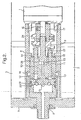
- Fig. 2 shows the pumping system of Fig. 1 in more detail.
- An outer housing 6 of the pumping system is attached to a bulkhead 7 by a threaded mounting spigot 8 and a nut (not shown).
- the first reservoir 3 is provided outside the housing 6 and fluid flows between the first reservoir and the second reservoir 4 via an orifice in the threaded mounted spigot 8.
- the housing 6 contains the pump and the by-pass mechanism.
- the pump comprises a swash plate 9 and two pistons 10, 11 that run in two cylinders 12, 13.
- the swash plate engages the two pistons which move within their respective cylinders.
- the swash plate engages both pistons at diametrically opposed positions on the swash plate and each piston is held against the swash plate by a spring 14, 15 respectively.
- the motor 1 is attached to the housing 6.
- the motor is coupled to a drive shaft 16 which in turn is coupled to the swash plate 9 via a coupling 17.
- the motor drives the swash plate which causes both pistons 10, 11 to oscillate within their respective cylinders 12, 13.
- Figs. 3 and 4 show the motion of the piston 10 within its respective cylinder 12.
- Fig. 3 shows an extreme of oscillation, the engaged position, where the piston is, as far as possible, driven in to the cylinder by the swash plate 9.
- Fig. 4 shows the other extreme of oscillation, the disengaged position, where the piston is, as far as possible, driven out of the cylinder by the spring 14 acting against the piston.
- Figure 5 illustrates actuation of the by-pass mechanism in the pumping system according to the invention.
- the by-pass 5 comprises a cam 21, a cam shaft 22, a cam follower 23, a spring clutch 24 and a by-pass valve 25.
- the by-pass valve is coupled to the cam-follower which engages the cam. Rotation of the cam in a first direction of rotation causes, the by-pass valve to close thereby preventing transfer of fluid from the second reservoir 4 to the first reservoir 3. Rotation of the cam in a second direction of rotation allows return of the fluid from the second reservoir to the first reservoir.
- the camshaft 22 is coupled to the drive shaft 16 via a spring clutch 24. Rotation of the motor 1 in the first direction causes the spring clutch to unwind, causing it to loosen its grip on the camshaft.
- the overall dimensions were 22mm diameter and 62mm length.
- the hydraulic fluid used was 10W40 motor oil which was pumped at up to 30ml per minute at pressures of 48.3 Bar (4.8 MN/m 2 or 700psi).
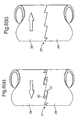
- Figs. 6a and 6b show an alternative clutch arrangement which may be used instead of the spring clutch 24.
- the alternative clutch 27 comprises two clutch plates 28, 29, both of which have bevelled teeth 30, 31.
- the clutch plates are urged together, preferably by spring loading (not shown).
- Fig. 6a shows the operation of the alternative clutch 27 corresponding to rotation of the motor 1 in the first direction of rotation.
- the bevelled teeth 30, 31 do not engage each other, instead they react against the urging force between the clutch plates 28, 27 and allow the clutch plates to run over each other.
- Fig. 6b shows the operation of the alternative clutch 27 corresponding to rotation of the motor 1 in the second direction of rotation. Such rotation causes the bevelled teeth 30, 31 to engage, thereby preventing relative motion between the two clutch plates 28,29.
Landscapes
- Engineering & Computer Science (AREA)
- Mechanical Engineering (AREA)
- General Engineering & Computer Science (AREA)
- Reciprocating Pumps (AREA)
- Details And Applications Of Rotary Liquid Pumps (AREA)
- Eye Examination Apparatus (AREA)
- Fluid-Driven Valves (AREA)
- Control Of Non-Positive-Displacement Pumps (AREA)
Abstract
Description
- This invention relates to a pumping system as specified in the preamble of Claim 1. Such a pumping system is known e.g. from WO 99/01338.
- Conventionally, pumping systems designed for two way operation have a fluid return channel to allow fluid to flow back from one fluid store to another. Generally, the return channel and the pump are controlled independently. An example of a control mechanism for a return channel is a solenoid valve, the size of which can be comparable to that of the motor. The disadvantage of this arrangement is that incorporation of such a return channel and associated control mechanism greatly increases the size and weight of the pump.
- According to the present invention, a pumping system comprises a first reservoir and a second reservoir; a motor coupled to a drive shaft; a pump, driven by the drive shaft, for pumping fluid from the first reservoir to the second reservoir; and by-pass means for controllably returning fluid from the second reservoir to the first reservoir; characterised by a clutch between the drive shaft and the by-pass means whereby rotation of the drive shaft in a first direction drives the pump and disengages the clutch while the by-pass means is closed, and rotation of the drive shaft in a second direction engages the clutch so that the by-pass means is opened.
- In the present invention, the by-pass means operates under control of the drive shaft, thereby removing the need for separate control components and so reducing the size and weight of the pumping system.
- When rotating the drive shaft in the first direction of rotation, closing the by-pass means when driving the pump maximises the net rate of fluid transfer between the first reservoir and the second reservoir whilst rotation in the second direction allows return of the fluid from the second reservoir to the first reservoir. This arrangement is particularly convenient given that motors often exhibit greater torque and power characteristics in one direction of rotation compared to the other.
- Preferably, the by-pass means is adapted to be closed when the motor is idle.
- This allows fluid in the second reservoir to be maintained at a higher pressure than fluid in the first reservoir when the motor is idle.
- Preferably, the by-pass means comprises a by-pass valve.
- Preferably, the by-pass means comprises a cam-follower and a cam; wherein the clutch is operative between the drive shaft and the cam; and whereby opening and closure of the by-pass means is controlled by engagement of the cam-follower with the cam and rotation of the drive shaft.
- Preferably, the cam comprises an end stop, whereby rotation of the drive shaft in the second direction causes the end stop to reach the cam-follower after the by-pass means is opened, thereby restraining the cam.
- In a preferred embodiment, the clutch comprises a flexible resilient sleeve attached to the drive shaft and adapted to grip a shaft operatively associated with the by-pass means when the drive shaft is rotated in the second direction; and whereby rotation of the drive shaft in the first direction causes the sleeve to loosen from the second-mentioned shaft. Conveniently, the flexible resilient sleeve comprises a spring.
- Alternatively, the clutch comprises two clutch plates; wherein each clutch plate comprises bevelled teeth; wherein one clutch plate is sprung loaded; whereby rotation of the drive shaft in the first direction allows the bevelled teeth to pass over each other; and whereby rotation of the drive shaft in the second direction causes the bevelled teeth to mesh.
- Preferably, the by-pass means is housed within the pump.
- Preferably, the pump comprises a swash plate pump.
- One benefit of a swash plate pump is that it uses a single way valve, so nothing leaks back to the first reservoir when the motor stops rotating. Nor is a gearbox required on the motor, so reducing the size and noise generated in operation.
- An example of a pumping system according to the invention will now be described with reference to the accompanying drawings in which:
- Figure 1 illustrates, schematically, a pumping system according to the present invention;
- Figure 2 illustrates the pumping system of Fig. 1 in more detail;
- Figures 3 and 4 illustrate the motion of a piston within its respective cylinder in the pumping system of Fig 1;
- Figure 5 illustrates by-pass actuation in the example of Fig. 1;
- Figure 6 shows an alternative clutch arrangement.
- Fig. 1 illustrates, schematically, a pumping system according to the invention. A motor 1 is coupled to and drives a
pump 2 which pumps fluid from afirst reservoir 3 to a second reservoir 4. A by-pass mechanism 5 controls the return of fluid from the second reservoir to the first reservoir, when motor rotation is reversed assuming higher pressure in the second reservoir. - Fig. 2 shows the pumping system of Fig. 1 in more detail. An
outer housing 6 of the pumping system is attached to a bulkhead 7 by a threaded mounting spigot 8 and a nut (not shown). Thefirst reservoir 3 is provided outside thehousing 6 and fluid flows between the first reservoir and the second reservoir 4 via an orifice in the threaded mounted spigot 8. Thehousing 6 contains the pump and the by-pass mechanism. The pump comprises aswash plate 9 and twopistons cylinders spring - The motor 1 is attached to the
housing 6. The motor is coupled to adrive shaft 16 which in turn is coupled to theswash plate 9 via acoupling 17. The motor drives the swash plate which causes bothpistons respective cylinders - Figs. 3 and 4 show the motion of the
piston 10 within itsrespective cylinder 12. Fig. 3 shows an extreme of oscillation, the engaged position, where the piston is, as far as possible, driven in to the cylinder by theswash plate 9. Fig. 4 shows the other extreme of oscillation, the disengaged position, where the piston is, as far as possible, driven out of the cylinder by thespring 14 acting against the piston. - From the disengaged position, movement or the
piston 10 towards the engaged position causes the piston to compress fluid within thecylinder 12, the fluid having been received from thefirst reservoir 3 via aninlet 18. Once the piston has moved past the inlet, the fluid within the cylinder is discharged to the second reservoir 4, via anoutlet 19 and anon-return valve 20. From the engaged position, movement of the piston towards the disengaged position, whereby the piston is withdrawn past the inlet, allows thecylinder 12 to re-fill with fluid received from the first reservoir. Continuous rotation of theswash plate 9 causes repetition of the engaged and disengaged piston cycle, thereby producing fluid flow from the first reservoir to the second reservoir. - Figure 5 illustrates actuation of the by-pass mechanism in the pumping system according to the invention. The by-pass 5 comprises a
cam 21, acam shaft 22, acam follower 23, aspring clutch 24 and a by-pass valve 25. The by-pass valve is coupled to the cam-follower which engages the cam. Rotation of the cam in a first direction of rotation causes, the by-pass valve to close thereby preventing transfer of fluid from the second reservoir 4 to thefirst reservoir 3. Rotation of the cam in a second direction of rotation allows return of the fluid from the second reservoir to the first reservoir. - The
camshaft 22 is coupled to thedrive shaft 16 via aspring clutch 24. Rotation of the motor 1 in the first direction causes the spring clutch to unwind, causing it to loosen its grip on the camshaft. - In Fig. 5a, initial rotation of the motor 1 in the first direction of rotation causes the
cam 21 to rotate such that thecam follower 23 is retracted and the by-pass valve 25 is closed. Further rotation of the motor in the first direction causes thespring clutch 24 to disengage whereby the cam andcamshaft 22 are restrained by an end stop 25, and continued rotation of the motor is substantially unrestricted. - In Fig. 5b, rotation of the motor 1 in the second direction of rotation causes the
spring clutch 24 to engage thecamshaft 22, thereby rotating thecam 21. This causes the cam-follower 23 to adapt and, as a consequence, open the by-pass valve allowing fluid to flow back from the second reservoir 4 to thefirst reservoir 3. The valve remains open until pump rotation is reversed. - In one example of a system according to the invention, the overall dimensions were 22mm diameter and 62mm length. The hydraulic fluid used was 10W40 motor oil which was pumped at up to 30ml per minute at pressures of 48.3 Bar (4.8 MN/m2 or 700psi).
- Figs. 6a and 6b show an alternative clutch arrangement which may be used instead of the
spring clutch 24. Thealternative clutch 27 comprises twoclutch plates teeth bevelled teeth clutch plates - Fig. 6b shows the operation of the alternative clutch 27 corresponding to rotation of the motor 1 in the second direction of rotation. Such rotation causes the bevelled
teeth clutch plates
Claims (10)
- A pumping system comprising a first reservoir (3) and a second reservoir (4), a motor (1) coupled to a drive shaft (16); a pump (2), driven by the drive shaft (16), for pumping fluid from the first reservoir (3) to the second reservoir (4) and by-pass means (5) for controllably returning fluid from the second reservoir (4) to the first reservoir (3): characterised by a clutch (24;27) between the drive shaft (16) and the by-pass means (5) whereby rotation of the drive shaft (16) in a first direction drives the pump (2) and disengages the clutch (24;27) while the by-pass means (5) is closed, and rotation of the drive shaft (16) in a second direction engages the clutch (24;27) so that the by-pass means (5) is opened.
- A system according to claim 1, wherein the by-pass means (5) is adapted to be closed when the motor (1) is idle.
- A system according to claim 1 or claim 2, wherein the by-pass means (5) comprises a by-pass valve (25).
- A system according to any preceding claim, wherein the by-pass means (5) comprises a cam-follower (23) and a cam (21); wherein the clutch (24;27) is operative between the drive shaft (16) and the cam (21); and whereby opening and closure of the means is controlled by engagement of the cam-follower (23) with the cam (21) and rotation of the drive shaft (16).
- A system according to claim 4 wherein the cam (21) comprises an end stop (26), whereby rotation of the drive shaft (15) in the second direction causes the end stop (26) to reach the cam-follower (23) after the by-pass means (5) is opened, thereby restraining the cam (21).
- A system according to any preceding claim, wherein the clutch comprises a flexible resilient sleeve (24) attached to the drive shaft (16) and adapted to grip a shaft (22) operatively associated with the by-pass means (5) when the drive shaft (16) is rotated in the second direction; and whereby rotation of the drive shaft (16) in the first direction causes the sleeve (24) to loosen from the second-mentioned shaft (22).
- A system according to claim 6, wherein the flexible resilient sleeve comprises a spring (24).
- A system according to any one of claims 1 to 5, wherein the clutch comprises two clutch plates (28,29); wherein each clutch plate (28,29) comprises bevelled teeth (30,31); wherein at least one clutch plate is sprung loaded; whereby rotation of the drive shaft (16) in the first direction allows the bevelled teeth (30,31) to pass over each other and whereby rotation of the drive shaft (16) in the second direction causes the bevelled teeth (30,31) to mesh.
- A system according to any preceding claim, wherein the by-pass means (5) is housed within the pump (2).
- A system as claimed in any preceding claim wherein the pump (2) comprises a swash plate pump.
Applications Claiming Priority (3)
| Application Number | Priority Date | Filing Date | Title |
|---|---|---|---|
| GB0111823A GB2375572A (en) | 2001-05-15 | 2001-05-15 | A pumping system with bypass means |
| GB0111823 | 2001-05-15 | ||
| PCT/GB2002/002126 WO2002093012A1 (en) | 2001-05-15 | 2002-05-13 | A pumping system |
Publications (2)
| Publication Number | Publication Date |
|---|---|
| EP1387958A1 EP1387958A1 (en) | 2004-02-11 |
| EP1387958B1 true EP1387958B1 (en) | 2006-10-11 |
Family
ID=9914652
Family Applications (1)
| Application Number | Title | Priority Date | Filing Date |
|---|---|---|---|
| EP02738300A Expired - Lifetime EP1387958B1 (en) | 2001-05-15 | 2002-05-13 | A pumping system |
Country Status (6)
| Country | Link |
|---|---|
| US (1) | US7033143B2 (en) |
| EP (1) | EP1387958B1 (en) |
| AT (1) | ATE342445T1 (en) |
| DE (1) | DE60215334D1 (en) |
| GB (1) | GB2375572A (en) |
| WO (1) | WO2002093012A1 (en) |
Families Citing this family (1)
| Publication number | Priority date | Publication date | Assignee | Title |
|---|---|---|---|---|
| AU2021339466A1 (en) * | 2020-09-09 | 2023-05-25 | Y&R Allum Pty Ltd | Balanced piston pump for subsea use |
Family Cites Families (3)
| Publication number | Priority date | Publication date | Assignee | Title |
|---|---|---|---|---|
| GB924674A (en) * | 1959-05-08 | 1963-05-01 | Lucas Industries Ltd | Fuel pumps |
| US6179574B1 (en) * | 1997-01-22 | 2001-01-30 | Jetec Company | Apparatus for pressurizing fluids and using them to perform work |
| GB9713973D0 (en) * | 1997-07-03 | 1997-09-10 | Secr Defence | Depth control device |
-
2001
- 2001-05-15 GB GB0111823A patent/GB2375572A/en not_active Withdrawn
-
2002
- 2002-05-13 DE DE60215334T patent/DE60215334D1/en not_active Expired - Lifetime
- 2002-05-13 EP EP02738300A patent/EP1387958B1/en not_active Expired - Lifetime
- 2002-05-13 WO PCT/GB2002/002126 patent/WO2002093012A1/en not_active Ceased
- 2002-05-13 AT AT02738300T patent/ATE342445T1/en not_active IP Right Cessation
- 2002-05-13 US US10/476,822 patent/US7033143B2/en not_active Expired - Fee Related
Also Published As
| Publication number | Publication date |
|---|---|
| DE60215334D1 (en) | 2006-11-23 |
| EP1387958A1 (en) | 2004-02-11 |
| US20040131474A1 (en) | 2004-07-08 |
| GB2375572A (en) | 2002-11-20 |
| ATE342445T1 (en) | 2006-11-15 |
| US7033143B2 (en) | 2006-04-25 |
| GB0111823D0 (en) | 2001-07-04 |
| WO2002093012A1 (en) | 2002-11-21 |
Similar Documents
| Publication | Publication Date | Title |
|---|---|---|
| US5219274A (en) | Pump with internal pressure relief | |
| US5465817A (en) | Hydraulic brake pump with eccentric cam and reciprocating piston | |
| EP0232053A2 (en) | Swash plate type hydraulic system | |
| EP1603711B1 (en) | Impact device with a rotatable control valve | |
| EP0898653B1 (en) | Hydraulic pressure control system for a pump | |
| US9605801B2 (en) | Lubricating grease return valve | |
| KR20180071372A (en) | Hydraulic Pump Control System | |
| CA2585522A1 (en) | Grease gun | |
| CN110030182B (en) | Piston pumps for conveying pressure medium in pressure medium circuits | |
| JPH08512375A (en) | Cyclic hydraulic pump | |
| US7033143B2 (en) | Pumping system with clutch and associated by-pass | |
| US5373921A (en) | Hydraulic gearwheel brake pump | |
| JP2004353533A (en) | Compressor and duckbill valves | |
| WO1995030472A1 (en) | Reverse osmosis permeate pump | |
| RU2536035C2 (en) | Hydromechanical clutch | |
| US4629400A (en) | Hydraulic pump with pistons and controlled suction valves | |
| RU2008130823A (en) | VISIBLE TRANSMISSION | |
| EP0745774B1 (en) | Variable-delivery pump | |
| RU2186270C1 (en) | Hydraulic clutch | |
| RU2172428C1 (en) | Axial-piston pump and vehicle hydraulic transmission with axial- piston pump | |
| KR101861076B1 (en) | Apparatus for controlling the flow rate of pump provided in electric hydrostatic system | |
| EP1191193B1 (en) | Internal combustion engine for motor vehicles and the like | |
| SU802669A1 (en) | Inertial pulser | |
| GB2366601A (en) | Pump arrangement within a drive shaft | |
| JP3290607B2 (en) | Valves and pistons with valves |
Legal Events
| Date | Code | Title | Description |
|---|---|---|---|
| PUAI | Public reference made under article 153(3) epc to a published international application that has entered the european phase |
Free format text: ORIGINAL CODE: 0009012 |
|
| 17P | Request for examination filed |
Effective date: 20031030 |
|
| AK | Designated contracting states |
Kind code of ref document: A1 Designated state(s): AT BE CH CY DE DK ES FI FR GB GR IE IT LI LU MC NL PT SE TR |
|
| AX | Request for extension of the european patent |
Extension state: AL LT LV MK RO SI |
|
| GRAP | Despatch of communication of intention to grant a patent |
Free format text: ORIGINAL CODE: EPIDOSNIGR1 |
|
| RIC1 | Information provided on ipc code assigned before grant |
Ipc: F04B 1/34 20060101ALI20060426BHEP Ipc: F04B 49/035 20060101AFI20060426BHEP Ipc: B63G 8/14 20060101ALI20060426BHEP |
|
| GRAS | Grant fee paid |
Free format text: ORIGINAL CODE: EPIDOSNIGR3 |
|
| GRAA | (expected) grant |
Free format text: ORIGINAL CODE: 0009210 |
|
| AK | Designated contracting states |
Kind code of ref document: B1 Designated state(s): AT BE CH CY DE DK ES FI FR GB GR IE IT LI LU MC NL PT SE TR |
|
| PG25 | Lapsed in a contracting state [announced via postgrant information from national office to epo] |
Ref country code: IT Free format text: LAPSE BECAUSE OF FAILURE TO SUBMIT A TRANSLATION OF THE DESCRIPTION OR TO PAY THE FEE WITHIN THE PRESCRIBED TIME-LIMIT;WARNING: LAPSES OF ITALIAN PATENTS WITH EFFECTIVE DATE BEFORE 2007 MAY HAVE OCCURRED AT ANY TIME BEFORE 2007. THE CORRECT EFFECTIVE DATE MAY BE DIFFERENT FROM THE ONE RECORDED. Effective date: 20061011 Ref country code: BE Free format text: LAPSE BECAUSE OF FAILURE TO SUBMIT A TRANSLATION OF THE DESCRIPTION OR TO PAY THE FEE WITHIN THE PRESCRIBED TIME-LIMIT Effective date: 20061011 Ref country code: AT Free format text: LAPSE BECAUSE OF FAILURE TO SUBMIT A TRANSLATION OF THE DESCRIPTION OR TO PAY THE FEE WITHIN THE PRESCRIBED TIME-LIMIT Effective date: 20061011 Ref country code: LI Free format text: LAPSE BECAUSE OF FAILURE TO SUBMIT A TRANSLATION OF THE DESCRIPTION OR TO PAY THE FEE WITHIN THE PRESCRIBED TIME-LIMIT Effective date: 20061011 Ref country code: NL Free format text: LAPSE BECAUSE OF FAILURE TO SUBMIT A TRANSLATION OF THE DESCRIPTION OR TO PAY THE FEE WITHIN THE PRESCRIBED TIME-LIMIT Effective date: 20061011 Ref country code: FI Free format text: LAPSE BECAUSE OF FAILURE TO SUBMIT A TRANSLATION OF THE DESCRIPTION OR TO PAY THE FEE WITHIN THE PRESCRIBED TIME-LIMIT Effective date: 20061011 Ref country code: CH Free format text: LAPSE BECAUSE OF FAILURE TO SUBMIT A TRANSLATION OF THE DESCRIPTION OR TO PAY THE FEE WITHIN THE PRESCRIBED TIME-LIMIT Effective date: 20061011 |
|
| REG | Reference to a national code |
Ref country code: GB Ref legal event code: FG4D |
|
| REG | Reference to a national code |
Ref country code: CH Ref legal event code: EP |
|
| REG | Reference to a national code |
Ref country code: IE Ref legal event code: FG4D |
|
| REF | Corresponds to: |
Ref document number: 60215334 Country of ref document: DE Date of ref document: 20061123 Kind code of ref document: P |
|
| PG25 | Lapsed in a contracting state [announced via postgrant information from national office to epo] |
Ref country code: DK Free format text: LAPSE BECAUSE OF FAILURE TO SUBMIT A TRANSLATION OF THE DESCRIPTION OR TO PAY THE FEE WITHIN THE PRESCRIBED TIME-LIMIT Effective date: 20070111 Ref country code: SE Free format text: LAPSE BECAUSE OF FAILURE TO SUBMIT A TRANSLATION OF THE DESCRIPTION OR TO PAY THE FEE WITHIN THE PRESCRIBED TIME-LIMIT Effective date: 20070111 |
|
| PG25 | Lapsed in a contracting state [announced via postgrant information from national office to epo] |
Ref country code: DE Free format text: LAPSE BECAUSE OF FAILURE TO SUBMIT A TRANSLATION OF THE DESCRIPTION OR TO PAY THE FEE WITHIN THE PRESCRIBED TIME-LIMIT Effective date: 20070112 |
|
| PG25 | Lapsed in a contracting state [announced via postgrant information from national office to epo] |
Ref country code: ES Free format text: LAPSE BECAUSE OF FAILURE TO SUBMIT A TRANSLATION OF THE DESCRIPTION OR TO PAY THE FEE WITHIN THE PRESCRIBED TIME-LIMIT Effective date: 20070122 |
|
| PG25 | Lapsed in a contracting state [announced via postgrant information from national office to epo] |
Ref country code: PT Free format text: LAPSE BECAUSE OF FAILURE TO SUBMIT A TRANSLATION OF THE DESCRIPTION OR TO PAY THE FEE WITHIN THE PRESCRIBED TIME-LIMIT Effective date: 20070319 |
|
| NLV1 | Nl: lapsed or annulled due to failure to fulfill the requirements of art. 29p and 29m of the patents act | ||
| REG | Reference to a national code |
Ref country code: CH Ref legal event code: PL |
|
| EN | Fr: translation not filed | ||
| PLBE | No opposition filed within time limit |
Free format text: ORIGINAL CODE: 0009261 |
|
| STAA | Information on the status of an ep patent application or granted ep patent |
Free format text: STATUS: NO OPPOSITION FILED WITHIN TIME LIMIT |
|
| 26N | No opposition filed |
Effective date: 20070712 |
|
| PG25 | Lapsed in a contracting state [announced via postgrant information from national office to epo] |
Ref country code: MC Free format text: LAPSE BECAUSE OF NON-PAYMENT OF DUE FEES Effective date: 20070531 |
|
| PG25 | Lapsed in a contracting state [announced via postgrant information from national office to epo] |
Ref country code: GR Free format text: LAPSE BECAUSE OF FAILURE TO SUBMIT A TRANSLATION OF THE DESCRIPTION OR TO PAY THE FEE WITHIN THE PRESCRIBED TIME-LIMIT Effective date: 20070112 Ref country code: FR Free format text: LAPSE BECAUSE OF FAILURE TO SUBMIT A TRANSLATION OF THE DESCRIPTION OR TO PAY THE FEE WITHIN THE PRESCRIBED TIME-LIMIT Effective date: 20070601 |
|
| PG25 | Lapsed in a contracting state [announced via postgrant information from national office to epo] |
Ref country code: IE Free format text: LAPSE BECAUSE OF NON-PAYMENT OF DUE FEES Effective date: 20070514 |
|
| PG25 | Lapsed in a contracting state [announced via postgrant information from national office to epo] |
Ref country code: FR Free format text: LAPSE BECAUSE OF FAILURE TO SUBMIT A TRANSLATION OF THE DESCRIPTION OR TO PAY THE FEE WITHIN THE PRESCRIBED TIME-LIMIT Effective date: 20061011 |
|
| PG25 | Lapsed in a contracting state [announced via postgrant information from national office to epo] |
Ref country code: LU Free format text: LAPSE BECAUSE OF NON-PAYMENT OF DUE FEES Effective date: 20070513 Ref country code: CY Free format text: LAPSE BECAUSE OF FAILURE TO SUBMIT A TRANSLATION OF THE DESCRIPTION OR TO PAY THE FEE WITHIN THE PRESCRIBED TIME-LIMIT Effective date: 20061011 |
|
| PG25 | Lapsed in a contracting state [announced via postgrant information from national office to epo] |
Ref country code: TR Free format text: LAPSE BECAUSE OF FAILURE TO SUBMIT A TRANSLATION OF THE DESCRIPTION OR TO PAY THE FEE WITHIN THE PRESCRIBED TIME-LIMIT Effective date: 20061011 |
|
| REG | Reference to a national code |
Ref country code: GB Ref legal event code: 732E Free format text: REGISTERED BETWEEN 20091224 AND 20091230 |
|
| PGFP | Annual fee paid to national office [announced via postgrant information from national office to epo] |
Ref country code: GB Payment date: 20100511 Year of fee payment: 9 |
|
| GBPC | Gb: european patent ceased through non-payment of renewal fee |
Effective date: 20110513 |
|
| PG25 | Lapsed in a contracting state [announced via postgrant information from national office to epo] |
Ref country code: GB Free format text: LAPSE BECAUSE OF NON-PAYMENT OF DUE FEES Effective date: 20110513 |