EP1387471A2 - Variable reluctance resolver - Google Patents
Variable reluctance resolver Download PDFInfo
- Publication number
- EP1387471A2 EP1387471A2 EP03254702A EP03254702A EP1387471A2 EP 1387471 A2 EP1387471 A2 EP 1387471A2 EP 03254702 A EP03254702 A EP 03254702A EP 03254702 A EP03254702 A EP 03254702A EP 1387471 A2 EP1387471 A2 EP 1387471A2
- Authority
- EP
- European Patent Office
- Prior art keywords
- output
- coils
- resolver
- output coils
- groups
- Prior art date
- Legal status (The legal status is an assumption and is not a legal conclusion. Google has not performed a legal analysis and makes no representation as to the accuracy of the status listed.)
- Ceased
Links
Images







Classifications
-
- G—PHYSICS
- G01—MEASURING; TESTING
- G01D—MEASURING NOT SPECIALLY ADAPTED FOR A SPECIFIC VARIABLE; ARRANGEMENTS FOR MEASURING TWO OR MORE VARIABLES NOT COVERED IN A SINGLE OTHER SUBCLASS; TARIFF METERING APPARATUS; MEASURING OR TESTING NOT OTHERWISE PROVIDED FOR
- G01D5/00—Mechanical means for transferring the output of a sensing member; Means for converting the output of a sensing member to another variable where the form or nature of the sensing member does not constrain the means for converting; Transducers not specially adapted for a specific variable
- G01D5/12—Mechanical means for transferring the output of a sensing member; Means for converting the output of a sensing member to another variable where the form or nature of the sensing member does not constrain the means for converting; Transducers not specially adapted for a specific variable using electric or magnetic means
- G01D5/14—Mechanical means for transferring the output of a sensing member; Means for converting the output of a sensing member to another variable where the form or nature of the sensing member does not constrain the means for converting; Transducers not specially adapted for a specific variable using electric or magnetic means influencing the magnitude of a current or voltage
- G01D5/20—Mechanical means for transferring the output of a sensing member; Means for converting the output of a sensing member to another variable where the form or nature of the sensing member does not constrain the means for converting; Transducers not specially adapted for a specific variable using electric or magnetic means influencing the magnitude of a current or voltage by varying inductance, e.g. by a movable armature
- G01D5/204—Mechanical means for transferring the output of a sensing member; Means for converting the output of a sensing member to another variable where the form or nature of the sensing member does not constrain the means for converting; Transducers not specially adapted for a specific variable using electric or magnetic means influencing the magnitude of a current or voltage by varying inductance, e.g. by a movable armature by influencing the mutual induction between two or more coils
- G01D5/2046—Mechanical means for transferring the output of a sensing member; Means for converting the output of a sensing member to another variable where the form or nature of the sensing member does not constrain the means for converting; Transducers not specially adapted for a specific variable using electric or magnetic means influencing the magnitude of a current or voltage by varying inductance, e.g. by a movable armature by influencing the mutual induction between two or more coils by a movable ferromagnetic element, e.g. a core
-
- H—ELECTRICITY
- H02—GENERATION; CONVERSION OR DISTRIBUTION OF ELECTRIC POWER
- H02K—DYNAMO-ELECTRIC MACHINES
- H02K24/00—Machines adapted for the instantaneous transmission or reception of the angular displacement of rotating parts, e.g. synchro, selsyn
Definitions
- the present invention relates to a variable reluctance resolver, and in particular to a variable reluctance resolver in which the effect of external magnetism on output voltage is small.
- a resolver is one type of a detection device for detecting the rotary position of a rotating machine such as a motor or a generator.
- Resolvers are widely used as rotary position detection devices for rotary machinery used under poor conditions, due to their ability to be used in harsher environments than encoders equipped with Hall elements or phototransistors.
- Resolvers of this type are typically disposed in positions adjacent to exciter coils such as motors or generators arrayed within a case. For that reason, electromagnetic noise generated by the excitation current which flows to the excitation coils in motors or generators can sometimes be superimposed onto the resolver stator excitation coils or output coils so that an accurate rotary position cannot be detected.
- One type of resolver is a variable reluctance resolver structured such that excitation coils and output coils are wound not on the rotor, but on the same multiple magnetic poles of the resolver stator, and multiple stator magnetic pole output coils are serially connected to obtain a single output coil output.
- Such variable reluctance resolvers as shown in Fig. 10, are provided with multiple stator magnetic poles 51 on the stator 5, multiple teeth 55 on the rotor 52, excitation coil 53, output coil 54X which outputs the rotor X directional component, and the output coil 54Y which outputs the rotor Y axis component are wound on the same pole of the relevant stator magnetic poles 51.
- variable reluctance resolver is used, for example, with the output coil 54X, which outputs the X directional component of the rotor 52, and the output coil 54Y, which outputs the Y directional component of the rotor 52, connected to a resolver digital circuit 30, which produces a digital output corresponding to the resolver rotational angle.
- N the cycle count for the output voltage obtained in one revolution of the rotor 52
- P excitation pole pairs
- area Q output pole pairs
- slot (output magnetic pole) number S is expressed as shown below.
- the amount ⁇ is appropriately determined in accordance with the multiple angle N.
- f is a frequency
- "a” and "b” are constants determined by the excitation coil 53, the output coil 54X, and the characteristics of the rotor and the stator.
- ENS (a + bsin ⁇ ) x Esin ⁇ t
- the relationship between the excitation coil 53 wound on a freely selected pole and the output coil 54X is as shown below. That is to say, the excitation coil 53 is wound in such a way that magnetic poles N and S occur alternately, one pole at a time, and the output coil 54X is wound in such a way that the N pole and S pole occur as a bipole combination.
- the first pole excitation coil 53 is an N pole
- the first and second poles of the output coil 54X will be N poles
- the third and fourth poles will be S poles, which will be thereafter repeated.
- V12 (a + bsin ⁇ ) x Esin ⁇ t + (-a + bsin ⁇ ) x Esin ⁇ t
- V34 -(a + bsin ⁇ ) x Esin ⁇ t - (-a + bsin ⁇ ) x Esin ⁇ t
- variable reluctance resolver obtained by winding an excitation coil and an output coil around the same pole of the stator, and connecting the output coils of multiple poles serially as the output of one output coil is used in both motors and generators, etc.
- a magnetic field is applied from outside the resolver, there are frequent cases in which a magnetic flux caused by the external magnetic field mixes in with the aforementioned stator of the variable reluctance resolver.
- the external magnetic flux induces a voltage on each of the variable reluctance resolver stator coils; each of these is respectively added, generating an induced voltage on the output coil, affecting the output VS shown in Expression 10 and degrading the accuracy of the variable reluctance resolver.
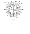
- the excitation voltage causes a voltage of same polarity S to be induced on the output coil (not shown) wound on stator magnetic poles 510 through 515 (referred to as the G1 output coil); another output coil (not shown) is wound on stator magnetic poles 516 through 521 (referred to as the G2 output coil) in order to induce a voltage having the same polarity N, different from the previous polarity S.
- an external magnetic flux ⁇ is introduced from the axial X0 direction to the stator 5 within the variable reluctance resolver.
- the axis Y0 is the axis perpendicular to the axis X0.
- a voltage of the same polarity S is induced on the G1 output coil by the excitation voltage, and each output coil is wound in such a way that the same polarity N, different from the previous polarity S, is induced on the G2 output coil.
- an external magnetic flux ⁇ is mixed in from the axial X0 direction
- the directions of the external magnetic flux ⁇ operating on the left and right sides of the axis Y0 are mutually opposing directions.
- an external magnetic flux ⁇ mixes in from the outer side of the stator 5
- an external magnetic flux ⁇ mixes in on the inside of the stator 5, which is to say the tip of each stator magnetic pole.
- the G2 output coil is wound in such a way as to have the opposite polarity to the G1 output coil polarity, but the voltage induced on the G1 and G2 output coils have the same polarity (N) and N, which are respectively added and output. In other words, all of the output wires are affected by external magnetic fluxes.
- variable reluctance resolver having an output coil with a number of fixed magnetic pole teeth different from Fig. 12, in which, as in Fig. 13, the axial multiple angle is 5 and the number of fixed magnetic poles is 20, is as shown below.
- an output coil (not shown) is wound in such a way that a same polarity S voltage is induced on the output coil (called the group A output coil) wound around a pair of 2 adjacent stator magnetic poles (for example stator magnetic poles 611 and 612) and a voltage of polarity N different from the group A output coil polarity S is induced on the output coil (called the group B output coil) wound around a group of 2 stator magnetic poles adjacent to group A.
- the group A output coil and group B output coil are alternately wound, with 2 adjacent stator magnetic poles forming one group.
- the external magnetic flux ⁇ directions on the left and right side of the axis Y0 are mutually opposing directions (on the left side of the axis Y0, the external magnetic flux ⁇ mixes in from the outside of the stator 5, and on the right side of the axis Y0, the external magnetic flux ⁇ mixes in from the inside of the stator 5, which is to say from the tip of each stator magnetic pole).
- the output coils are wound in such a way that the voltages induced in each output coil by the voltages applied to the excitation coil have the same polarity for each Group A output coil, and have the same polarity for each output coil in Group B within the applicable group, but for the induced voltage with respect to the external magnetic flux ⁇ , the direction of external magnetic flux with respect to the output coil is different between the left and right sides of the axis Y0.
- the polarity of the induced voltage in the output coil wound on the right side of the axis Y0 reverses and becomes the opposite polarity (shown respectively by the letters (S) and (N)).
- the induced voltages generated by the external magnetic flux ⁇ cancel one another out between the adjacent output coils on the same side as axis Y0, or between the output coils positioned to mutually face the axis X0 (for example, between the output coils 629 and 620 as indicated by the dotted line K).
- the case when the external magnetic flux ⁇ is introduced into the stator 5 from an angle and axis X0 direction (the horizontal direction between the stator magnetic poles 625, 626) that is different from the angle shown in Fig. 13 is shown in Fig. 14. That is, the induced voltage generated by the external magnetic flux ⁇ is not canceled between the adjacent output coils on the same side as axis Y0, or between the output coils positioned to mutually face the XO axis, whereas the voltage induced between the group A output coils (for example, between output coils 628 and 629) do mutually cancel one another.
- the external magnetic flux ⁇ and the stator magnetic pole angle differ in said mutually canceling output coils (for example, between output coils 628 and 629), and therefore the proportion of external magnetic flux ⁇ mixing differs. As a result, the induced voltage remains within each group without being canceled.
- the winding is such that the voltages produced by excitation voltages applied to excitation coils have respectively opposite N and S polarities in output coils 610, 621 and output coils 611, 620, but the directions of the external magnetic flux ⁇ which works on output coils 610, 621 and output coils 611, 620 are respectively reversed, since the external magnetic flux ⁇ direction is reversed.
- the output coils 610, 621 and 611, 620 have the opposite polarities N, S, but the voltages excited in both coils respectively each take on the same polarity N (N); each is respectively added together, and the output coils 610, 611, 620, 621 (the output coils outlined by reference numeral K1) directly receive the effect of the external magnetic flux.
- said magnetic shield requires a shield part with low magnetic resistance.
- Such shield materials are expensive, and shielding the variable reluctance resolver causes the device to increase in size.
- a magnetic shield is not provided, the effect of external magnetic flux will be received by all the output coils in output coils such as shown in Fig. 12, and, in output coils such as shown in Fig. 13, and problems will arise such as different output coils receiving the effect due to the direction in which the external magnetic flux mixes.
- An object of the present invention is to resolve problems in the prior art resolvers by providing a variable reluctance resolver equipped with an output coil with reduced susceptibility to the effects of external magnetic flux.
- Another object of the present invention is to provide a variable reluctance resolver that eliminates the effects of external magnet flux by having output coils wound such that the polarities of output voltages on the output coils wound around 3 or more stator magnetic poles are the same and all of the output coils are divided into an even number of groups.
- a variable reluctance resolver having multiple stator magnetic poles having resolver exciter coils and resolver output coils, which respectively output the X component and Y component of a rotary angle in accordance with the rotation of a rotor, wherein the resolver output coils are wound such that the output voltage polarities of output coils wound around at least 3 adjacent stator magnetic poles are the same, all the resolver output coils are divided into at least 2 or a greater even number of groups, and resolver output coils within each of the at least 2 or a greater even number of groups are connected in series such that output voltage polarities of adjacent groups differ with respect to one another.
- each group has outermost output coils and output coils between the outermost output coils and the number of turns of each of the outermost output coils is less than the number of turns of the output coils in between to thereby reduce the effect of external magnetic flux.
- variable reluctance resolver has an axis multiple angle of 7, an excitation pole pair count of 5, an output pole pair count of 2, and a stator magnetic pole count of 20, wherein all output coils are divided into 4 groups, one group includes output coils wound around 5 adjacent stator magnetic poles such that the polarity of output voltages in the group is the same, and the output coils in each of the four groups are serially connected so that the output voltage polarities of adjacent groups are different.
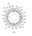
- Fig. 1 is a diagram depicting the polarity of output coils in the variable reluctance resolver of an embodiment of the present invention
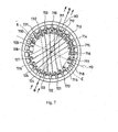
- Fig. 2 is a diagram depicting the effects of external magnetic flux on the variable reluctance resolver output coils in an embodiment of the present invention
- Fig. 3 is a diagram depicting the effect of external magnetic flux on the output coils when the angle at which external magnetic flux is introduced differs from the angle shown in Fig. 2;
- Fig. 4 is a diagram depicting the effect of external magnetic flux on the output coils when the angle at which external magnetic flux is introduced differs from the angle shown in Fig. 3;
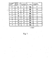
- Fig. 5 is a table showing the relationship between the axis multiple angle, the number of excitation pole pairs, the number of output pole pairs, and the number of slots in a variable reluctance resolver according to an embodiment of the present invention
- Fig. 6 is a diagram depicting the necessity for having two (2) or a greater even number of groups according to an embodiment of the present invention.
- Fig. 7 is a diagram depicting the effect of external magnetic flux on the output coils when the angle at which external magnetic flux is introduced differs from the angle shown in Fig. 6;
- Fig. 8A shows the stator magnetic pole numbers
- Fig. 8B shows the number of excitation coils wound around the stator magnetic poles shown in Fig. 8A;
- Fig. 8C shows the number of output coils wound around the stator magnetic poles
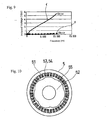
- Fig. 9 is a graph comparing the performance of the embodiment shown in Fig. 8 to a conventional variable reluctance resolver
- Fig. 10 is a diagram depicting a conventional variable reluctance resolver
- Fig. 11 is a diagram showing the conventional variable reluctance resolver in use
- Fig. 12 is a diagram showing the polarities of voltages produced in output coils wound around multiple stator magnetic poles formed on the stator of a conventional variable reluctance resolver;
- Fig. 13 is a diagram depicting the effect of external magnetic flux on output coils wound around stator magnetic poles different in number from that shown in Fig. 12, formed on a conventional variable reluctance resolver stator;
- Fig. 14 is a diagram depicting the effect of external magnetic flux on output coils when the angles of external magnetic flux introduction differ.
- variable reluctance resolver shown in Fig. 1 of a preferred embodiment in which the axial multiple angle is 7, the number of excitation pole pairs is 5, the number of output pole pairs is 2, and the number of stator magnetic poles is 20.
- the stator 5 in Fig. 1 has 20 stator magnetic poles 610 through 629 formed on the stator 5, but the configuration of the output coils wound around the stator magnetic poles differs as follows. First, explained is the polarity of the output coils.
- the stator magnetic poles 610 through 614, 615 through 619, 620 through 624, and 625 through 629 are respectively divided into 4 groups: Group 1 (G1), Group 2 (G2), Group 3 (G3), and Group 4 (G4).
- G1 Group 1
- G2 Group 2
- G3 Group 3
- G4 Group 4
- winding is done such that within G1, G2, G3, and G4 the polarity of the output voltages of each said output coil (not shown) will be the same due to the excitation voltage, and each is respectively serially connected.
- the output voltages of the output coils respectively serially connected within G1 and G3 will output a same polarity S voltage due to the excitation voltage.
- the output voltages of the output coils respectively serially connected within G2 and G4 will output a voltage of polarity N opposite to said G1 and G3 due to the excitation voltage.
- stator magnetic poles there are respectively 5 stator magnetic poles within each of the groups (G1, G2, G3, G4), and the number of turns of the output coils positioned on the outsides of each of the adjacent said groups is smaller than the number of turns of the output coils positioned to the inside of said outside stator magnetic poles.
- the number of turns of the output coils wound around the outside stator magnetic poles 610 and 614 positioned adjacent groups G4 and G2, respectively is fewer than the number of turns of the output coils wound on the stator magnetic poles 611 and 613 positioned to the inside of said stator magnetic poles 610 and 614.
- the number of turns of the output coils wound around the stator magnetic poles 611 and 613 adjacent G4 and G2 is smaller than the number of turns of the output coils wound around the stator magnetic pole 612 positioned to the inside of said stator magnetic poles 611 and 613.
- G2, G3, and G4 By thus making the number of turns of the output coil positioned on each adjacent said group smaller than the number of turns of the output coil positioned to the inside of said stator magnetic pole within the relevant group, the output voltage shown in Expression 10 due to the excitation voltage becomes smooth, and the accuracy of the variable reluctance resolver is improved.
- Fig. 2 explains the case in which external magnetic flux ⁇ from outside the variable reluctance resolver stator 5 is mixed into stator 5 from the axis X0 direction (the horizontal direction between stator magnetic poles 624, 625).
- Axis Y0 is perpendicular to axis X0.
- the output coils are wound in such a way that voltages induced in each output coil have the same polarity S for each G1 and G3 output coil, and have a polarity N (opposite to the polarity S of G1 and G3) for each of the output coils in G2 and G4, but there is a difference between the left and right sides with respect to the external magnetic flux ⁇ . That is to say, the polarity of the output coil wound on the right side of axis Y0 reverses and takes the opposite polarity (shown by the letters (S), (N) respectively). As a result, the voltages induced in the G1 and G3 output coils and the G2 and G4 output coils are mutually canceled between the output coils positioned so as to be mutually facing with respect to the center of the stator 5.
- FIG. 3 an example in which an external magnetic flux ⁇ is mixed into the stator 5 from a different direction to Fig. 2 (the horizontal direction between stator magnetic poles 625, 626) is shown. That is, using axis Y0 as a dividing line, the direction in which the external magnetic flux ⁇ works on the output coil to the left and right is the opposite direction. Therefore the voltage induced in the output coil by the external magnetic flux ⁇ reverses on the right side, taking axis Y0 as a dividing line (respectively shown by the legends (S), (N)).
- the voltages induced in the output coil cancel one another between the output coils positioned so as to mutually face one another centered on the stator 5 (for example, the output coils wound around the stator magnetic poles 629 and 619 shown by the letter K).
- the voltages induced between the output coils wound around the stator magnetic poles 614 and 624 also cancel one another out.
- the same is true for other output coils. In other words, even if an external magnetic flux ⁇ mixes in from a given angle, there is always an output coil in which the induced voltage is canceled.
- FIG. 4 an example in which an external magnetic flux ⁇ is mixed into the stator 5 from an angle or direction differing from Figs. 2 and 3 (the horizontal direction between stator magnetic poles 626, 627) is shown. That is, taking axis Y0 as a dividing line, the direction of the external magnetic flux ⁇ which works on the output coils on the left and right side thereof is the opposite direction.
- Fig. 5 explains the case in which, the output coils are wound around a row of 3 or more stator magnetic poles so that the output voltages have the same polarity, all the output coils are divided into 2 or more groups, and output coils are respectively serially connected so that the aforesaid adjacent group output voltages polarities mutually differ, with (O) showing the case where induced voltages are canceled, and (X) the case where they are not. In other words, it explains the necessity of division into 2 or a greater even number of groups.
- rows of four stator magnetic poles 710 through 713, 714 through 717, 718 through 721, 722 through 725, 726 through 729, and 730 through 733 are respectively divided into 6 groups, Group 1 (G1), Group 2 (G2), Group 3 (G3), Group 4 (G4), Group 5 (G5), and Group 6 (G6) so as to satisfy Expressions 1 and 2.
- each output coil not shown is wound such that in groups G1, G2, G3, G4, G5, and G6 the polarity of the output voltage in each output coil due to the excitation voltage applied to the excitation coil will be the same, and each is respectively serially connected.
- the output voltage of the output coils respectively serially connected in each of the aforementioned G1, G3, and G5 will output a same N polarity voltage.
- the output voltages of the output coils respectively serially connected in each of G2, G4, and G6 have the same polarity, and output an S polarity voltage opposite to the aforementioned G1, G3, and G5.
- Fig. 6 explains the case in which an external magnetic flux ⁇ is introduced from outside the variable reluctance resolver stator 5 to the stator 5 from the axis X0 direction (the horizontal direction between the stator magnetic poles 729, 730).
- Axis Y0 is perpendicular to axis X0.
- the winding is such that voltages of the same polarity N are induced in the G1, G3, and G5 output coils by the excitation voltage, and voltages of polarity S, different from the aforementioned N polarity, are induced in the G2, G4 and G6 output coils.
- an external magnetic flux ⁇ is introduced from outside the stator 5 to the left side of axis Y0, and an external magnetic flux ⁇ is introduced from the inside of the stator 5, which is to say the tip of each stator magnetic pole, to the right side of axis Y0.
- the voltage induced on each output coil differs between the left and right sides of the axis Y0 with respect to the external magnetic flux ⁇ .
- the polarity of the output coil wound around the right side of the axis inverts due to the external magnetic flux ⁇ and acts so as to generate an induced voltage of opposite polarity (shown respectively by (S) and (N)).
- the aforementioned induced voltages cancel one another between the output coils positioned so as to mutually oppose one another at left and right with respect to the axis Y0 (for example, the output coils wound around the stator magnetic poles 728 and 719 shown by letter K).
- variable reluctance resolver Embodiments of the variable reluctance resolver of the present invention are explained below.
- the stator magnetic pole number and specifications for the excitation coil and the output coil wound thereon are shown in Fig. 8.
- + or - indicates the polarity of the voltage produced by the coil.
- the multiple angle N, number of excitation pole pairs P, number of output pole pairs Q, and number of slots (output magnetic poles) S are respectively 7, 5, 2, and 20.
- Excitation coils are respectively wound around each stator magnetic pole 39 times so that the polarity of the output voltage on the excitation coil wound around the 2 unit (for example stator magnetic pole numbers 1 and 2) stator group of multiple adjacent stator magnetic poles is the same (-), and the output voltages from the group of excitation coils adjacent to the aforementioned group of excitation coils (stator magnetic pole numbers 3, 4 and 19, 20) have respectively different polarities (+) as shown in Fig. 8(b).
- the group adjacent to the said multiple stator magnetic pole is not limited to 2 in number; it need only be such that the number of excitation pole pairs P is 5.
- Fig. 8(c) the output coils are wound so that, as shown in Fig. 1, the polarities of the output voltage of the aforementioned output coils wound around a row of 5 stator magnetic poles are the same; taking the output coils for which the aforementioned output voltage polarities are the same as one group, all of the output coils are divided into 4 groups G1, G2, G3, and G4. Output coils in the same group are respectively serially connected so that the aforementioned adjacent group output voltage polarities mutually differ.
- G1 consists of stator magnetic pole numbers 1-5
- G2 consists of pole numbers 6-10
- G3 consists of pole number 11-15
- G4 consists of pole numbers 16-20.
- the number of turns of the output coils wound around the stator magnetic poles positioned on the side of each of the adjacent aforementioned groups is fewer than the number of turns of the output coils wound around the stator magnetic poles positioned on the inside of the aforementioned stator magnetic poles within the relevant group.
- the number of turns are 72, 189, 234, 189, and 72, respectively.
- Fig. 9 shows a comparison of characteristics between the conventional variable reluctance resolver shown in Fig. 12 and the embodiment of the present invention shown in Fig. 8.
- the induced voltage produced in the output coil by the external magnetic flux along the vertical axis and the change in frequency of the aforementioned external magnetic flux on the horizontal axis are respectively shown by the reference numbers i and ii.
- the induced voltage caused by external magnetic flux according to the variable reluctance resolver of the present invention is reduced to approximately 1/10th compared to a conventional variable reluctance resolver.
- a known magnetic shield may be applied to the variable reluctance resolver of the present invention, which of course would result in a further diminution of the effects of external magnetic fields.
- variable reluctance resolver of the present invention output coils wound in such a way that the voltages of output coils wound around a row of 3 or more stator magnetic poles have the same polarity are taken to be a single group. All the output coils are divided into an even number of groups, 2 or more, and output coils are respectively serially connected so that the aforementioned adjacent group output voltage polarities mutually differ.
Landscapes
- Physics & Mathematics (AREA)
- General Physics & Mathematics (AREA)
- Engineering & Computer Science (AREA)
- Power Engineering (AREA)
- Transmission And Conversion Of Sensor Element Output (AREA)
Abstract
Description
Claims (10)
- A variable reluctance resolver comprising multiple stator magnetic poles having resolver exciter coils and resolver output coils, which respectively output the X component and Y component or a rotary angle in accordance with the rotation of a rotor, wherein the resolver output coils are wound such that the output voltage polarities of resolver output coils wound around at least 3 adjacent stator magnetic poles are the same, the resolver output coils are divided into at least 2 or a greater even number of groups, and resolver output coils within each group of the at least two or a greater even number of groups are connected in series such that the output voltage polarities of adjacent groups of the at least 2 or a greater even number of groups differ with respect to one another.
- A variable reluctance resolver comprising a rotor, a stator body having a plurality of stator magnetic poles, resolver exciter coils would around the plurality of stator magnetic poles, and resolver output coils for outputting the X and Y components of a rotary angle of the rotor wound around the stator magnetic poles such that the plurality of resolver output coils are divided into an even number of at least tow groups, at least one group having resolver output coils would around at least three sequential stator magnetic poles, and each group of the even number of at least two groups connected in series to output the same polarity wherein adjacent groups of the even number of at least two groups have different voltage polarities.
- The variable reluctance resolver according to claim 1 or 2 wherein the variable reluctance resolver has an axis multiple angle of 7, an excitation pole pair count of 5, an output pole pair count of 2, and a stator magnetic pole count of 20, wherein all output coils are divided into 4 groups, one group of the 4 groups includes output coils would around 5 adjacent stator magnetic poles such that the polarity of output voltages in the group is the same, and the output coils in each of the four groups are serially connected so that the output voltage polarities of adjacent groups are different.
- A variable reluctance resolver comprising a rotor, a stator body having a plurality of stator magnetic poles, resolver exciter coils would around the plurality of stator magnetic poles, and resolver output coils outputting the X and Y components of a rotary angle of the rotor would around the stator magnetic poles and having a multiple angle of 7, an excitation pole pair count of at least 5, an output pole pair count wherein the excitation pole pair count and the output pole pair count add or subtract to equal the multiple angle of 7, and a stator magnetic pole count of 20, wherein all output coils are divided into 4 groups, one group of the 4 groups includes output coils would around 5 adjacent stator magnetic poles such that the polarity of output voltages in the group is the same, and the output coils in each of the four groups are serially connected so that the output voltage polarities of adjacent groups are different.
- The variable reluctance resolver according to any preceding claim wherein each group has outermost output coils and output coils between the outermost output coils and wherein the number of turns of each of the outermost output coils is less than the number of turns of the output coils between the outermost output coils to thereby reduce the effect of external magnetic flux.
- The variable reluctance resolver according to any of claims 1 to 4 wherein each group has two outermost output coils and three output coils between the outermost output coils and wherein the number of turns of each of the outermost output coils is less than the number of turns of the three output coils between the outermost output coils to thereby reduce the effect of external magnetic flux.
- The variable reluctance resolver according to claim 5 or 6 wherein the two outermost coils have the same number of turns.
- The variable reluctance resolver according to claim 6 wherein the three output coils between the outermost output coil include a middle coil between two adjacent output coils and wherein the middle coil has more turns than the two adjacent coils.
- The variable reluctance resolver according to any of claims 5 to 8 wherein the outermost coils of adjacent groups have the same number of turns.
- The variable reluctance resolver according to any preceding claim further comprising a magnetic shield to further reduce the effect of external magnetic flux.
Applications Claiming Priority (2)
| Application Number | Priority Date | Filing Date | Title |
|---|---|---|---|
| JP2002226302A JP4161172B2 (en) | 2002-08-02 | 2002-08-02 | Variable reluctance resolver |
| JP2002226302 | 2002-08-02 |
Publications (2)
| Publication Number | Publication Date |
|---|---|
| EP1387471A2 true EP1387471A2 (en) | 2004-02-04 |
| EP1387471A3 EP1387471A3 (en) | 2005-02-16 |
Family
ID=30112998
Family Applications (1)
| Application Number | Title | Priority Date | Filing Date |
|---|---|---|---|
| EP03254702A Ceased EP1387471A3 (en) | 2002-08-02 | 2003-07-28 | Variable reluctance resolver |
Country Status (3)
| Country | Link |
|---|---|
| US (1) | US7005771B2 (en) |
| EP (1) | EP1387471A3 (en) |
| JP (1) | JP4161172B2 (en) |
Families Citing this family (17)
| Publication number | Priority date | Publication date | Assignee | Title |
|---|---|---|---|---|
| JP4451248B2 (en) * | 2004-08-24 | 2010-04-14 | アイシン・エィ・ダブリュ株式会社 | Resolver |
| JP4781666B2 (en) * | 2004-11-17 | 2011-09-28 | 三菱電機株式会社 | Variable reluctance angle detector |
| JP4525628B2 (en) * | 2006-04-17 | 2010-08-18 | 三菱電機株式会社 | Rotation angle detector |
| JP4775294B2 (en) * | 2007-03-27 | 2011-09-21 | トヨタ自動車株式会社 | Resolver |
| JP4909430B2 (en) * | 2010-05-13 | 2012-04-04 | トヨタ自動車株式会社 | Variable reluctance resolver and method for producing the same |
| JP5764373B2 (en) * | 2011-04-15 | 2015-08-19 | 株式会社一宮電機 | Variable reluctance resolver |
| JP5174945B2 (en) * | 2011-09-02 | 2013-04-03 | 日本航空電子工業株式会社 | Variable reluctance resolver and rotation angle detector |
| JP6291946B2 (en) * | 2014-03-20 | 2018-03-14 | 株式会社ジェイテクト | Stator structure and resolver |
| US10620017B2 (en) | 2017-01-31 | 2020-04-14 | Rockwell Automation Technologies, Inc. | Curvilinear encoder system for position determination |
| US10480961B2 (en) | 2017-01-31 | 2019-11-19 | Rockwell Automation Technologies, Inc. | Hybrid encoder system for position determination |
| JP7478562B2 (en) * | 2020-03-27 | 2024-05-07 | ミネベアミツミ株式会社 | Resolver |
| FI130594B (en) * | 2020-05-27 | 2023-11-30 | Lappeenrannan Lahden Teknillinen Yliopisto Lut | A variable reluctance position sensor |
| US11601077B1 (en) | 2021-09-30 | 2023-03-07 | Rolls-Royce Corporation | Technologies for redundant shaft information feedback in electric machine systems including a resolver |
| US11646682B2 (en) | 2021-09-30 | 2023-05-09 | Rolls-Royce Corporation | Technologies for redundant shaft information feedback in multi-machine drive systems with multiple resolvers |
| US11646685B2 (en) | 2021-09-30 | 2023-05-09 | Rolls-Royce Corporation | Technologies for redundant shaft information feedback in electric machine systems having multiple resolvers |
| CN113794346B (en) * | 2021-10-09 | 2022-08-05 | 上海赢双电机有限公司 | Reluctance type self-angle-adjusting machine |
| WO2025126465A1 (en) * | 2023-12-15 | 2025-06-19 | 多摩川精機株式会社 | Resolver stator |
Family Cites Families (18)
| Publication number | Priority date | Publication date | Assignee | Title |
|---|---|---|---|---|
| GB769038A (en) * | 1953-12-01 | 1957-02-27 | Bendix Aviat Corp | Improvements in or relating to inductive devices |
| US3085192A (en) * | 1960-03-10 | 1963-04-09 | Tamar Electronics Ind Inc | Variable output transformer |
| US3041486A (en) * | 1960-04-15 | 1962-06-26 | United Aircraft Corp | Variable reluctance device |
| US4672347A (en) * | 1985-07-01 | 1987-06-09 | The Charles Stark Draper Laboratory, Inc. | Multi-speed resolver using ferrite stator and rotor structures |
| US4631510A (en) * | 1985-09-03 | 1986-12-23 | Powerton, Division Of Contraves Goerz Corporation | Harmonically graded airgap reluctance-type rotating electric resolver |
| US4733117A (en) * | 1987-04-27 | 1988-03-22 | The Superior Electric Company | Reluctance synchro/resolver |
| FR2679026B1 (en) * | 1991-07-11 | 1993-09-24 | Alsthom Gec | DEVICE FOR MEASURING THE ANGULAR POSITION OF A ROTOR IN RELATION TO A STATOR. |
| JP3047565B2 (en) * | 1991-10-29 | 2000-05-29 | 日本精工株式会社 | Variable reluctance resolver |
| DE4227439C2 (en) * | 1992-08-19 | 1994-06-01 | Litton Precision Prod Int | Magnetic shield resolver |
| JP2698013B2 (en) * | 1993-01-19 | 1998-01-19 | 彰 石崎 | Position detection device |
| JP3182493B2 (en) * | 1994-12-27 | 2001-07-03 | 多摩川精機株式会社 | Variable reluctance angle detector |
| JPH10239010A (en) * | 1997-02-26 | 1998-09-11 | Denso Corp | Variable reluctance resolver |
| JPH10288537A (en) * | 1997-04-15 | 1998-10-27 | Denso Corp | Variable reluctance resolver |
| US5949359A (en) * | 1997-05-09 | 1999-09-07 | Kollmorgen Corporation | Variable reluctance resolver to digital converter |
| US6137204A (en) * | 1998-05-22 | 2000-10-24 | Nsk Ltd. | VR-type resolver |
| US6472841B1 (en) * | 1998-09-03 | 2002-10-29 | Aspen Motion Technologies, Inc. | Low cost redundant resolver system |
| JP2001191931A (en) * | 2000-01-06 | 2001-07-17 | Nsk Ltd | Electric power steering device |
| JP2002054949A (en) * | 2000-08-11 | 2002-02-20 | Minebea Co Ltd | Multiple-winding variable reluctance resolver and multiple-winding variable reluctance resolver circuit |
-
2002
- 2002-08-02 JP JP2002226302A patent/JP4161172B2/en not_active Expired - Fee Related
-
2003
- 2003-07-28 EP EP03254702A patent/EP1387471A3/en not_active Ceased
- 2003-07-31 US US10/631,924 patent/US7005771B2/en not_active Expired - Fee Related
Also Published As
| Publication number | Publication date |
|---|---|
| US20040070389A1 (en) | 2004-04-15 |
| US7005771B2 (en) | 2006-02-28 |
| JP4161172B2 (en) | 2008-10-08 |
| EP1387471A3 (en) | 2005-02-16 |
| JP2004069374A (en) | 2004-03-04 |
Similar Documents
| Publication | Publication Date | Title |
|---|---|---|
| US7005771B2 (en) | Variable reluctance resolver | |
| EP0009102B1 (en) | A multipolar resolver | |
| EP2430402B1 (en) | Magnetoelectronic angle sensor, in particular a reluctance resolver | |
| US4481440A (en) | Permanent magnet brushless d-c motor with isolated sensor winding means | |
| US3281655A (en) | Inductive multi-speed resolver | |
| JP7583774B2 (en) | Multi-rotation angle detection device | |
| CN114977712B (en) | Variable reluctance resolver | |
| JP7642183B1 (en) | Multi-rotation angle detection device | |
| JP2023051163A (en) | rotation detector | |
| JP7572471B2 (en) | Multi-rotation angle detection device and segment counter therefor | |
| JP4336070B2 (en) | Rotary position detector | |
| WO2024090210A1 (en) | Multi-rotation angle detection device and segment counter for same | |
| JP6730732B2 (en) | Variable reluctance resolver | |
| CN117219425A (en) | Discrete reluctance rotary transformer | |
| JP2012005327A (en) | Resolver | |
| JP2001161054A (en) | Permanent magnet type stepping motor | |
| JPH037765Y2 (en) | ||
| JP2019124514A (en) | Multipolar resolver | |
| JP3410519B2 (en) | Three-phase claw-pole type permanent magnet type rotating electric machine | |
| CN113824234B (en) | Winding for reluctance type synchro and winding method thereof | |
| JPS61122504A (en) | Detecting device for rotating position | |
| JP5135277B2 (en) | Rotary position detector | |
| JP3030651B2 (en) | Linear position detector | |
| JPS6312914A (en) | Rotary position detector | |
| CN115598370A (en) | Variable magnetic flux type rotating speed sensor |
Legal Events
| Date | Code | Title | Description |
|---|---|---|---|
| PUAI | Public reference made under article 153(3) epc to a published international application that has entered the european phase |
Free format text: ORIGINAL CODE: 0009012 |
|
| AK | Designated contracting states |
Kind code of ref document: A2 Designated state(s): AT BE BG CH CY CZ DE DK EE ES FI FR GB GR HU IE IT LI LU MC NL PT RO SE SI SK TR |
|
| AX | Request for extension of the european patent |
Extension state: AL LT LV MK |
|
| PUAL | Search report despatched |
Free format text: ORIGINAL CODE: 0009013 |
|
| AK | Designated contracting states |
Kind code of ref document: A3 Designated state(s): AT BE BG CH CY CZ DE DK EE ES FI FR GB GR HU IE IT LI LU MC NL PT RO SE SI SK TR |
|
| AX | Request for extension of the european patent |
Extension state: AL LT LV MK |
|
| RIC1 | Information provided on ipc code assigned before grant |
Ipc: 7H 02K 3/28 B Ipc: 7H 02K 24/00 B Ipc: 7H 02K 19/12 B Ipc: 7H 02K 19/06 A |
|
| 17P | Request for examination filed |
Effective date: 20050808 |
|
| AKX | Designation fees paid |
Designated state(s): AT BE BG CH CY CZ DE DK EE ES FI FR GB GR HU IE IT LI LU MC NL PT RO SE SI SK TR |
|
| STAA | Information on the status of an ep patent application or granted ep patent |
Free format text: STATUS: THE APPLICATION HAS BEEN REFUSED |
|
| 18R | Application refused |
Effective date: 20080929 |