EP1387425A1 - Improved fluid passages for power generation equipment - Google Patents
Improved fluid passages for power generation equipment Download PDFInfo
- Publication number
- EP1387425A1 EP1387425A1 EP03254726A EP03254726A EP1387425A1 EP 1387425 A1 EP1387425 A1 EP 1387425A1 EP 03254726 A EP03254726 A EP 03254726A EP 03254726 A EP03254726 A EP 03254726A EP 1387425 A1 EP1387425 A1 EP 1387425A1
- Authority
- EP
- European Patent Office
- Prior art keywords
- fluid
- disposed
- channel
- fuel cell
- ribs
- Prior art date
- Legal status (The legal status is an assumption and is not a legal conclusion. Google has not performed a legal analysis and makes no representation as to the accuracy of the status listed.)
- Withdrawn
Links
Images

Classifications
-
- H—ELECTRICITY
- H01—ELECTRIC ELEMENTS
- H01M—PROCESSES OR MEANS, e.g. BATTERIES, FOR THE DIRECT CONVERSION OF CHEMICAL ENERGY INTO ELECTRICAL ENERGY
- H01M8/00—Fuel cells; Manufacture thereof
- H01M8/04—Auxiliary arrangements, e.g. for control of pressure or for circulation of fluids
-
- H—ELECTRICITY
- H01—ELECTRIC ELEMENTS
- H01M—PROCESSES OR MEANS, e.g. BATTERIES, FOR THE DIRECT CONVERSION OF CHEMICAL ENERGY INTO ELECTRICAL ENERGY
- H01M8/00—Fuel cells; Manufacture thereof
- H01M8/04—Auxiliary arrangements, e.g. for control of pressure or for circulation of fluids
- H01M8/04007—Auxiliary arrangements, e.g. for control of pressure or for circulation of fluids related to heat exchange
- H01M8/04067—Heat exchange or temperature measuring elements, thermal insulation, e.g. heat pipes, heat pumps, fins
- H01M8/04074—Heat exchange unit structures specially adapted for fuel cell
-
- H—ELECTRICITY
- H01—ELECTRIC ELEMENTS
- H01M—PROCESSES OR MEANS, e.g. BATTERIES, FOR THE DIRECT CONVERSION OF CHEMICAL ENERGY INTO ELECTRICAL ENERGY
- H01M8/00—Fuel cells; Manufacture thereof
- H01M8/02—Details
-
- H—ELECTRICITY
- H01—ELECTRIC ELEMENTS
- H01M—PROCESSES OR MEANS, e.g. BATTERIES, FOR THE DIRECT CONVERSION OF CHEMICAL ENERGY INTO ELECTRICAL ENERGY
- H01M8/00—Fuel cells; Manufacture thereof
- H01M8/02—Details
- H01M8/0202—Collectors; Separators, e.g. bipolar separators; Interconnectors
- H01M8/0269—Separators, collectors or interconnectors including a printed circuit board
-
- H—ELECTRICITY
- H01—ELECTRIC ELEMENTS
- H01M—PROCESSES OR MEANS, e.g. BATTERIES, FOR THE DIRECT CONVERSION OF CHEMICAL ENERGY INTO ELECTRICAL ENERGY
- H01M8/00—Fuel cells; Manufacture thereof
- H01M8/04—Auxiliary arrangements, e.g. for control of pressure or for circulation of fluids
- H01M8/04007—Auxiliary arrangements, e.g. for control of pressure or for circulation of fluids related to heat exchange
-
- Y—GENERAL TAGGING OF NEW TECHNOLOGICAL DEVELOPMENTS; GENERAL TAGGING OF CROSS-SECTIONAL TECHNOLOGIES SPANNING OVER SEVERAL SECTIONS OF THE IPC; TECHNICAL SUBJECTS COVERED BY FORMER USPC CROSS-REFERENCE ART COLLECTIONS [XRACs] AND DIGESTS
- Y02—TECHNOLOGIES OR APPLICATIONS FOR MITIGATION OR ADAPTATION AGAINST CLIMATE CHANGE
- Y02E—REDUCTION OF GREENHOUSE GAS [GHG] EMISSIONS, RELATED TO ENERGY GENERATION, TRANSMISSION OR DISTRIBUTION
- Y02E60/00—Enabling technologies; Technologies with a potential or indirect contribution to GHG emissions mitigation
- Y02E60/30—Hydrogen technology
- Y02E60/50—Fuel cells
Definitions
- the present invention relates generally to power generation equipment, and more particularly to improved fluid passages for solid oxide fuel cells.
- a high temperature, solid oxide fuel cell stack is typically comprises planar cross flow fuel cells, counterflow fuel cells and parallel flow fuel cells that are constructed from flat single cell members and associated with fuel and air distribution equipment.
- Such members typically comprise trilayer anode/electrolyte/cathode components which conduct current from cell to cell and comprise at least one interconnect having channels for gas flow into a cubic structure or stack.
- Solid oxide fuel cells generate electrical energy through electrochemical reactions between an oxidant and hydrocarbon fuel gas to produce a flow of electrons in an external circuit.
- solid oxide fuel cells generate waste heat that is typically removed via an oxidant in order to maintain a desired temperature level of solid oxide fuel cell components such as the anode, cathode and electrolyte.
- Solid oxide fuel cells have demonstrated the potential for high efficiency and low pollution in power generation, some problems remain associated with temperature regulation of the components in solid oxide fuel cells.
- Solid oxide fuel cells typically comprise cooling channels in which the oxidant, typically air, is used to aid in the transfer or removal of the waste heat so as to maintain the stack temperature at or below prescribed limits and maintain a predetermined thermal gradient in the solid oxide fuel cell.
- cooling channels typically comprise smooth straight channels that have an undesired characteristic of providing low thermal transfer coefficients between the channel surface and the oxidant.
- One embodiment of the present invention comprises a cooling apparatus for fuel cell components comprising a base plate having a first end and a second end and a first side plate coupled to the first end and a second side plate coupled to the second end.
- a plurality of bottom ribs are coupled to the base plate and a plurality of upper ribs are coupled to the bottom ribs.
- a top channel and a bottom channel are formed between each of the plurality of upper ribs and each of the plurality of bottom ribs, respectively, wherein the top channel and the bottom channel are disposed to allow a flow of a fluid therethrough and disposed to allow a portion of the fluid to alternate between the top channel and the bottom channel at a flow redirection area so as to enhance the heat transfer rate between the fluid and the fuel cell components.
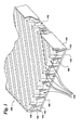
- a cooling apparatus 100 is provided for a fuel cell in Figure 1.
- the cooling apparatus 100 comprises a (meaning at least one) base plate 110 having a first end 112 and a second end 114.
- a first side plate 120 is coupled to the first end 112 and a second side plate 125 is coupled to the second end.
- the term “coupled” refers to a mechanical attachment of members of cooling apparatus 100 and includes, without limitation, welding, brazing, soldering and the like, as well as machining and casting the members as a single part.
- a plurality of bottom ribs 160 coupled to the base plate 110 and a plurality of upper ribs 150 coupled to the bottom ribs 160.
- cooling apparatus comprises a (meaning at least one) top channel 130 and a (meaning at least one) bottom channel 140 formed between each of said plurality of upper ribs 150 and each of said plurality of bottom ribs 160, respectively.
- the top channel 130 and the bottom channel 140 are disposed to allow a flow of a fluid 210 therethrough.
- the top channel 130 and the bottom channel 140 are disposed to allow a portion of the fluid 210 to alternate between the top channel 130 and the bottom channel 130 at a flow redirection area 170 so as to enhance the heat transfer rate between the fluid 210 and the fuel cell components, for example, an anode 180, cathode 200 and electrolyte 190 (see Figure 2).
- the fuel cell is typically selected from the group consisting of solid oxide fuel cells, proton exchange membrane or solid polymer fuel cells, molten carbonate fuel cells, phosphoric acid fuel cells, alkaline fuel cells, direct methanol fuel cells, regenerative fuel cells, and protonic ceramic fuel cells.
- an oxidant e.g. oxygen molecules
- a cathode electrolyte interface 220 For purposes of simplicity, the term “solid oxide fuel cell” will hereinafter be generically described as a "fuel cell”.
- the oxygen ions migrate through the electrolyte 190 to combine with a fuel (typically gaseous fuel) at an anode electrolyte interface 230 thereby releasing electrons at the anode 180.
- the electrons are collected at the cathode 200 through an external load circuit (not shown) thereby generating a flow of electrical current in the external load circuit from the anode 180 to the cathode 200.
- the fuel cell As a result of the interactions at the anode electrolyte interface 230, the fuel cell generates heat that must be removed in order to maintain a desired temperature level and a predetermined thermal gradient in the fuel cell.
- such removal of heat is typically accomplished by disposing upper ribs 150 of cooling apparatus 100 over the cathode 200 and introducing the fluid 210, typically an oxidant, into the top and bottom channels 130,140 (as indicated by the solid arrows in drawing Figure 2) so that the oxidant fluid flow removes heat energy from the fuel cell as it travels therethrough.
- the terms “over”, “thereon”, “therein”, “above”, “under”, “into”, “on” and the like are used to refer to relative location of elements of the cooling apparatus 100 as illustrated in the Figures and are not meant to be a limitation in any manner with respect to the orientation or operation of the cooling apparatus 100.
- the upper ribs 150 are typically disposed at an angle (designated “A” in drawing Figure 2) in the range between about 30 degrees and about 120 degrees with respect to the bottom ribs 160.
- the removal of heat is accomplished by disposing the upper ribs 150 of cooling apparatus 100 over the anode 180 (not shown) and introducing the fluid 210, typically a gaseous fuel, into the top and bottom channels 130,140. It will be appreciated that the function of the cooling apparatus 100 and any embodiments mentioned herein are also applicable to such gaseous fuel.
- the cooling apparatus 100 comprises the top channel 130 and the bottom channel 140 being disposed to allow a portion of the fluid 210 to alternate between the top channel 130 and the bottom channel 140 at a flow redirection area 170 so as to enhance the heat transfer rate between the fluid 210 and the fuel cell components, for example, the anode 180, cathode 200 and electrolyte 190.
- the fluid 210 is introduced into the top and bottom channels 130, 140 wherein a top channel fluid 240 (a portion of fluid 210 introduced at the top channel 130) is redirected at the flow redirection area 170 to the bottom channel 140 and a bottom channel fluid 250 (a portion of fluid 210 introduced at the bottom channel 140) is redirected at the flow redirection area 170 to the top channel 130.
- flow redirection area refers to an area where a portion of the fluid 210 (e.g. the top channel fluid 240) changes direction and enters the bottom channel 140 and it also refers to an area where a portion of the fluid 210 (the bottom channel fluid 250) changes direction and enters the top channel 130.
- FIG. 2 shows the top channel fluid 240 introduced through the top channel 130 until reaching the flow redirection area 170.
- the flow redirection area 170 serves to locally enhance the heat transfer from on all sides of the top and bottom channels 130,140 compared to conventional fuel cells having smooth straight channels.
- Such localized heat transfer enhancement created is typically carried downstream by the top channel fluid 240 and is subsequently redirected to the bottom channel 140 at the flow redirection area 170 when the top channel fluid 240 contacts one of the first or second side plates 120,125.
- One aspect of the present invention is that by redirecting the flow of fluid 210 to either the top channel 130 or the bottom channel 140, the variance of the thermal gradient present in the fuel cell is reduced compared to conventional fuel cells.
- Such thermal gradients typically result from varying fuel utilization, variable fuel cell component material properties or variable anode or cathode porosities, for example.
- the number of top and bottom channels 130,140 and the number of flow redirection areas 170 are left to the artisan to determine based upon predetermined design requirements, for example, heat transfer rate and thermal gradient uniformity.
- the width and length of the region between the side walls 120 and 125 as well as the shape and dimensions for the top and bottom channels 130,140 and the upper and bottom ribs 150,160 are left to the artisan depending upon a desired application.
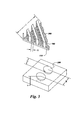
- Figures 1 and 3 show a plurality of concavities 260 disposed on a surface portion of the top channel 130 and disposed on a surface portion of the bottom channel 140.
- the term "concavity” refers to depressions, indentations, dimples, pits or the like.
- the plurality of concavities 260 are disposed on a surface portion of the upper ribs 150 and the bottom ribs 160.
- the shape of the concavities 140 is typically hemispherical or inverted and truncated conically shaped. In some embodiments, the shape of the concavities 140 is typically any sector of a full hemisphere. It will be appreciated that in other embodiments, the concavities 140 may be disposed on an entirety or a surface portion of the cathode 200, the anode 180 or both the cathode 200 and anode 180 depending on a desired application.
- the concavities 260 are formed on the abovementioned surfaces in a predetermined pattern that serves to enhance the heat transfer from the fuel cell components, typically the anode 180, cathode 200 and electrolyte 190, to the fluid 210, such as the oxidant (see Figure 2).
- the concavities 260 are disposed on an entirety of the abovementioned surfaces. In another embodiment, the concavities 260 are disposed on a portion of the abovementioned surfaces.
- the fluid 210 is introduced into the top and bottom channels 130, 140 of cooling apparatus 100 and is disposed over the concavities 260 (see Figure 1).
- hydrodynamic interactions between the fluid 210 and the concavities 260 cause the heat transfer rate in the fuel cell to increase compared to conventional fuel cells.
- hydrodynamic interactions refers to the interactions between the concavities 260 and the fluid 210 in which each concavity 260 creates a pressure field within the concavity 260 so as to create a vortex pattern (not shown) in a portion of the flow of the fluid 210.
- the heat transfer rate between the fluid 210 and each respective concavity 260 is typically increased (compared to designs having surfaces without concavities) due to an increase in the surface area caused by the shape of each respective concavity 260.
- the fluid 210 interacts with such increased surface area thereby enhancing the removal of heat energy from the fuel cell.
- the increase in heat transfer rate is not directly proportional to the increase in the surface area and may often be greater depending upon a predetermined design.
- the depth "Y” for a given one of the concavities 260 typically remains constant through the length "L" of the cooling apparatus 100 (see Figure 3).
- the depth “Y” is generally in the range between about 0.10 to about 0.50 times the concavity surface diameter "D".
- the depth "Y” of the concavities 260 is in the range between about 0.002 inches to about 0.25 inches.
- the center-to-center spacing "X" of the concavities 260 is generally in the range between about 1.1 to about 2 times the surface diameter "D" of the concavities 260.
- the concavities 260 are typically formed by using a pulse electrochemical machining (PECM) process.
- the concavities 260 are typically formed by using an electro-discharge machining (EDM) process.
Landscapes
- Life Sciences & Earth Sciences (AREA)
- Engineering & Computer Science (AREA)
- Manufacturing & Machinery (AREA)
- Sustainable Development (AREA)
- Sustainable Energy (AREA)
- Chemical & Material Sciences (AREA)
- Chemical Kinetics & Catalysis (AREA)
- Electrochemistry (AREA)
- General Chemical & Material Sciences (AREA)
- Fuel Cell (AREA)
Applications Claiming Priority (2)
| Application Number | Priority Date | Filing Date | Title |
|---|---|---|---|
| US10/064,605 US7011904B2 (en) | 2002-07-30 | 2002-07-30 | Fluid passages for power generation equipment |
| US64605 | 2002-07-30 |
Publications (1)
| Publication Number | Publication Date |
|---|---|
| EP1387425A1 true EP1387425A1 (en) | 2004-02-04 |
Family
ID=30113654
Family Applications (1)
| Application Number | Title | Priority Date | Filing Date |
|---|---|---|---|
| EP03254726A Withdrawn EP1387425A1 (en) | 2002-07-30 | 2003-07-29 | Improved fluid passages for power generation equipment |
Country Status (7)
| Country | Link |
|---|---|
| US (1) | US7011904B2 (un) |
| EP (1) | EP1387425A1 (un) |
| JP (1) | JP2004063472A (un) |
| KR (1) | KR20040011376A (un) |
| CN (1) | CN1477726A (un) |
| AU (1) | AU2003227334A1 (un) |
| CA (1) | CA2435534A1 (un) |
Cited By (2)
| Publication number | Priority date | Publication date | Assignee | Title |
|---|---|---|---|---|
| FR2913819A1 (fr) * | 2007-03-16 | 2008-09-19 | Air Liquide | Plaque de pile a combustible, empilage de cellules de pile a combustible et pile a combustible correspondante |
| FR2932925A1 (fr) * | 2008-06-20 | 2009-12-25 | Air Liquide | Plaque de pile a combustible, empilage de cellules de pile a combustible et pile a combustible comprenant un empilage. |
Families Citing this family (10)
| Publication number | Priority date | Publication date | Assignee | Title |
|---|---|---|---|---|
| KR100594185B1 (ko) * | 2004-12-02 | 2006-06-28 | 주식회사 이노윌 | 3차원 마이크로 채널을 구비한 플레이트 및 이를 이용한열교환기 |
| US7150929B2 (en) * | 2004-12-29 | 2006-12-19 | Utc Fuel Cells, Llc | Fuel cell coolers with inverse flow and condensation zone |
| JP4892870B2 (ja) * | 2005-05-26 | 2012-03-07 | トヨタ自動車株式会社 | 燃料電池用セパレータ |
| CN100449833C (zh) * | 2005-08-26 | 2009-01-07 | 比亚迪股份有限公司 | 一种燃料电池的流场板 |
| US7740988B2 (en) * | 2006-03-31 | 2010-06-22 | Fuelcell Energy, Inc. | Fuel cell plate structure having baffles in wet seal area |
| US7838168B2 (en) * | 2006-08-24 | 2010-11-23 | Salter L Carlton | Functionally integrated hydrogen fuel cell |
| US7722327B1 (en) | 2007-04-03 | 2010-05-25 | Florida Turbine Technologies, Inc. | Multiple vortex cooling circuit for a thin airfoil |
| US8117969B1 (en) * | 2008-08-05 | 2012-02-21 | Bnsf Railway Company | Hydrogen fuel cell hybrid locomotives |
| US8522691B1 (en) * | 2012-09-28 | 2013-09-03 | Electro-Motive Diesel, Inc. | Apparatus and method for supplemental cooling |
| ES2718727T3 (es) * | 2014-06-27 | 2019-07-04 | Nuvera Fuel Cells Llc | Campos de flujo para su uso con una celda electroquímica |
Citations (7)
| Publication number | Priority date | Publication date | Assignee | Title |
|---|---|---|---|---|
| US4732713A (en) * | 1984-10-03 | 1988-03-22 | Aktiebolaget Carl Munters | Insertable contact body |
| US4781248A (en) * | 1986-07-03 | 1988-11-01 | W. Schmidt Gmbh & Co., K.G. | Plate heat exchanger |
| JPH07105960A (ja) * | 1993-10-07 | 1995-04-21 | Sanyo Electric Co Ltd | 燃料電池 |
| US5806584A (en) * | 1993-12-29 | 1998-09-15 | Commissariat A L'energie Atomique | Heat exchanger with improved plates |
| WO1999057781A1 (en) * | 1998-05-02 | 1999-11-11 | Ballard Power Systems Inc. | Fuel cell stack assembly |
| DE19933426A1 (de) * | 1999-07-16 | 2001-01-25 | Clyde Bergemann Ega Gmbh | Wärmetauschermodul |
| US6199626B1 (en) * | 1999-02-05 | 2001-03-13 | Long Manufacturing Ltd. | Self-enclosing heat exchangers |
Family Cites Families (6)
| Publication number | Priority date | Publication date | Assignee | Title |
|---|---|---|---|---|
| US4155981A (en) * | 1978-02-09 | 1979-05-22 | The United States Of America As Represented By The Secretary Of The Navy | Rectangular cell honeycomb chemical converter-heat exchanger |
| US5660525A (en) | 1992-10-29 | 1997-08-26 | General Electric Company | Film cooled slotted wall |
| SE512384C2 (sv) | 1998-05-25 | 2000-03-06 | Abb Ab | Komponent för en gasturbin |
| DE19923426B4 (de) | 1999-05-21 | 2005-07-14 | Aristoteles Heinz | Getriebe |
| US6472095B2 (en) * | 2000-12-29 | 2002-10-29 | Utc Fuel Cells, Llc | Hybrid fuel cell reactant flow fields |
| US6917932B2 (en) * | 2002-05-01 | 2005-07-12 | International Business Machines Corporation | Dynamic optimization of multi-feature queries |
-
2002
- 2002-07-30 US US10/064,605 patent/US7011904B2/en not_active Expired - Lifetime
-
2003
- 2003-07-17 CA CA002435534A patent/CA2435534A1/en not_active Abandoned
- 2003-07-29 JP JP2003281407A patent/JP2004063472A/ja active Pending
- 2003-07-29 EP EP03254726A patent/EP1387425A1/en not_active Withdrawn
- 2003-07-29 KR KR1020030052196A patent/KR20040011376A/ko not_active Application Discontinuation
- 2003-07-30 CN CNA031436986A patent/CN1477726A/zh active Pending
- 2003-07-30 AU AU2003227334A patent/AU2003227334A1/en not_active Abandoned
Patent Citations (8)
| Publication number | Priority date | Publication date | Assignee | Title |
|---|---|---|---|---|
| US4732713A (en) * | 1984-10-03 | 1988-03-22 | Aktiebolaget Carl Munters | Insertable contact body |
| US4781248A (en) * | 1986-07-03 | 1988-11-01 | W. Schmidt Gmbh & Co., K.G. | Plate heat exchanger |
| JPH07105960A (ja) * | 1993-10-07 | 1995-04-21 | Sanyo Electric Co Ltd | 燃料電池 |
| US5806584A (en) * | 1993-12-29 | 1998-09-15 | Commissariat A L'energie Atomique | Heat exchanger with improved plates |
| WO1999057781A1 (en) * | 1998-05-02 | 1999-11-11 | Ballard Power Systems Inc. | Fuel cell stack assembly |
| US6199626B1 (en) * | 1999-02-05 | 2001-03-13 | Long Manufacturing Ltd. | Self-enclosing heat exchangers |
| US20020026999A1 (en) * | 1999-02-05 | 2002-03-07 | Wu Alan K. | Self-enclosing heat exchanger with crimped turbulizer |
| DE19933426A1 (de) * | 1999-07-16 | 2001-01-25 | Clyde Bergemann Ega Gmbh | Wärmetauschermodul |
Non-Patent Citations (1)
| Title |
|---|
| PATENT ABSTRACTS OF JAPAN vol. 1995, no. 07 31 August 1995 (1995-08-31) * |
Cited By (2)
| Publication number | Priority date | Publication date | Assignee | Title |
|---|---|---|---|---|
| FR2913819A1 (fr) * | 2007-03-16 | 2008-09-19 | Air Liquide | Plaque de pile a combustible, empilage de cellules de pile a combustible et pile a combustible correspondante |
| FR2932925A1 (fr) * | 2008-06-20 | 2009-12-25 | Air Liquide | Plaque de pile a combustible, empilage de cellules de pile a combustible et pile a combustible comprenant un empilage. |
Also Published As
| Publication number | Publication date |
|---|---|
| US20040023093A1 (en) | 2004-02-05 |
| AU2003227334A1 (en) | 2004-02-19 |
| KR20040011376A (ko) | 2004-02-05 |
| CN1477726A (zh) | 2004-02-25 |
| JP2004063472A (ja) | 2004-02-26 |
| CA2435534A1 (en) | 2004-01-30 |
| US7011904B2 (en) | 2006-03-14 |
Similar Documents
| Publication | Publication Date | Title |
|---|---|---|
| US7867666B2 (en) | Fuel cell with triangular buffers for reactant gas and coolant | |
| JP4753599B2 (ja) | 燃料電池 | |
| KR20010089507A (ko) | 중합체 전해질 막 연료 전지용 시트 금속 이극판 디자인 | |
| KR102109057B1 (ko) | 고체 산화물 연료 전지 또는 고체 산화물 전해 전지 및 이러한 전지를 작동시키기 위한 방법 | |
| US7011904B2 (en) | Fluid passages for power generation equipment | |
| US20100167105A1 (en) | Bipolar plate for fuel cells | |
| CN115064722B (zh) | 一种空冷型质子交换膜燃料电池的散热金属冲压双极板 | |
| KR101008212B1 (ko) | 고체산화물 연료전지 | |
| EP1852931A1 (en) | Separator for Fuel Cell | |
| EP1391955A2 (en) | Fluid passages for power generation equipment | |
| US11811104B2 (en) | Bipolar plate with undulating channels | |
| CN210535761U (zh) | 一种燃料电池金属极板 | |
| US7022429B2 (en) | Fluid passages for power generation equipment | |
| JP7077933B2 (ja) | 燃料電池セル | |
| KR102025750B1 (ko) | 연료전지 분리판 및 이를 포함하는 연료전지 스택 | |
| KR20200000913A (ko) | 연료전지용 세퍼레이터 | |
| CN212517258U (zh) | 风冷燃料电池单元 | |
| EP4075554B1 (en) | Fuel cell with a separator and fuel cell stack | |
| KR102701412B1 (ko) | 언듈레이팅 채널들이 구비된 바이폴라 플레이트 | |
| JP2001202974A (ja) | 固体高分子型燃料電池スタック | |
| CN116544435A (zh) | 固体氧化物燃料电池的连接体及其制备方法、应用和电堆 | |
| KR20090073584A (ko) | 연료전지용 세퍼레이터 및 이를 포함하는 연료전지 | |
| JP2010170947A (ja) | 燃料電池スタック |
Legal Events
| Date | Code | Title | Description |
|---|---|---|---|
| PUAI | Public reference made under article 153(3) epc to a published international application that has entered the european phase |
Free format text: ORIGINAL CODE: 0009012 |
|
| AK | Designated contracting states |
Kind code of ref document: A1 Designated state(s): AT BE BG CH CY CZ DE DK EE ES FI FR GB GR HU IE IT LI LU MC NL PT RO SE SI SK TR |
|
| AX | Request for extension of the european patent |
Extension state: AL LT LV MK |
|
| 17P | Request for examination filed |
Effective date: 20040804 |
|
| AKX | Designation fees paid |
Designated state(s): AT BE BG CH CY CZ DE DK EE ES FI FR GB GR HU IE IT LI LU MC NL PT RO SE SI SK TR |
|
| 17Q | First examination report despatched |
Effective date: 20040927 |
|
| STAA | Information on the status of an ep patent application or granted ep patent |
Free format text: STATUS: THE APPLICATION IS DEEMED TO BE WITHDRAWN |
|
| 18D | Application deemed to be withdrawn |
Effective date: 20080201 |