EP1387376A1 - Switch lock-off mechanism for power tools - Google Patents
Switch lock-off mechanism for power tools Download PDFInfo
- Publication number
- EP1387376A1 EP1387376A1 EP20030016204 EP03016204A EP1387376A1 EP 1387376 A1 EP1387376 A1 EP 1387376A1 EP 20030016204 EP20030016204 EP 20030016204 EP 03016204 A EP03016204 A EP 03016204A EP 1387376 A1 EP1387376 A1 EP 1387376A1
- Authority
- EP
- European Patent Office
- Prior art keywords
- power tool
- lock
- housing
- power
- power switch
- Prior art date
- Legal status (The legal status is an assumption and is not a legal conclusion. Google has not performed a legal analysis and makes no representation as to the accuracy of the status listed.)
- Granted
Links
Images
Classifications
-
- H—ELECTRICITY
- H01—ELECTRIC ELEMENTS
- H01H—ELECTRIC SWITCHES; RELAYS; SELECTORS; EMERGENCY PROTECTIVE DEVICES
- H01H21/00—Switches operated by an operating part in the form of a pivotable member acted upon directly by a solid body, e.g. by a hand
- H01H21/02—Details
- H01H21/04—Cases; Covers
- H01H21/10—Casing of switch constituted by a handle serving a purpose other than the actuation of the switch
-
- H—ELECTRICITY
- H01—ELECTRIC ELEMENTS
- H01H—ELECTRIC SWITCHES; RELAYS; SELECTORS; EMERGENCY PROTECTIVE DEVICES
- H01H3/00—Mechanisms for operating contacts
- H01H3/02—Operating parts, i.e. for operating driving mechanism by a mechanical force external to the switch
- H01H3/20—Operating parts, i.e. for operating driving mechanism by a mechanical force external to the switch wherein an auxiliary movement thereof, or of an attachment thereto, is necessary before the main movement is possible or effective, e.g. for unlatching, for coupling
-
- Y—GENERAL TAGGING OF NEW TECHNOLOGICAL DEVELOPMENTS; GENERAL TAGGING OF CROSS-SECTIONAL TECHNOLOGIES SPANNING OVER SEVERAL SECTIONS OF THE IPC; TECHNICAL SUBJECTS COVERED BY FORMER USPC CROSS-REFERENCE ART COLLECTIONS [XRACs] AND DIGESTS
- Y10—TECHNICAL SUBJECTS COVERED BY FORMER USPC
- Y10S—TECHNICAL SUBJECTS COVERED BY FORMER USPC CROSS-REFERENCE ART COLLECTIONS [XRACs] AND DIGESTS
- Y10S83/00—Cutting
- Y10S83/01—Safety devices
-
- Y—GENERAL TAGGING OF NEW TECHNOLOGICAL DEVELOPMENTS; GENERAL TAGGING OF CROSS-SECTIONAL TECHNOLOGIES SPANNING OVER SEVERAL SECTIONS OF THE IPC; TECHNICAL SUBJECTS COVERED BY FORMER USPC CROSS-REFERENCE ART COLLECTIONS [XRACs] AND DIGESTS
- Y10—TECHNICAL SUBJECTS COVERED BY FORMER USPC
- Y10T—TECHNICAL SUBJECTS COVERED BY FORMER US CLASSIFICATION
- Y10T83/00—Cutting
- Y10T83/869—Means to drive or to guide tool
- Y10T83/8773—Bevel or miter cut
Definitions
- This invention relates generally to in general to power tools, and, in particular to a power tool with an ambidextrous lock-out mechanism for use with lockable power switches.
- Lock-out mechanisms for lockable power switches are known in the art. These mechanisms are intended to unlock the locked power switch or trigger of a motor driven tool or machine in order to allow the actuation of the motor by the power switch.
- the power switch of many power tools such as circular saws, table saws of various sorts, hedge trimmers and the like is provided with a lock mechanism in order to prevent unintended operation of a power tool or machine through inadvertent actuation of the power switch prior to operation of the power tool or machine.
- the user is required to actuate the lock-out mechanism in order to bring the lock mechanism of the power switch in an unlocked position in which the power switch can be depressed and, accordingly, the motor can be actuated.
- a motor is used to power a circular saw blade mounted on an cantilevered arm.
- a platform including guides is also provided.
- the blade has a housing which covers the unused area of the blade.
- a handle is attached to extend above or besides the blade for convenient operation of the saw, and on the handle is installed a power lever or switch which can be of the trigger-switch variety.
- the user may hold the item to be sawed with one hand, and subsequently raise and lower the saw blade with the other hand.
- the user first positions the wood on a platform located below the blade. The user then turns the machine power on by grasping the handle and squeezing or depressing the power lever switch. Without removing the hand from the handle, the user then lowers the saw blade down onto the trim while holding the work piece on the platform with the other hand in order to make the desired cuts.
- the user raises the handle and turns off the saw by releasing the power switch. After release the power switch moves back to its rest position in which the motor is inactuated.
- the power switch will be locked by lock means as soon as it comes into its rest position. If locked, the power switch cannot be moved into the actuation position in which the motor starts turning. To operate the tool or machine, the user has to actuate the lock-out means first in order to release the power switch.
- lock-out mechanisms are designed for the right-handed individual.
- the lock-out mechanism In an embodiment with a grip handle arranged in a substantially horizontal manner the lock-out mechanism is positioned left to the power switch. In this case the mechanisms involve intended movement of the right thumb in order to actuate the lock-out mechanism.
- Left-handed operators must either use both hands for unlocking and depressing the power switch, or they must inconveniently use their right hand for operation of the saw. Thus, left-handed operators are unable to realize the same ergonomic benefits from the lock-out mechanisms as do right-handed operators.
- US Patent No. 5,969,312 discloses an ambidextrous lock-out mechanism. However, such mechanism is difficult to use.
- an improved power tool is employed.
- the power tool includes a motor, a housing forming a handle, a power switch disposed within the handle operatively associated with the motor, the power switch being movable between "on” and “off” positions via a trigger which is pivotable about a first axis, a lock-out link pivotably attached to the housing, the lock-out link movable between a first position contacting the power switch for preventing movement of the power switch to the "on” position, and a second position not contacting the power switch, allowing movement of the power switch to the "on” position, the lock-out link pivoting between the first and second positions about a second axis non-parallel to the first axis, and a first button disposed on the housing for moving the lock-out link between the first and second positions.
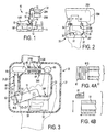
- a miter saw 10 typically has a base 11, which may include a rotatable table 12 rotatably attached to base 11.
- a pivot arm 14 is pivotally attached to a trunnion (not shown) to allow a chopping function.
- the trunnion in turn may be pivotally attached to the base 11 and/or table 12, to allow the trunnion and pivot arm 14 to pivot relative to the base 11.
- the pivot arm 14 carries a saw assembly which includes motor housing 20H, a motor 20M disposed in motor housing 20H, a blade 17 driven by motor 20M, an upper blade guard 15 covering an upper part of the blade 17, and a lower blade guard 16 pivotally attached to upper blade guard 15 for covering a lower part of the blade 17.
- a fence assembly 19 may be provided on both sides of blade 17. Persons skilled in the art are referred to the fence assemblies disclosed in US Patent Nos. 5,297,463 and 5,733,148, which are wholly incorporated herein by reference.
- Fence assembly 19 has a fixed fence 19F disposed on base 11, and a movable fence 19M slidably disposed on fixed fence 19F.
- Handle housing 30 may include a housing 31 having rear and front ends 34R, 34F, respectively, a grip portion 32, and an opening 33 through which fingers may extend to firmly grasp grip portion 32 (and thus handle housing 30).
- grip portion 32 is on the front end 34F.
- Grip portion 32 may extend in a substantially horizontal plane and may have a longitudinal axis which is substantially horizontal.
- a first window 35 may be disposed on an inner side of the front end 34F of handle housing 30, through which a trigger 51 extends into opening 33.
- Trigger 51 is preferably pivotally attached to handle housing 30 via a screw or pin 52.
- trigger 51 pivots about a substantially vertical axis.
- Switch mechanism 50 may include a switch 52 which is connected to trigger 51, so that the user can move the switch 52 between the "on” and “off' positions, and thus respectively connect and disconnect motor 20M from a power source.
- the switch 52 may be a momentarily-closed switch.
- Miter saw 10 may have a switch lock-out mechanism 60.
- Switch lock-out mechanism 60 is preferably disposed within handle housing 30.
- Switch lock-out mechanism 60 may include a lock-out link 61 pivotably attached to housing 31.
- Lock-out link 61 preferably pivots about a substantially horizontal axis.
- Housing 31 may have bosses 31 LB to maintain lock-out link 61 in place.
- Lock-out link 61 may be pivoted by a first button 62.
- housing 31 has a second window 36 through which first button 62 extends.
- Second window 36 is preferably disposed on the rear end 34R of housing 31, and towards the left side of housing 31. This allows the user to grasp the grip portion 32 with a right hand, and push the first button 62 with the index finger of the right hand (see FIG. 2).
- lock-out link 61 may be pivoted by a second button 63.
- housing 31 has a third window 37 through which second button 63 extends.
- Third window 37 is preferably disposed on the rear end 34R of housing 31, and towards the center and/or right side of housing 31. This allows the user to grasp the grip portion 32 with a left hand, and push the second button 63 with the index finger of the left hand (see FIG. 3).
- first and second buttons 62, 63 are connected via a bar 64.
- Housing 31 may have bosses 31BB for slidably receiving bar 64 and limiting its movement along a substantially vertical axis.
- Bar 64 (and thus first and second buttons 62, 63) may be biased upwardly by springs 65.
- Housing 31 may have bosses 31SB for maintaining springs 65 therewithin.
- switch lock-out mechanism 60 works as follows.
- Lock-out link 61 may be pivoted between two positions. In the first position, lock-out link 61 contacts trigger 51 (see FIG. 4A).
- lock-out link 61 has surfaces 61S for contacting trigger 51. Because of such contact, trigger 51 cannot be pivoted towards the "on" position (thus preventing switch 52 from closing and motor 20M from receiving power).
- a spring 66 may be disposed between housing 31 and lock-out link 61 to bias lock-out link 61 towards the first position.
- lock-out link 61 does not contact trigger 51 (see FIG. 4B). Because of such lack of contact, trigger 51 can be pivoted towards the "on" position, thus closing switch 52 and providing power to motor 20M. Such second position can be reached by the user downwardly pushing either the first or second buttons 62, 63, as explained above and shown in FIGS. 2-3. This causes the lock-out link 61 to pivot, moving surface 61S out of alignment with trigger 51.
- the trigger 51 When the user releases the trigger 51, the trigger 51 will move back to the "off" position, thus opening switch 52 and cutting off power to motor 20M. Furthermore, when the user releases either the first or second buttons 62, 63, the springs 65 move bar 64 upwardly, decreasing the pressure of first button 62 unto lock-out link 61.
- Spring 66 can then return lock-out link 61 to the first position of FIG. 4A. Persons skilled in the art will recognize that, if strong enough, spring 66 can return lock-out link 61 to the first position without assistance from springs 65.
Abstract
Description
- This invention relates generally to in general to power tools, and, in particular to a power tool with an ambidextrous lock-out mechanism for use with lockable power switches.
- Lock-out mechanisms for lockable power switches are known in the art. These mechanisms are intended to unlock the locked power switch or trigger of a motor driven tool or machine in order to allow the actuation of the motor by the power switch. The power switch of many power tools such as circular saws, table saws of various sorts, hedge trimmers and the like is provided with a lock mechanism in order to prevent unintended operation of a power tool or machine through inadvertent actuation of the power switch prior to operation of the power tool or machine. The user is required to actuate the lock-out mechanism in order to bring the lock mechanism of the power switch in an unlocked position in which the power switch can be depressed and, accordingly, the motor can be actuated.
- In an electrically powered miter saw, for instance, used here for example only and not by way of limitation, a motor is used to power a circular saw blade mounted on an cantilevered arm. A platform including guides is also provided. The blade has a housing which covers the unused area of the blade. In this example, as in many power tools, a handle is attached to extend above or besides the blade for convenient operation of the saw, and on the handle is installed a power lever or switch which can be of the trigger-switch variety.
- When using the saw, the user may hold the item to be sawed with one hand, and subsequently raise and lower the saw blade with the other hand. For example, in order to make a mitered cut in a length of wood trim, the user first positions the wood on a platform located below the blade. The user then turns the machine power on by grasping the handle and squeezing or depressing the power lever switch. Without removing the hand from the handle, the user then lowers the saw blade down onto the trim while holding the work piece on the platform with the other hand in order to make the desired cuts. Once cutting is complete, without removing the hand from the handle, the user raises the handle and turns off the saw by releasing the power switch. After release the power switch moves back to its rest position in which the motor is inactuated.
- In many power tools including saws, the power switch will be locked by lock means as soon as it comes into its rest position. If locked, the power switch cannot be moved into the actuation position in which the motor starts turning. To operate the tool or machine, the user has to actuate the lock-out means first in order to release the power switch.
- Many of the prior art lock-out mechanisms, however, are designed for the right-handed individual. In an embodiment with a grip handle arranged in a substantially horizontal manner the lock-out mechanism is positioned left to the power switch. In this case the mechanisms involve intended movement of the right thumb in order to actuate the lock-out mechanism. Left-handed operators, however, must either use both hands for unlocking and depressing the power switch, or they must inconveniently use their right hand for operation of the saw. Thus, left-handed operators are unable to realize the same ergonomic benefits from the lock-out mechanisms as do right-handed operators.
- US Patent No. 5,969,312 discloses an ambidextrous lock-out mechanism. However, such mechanism is difficult to use.
- In accordance with the present invention, an improved power tool is employed. The power tool includes a motor, a housing forming a handle, a power switch disposed within the handle operatively associated with the motor, the power switch being movable between "on" and "off" positions via a trigger which is pivotable about a first axis, a lock-out link pivotably attached to the housing, the lock-out link movable between a first position contacting the power switch for preventing movement of the power switch to the "on" position, and a second position not contacting the power switch, allowing movement of the power switch to the "on" position, the lock-out link pivoting between the first and second positions about a second axis non-parallel to the first axis, and a first button disposed on the housing for moving the lock-out link between the first and second positions.
- Additional features and benefits of the present invention are described, and will be apparent from, the accompanying drawings and the detailed description below.
- The accompanying drawings illustrate preferred embodiments of the invention according to the practical application of the principles thereof, and in which:
- FIG. 1 is a front view of a miter saw having a handle constructed with the principles of the invention;
- FIG. 2 is a top plan view of the handle according to the invention;
- FIG. 3 is a partial cross-sectional view of the handle of FIG. 2; and
- FIG. 4 is a partial cross-sectional view along line IV-IV, where FIGS. 4A-4B show the lock-out link moving between first and second positions, respectively.
-
- The invention is now described with reference to the accompanying figures, wherein like numerals designate like parts. Persons skilled in the art shall recognize that while a miter saw has been used to illustrate the invention, the invention can be used in other power tools.
- Miter saws designed for cutting a workpiece are well known in the art. Referring to FIGS. 1-3, a
miter saw 10 typically has abase 11, which may include a rotatable table 12 rotatably attached tobase 11. Apivot arm 14 is pivotally attached to a trunnion (not shown) to allow a chopping function. The trunnion in turn may be pivotally attached to thebase 11 and/or table 12, to allow the trunnion andpivot arm 14 to pivot relative to thebase 11. - The
pivot arm 14 carries a saw assembly which includesmotor housing 20H, amotor 20M disposed inmotor housing 20H, ablade 17 driven bymotor 20M, anupper blade guard 15 covering an upper part of theblade 17, and alower blade guard 16 pivotally attached toupper blade guard 15 for covering a lower part of theblade 17. - A
fence assembly 19 may be provided on both sides ofblade 17. Persons skilled in the art are referred to the fence assemblies disclosed in US Patent Nos. 5,297,463 and 5,733,148, which are wholly incorporated herein by reference.Fence assembly 19 has a fixedfence 19F disposed onbase 11, and amovable fence 19M slidably disposed on fixedfence 19F. - Motor housing 20H and/or
upper blade guard 15 may supporthandle housing 30.Handle housing 30 may include ahousing 31 having rear andfront ends grip portion 32, and anopening 33 through which fingers may extend to firmly grasp grip portion 32 (and thus handle housing 30). Preferablygrip portion 32 is on thefront end 34F.Grip portion 32 may extend in a substantially horizontal plane and may have a longitudinal axis which is substantially horizontal. - A
first window 35 may be disposed on an inner side of thefront end 34F ofhandle housing 30, through which atrigger 51 extends intoopening 33. Trigger 51 is preferably pivotally attached to handlehousing 30 via a screw orpin 52. Preferably, trigger 51 pivots about a substantially vertical axis. - Persons skilled in the art will recognize that
trigger 51 is part of a powertool switch mechanism 50, and that such switch mechanisms are well known in the art.Switch mechanism 50 may include aswitch 52 which is connected totrigger 51, so that the user can move theswitch 52 between the "on" and "off' positions, and thus respectively connect and disconnectmotor 20M from a power source. In particular, theswitch 52 may be a momentarily-closed switch. - Miter saw 10 may have a switch lock-
out mechanism 60. Switch lock-out mechanism 60 is preferably disposed withinhandle housing 30. Switch lock-out mechanism 60 may include a lock-outlink 61 pivotably attached tohousing 31. Lock-outlink 61 preferably pivots about a substantially horizontal axis.Housing 31 may havebosses 31 LB to maintain lock-outlink 61 in place. - Lock-out
link 61 may be pivoted by afirst button 62. Preferablyhousing 31 has asecond window 36 through whichfirst button 62 extends.Second window 36 is preferably disposed on therear end 34R ofhousing 31, and towards the left side ofhousing 31. This allows the user to grasp thegrip portion 32 with a right hand, and push thefirst button 62 with the index finger of the right hand (see FIG. 2). - In addition, lock-out
link 61 may be pivoted by asecond button 63. Preferablyhousing 31 has athird window 37 through whichsecond button 63 extends.Third window 37 is preferably disposed on therear end 34R ofhousing 31, and towards the center and/or right side ofhousing 31. This allows the user to grasp thegrip portion 32 with a left hand, and push thesecond button 63 with the index finger of the left hand (see FIG. 3). - Preferably, first and
second buttons bar 64.Housing 31 may have bosses 31BB for slidably receivingbar 64 and limiting its movement along a substantially vertical axis. Bar 64 (and thus first andsecond buttons 62, 63) may be biased upwardly by springs 65.Housing 31 may have bosses 31SB for maintainingsprings 65 therewithin. - Persons skilled in the art will recognize that, while such arrangement may bias the
bar 64 outwardly, it may cause first andsecond buttons - With such arrangement, switch lock-
out mechanism 60 works as follows. Lock-out link 61 may be pivoted between two positions. In the first position, lock-out link 61 contacts trigger 51 (see FIG. 4A). Preferably, lock-out link 61 hassurfaces 61S for contactingtrigger 51. Because of such contact, trigger 51 cannot be pivoted towards the "on" position (thus preventingswitch 52 from closing andmotor 20M from receiving power). Aspring 66 may be disposed betweenhousing 31 and lock-out link 61 to bias lock-out link 61 towards the first position. - In the second position, lock-
out link 61 does not contact trigger 51 (see FIG. 4B). Because of such lack of contact, trigger 51 can be pivoted towards the "on" position, thus closingswitch 52 and providing power tomotor 20M. Such second position can be reached by the user downwardly pushing either the first orsecond buttons out link 61 to pivot, movingsurface 61S out of alignment withtrigger 51. - When the user releases the
trigger 51, thetrigger 51 will move back to the "off" position, thus openingswitch 52 and cutting off power tomotor 20M. Furthermore, when the user releases either the first orsecond buttons springs 65move bar 64 upwardly, decreasing the pressure offirst button 62 unto lock-out link 61. -
Spring 66 can then return lock-out link 61 to the first position of FIG. 4A. Persons skilled in the art will recognize that, if strong enough,spring 66 can return lock-out link 61 to the first position without assistance fromsprings 65. - Persons skilled in the art may recognize other additions or alternatives to the means disclosed herein. However, all these additions and/or alterations are considered to be equivalents of the present invention.
Claims (16)
- A power tool comprising:a motor;a housing forming a handle;a power switch disposed within the handle operatively associated with the motor, the power switch being movable between "on" and "off' positions via a trigger which is pivotable about a first axis;a lock-out link pivotably attached to the housing, the lock-out link movable between a first position contacting the power switch for preventing movement of the power switch to the "on" position, and a second position not contacting the power switch, allowing movement of the power switch to the "on" position, the lock-out link pivoting between the first and second positions about a second axis non-parallel to the first axis; anda first button disposed on the housing for moving the lock-out link between the first and second positions.
- The power tool of Claim 1, further comprising a second button disposed on the housing for moving the lock-out link between the first and second positions.
- The power tool of Claim 2, wherein the first and second buttons extend from the housing.
- The power tool of Claim 2, wherein the first and second buttons are interconnected.
- The power tool of Claim 2, further comprising a spring biasing the first and second buttons out of the housing.
- The power tool of Claim 1, wherein the first and second axes are substantially perpendicular.
- The power tool of Claim 1, wherein the power switch is a momentarily closed switch.
- The power tool of Claim 1, wherein the housing defines an opening.
- The power tool of Claim 8, wherein the trigger extends into the opening.
- The power tool of Claim 8, wherein the opening has a first side and a second side opposite to the first side, the trigger being disposed on the first side of the opening.
- The power tool of Claim 10, wherein the first button is disposed near the second side.
- The power tool of Claim 1 wherein the handle comprises a grip portion extending in a substantially horizontal plane, and the trigger protruding out of said housing on an inner side of the grip portion.
- The power tool of Claim 1, wherein the motor drives a blade.
- The power tool of Claim 1, wherein the power tool is a miter saw.
- The power tool of Claim 1, wherein the first axis is substantially vertical.
- The power tool of Claim 1, wherein the second axis is substantially horizontal.
Applications Claiming Priority (2)
| Application Number | Priority Date | Filing Date | Title |
|---|---|---|---|
| US211741 | 1988-06-27 | ||
| US10/211,741 US6805208B2 (en) | 2002-08-02 | 2002-08-02 | Switch lock-off mechanism for power tools |
Publications (2)
| Publication Number | Publication Date |
|---|---|
| EP1387376A1 true EP1387376A1 (en) | 2004-02-04 |
| EP1387376B1 EP1387376B1 (en) | 2007-10-03 |
Family
ID=30115258
Family Applications (1)
| Application Number | Title | Priority Date | Filing Date |
|---|---|---|---|
| EP20030016204 Expired - Lifetime EP1387376B1 (en) | 2002-08-02 | 2003-07-17 | Switch lock-off mechanism for power tools |
Country Status (7)
| Country | Link |
|---|---|
| US (1) | US6805208B2 (en) |
| EP (1) | EP1387376B1 (en) |
| AT (1) | ATE374999T1 (en) |
| DE (1) | DE60316633T2 (en) |
| DK (1) | DK1387376T3 (en) |
| ES (1) | ES2292884T3 (en) |
| PT (1) | PT1387376E (en) |
Cited By (1)
| Publication number | Priority date | Publication date | Assignee | Title |
|---|---|---|---|---|
| EP2607027A3 (en) * | 2011-12-23 | 2014-01-29 | Robert Bosch Gmbh | Machine tool |
Families Citing this family (16)
| Publication number | Priority date | Publication date | Assignee | Title |
|---|---|---|---|---|
| US7750509B2 (en) * | 2004-05-10 | 2010-07-06 | Gary Anderson | Power tool lockdown device |
| US7317263B2 (en) * | 2004-05-10 | 2008-01-08 | Gary Anderson | Power tool lockdown device |
| US7007712B2 (en) * | 2004-05-10 | 2006-03-07 | Gary Anderson | Pneumatic tool lock |
| US8087977B2 (en) * | 2005-05-13 | 2012-01-03 | Black & Decker Inc. | Angle grinder |
| US7465891B2 (en) * | 2007-02-02 | 2008-12-16 | Anthony Brinton Wolbarst | In-line lockable electrical switch |
| US8679665B2 (en) * | 2007-12-10 | 2014-03-25 | Illinois Tool Works Inc. | Battery for a power tool |
| WO2009135338A1 (en) * | 2008-05-09 | 2009-11-12 | Bosch Power Tools (China) Co., Ltd. | Powered device having an on-off mechanism |
| US9604295B1 (en) * | 2009-12-11 | 2017-03-28 | Thomas J. Halsey | Coping saw |
| US8786233B2 (en) | 2011-04-27 | 2014-07-22 | Medtronic Xomed, Inc. | Electric ratchet for a powered screwdriver |
| EP3150335B1 (en) | 2011-06-02 | 2023-10-11 | Black & Decker, Inc. | Power tool with a control unit |
| US9186788B2 (en) | 2012-11-15 | 2015-11-17 | Techtronic Power Tools Technology Limited | Lockout mechanism |
| US9357787B2 (en) | 2013-06-27 | 2016-06-07 | Middleby Marshall Holdings Llc | Forced moisture evacuation for rapid baking |
| US20180093335A1 (en) | 2016-10-04 | 2018-04-05 | Tti (Macao Commercial Offshore) Limited | Trigger lock for a miter saw |
| JP6912224B2 (en) * | 2017-03-03 | 2021-08-04 | 株式会社マキタ | Work tools |
| US10818450B2 (en) | 2017-06-14 | 2020-10-27 | Black & Decker Inc. | Paddle switch |
| JP2021122870A (en) * | 2020-02-03 | 2021-08-30 | 株式会社マキタ | Hammer drill |
Citations (3)
| Publication number | Priority date | Publication date | Assignee | Title |
|---|---|---|---|---|
| US5969312A (en) * | 1998-06-24 | 1999-10-19 | S-B Power Tool Company | Ambidextrous powers-switch lock-out mechanism |
| EP0981143A2 (en) * | 1998-08-14 | 2000-02-23 | Black & Decker Inc. | Lockout mechanism for power tool |
| DE19938523A1 (en) * | 1998-08-14 | 2000-04-20 | Milwaukee Electric Tool Corp | Movable handle for a powered tool |
Family Cites Families (7)
| Publication number | Priority date | Publication date | Assignee | Title |
|---|---|---|---|---|
| US4122320A (en) * | 1976-08-16 | 1978-10-24 | Disston, Inc. | Hand-operated double-acting trigger switch |
| JPH0832396B2 (en) * | 1989-05-17 | 1996-03-29 | 株式会社マキタ | Portable power tools |
| US5101567A (en) * | 1991-06-27 | 1992-04-07 | Cool James E | Chain saw electric all-stop safety switch |
| US5483727A (en) * | 1995-03-02 | 1996-01-16 | P&F Brother Industrial Corporation | Operating handle for a cutting device |
| US5577600A (en) * | 1995-11-21 | 1996-11-26 | Emerson Electric Co. | Switch lock-out device for power tool |
| DE19546328B4 (en) * | 1995-12-12 | 2007-12-13 | Robert Bosch Gmbh | Hand tool machine with a rotatable handle |
| US6070676A (en) * | 1998-08-13 | 2000-06-06 | Framatome Connectors International | Dual location handle and trigger for a hand-held power tool |
-
2002
- 2002-08-02 US US10/211,741 patent/US6805208B2/en not_active Expired - Lifetime
-
2003
- 2003-07-17 EP EP20030016204 patent/EP1387376B1/en not_active Expired - Lifetime
- 2003-07-17 ES ES03016204T patent/ES2292884T3/en not_active Expired - Lifetime
- 2003-07-17 DK DK03016204T patent/DK1387376T3/en active
- 2003-07-17 DE DE2003616633 patent/DE60316633T2/en not_active Expired - Lifetime
- 2003-07-17 PT PT03016204T patent/PT1387376E/en unknown
- 2003-07-17 AT AT03016204T patent/ATE374999T1/en not_active IP Right Cessation
Patent Citations (3)
| Publication number | Priority date | Publication date | Assignee | Title |
|---|---|---|---|---|
| US5969312A (en) * | 1998-06-24 | 1999-10-19 | S-B Power Tool Company | Ambidextrous powers-switch lock-out mechanism |
| EP0981143A2 (en) * | 1998-08-14 | 2000-02-23 | Black & Decker Inc. | Lockout mechanism for power tool |
| DE19938523A1 (en) * | 1998-08-14 | 2000-04-20 | Milwaukee Electric Tool Corp | Movable handle for a powered tool |
Cited By (1)
| Publication number | Priority date | Publication date | Assignee | Title |
|---|---|---|---|---|
| EP2607027A3 (en) * | 2011-12-23 | 2014-01-29 | Robert Bosch Gmbh | Machine tool |
Also Published As
| Publication number | Publication date |
|---|---|
| DE60316633T2 (en) | 2008-07-17 |
| ES2292884T3 (en) | 2008-03-16 |
| ATE374999T1 (en) | 2007-10-15 |
| EP1387376B1 (en) | 2007-10-03 |
| PT1387376E (en) | 2008-01-14 |
| US20040020670A1 (en) | 2004-02-05 |
| US6805208B2 (en) | 2004-10-19 |
| DE60316633D1 (en) | 2007-11-15 |
| DK1387376T3 (en) | 2008-02-11 |
Similar Documents
| Publication | Publication Date | Title |
|---|---|---|
| EP1387376B1 (en) | Switch lock-off mechanism for power tools | |
| CA2254404C (en) | Ambidextrous power switch lock-out mechanism | |
| EP0982745B1 (en) | Lock out mechanism for power tool | |
| US3873796A (en) | Trigger mechanism for hand-operated power device including independently operable locking devices providing automatic lock off and manual lock-on operation | |
| EP1400319B1 (en) | Power Tool | |
| EP1640118B1 (en) | Lockable trigger button for hammer drill | |
| US20110162218A1 (en) | Hand held circular saw power tool having multiple modes of operation | |
| US6662695B2 (en) | Locking arrangement for table saw guard | |
| EP1506705B1 (en) | Safety mechanism for power tool and power tool incorporating such mechanism | |
| EP1411534B1 (en) | Ambidextrous switch lockout system | |
| WO2011104538A1 (en) | Guard means for a saw and method of use thereof | |
| GB2396577A (en) | Trigger assembly for a power tool | |
| EP1504659B1 (en) | Latch mechanism for pivoting handle assembly of a power tool | |
| CN1324944C (en) | Pivoting handle assembly for power tool | |
| CN114799331A (en) | Oblique fracture saw | |
| EP2969390A1 (en) | Guard lock release mechanism for power saw |
Legal Events
| Date | Code | Title | Description |
|---|---|---|---|
| PUAI | Public reference made under article 153(3) epc to a published international application that has entered the european phase |
Free format text: ORIGINAL CODE: 0009012 |
|
| AK | Designated contracting states |
Kind code of ref document: A1 Designated state(s): AT BE BG CH CY CZ DE DK EE ES FI FR GB GR HU IE IT LI LU MC NL PT RO SE SI SK TR |
|
| AX | Request for extension of the european patent |
Extension state: AL LT LV MK |
|
| 17P | Request for examination filed |
Effective date: 20040503 |
|
| AKX | Designation fees paid |
Designated state(s): AT BE BG CH CY CZ DE DK EE ES FI FR GB GR HU IE IT LI LU MC NL PT RO SE SI SK TR |
|
| GRAP | Despatch of communication of intention to grant a patent |
Free format text: ORIGINAL CODE: EPIDOSNIGR1 |
|
| GRAS | Grant fee paid |
Free format text: ORIGINAL CODE: EPIDOSNIGR3 |
|
| GRAA | (expected) grant |
Free format text: ORIGINAL CODE: 0009210 |
|
| AK | Designated contracting states |
Kind code of ref document: B1 Designated state(s): AT BE BG CH CY CZ DE DK EE ES FI FR GB GR HU IE IT LI LU MC NL PT RO SE SI SK TR |
|
| REG | Reference to a national code |
Ref country code: GB Ref legal event code: FG4D |
|
| REG | Reference to a national code |
Ref country code: CH Ref legal event code: EP |
|
| REG | Reference to a national code |
Ref country code: IE Ref legal event code: FG4D |
|
| REF | Corresponds to: |
Ref document number: 60316633 Country of ref document: DE Date of ref document: 20071115 Kind code of ref document: P |
|
| REG | Reference to a national code |
Ref country code: PT Ref legal event code: SC4A Free format text: AVAILABILITY OF NATIONAL TRANSLATION Effective date: 20080103 |
|
| REG | Reference to a national code |
Ref country code: SE Ref legal event code: TRGR |
|
| REG | Reference to a national code |
Ref country code: DK Ref legal event code: T3 |
|
| REG | Reference to a national code |
Ref country code: ES Ref legal event code: FG2A Ref document number: 2292884 Country of ref document: ES Kind code of ref document: T3 |
|
| REG | Reference to a national code |
Ref country code: CH Ref legal event code: PL |
|
| PG25 | Lapsed in a contracting state [announced via postgrant information from national office to epo] |
Ref country code: LI Free format text: LAPSE BECAUSE OF FAILURE TO SUBMIT A TRANSLATION OF THE DESCRIPTION OR TO PAY THE FEE WITHIN THE PRESCRIBED TIME-LIMIT Effective date: 20071003 Ref country code: CH Free format text: LAPSE BECAUSE OF FAILURE TO SUBMIT A TRANSLATION OF THE DESCRIPTION OR TO PAY THE FEE WITHIN THE PRESCRIBED TIME-LIMIT Effective date: 20071003 |
|
| ET | Fr: translation filed | ||
| PG25 | Lapsed in a contracting state [announced via postgrant information from national office to epo] |
Ref country code: BG Free format text: LAPSE BECAUSE OF FAILURE TO SUBMIT A TRANSLATION OF THE DESCRIPTION OR TO PAY THE FEE WITHIN THE PRESCRIBED TIME-LIMIT Effective date: 20080103 |
|
| PG25 | Lapsed in a contracting state [announced via postgrant information from national office to epo] |
Ref country code: AT Free format text: LAPSE BECAUSE OF FAILURE TO SUBMIT A TRANSLATION OF THE DESCRIPTION OR TO PAY THE FEE WITHIN THE PRESCRIBED TIME-LIMIT Effective date: 20071003 |
|
| PLBE | No opposition filed within time limit |
Free format text: ORIGINAL CODE: 0009261 |
|
| STAA | Information on the status of an ep patent application or granted ep patent |
Free format text: STATUS: NO OPPOSITION FILED WITHIN TIME LIMIT |
|
| PG25 | Lapsed in a contracting state [announced via postgrant information from national office to epo] |
Ref country code: SK Free format text: LAPSE BECAUSE OF FAILURE TO SUBMIT A TRANSLATION OF THE DESCRIPTION OR TO PAY THE FEE WITHIN THE PRESCRIBED TIME-LIMIT Effective date: 20071003 Ref country code: RO Free format text: LAPSE BECAUSE OF FAILURE TO SUBMIT A TRANSLATION OF THE DESCRIPTION OR TO PAY THE FEE WITHIN THE PRESCRIBED TIME-LIMIT Effective date: 20071003 |
|
| 26N | No opposition filed |
Effective date: 20080704 |
|
| PGFP | Annual fee paid to national office [announced via postgrant information from national office to epo] |
Ref country code: PT Payment date: 20080707 Year of fee payment: 6 |
|
| PG25 | Lapsed in a contracting state [announced via postgrant information from national office to epo] |
Ref country code: GR Free format text: LAPSE BECAUSE OF FAILURE TO SUBMIT A TRANSLATION OF THE DESCRIPTION OR TO PAY THE FEE WITHIN THE PRESCRIBED TIME-LIMIT Effective date: 20080104 |
|
| PG25 | Lapsed in a contracting state [announced via postgrant information from national office to epo] |
Ref country code: MC Free format text: LAPSE BECAUSE OF NON-PAYMENT OF DUE FEES Effective date: 20080731 |
|
| PG25 | Lapsed in a contracting state [announced via postgrant information from national office to epo] |
Ref country code: EE Free format text: LAPSE BECAUSE OF FAILURE TO SUBMIT A TRANSLATION OF THE DESCRIPTION OR TO PAY THE FEE WITHIN THE PRESCRIBED TIME-LIMIT Effective date: 20071003 |
|
| PG25 | Lapsed in a contracting state [announced via postgrant information from national office to epo] |
Ref country code: SI Free format text: LAPSE BECAUSE OF FAILURE TO SUBMIT A TRANSLATION OF THE DESCRIPTION OR TO PAY THE FEE WITHIN THE PRESCRIBED TIME-LIMIT Effective date: 20071003 |
|
| PG25 | Lapsed in a contracting state [announced via postgrant information from national office to epo] |
Ref country code: IE Free format text: LAPSE BECAUSE OF NON-PAYMENT OF DUE FEES Effective date: 20080717 Ref country code: CY Free format text: LAPSE BECAUSE OF FAILURE TO SUBMIT A TRANSLATION OF THE DESCRIPTION OR TO PAY THE FEE WITHIN THE PRESCRIBED TIME-LIMIT Effective date: 20071003 |
|
| REG | Reference to a national code |
Ref country code: PT Ref legal event code: MM4A Free format text: LAPSE DUE TO NON-PAYMENT OF FEES Effective date: 20100118 |
|
| PG25 | Lapsed in a contracting state [announced via postgrant information from national office to epo] |
Ref country code: PT Free format text: LAPSE BECAUSE OF NON-PAYMENT OF DUE FEES Effective date: 20100118 |
|
| PG25 | Lapsed in a contracting state [announced via postgrant information from national office to epo] |
Ref country code: LU Free format text: LAPSE BECAUSE OF NON-PAYMENT OF DUE FEES Effective date: 20080717 Ref country code: HU Free format text: LAPSE BECAUSE OF FAILURE TO SUBMIT A TRANSLATION OF THE DESCRIPTION OR TO PAY THE FEE WITHIN THE PRESCRIBED TIME-LIMIT Effective date: 20080404 |
|
| PG25 | Lapsed in a contracting state [announced via postgrant information from national office to epo] |
Ref country code: TR Free format text: LAPSE BECAUSE OF FAILURE TO SUBMIT A TRANSLATION OF THE DESCRIPTION OR TO PAY THE FEE WITHIN THE PRESCRIBED TIME-LIMIT Effective date: 20071003 |
|
| PGFP | Annual fee paid to national office [announced via postgrant information from national office to epo] |
Ref country code: FR Payment date: 20110805 Year of fee payment: 9 Ref country code: DK Payment date: 20110725 Year of fee payment: 9 |
|
| PGFP | Annual fee paid to national office [announced via postgrant information from national office to epo] |
Ref country code: ES Payment date: 20110726 Year of fee payment: 9 Ref country code: FI Payment date: 20110727 Year of fee payment: 9 Ref country code: CZ Payment date: 20110714 Year of fee payment: 9 |
|
| PGFP | Annual fee paid to national office [announced via postgrant information from national office to epo] |
Ref country code: NL Payment date: 20110728 Year of fee payment: 9 Ref country code: BE Payment date: 20110728 Year of fee payment: 9 |
|
| BERE | Be: lapsed |
Owner name: BLACK & DECKER INC. Effective date: 20120731 |
|
| REG | Reference to a national code |
Ref country code: NL Ref legal event code: V1 Effective date: 20130201 |
|
| REG | Reference to a national code |
Ref country code: DK Ref legal event code: EBP |
|
| REG | Reference to a national code |
Ref country code: FR Ref legal event code: ST Effective date: 20130329 |
|
| PG25 | Lapsed in a contracting state [announced via postgrant information from national office to epo] |
Ref country code: FI Free format text: LAPSE BECAUSE OF NON-PAYMENT OF DUE FEES Effective date: 20120717 Ref country code: FR Free format text: LAPSE BECAUSE OF NON-PAYMENT OF DUE FEES Effective date: 20120731 Ref country code: NL Free format text: LAPSE BECAUSE OF NON-PAYMENT OF DUE FEES Effective date: 20130201 |
|
| PG25 | Lapsed in a contracting state [announced via postgrant information from national office to epo] |
Ref country code: BE Free format text: LAPSE BECAUSE OF NON-PAYMENT OF DUE FEES Effective date: 20120731 |
|
| PG25 | Lapsed in a contracting state [announced via postgrant information from national office to epo] |
Ref country code: DK Free format text: LAPSE BECAUSE OF NON-PAYMENT OF DUE FEES Effective date: 20120731 |
|
| REG | Reference to a national code |
Ref country code: ES Ref legal event code: FD2A Effective date: 20131018 |
|
| PG25 | Lapsed in a contracting state [announced via postgrant information from national office to epo] |
Ref country code: ES Free format text: LAPSE BECAUSE OF NON-PAYMENT OF DUE FEES Effective date: 20120718 |
|
| PG25 | Lapsed in a contracting state [announced via postgrant information from national office to epo] |
Ref country code: CZ Free format text: LAPSE BECAUSE OF NON-PAYMENT OF DUE FEES Effective date: 20130717 |
|
| PGFP | Annual fee paid to national office [announced via postgrant information from national office to epo] |
Ref country code: IT Payment date: 20160720 Year of fee payment: 14 Ref country code: GB Payment date: 20160713 Year of fee payment: 14 Ref country code: DE Payment date: 20160712 Year of fee payment: 14 |
|
| PGFP | Annual fee paid to national office [announced via postgrant information from national office to epo] |
Ref country code: SE Payment date: 20160712 Year of fee payment: 14 |
|
| REG | Reference to a national code |
Ref country code: DE Ref legal event code: R119 Ref document number: 60316633 Country of ref document: DE |
|
| REG | Reference to a national code |
Ref country code: SE Ref legal event code: EUG |
|
| GBPC | Gb: european patent ceased through non-payment of renewal fee |
Effective date: 20170717 |
|
| PG25 | Lapsed in a contracting state [announced via postgrant information from national office to epo] |
Ref country code: SE Free format text: LAPSE BECAUSE OF NON-PAYMENT OF DUE FEES Effective date: 20170718 Ref country code: DE Free format text: LAPSE BECAUSE OF NON-PAYMENT OF DUE FEES Effective date: 20180201 Ref country code: GB Free format text: LAPSE BECAUSE OF NON-PAYMENT OF DUE FEES Effective date: 20170717 |
|
| PG25 | Lapsed in a contracting state [announced via postgrant information from national office to epo] |
Ref country code: IT Free format text: LAPSE BECAUSE OF NON-PAYMENT OF DUE FEES Effective date: 20170717 |