EP1387156A1 - Verfahren und Anordnung zur Feststellung von Leckagen in einer absperrenden Wandung - Google Patents
Verfahren und Anordnung zur Feststellung von Leckagen in einer absperrenden Wandung Download PDFInfo
- Publication number
- EP1387156A1 EP1387156A1 EP03017037A EP03017037A EP1387156A1 EP 1387156 A1 EP1387156 A1 EP 1387156A1 EP 03017037 A EP03017037 A EP 03017037A EP 03017037 A EP03017037 A EP 03017037A EP 1387156 A1 EP1387156 A1 EP 1387156A1
- Authority
- EP
- European Patent Office
- Prior art keywords
- arrangement according
- radial
- values
- transducer
- electric field
- Prior art date
- Legal status (The legal status is an assumption and is not a legal conclusion. Google has not performed a legal analysis and makes no representation as to the accuracy of the status listed.)
- Granted
Links
- 238000000034 method Methods 0.000 title claims abstract description 25
- 230000000903 blocking effect Effects 0.000 title description 2
- 230000005684 electric field Effects 0.000 claims abstract description 18
- 238000010079 rubber tapping Methods 0.000 claims description 12
- 238000001514 detection method Methods 0.000 claims description 11
- 238000011156 evaluation Methods 0.000 claims description 5
- 238000007789 sealing Methods 0.000 claims description 5
- 230000003139 buffering effect Effects 0.000 claims 1
- 230000000977 initiatory effect Effects 0.000 claims 1
- 239000007788 liquid Substances 0.000 abstract description 10
- 238000005259 measurement Methods 0.000 abstract description 8
- 230000035515 penetration Effects 0.000 abstract description 3
- 239000002689 soil Substances 0.000 description 11
- 238000009434 installation Methods 0.000 description 6
- 239000010865 sewage Substances 0.000 description 6
- XLYOFNOQVPJJNP-UHFFFAOYSA-N water Substances O XLYOFNOQVPJJNP-UHFFFAOYSA-N 0.000 description 5
- 230000005540 biological transmission Effects 0.000 description 4
- 239000003673 groundwater Substances 0.000 description 4
- 230000004807 localization Effects 0.000 description 4
- 230000008859 change Effects 0.000 description 3
- 239000012530 fluid Substances 0.000 description 3
- 238000012360 testing method Methods 0.000 description 3
- 230000004888 barrier function Effects 0.000 description 2
- 238000010276 construction Methods 0.000 description 2
- 238000013461 design Methods 0.000 description 2
- 230000000694 effects Effects 0.000 description 2
- 230000007613 environmental effect Effects 0.000 description 2
- 239000003550 marker Substances 0.000 description 2
- 230000000149 penetrating effect Effects 0.000 description 2
- 230000008569 process Effects 0.000 description 2
- 230000008901 benefit Effects 0.000 description 1
- 230000015572 biosynthetic process Effects 0.000 description 1
- 230000000740 bleeding effect Effects 0.000 description 1
- 238000009435 building construction Methods 0.000 description 1
- 230000000052 comparative effect Effects 0.000 description 1
- 230000006835 compression Effects 0.000 description 1
- 238000007906 compression Methods 0.000 description 1
- 239000012141 concentrate Substances 0.000 description 1
- 230000002950 deficient Effects 0.000 description 1
- 238000006073 displacement reaction Methods 0.000 description 1
- 238000005553 drilling Methods 0.000 description 1
- 230000008030 elimination Effects 0.000 description 1
- 238000003379 elimination reaction Methods 0.000 description 1
- 238000000605 extraction Methods 0.000 description 1
- 230000006872 improvement Effects 0.000 description 1
- 150000002500 ions Chemical class 0.000 description 1
- 239000000463 material Substances 0.000 description 1
- 239000002985 plastic film Substances 0.000 description 1
- 150000003839 salts Chemical class 0.000 description 1
- 239000000523 sample Substances 0.000 description 1
- 230000008719 thickening Effects 0.000 description 1
- 238000012549 training Methods 0.000 description 1
- 238000011179 visual inspection Methods 0.000 description 1
- 239000002351 wastewater Substances 0.000 description 1
Images


Classifications
-
- G—PHYSICS
- G01—MEASURING; TESTING
- G01M—TESTING STATIC OR DYNAMIC BALANCE OF MACHINES OR STRUCTURES; TESTING OF STRUCTURES OR APPARATUS, NOT OTHERWISE PROVIDED FOR
- G01M3/00—Investigating fluid-tightness of structures
- G01M3/02—Investigating fluid-tightness of structures by using fluid or vacuum
- G01M3/04—Investigating fluid-tightness of structures by using fluid or vacuum by detecting the presence of fluid at the leakage point
- G01M3/16—Investigating fluid-tightness of structures by using fluid or vacuum by detecting the presence of fluid at the leakage point using electric detection means
-
- G—PHYSICS
- G01—MEASURING; TESTING
- G01M—TESTING STATIC OR DYNAMIC BALANCE OF MACHINES OR STRUCTURES; TESTING OF STRUCTURES OR APPARATUS, NOT OTHERWISE PROVIDED FOR
- G01M3/00—Investigating fluid-tightness of structures
- G01M3/40—Investigating fluid-tightness of structures by using electric means, e.g. by observing electric discharges
Definitions
- the invention relates to a nondestructive method and a practical designed arrangement for detecting leaks, such as in the Civil engineering and building construction as well as in the canal area and in the search for leaks in roofs, for sealing walls, underground tanks, foundation structures, media-carrying underwater pipes and the like devices may occur. Likewise is an application in the monotoring of moisture and inflow conditions given.
- the object of the invention is therefore to provide a method and a device Develop, if desired, continuous overground like underground under are equally applicable to the most diverse conditions of use, to detect leaks. Universality and accuracy over known ones Procedures and facilities are also under difficult spatial Use and environmental conditions are improved.
- a fluid passage to be tested preventing shut-off wall preferably in a predominantly homogeneous mass is embedded, such as the soil or represent a surrounding liquid, at least one feeding point and on the other side of the blocking wall at least one tapping point are arranged.
- a power source is a pole of this power source with theanistelle connected, the other hand, with the tapping point.
- About the Power source becomes an arbitrary preselected definable voltage and a arbitrary defined current applied. This flows between notedstelle and tapping point an electric current.
- the data registered by the transducer is recorded, recorded and preferably advertised to read them to be able to. This can be changed in a horizontal direction in chronological order, but also in the vertical direction. Wherever peaks appear, there are leaks that cause a fluid passage in the rule is undesirable, mark. Measured values are compared to the reference values as proof of the barrier wall penetrating liquid provided for further consideration as a signal.
- the applied characteristics of the electric field to determine and report their absolute value.
- the determined values are relatively adequate to the fluid passage.
- Scanning is done to allow for reproducibility and localization. within a fixed grid. This grid will be at the statement deviations, ie the detection of leaks, reduced, in order to be preserved localization and reproducibility the Circumstances adapted to explicitly register the course of maximum values and to be able to write out and so, if any, also cracks in the sealing Localize wall.
- a preferred variant according to the invention provides that the determined values the electric field lines and their anonmalies by monotoring become.
- the construction of a device designed according to the invention is characterized in that that the transducer consisting of sensor and data logger, as already described, with the one in its vicinity next pole is electrically / electronically connected to a reference value for to have the evaluation of the detected signals in the datalogger and at the same time exclude possible environmental disturbances.
- An expedient embodiment of the invention provides that the counterelectrode, if it is located in the surrounding soil, has a sensor, which can provide further information about the registration unit, for example Depending on its design, information on the temperature or the Moisture at the measuring point and the like information on the environment, so Additional information about the environment can be detected. It is also possible that electrode and counter electrode equipped with a locatable device are, for example, conclusions about the actual depth to be able to draw the measuring point to a possible deviation in a Bleeding at a required for the introduction of the electrode or counter electrode To compensate for drilling.
- a further advantageous embodiment of the invention provides that - for example in the case of sealing walls - these are suitable for GPS transmission Are provided with a permanent notice of the To allow values at a suitable location.
- the determined values can be sent as signals to a computer be abandoned. Here they are prepared by the program.
- are known values that result in an untreated homogeneous mass (This value can also be "zero") is a basis for comparative Considerations, as from other measurements also experiences be present at which difference in the characteristics of the electric Field, based on the time course, which liquid passage was made.
- About a dedicated software can be approximate values for Determine the extent of the leakage by calculation.
- the electric current at the point of application can be applied constantly, he can be given up just as pulsed.
- the measured value acquisition and / or representation constantly or discontinuously in the form of an instantaneous display and thus temporally stretched.
- electrical Voltage can be in steady state operation, for example in a vertical position extending sealing wall, via a connection to a nearby located stationary network.
- pure construction site use is preferably an accumulator used.
- electrode or counter electrode in different Arrange depths to determine the leakage in height, if the scattering of the electric field is too large. In this case it can also be convenient, with several superimposed electrodes or counter electrodes to work.
- the serving as task and tapping electrodes are the conditions of use executed appropriately. In general, both are rod-shaped and regularly isolated to the top, so that the Stromaustritt concentrated and localized takes place.
- a leak detection in a tubular body like it may also be channel components
- a preferred variant according to the invention suggest that the component used as a transducer on a suitably designed carriage is attached.
- This carriage initially has the longitudinal direction of the tubular to be examined Body on a longitudinal extent.
- the longitudinal direction of the imaginary Center longitudinal axis of the tubular body to be examined spaced from each other and in the direction of the central longitudinal axis are at least two star-shaped Mounts of equal pitch arranged symmetrically to each other, the can be interconnected by a support member.
- This star-shaped Brackets have radially arranged radial parts in the same pitch on, with respect to the star-shaped holders of the same pitch symmetrical are formed to each other.
- a preferred variant according to the invention provides that in each case 3 radial Radial parts formed and these preferably at an angle of 120 Angular degrees are arranged. All radial radial parts can in radial Direction be formed telescopically.
- the ends of the radial Radial parts of the star-shaped brackets are like a bridge through each one U-shaped connecting part connected in pairs, so that a stable storage of the carriage supplemented by a support member interconnected star-shaped brackets in the examined tubular body resulting from the telescopic training the radial parts for the purpose of a sufficient guide the inner diameter of the tubular body to be examined can be adjusted.
- the U-shaped connecting parts carry these roles, so the carriage without significant intrinsic resistance in the longitudinal direction of the examined tubular body is verziehbar.
- At least one of the two radial parts in the direction of the imaginary center longitudinal axis is on a free end a rotator with another telescopic arm in the radial direction extending pre set, at its end has a holder for the transducer, so through the telescopic arm a spaced adjustment of the transducer on the inner diameter of the tubular body to be examined is possible.
- the carriage carries a drive for the rotator. This allows the rotator when warping the carriage in the tubular body to be examined perform a continuous rotation and the transducer with constant controllable speed on the wall of the tubular Lead body along, so that a helically assignable Registry of determined values.
- the carrying part connecting the two radial parts takes further to the device belonging individual elements, such as those associated with the Operation of the transducer necessary data logger, on.
- Both electrode and counter electrode are underwater capable, so even in a liquid, for example, inside a filled Tanks, an application is given. The same applies to the transducer.
- the inventive solution allows, by means of a relatively simpler apparatus Expenditure and very often in avoiding considerable additional work, such as digging or even removal of components, leaks safely conclusions and conclusions about the size of this leakage and to draw appropriate conclusions for their elimination. significantly is that the measurements against the direction of a shut-off Wall penetrating medium can be done, so for example Digging around an underground tank to detect leakage can be omitted, since a clear statement with the inventive Solution is given.
- One according to the inventive method constructed arrangement is easy to transport and safe operation implemented.
- the detection of leaks will be outside the installation on the ground level of the soil 1 designed as an electrode 5technologystelle arranged.
- these are a rod-shaped electrode 5, which consequently introduced relatively easily into the ground can be.
- This electrode 5 is on its outer diameter to is isolated to the top, so that concentrates the flow out there can.
- another arranged as tapping point opposite pole 6 is arranged.
- Electrode 5 and opposite pole 6 are connected to a voltage source 7. With their help is given a current of 150 millivolts. This forms between Electrode 5 and opposite pole 6 an electric field. This electrical Field is disturbed there and condenses, where a water passage is given is.
- a movable transducer 8 which is coupled to the opposite pole 6 and between the electrode 5 and Counter pole 6 is moved linearly, the receivable field lines in terms of their Density and registered with reference to their spatial allocation.
- the receivable field lines in terms of their Density and registered with reference to their spatial allocation.
- an arithmetic unit coupled to the arrangement according to the invention, the is operated with appropriate software, an associated curve tendered in accordance with FIG.
- the marked by the field line thickening the leaks 9/1, 9/2, 9/3 and 9/4 as water penetration points W1, W2, W3 and W4 clearly and with scale-related fixation in the Curve is an exact reading possible.
- the control is therefore preferably in the upper part of the Entry shaft 11 an electrode 5 attached to the one pole of the Voltage source 7 is connected. Furthermore, at the end of the measuring section about a motor driven chassis, a small tractor, the Counter pole 6 has been transported. At the opposite pole 6 is the negative pole of the DC voltage source fitting. On the lawn above the sewer the transducer 8 is moved, which is connected to the electrode 5 for detection of reference values is electrically / electronically connected to in the Sewer 10 Incoming or outgoing groundwater Anomalies as field line changes capture.
- electrode 5 and opposite pole 6 After establishing its functionality, electrode 5 and opposite pole 6 with a current of 200mV applied. Between the location points of electrode 5 and opposite pole 6, an electric field is formed, which is will extend substantially along the course of the sewer line 10. Anomalies in the reproduction of the field lines are present where one Muff is leaking.
- the transducer 8 is along the sewer line 10 between the Upwardly projected coordinates of electrode 5 and opposite pole 6 moves and the field line history is captured and written. Everywhere where Pointing in this field line is a field line compression and thus a leak exists, which is a purposeful rating requirement. Eventually the anomalies become
- the anomalies are, as is known, registered and recorded on a spatial basis and expelled.
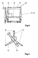
- a specific embodiment for leak detection in a sewage system 4 initially consists of two star-shaped holders 11, which are connected to each other via a support member 10.
- Each of the star-shaped Brackets 11 has 3 at an angle of 120 degrees angle to each other arranged radial parts 12, which are designed telescopically extendable.
- a radial part 12 of a star-shaped holder 11 is associated with the another radial part 12 of the second star-shaped holder 11 via a U-shaped connecting part 14 connected to each other, so that the two star-shaped brackets 11 are fixed to each other.
- Each of the U-shaped connecting parts 14 contributes to the wall of the examining sewage system facing side rollers 16, thus allowing unobstructed Warping the device in the sewage system is possible and a All-round leadership is given.
- telescopically extendable radial parts 12 can be the outer Diameter of the device to the inner diameter of the examined Adapt sewage system, allowing a continuous guidance of the overall arrangement is adjustable in the sewage system.
- At one of the two star-shaped holders 11 is a in the radial direction extending telescopic arm 15 is arranged. This one wears on its exterior End of the transducer 8, due to the arrangement on the telescopic arm 15 can be placed in a position in the immediacy lies to the walls of the sewage system. Furthermore, in the star-shaped Holder 11, to which the telescopic arm 15 is attached, a rotator 14th integrated, the radially arranged telescopic arm 15 in a continuous Rotated motion offset. On the support member 10 are further necessary individual elements attached. This can be, for example, the data logger that can however, also be an antenna for the transducer, with their help obtained data are forwarded to a registration unit.
- Telescopic arm 15 and radial parts 12 On the representation of elements for clamping the telescopic adjustment Telescopic arm 15 and radial parts 12 has been omitted.
Landscapes
- Physics & Mathematics (AREA)
- General Physics & Mathematics (AREA)
- Examining Or Testing Airtightness (AREA)
- Investigating Or Analyzing Materials By The Use Of Electric Means (AREA)
Abstract
Description
- Fig. 1
- die Ausbildung einer erfindungsgemässen Anordnung bei der Leckageortung eines teilweise unterirdisch angeordneten Einbaus, wie das bei einer Tiefgarage der Fall ist,
- Fig. 2
- die ausgeschriebene Kurve der Feldänderungen für die beispielhafte Darstellung gemäss Fig. 1,
- Fig. 3
- die prinzipielle Ausbildung einer erfindungsgemässen Anordnung bei der Leckageortung in einem Abwassersystem.
- Fig. 4
- eine spezifische Ausführungsform einer Anordnung, die zur Leckageortung in einem rohrförmigen Körper dient, in der Seitenansicht,
- Fig. 5
- die Vorderansicht der Fig. 4.
- Erdreich
- 1
- Bodenplatte
- 2
- Seitenwand
- 3
- Grundwasser-Markierung
- 4
- Elektrode
- 5
- Gegenpol
- 6
- Stromquelle
- 7
- Messwertaufnehmer
- 8
- Undichtheiten
- 9/1, 9/2, 9/3, 9/4, 9/5, 9/6
- Wasserdurchtrittsstellen
- W1, W2, W3, W4
- Trageteil
- 10
- sternförmige Halterung
- 11
- Radialteil
- 12
- Verbindungsteil
- 13
- Rotator
- 14
- Teleskoparm
- 15
- Rollen
- 16
- Datenlogger
- 17
Claims (27)
- Verfahren zur Feststellung von Leckagen in als absperrende Einrichtungen wie Dichtungswänden, Wandungen von Erdtanks, Grundbauwerken, medienführenden Unterwasserleitungen und dergleichen wirkenden baulichen Einheiten, bei dem zwischen wenigstens zwei Polen ein konstantes elektrisches Feld erzeugt wird, durch wenigstens zwei Koordinaten bestimmt der Feldlinienverlauf festgestellt, Anomalien des Feldlinienverlaufes festgestellt und als Grundlage der Bewertung der Dichtheit der baulichen Einheit zur Verfügung gestellt werden.
- Verfahren nach Anspruch 1, bei dem der das elektrische Feld erzeugende Strom ständig an der Aufgabestelle anliegt.
- Verfahren nach Anspruch 1, bei dem der das elektrische Feld erzeugende Strom gepulst der Aufgabestelle übermittelt wird.
- Verfahren nach einem der Ansprüche 1 bis 3, bei dem die Einzelteile einer Anordnung zur Durchführung des erfindungsgemässen Verfahrens in einem Baustein zusammengefasst, in einem Verdachtsbereich montiert und die Leckageverhältnisse über einen vorbestimmten Zeitraum aufgezeichnet und der Auswertung ständig zur Verfügung gestellt werden.
- Verfahren nach einem der Ansprüche 1 bis 4, dass die ermittelten Werte der elektrischen Feldlinien und ihrer Anomalien per Monotoring ausgewiesen werden.
- Anordnung zur Durchführung des Verfahrens nach einem der Ansprüche 1 bis 5, bestehend aus wenigstens je einer als Aufgabestelle dienenden und einer weiteren als Abgreifstelle dienenden Elektrode (5; 6), beide elektrisch leitend ausgeführt und mit einer Stromquelle (7) verbunden sind, unter Bezugnahme auf eine auf Dichtheit zu untersuchende bauliche Einheit die eine auf der Seite eines möglichen Feuchtezutritts, die andere auf der Seite angordnet ist, auf der ein Feuchtezutritt wahrgenommen wird, zwischen den zur Auswertefläche projizierten Abständen von Aufgabestelle und Abgreifstelle räumlich bewegbar ein aus Sensor und Datenlogger (17) bestehender Messwertaufnehmer (8) und mit einer der beiden Elektroden (5; 6) elektrisch/elektronisch verbunden angeordnet ist, der in der Nähe von als relevant zuordenbaren Bereichen plaziert ist und dort wahrnehmbare Werte für das vorhandene elektrische Feld aufnehmend und mit den an der Elektrode (5; 6) anliegenden Werten vergleichend ausgebildet ist, mit der der Messwertaufnehmer (8) verbunden angeordnet ist.
- Anordnung nach Anspruch 6, bei der der Messwertaufnehmer (8) für eine Leckagefeststellung in einem rohrförmigen Körper auf einem Schlitten angeordnet ist, der in Längsrichtung des zu untersuchenden rohrförmigen Körpers eine Längsausdehnung aufweist, im weiteren aus zueinander beabstandeten und miteinander in Richtung der Mittellängsachse wenigstens zwei sternförmigen Halterungen (11) gleicher Teilung besteht, die symmetrisch zueinander angeordnet sind und die in identischer Teilung strahlenförmig angeordnet Radialteile (12) aufweisen, die bezogen auf die sternförmigen Halterungen (11) gleicher Teilung symmetrisch zueinander ausgebildet sind, die Enden der strahlenförmig angeordneten Radialteile (12) der sternförmigen Halterungen brückenartig durch jeweils ein U-förmig ausgebildetes Verbindungsteil (13) paarweise miteinander verbunden sind, wenigstens einem der beiden Radialteile in Richtung der gedachten Mittellängsachse des Schlittens an einer freien Stirnseite ein Rotator (14) mit einem weiteren Teleskoparm (15) in radialer Richtung sich erstreckend vorgesetzt, der an seinem vom Rotator (14) entfernten Ende eine Halterung für den Messwertaufnehmer (8) und der Schlitten einen Antrieb für die Initiierung einer Drehbewegung des Rotators (14) aufweisend ausgebildet ist.
- Anordnung nach Anspruch 7, bei der die sternförmige Halterung (11) 3 strahlenförmige Radialteile (12) aufweisend ausgebildet ist.
- Anordnung nach Anspruch 8, bei der die strahlenförmigen Radialteile (12) im Winkel von 120 Winkelgrad angeordnet sind.
- Anordnung nach einem der Ansprüche 7 bis 9, bei der die Radialteile (12) in radialer Richtung teleskopisch ausgebildet sind.
- Anordnung nach einem der Ansprüche 7 bis 10, bei der die dem zu untersuchenden rohrförmigen Körper zugewandte Aussenseite der U-förmig ausgebildeten Verbindungsteile (13) Rollen tragend ausgebildet ist.
- Anordnung nach einem der Ansprüche 7 bis 11, bei der in Richtung der Mittellängsachse des Schlittens die sternförmigen Halterungen (11) verbindend ein Trageteil (10) vorhanden ist.
- Anordnung nach Anspruch 12, bei der das Trageteil (11) weitere zur Anordnung gehörende Einzelelemente aufnehmend gestaltet ist.
- Anordnung nach einem der Ansprüche 7 bis 13, bei der die Registriereinrichtung die übermittelten Werte punktuell ermittelnd und aufbereitend aufgebaut ist.
- Anordnung nach einem der Ansprüche 7 bis 13, bei der die Registriereinrichtung die übermittelten Werte linienförmig ermittelnd und aufbereitend aufgebaut ist.
- Anordnung nach einem der Ansprüche 14 oder 15, bei der die Registriereinrichtung übermittelte Werte graphisch anzeigend aufgebaut ist.
- Anordnung nach einem der Ansprüche 6 und 14 bis 16, die die Messwerte für die Ermittlung geophysikalischer Kennwerte bereitstellend und aufbereitend aufgebaut ist.
- Anordnung nach einem der Ansprüche 6 bis 17, bei der wenigstens eine der als Aufgabestelle und als Abgreifstelle dienenden Elektroden (5; 6) einen ortungsfähigen Baustein aufweisend ausgebildet sind.
- Anordnung nach einem der Ansprüche 6 bis 18, bei der die Elektroden (5; 6) mit einer als Sensor ausgebildeten Empfangseinrichtung elektrisch / elektronisch gekoppelt sind.
- Anordnung nach einem der Ansprüche 6 bis 18, bei der die Elektroden (5; 6) als Sensor ausgebildet sind.
- Anordnung nach einem der Ansprüche 6 bis 20, bei der die Stromquelle (7) eine transportable Einrichtung zur Pufferung des elektrischen Stromes ist.
- Anordnung nach einem der Ansprüche 6 bis 21, bei der der Messwertaufnehmer (8) eine Momentananzeige aufweisend ausgebildet ist.
- Anordnung nach einem der Ansprüche 6 bis 22, bei der die die Kennwerte des elektrischen Feldes fixierende Registriereinrichtung elektrisch/elektronisch mit einer auslesbaren Einrichtung, die bezogen auf einen zeitlichen Verlauf gemessene Kennwerte speichert, verbunden ist.
- Anordnung nach einem der Ansprüche 6 bis 23, bei der die als Aufgabestelle und als Abgreifstelle dienenden Elektroden (5; 6) unterwasserfähig arbeitend ausgebildet sind.
- Anordnung nach einem der Ansprüche 6 bis 24, bei der die Verbindung wenigstens einer Elektrode (5;6) mit der Registriereinrichtung durch eine funkfähig ausgebildete Einrichtung erfolgt ist.
- Anordnung nach einem der Ansprüche 6 bis 24, bei der die Verbindung wenigstens einer Elektrode (5; 6) mit der Registriereinrichtung durch eine nach dem Prinzip eines Global-Position-Systems arbeitenden Einrichtung erfolgend ausgebildet ist.
- Anordnung nach einem der Ansprüche 6 bis 26, bei der der Messwertaufnehmer (8) rotationsfähig ausgebildet ist.
Applications Claiming Priority (4)
| Application Number | Priority Date | Filing Date | Title |
|---|---|---|---|
| DE10234620 | 2002-07-29 | ||
| DE10234620 | 2002-07-29 | ||
| DE10317073A DE10317073A1 (de) | 2002-07-29 | 2003-04-14 | Verfahren und Anordnung zur Feststellung von Leckagen in einer absperrenden Wandung |
| DE10317073 | 2003-04-14 |
Publications (2)
| Publication Number | Publication Date |
|---|---|
| EP1387156A1 true EP1387156A1 (de) | 2004-02-04 |
| EP1387156B1 EP1387156B1 (de) | 2006-06-07 |
Family
ID=30116655
Family Applications (1)
| Application Number | Title | Priority Date | Filing Date |
|---|---|---|---|
| EP03017037A Expired - Lifetime EP1387156B1 (de) | 2002-07-29 | 2003-07-28 | Verfahren und Anordnung zur Feststellung von Leckagen in einer absperrenden Wandung |
Country Status (3)
| Country | Link |
|---|---|
| EP (1) | EP1387156B1 (de) |
| AT (1) | ATE329241T1 (de) |
| DE (1) | DE50303652D1 (de) |
Cited By (3)
| Publication number | Priority date | Publication date | Assignee | Title |
|---|---|---|---|---|
| EP1643229A3 (de) * | 2004-10-01 | 2006-07-05 | Texplor Exploration & Environmental Technology GmbH | Vorrichtung und Verfahren zum Überwachen einer Feuchtigkeitssperre |
| CN115928666A (zh) * | 2023-01-06 | 2023-04-07 | 水利部交通运输部国家能源局南京水利科学研究院 | 面板堆石坝水下面板入渗点探测封堵一体化装置及方法 |
| CN115979517A (zh) * | 2022-12-13 | 2023-04-18 | 上海勘察设计研究院(集团)有限公司 | 用于既有建筑物的地下室底板及侧壁渗漏通道的检测方法 |
Families Citing this family (1)
| Publication number | Priority date | Publication date | Assignee | Title |
|---|---|---|---|---|
| US9651448B1 (en) | 2014-12-24 | 2017-05-16 | Lane Enterprises, Inc. | Liner system for detection of leaks or the presence of water |
Citations (4)
| Publication number | Priority date | Publication date | Assignee | Title |
|---|---|---|---|---|
| US2607012A (en) * | 1950-06-10 | 1952-08-12 | Crane Co | Radiographic inspection device |
| DE4219434A1 (de) * | 1992-06-13 | 1993-12-16 | Bernhard Rammner | Verfahren und Vorrichtungen zur Detektierung und Interpretation von Leckagen |
| DE4223752A1 (de) * | 1992-07-18 | 1994-01-20 | Sensor Druzstvo Pre Vyrobu Obc | Vorrichtung zum Feststellen des Undurchlässigkeitszustandes eines Isolationsunterbaus bei Abfalldeponien |
| US5640096A (en) * | 1995-11-08 | 1997-06-17 | Anderson Manufacturing Co. | Elastomer leak detection apparatus |
Family Cites Families (1)
| Publication number | Priority date | Publication date | Assignee | Title |
|---|---|---|---|---|
| AU6685494A (en) * | 1993-06-03 | 1995-01-03 | Apex Data Systems Limited | Method and apparatus for measuring geophysical data |
-
2003
- 2003-07-28 AT AT03017037T patent/ATE329241T1/de active
- 2003-07-28 EP EP03017037A patent/EP1387156B1/de not_active Expired - Lifetime
- 2003-07-28 DE DE50303652T patent/DE50303652D1/de not_active Expired - Lifetime
Patent Citations (4)
| Publication number | Priority date | Publication date | Assignee | Title |
|---|---|---|---|---|
| US2607012A (en) * | 1950-06-10 | 1952-08-12 | Crane Co | Radiographic inspection device |
| DE4219434A1 (de) * | 1992-06-13 | 1993-12-16 | Bernhard Rammner | Verfahren und Vorrichtungen zur Detektierung und Interpretation von Leckagen |
| DE4223752A1 (de) * | 1992-07-18 | 1994-01-20 | Sensor Druzstvo Pre Vyrobu Obc | Vorrichtung zum Feststellen des Undurchlässigkeitszustandes eines Isolationsunterbaus bei Abfalldeponien |
| US5640096A (en) * | 1995-11-08 | 1997-06-17 | Anderson Manufacturing Co. | Elastomer leak detection apparatus |
Cited By (4)
| Publication number | Priority date | Publication date | Assignee | Title |
|---|---|---|---|---|
| EP1643229A3 (de) * | 2004-10-01 | 2006-07-05 | Texplor Exploration & Environmental Technology GmbH | Vorrichtung und Verfahren zum Überwachen einer Feuchtigkeitssperre |
| CN115979517A (zh) * | 2022-12-13 | 2023-04-18 | 上海勘察设计研究院(集团)有限公司 | 用于既有建筑物的地下室底板及侧壁渗漏通道的检测方法 |
| CN115928666A (zh) * | 2023-01-06 | 2023-04-07 | 水利部交通运输部国家能源局南京水利科学研究院 | 面板堆石坝水下面板入渗点探测封堵一体化装置及方法 |
| CN115928666B (zh) * | 2023-01-06 | 2023-08-18 | 水利部交通运输部国家能源局南京水利科学研究院 | 面板堆石坝水下面板入渗点探测封堵一体化装置及方法 |
Also Published As
| Publication number | Publication date |
|---|---|
| EP1387156B1 (de) | 2006-06-07 |
| ATE329241T1 (de) | 2006-06-15 |
| DE50303652D1 (de) | 2006-07-20 |
Similar Documents
| Publication | Publication Date | Title |
|---|---|---|
| DE2431907C3 (de) | Verfahren und Vorrichtung zur Bestimmung von Konzentrationsprofilen flüssiger oder gasförmiger Stoffe längs einer Strecke | |
| EP1913363B1 (de) | Verfahren und vorrichtung zur überwachung und detektierung von beschichtungsdefekten einer erd- oder wasserverlegten rohrleitung | |
| DE69014002T2 (de) | Verfahren zur kontinuierlichen Kontrolle der Funktionstüchtigkeit von unterirdischen metallischen Strukturen und Vorrichtungen zu seiner Realisierung. | |
| EP1052492B2 (de) | Leckdetektoranordnung und -System | |
| DE102013205765B4 (de) | Qualitätssicherungssystem für Schlitzwandfugen | |
| EP1387156B1 (de) | Verfahren und Anordnung zur Feststellung von Leckagen in einer absperrenden Wandung | |
| AT405335B (de) | Vorrichtung und verfahren zur bestimmung von fehlstellen einer rohrleitung für fluide | |
| DE10317073A1 (de) | Verfahren und Anordnung zur Feststellung von Leckagen in einer absperrenden Wandung | |
| DE202018000073U1 (de) | Überwachungssystem für Behälter, Güllekeller, Güllewannen, Güllekanäle und Erdbecken zur Lagerung von Jauche, Gülle und Silagesickersäften und für Behälter von Biogasanlagen | |
| DE20320677U1 (de) | Anordnung zum Feststellen einer Leckage in einer absperrenden Wandung | |
| DE4219434A1 (de) | Verfahren und Vorrichtungen zur Detektierung und Interpretation von Leckagen | |
| DE19612800A1 (de) | Verfahren und Vorrichtung zur Detektierung und Interpretation von Leckagen in leeren nichtmetallenen Rohrleitungen mithilfe elektrischer Leitfähigkeits-Messungen von mit Druckstrahlen hinter die Leckagen injizierten Flüssigkeitsmengen | |
| DE4231882C2 (de) | Verfahren zur Entdeckung eines fehlerhaften Rohres | |
| DE102010021992B4 (de) | Verfahren zur Erkennung von Beschädigungen der Umhüllung von in Erde und/oder in Gewässern verlegten und durch kathodischen Korrosionsschutz geschützten Objekten | |
| DE2944243A1 (de) | Verfahren zum orten einer undichtigkeit in einer vergrabenen rohrleitung | |
| EP1197730B1 (de) | Verfahren zum Bestimmen von Längsprofilen und Vorrichtung zum Durchführen des Verfahrens | |
| DE3586631T2 (de) | Verfahren zum lecknachweis in einem leitungssystem. | |
| EP1605247A1 (de) | Messprobe für die Bestimmung der Korrosionsangriffstiefe sowie Verfahren zur Messung der Korrosionsangriffstiefe und Verwendung einer Messprobe | |
| EP1527234A1 (de) | Verfahren und vorrichtung zur bodenuntersuchung | |
| DE4238738A1 (de) | Verfahren und Vorrichtung zur Detektierung und Interpretation von Leckagen | |
| DE102024000206A1 (de) | Vorrichtung zur Leckageerkennung an Behältern und Rohrleitungen für die Augfnahme und Lagerung von wassergefährdenden Flüssigkeiten | |
| DE102016122032A1 (de) | Verfahren und Vorrichtung zum Bestimmen der Dichtigkeit von vertikal angeordneten Erdschutzrohren | |
| DE19608902C1 (de) | Verfahren und Vorrichtung zum Nachweis von magnetischen Anomalien im Boden | |
| EP3365656A1 (de) | Untergrunddurchlässigkeitsmessgerät | |
| DE69424787T2 (de) | Pressiometer mit zwei Piezometer |
Legal Events
| Date | Code | Title | Description |
|---|---|---|---|
| PUAI | Public reference made under article 153(3) epc to a published international application that has entered the european phase |
Free format text: ORIGINAL CODE: 0009012 |
|
| AK | Designated contracting states |
Kind code of ref document: A1 Designated state(s): AT BE BG CH CY CZ DE DK EE ES FI FR GB GR HU IE IT LI LU MC NL PT RO SE SI SK TR |
|
| AX | Request for extension of the european patent |
Extension state: AL LT LV MK |
|
| 17P | Request for examination filed |
Effective date: 20040305 |
|
| RAP1 | Party data changed (applicant data changed or rights of an application transferred) |
Owner name: TEXPLOR GMBH |
|
| AKX | Designation fees paid |
Designated state(s): AT BE BG CH CY CZ DE DK EE ES FI FR GB GR HU IE IT LI LU MC NL PT RO SE SI SK TR |
|
| 17Q | First examination report despatched |
Effective date: 20040924 |
|
| GRAP | Despatch of communication of intention to grant a patent |
Free format text: ORIGINAL CODE: EPIDOSNIGR1 |
|
| GRAS | Grant fee paid |
Free format text: ORIGINAL CODE: EPIDOSNIGR3 |
|
| GRAA | (expected) grant |
Free format text: ORIGINAL CODE: 0009210 |
|
| AK | Designated contracting states |
Kind code of ref document: B1 Designated state(s): AT BE BG CH CY CZ DE DK EE ES FI FR GB GR HU IE IT LI LU MC NL PT RO SE SI SK TR |
|
| PG25 | Lapsed in a contracting state [announced via postgrant information from national office to epo] |
Ref country code: IE Free format text: LAPSE BECAUSE OF FAILURE TO SUBMIT A TRANSLATION OF THE DESCRIPTION OR TO PAY THE FEE WITHIN THE PRESCRIBED TIME-LIMIT Effective date: 20060607 Ref country code: IT Free format text: LAPSE BECAUSE OF FAILURE TO SUBMIT A TRANSLATION OF THE DESCRIPTION OR TO PAY THE FEE WITHIN THE PRESCRIBED TIME-LIMIT;WARNING: LAPSES OF ITALIAN PATENTS WITH EFFECTIVE DATE BEFORE 2007 MAY HAVE OCCURRED AT ANY TIME BEFORE 2007. THE CORRECT EFFECTIVE DATE MAY BE DIFFERENT FROM THE ONE RECORDED. Effective date: 20060607 Ref country code: FI Free format text: LAPSE BECAUSE OF FAILURE TO SUBMIT A TRANSLATION OF THE DESCRIPTION OR TO PAY THE FEE WITHIN THE PRESCRIBED TIME-LIMIT Effective date: 20060607 Ref country code: CZ Free format text: LAPSE BECAUSE OF FAILURE TO SUBMIT A TRANSLATION OF THE DESCRIPTION OR TO PAY THE FEE WITHIN THE PRESCRIBED TIME-LIMIT Effective date: 20060607 Ref country code: RO Free format text: LAPSE BECAUSE OF FAILURE TO SUBMIT A TRANSLATION OF THE DESCRIPTION OR TO PAY THE FEE WITHIN THE PRESCRIBED TIME-LIMIT Effective date: 20060607 Ref country code: GB Free format text: LAPSE BECAUSE OF FAILURE TO SUBMIT A TRANSLATION OF THE DESCRIPTION OR TO PAY THE FEE WITHIN THE PRESCRIBED TIME-LIMIT Effective date: 20060607 Ref country code: SK Free format text: LAPSE BECAUSE OF FAILURE TO SUBMIT A TRANSLATION OF THE DESCRIPTION OR TO PAY THE FEE WITHIN THE PRESCRIBED TIME-LIMIT Effective date: 20060607 Ref country code: SI Free format text: LAPSE BECAUSE OF FAILURE TO SUBMIT A TRANSLATION OF THE DESCRIPTION OR TO PAY THE FEE WITHIN THE PRESCRIBED TIME-LIMIT Effective date: 20060607 |
|
| REG | Reference to a national code |
Ref country code: GB Ref legal event code: FG4D Free format text: NOT ENGLISH |
|
| REG | Reference to a national code |
Ref country code: CH Ref legal event code: EP |
|
| REG | Reference to a national code |
Ref country code: IE Ref legal event code: FG4D Free format text: LANGUAGE OF EP DOCUMENT: GERMAN |
|
| REG | Reference to a national code |
Ref country code: CH Ref legal event code: NV Representative=s name: ISLER & PEDRAZZINI AG |
|
| REF | Corresponds to: |
Ref document number: 50303652 Country of ref document: DE Date of ref document: 20060720 Kind code of ref document: P |
|
| PG25 | Lapsed in a contracting state [announced via postgrant information from national office to epo] |
Ref country code: MC Free format text: LAPSE BECAUSE OF NON-PAYMENT OF DUE FEES Effective date: 20060731 |
|
| PG25 | Lapsed in a contracting state [announced via postgrant information from national office to epo] |
Ref country code: DK Free format text: LAPSE BECAUSE OF FAILURE TO SUBMIT A TRANSLATION OF THE DESCRIPTION OR TO PAY THE FEE WITHIN THE PRESCRIBED TIME-LIMIT Effective date: 20060907 Ref country code: SE Free format text: LAPSE BECAUSE OF FAILURE TO SUBMIT A TRANSLATION OF THE DESCRIPTION OR TO PAY THE FEE WITHIN THE PRESCRIBED TIME-LIMIT Effective date: 20060907 |
|
| PG25 | Lapsed in a contracting state [announced via postgrant information from national office to epo] |
Ref country code: ES Free format text: LAPSE BECAUSE OF FAILURE TO SUBMIT A TRANSLATION OF THE DESCRIPTION OR TO PAY THE FEE WITHIN THE PRESCRIBED TIME-LIMIT Effective date: 20060918 |
|
| PG25 | Lapsed in a contracting state [announced via postgrant information from national office to epo] |
Ref country code: PT Free format text: LAPSE BECAUSE OF FAILURE TO SUBMIT A TRANSLATION OF THE DESCRIPTION OR TO PAY THE FEE WITHIN THE PRESCRIBED TIME-LIMIT Effective date: 20061107 |
|
| ET | Fr: translation filed | ||
| GBV | Gb: ep patent (uk) treated as always having been void in accordance with gb section 77(7)/1977 [no translation filed] |
Effective date: 20060607 |
|
| REG | Reference to a national code |
Ref country code: IE Ref legal event code: FD4D |
|
| PLBE | No opposition filed within time limit |
Free format text: ORIGINAL CODE: 0009261 |
|
| STAA | Information on the status of an ep patent application or granted ep patent |
Free format text: STATUS: NO OPPOSITION FILED WITHIN TIME LIMIT |
|
| 26N | No opposition filed |
Effective date: 20070308 |
|
| REG | Reference to a national code |
Ref country code: CH Ref legal event code: PCAR Free format text: ISLER & PEDRAZZINI AG;POSTFACH 1772;8027 ZUERICH (CH) |
|
| PG25 | Lapsed in a contracting state [announced via postgrant information from national office to epo] |
Ref country code: GR Free format text: LAPSE BECAUSE OF FAILURE TO SUBMIT A TRANSLATION OF THE DESCRIPTION OR TO PAY THE FEE WITHIN THE PRESCRIBED TIME-LIMIT Effective date: 20060908 |
|
| PG25 | Lapsed in a contracting state [announced via postgrant information from national office to epo] |
Ref country code: EE Free format text: LAPSE BECAUSE OF FAILURE TO SUBMIT A TRANSLATION OF THE DESCRIPTION OR TO PAY THE FEE WITHIN THE PRESCRIBED TIME-LIMIT Effective date: 20060607 Ref country code: BG Free format text: LAPSE BECAUSE OF FAILURE TO SUBMIT A TRANSLATION OF THE DESCRIPTION OR TO PAY THE FEE WITHIN THE PRESCRIBED TIME-LIMIT Effective date: 20060907 |
|
| PG25 | Lapsed in a contracting state [announced via postgrant information from national office to epo] |
Ref country code: HU Free format text: LAPSE BECAUSE OF FAILURE TO SUBMIT A TRANSLATION OF THE DESCRIPTION OR TO PAY THE FEE WITHIN THE PRESCRIBED TIME-LIMIT Effective date: 20061208 Ref country code: TR Free format text: LAPSE BECAUSE OF FAILURE TO SUBMIT A TRANSLATION OF THE DESCRIPTION OR TO PAY THE FEE WITHIN THE PRESCRIBED TIME-LIMIT Effective date: 20060607 |
|
| PG25 | Lapsed in a contracting state [announced via postgrant information from national office to epo] |
Ref country code: CY Free format text: LAPSE BECAUSE OF FAILURE TO SUBMIT A TRANSLATION OF THE DESCRIPTION OR TO PAY THE FEE WITHIN THE PRESCRIBED TIME-LIMIT Effective date: 20060607 |
|
| PGFP | Annual fee paid to national office [announced via postgrant information from national office to epo] |
Ref country code: CH Payment date: 20100714 Year of fee payment: 8 |
|
| PGFP | Annual fee paid to national office [announced via postgrant information from national office to epo] |
Ref country code: LU Payment date: 20100716 Year of fee payment: 8 |
|
| REG | Reference to a national code |
Ref country code: CH Ref legal event code: PL |
|
| PG25 | Lapsed in a contracting state [announced via postgrant information from national office to epo] |
Ref country code: LI Free format text: LAPSE BECAUSE OF NON-PAYMENT OF DUE FEES Effective date: 20110731 Ref country code: CH Free format text: LAPSE BECAUSE OF NON-PAYMENT OF DUE FEES Effective date: 20110731 |
|
| PGFP | Annual fee paid to national office [announced via postgrant information from national office to epo] |
Ref country code: BE Payment date: 20120713 Year of fee payment: 10 Ref country code: FR Payment date: 20120719 Year of fee payment: 10 |
|
| PGFP | Annual fee paid to national office [announced via postgrant information from national office to epo] |
Ref country code: AT Payment date: 20120626 Year of fee payment: 10 |
|
| PG25 | Lapsed in a contracting state [announced via postgrant information from national office to epo] |
Ref country code: LU Free format text: LAPSE BECAUSE OF NON-PAYMENT OF DUE FEES Effective date: 20110728 |
|
| BERE | Be: lapsed |
Owner name: *TEXPLOR G.M.B.H. Effective date: 20130731 |
|
| REG | Reference to a national code |
Ref country code: AT Ref legal event code: MM01 Ref document number: 329241 Country of ref document: AT Kind code of ref document: T Effective date: 20130728 |
|
| REG | Reference to a national code |
Ref country code: FR Ref legal event code: ST Effective date: 20140331 |
|
| PG25 | Lapsed in a contracting state [announced via postgrant information from national office to epo] |
Ref country code: BE Free format text: LAPSE BECAUSE OF NON-PAYMENT OF DUE FEES Effective date: 20130731 |
|
| PG25 | Lapsed in a contracting state [announced via postgrant information from national office to epo] |
Ref country code: FR Free format text: LAPSE BECAUSE OF NON-PAYMENT OF DUE FEES Effective date: 20130731 Ref country code: AT Free format text: LAPSE BECAUSE OF NON-PAYMENT OF DUE FEES Effective date: 20130728 |
|
| REG | Reference to a national code |
Ref country code: DE Ref legal event code: R082 Ref document number: 50303652 Country of ref document: DE Representative=s name: BOEHMERT & BOEHMERT ANWALTSPARTNERSCHAFT MBB -, DE Ref country code: DE Ref legal event code: R081 Ref document number: 50303652 Country of ref document: DE Owner name: TEXPLOR EXPLORATION ENVIRONMENTAL TECHNOLOGY G, DE Free format text: FORMER OWNER: TEXPLOR GMBH, 14482 POTSDAM, DE |
|
| PGFP | Annual fee paid to national office [announced via postgrant information from national office to epo] |
Ref country code: NL Payment date: 20220909 Year of fee payment: 20 Ref country code: DE Payment date: 20220815 Year of fee payment: 20 |
|
| REG | Reference to a national code |
Ref country code: DE Ref legal event code: R071 Ref document number: 50303652 Country of ref document: DE |
|
| REG | Reference to a national code |
Ref country code: NL Ref legal event code: MK Effective date: 20230727 |