EP1387064A2 - Air flap system having magnet spring - Google Patents
Air flap system having magnet spring Download PDFInfo
- Publication number
- EP1387064A2 EP1387064A2 EP03017167A EP03017167A EP1387064A2 EP 1387064 A2 EP1387064 A2 EP 1387064A2 EP 03017167 A EP03017167 A EP 03017167A EP 03017167 A EP03017167 A EP 03017167A EP 1387064 A2 EP1387064 A2 EP 1387064A2
- Authority
- EP
- European Patent Office
- Prior art keywords
- magnet
- magnet element
- movement
- magnetic
- unit
- Prior art date
- Legal status (The legal status is an assumption and is not a legal conclusion. Google has not performed a legal analysis and makes no representation as to the accuracy of the status listed.)
- Withdrawn
Links
Images


Classifications
-
- F—MECHANICAL ENGINEERING; LIGHTING; HEATING; WEAPONS; BLASTING
- F02—COMBUSTION ENGINES; HOT-GAS OR COMBUSTION-PRODUCT ENGINE PLANTS
- F02D—CONTROLLING COMBUSTION ENGINES
- F02D11/00—Arrangements for, or adaptations to, non-automatic engine control initiation means, e.g. operator initiated
- F02D11/06—Arrangements for, or adaptations to, non-automatic engine control initiation means, e.g. operator initiated characterised by non-mechanical control linkages, e.g. fluid control linkages or by control linkages with power drive or assistance
- F02D11/10—Arrangements for, or adaptations to, non-automatic engine control initiation means, e.g. operator initiated characterised by non-mechanical control linkages, e.g. fluid control linkages or by control linkages with power drive or assistance of the electric type
Definitions
- the invention relates to an air damper supply device for controlled feeding of combustion air in an internal combustion engine, in which in a throttle valve housing element a throttle valve member connected to a throttle valve shaft member to be adjusted at least with a reset unit by an actuating movement is.
- On Drive-by-wire system consists of a throttle valve unit and an adjustment unit, which are located together in one housing.
- the throttle valve assembly has at least one throttle valve, which with a throttle valve shaft in the housing is arranged.
- the adjustment unit consists of a motor unit, a return spring and an opening spring, which are arranged on the throttle valve shaft so that a Vehicle in normal operation and in limp home operation if the engine unit fails can move.
- DE 36 31 283 Ai describes a device for the controlled metering of combustion air in an internal combustion engine known in the event of a failure of the electrical Controller on the throttle valve permits emergency operation and freezing of the Throttle valve prevented at rest.
- the throttle valve is connected to an actuating shaft.
- a return spring and a counter spring are arranged on the actuating shaft. While the return spring puts the throttle valve in an end position, the counter spring ensures that the throttle valve is opened to a rest angle and the emergency operation allows.
- DE 41 40 353 A1 describes a device for adjusting the air flow through a Flow body with a throttle valve device for a fuel supply system a vehicle engine with internal combustion known.
- a spring in the housing.
- the spring is also spiral at the beginning and describes an angle of 300 °. Then the spiral part of the Spring into a U-shaped section.
- the spring has a second end, the connects to the U-shaped section.
- the spring works the rotation of the Electric motor counter. Their design ensures that the throttle valve at Failure of the electric motor allows a small passage for emergency operation.
- DE 41 24 973 A1 describes a load adjustment device for a drive machine described in the case of a non-activated actuator a throttle valve under the action of a spring in a determined by an adjustable stop Position is kept outside the normal range.
- a tension spring, a compression spring or a torsion spring can be used.
- the advantages achieved by the invention are in particular that instead of one Spring element now magnetic spring elements are used.
- the magnetic spring element is shatterproof, can be adjusted in terms of its travel so that the Travel is essentially linear in its movement. This is a better one and more precise adjustment possible.
- a first counter-movement unit can be designed so that it can rotate relative to one another at least two magnetic elements with the same magnetic poles lying opposite one another are arranged.
- Such a reset unit replaces the one usually used Return spring that always keeps the throttle valve element in a safe end position emotional.
- a holding magnet element can be used as the first magnetic element of the counter-movement unit arranged on a magnet holding pin positioned in the throttle valve housing element his.
- a movement magnet element can be used as the second magnet element of the counter-movement unit arranged on a magnet holding arm of a toothed ring unit be that can be connected to the throttle valve shaft element.
- the holding and the moving magnet element can be in one or two planes move. This allows the spring characteristics and the spring force to be influenced.
- the countermovement unit can be a third magnetic element, a reinforcing magnetic element have that on the movement magnet element with an opposite magnetic pole can be arranged.
- the holding magnet element and the movement magnet element can be in a spring travel with their south poles facing each other. But it is also possible that they are with facing their north poles. The travel can increase substantially linearly his.
- the reinforcing magnetic element can be with its south pole at the north pole or with its North pole to be arranged on the south pole of the movement magnet element.
- the moving magnet element and the reinforcing magnet element can at least partially molded into the magnetic holding arm.
- the magnetic holding arm and a adjoining ring gear segment of the ring gear unit can at least partially made of plastic. This is an exact positioning and a easy formability of the two magnetic elements.
- a second counter-movement unit can be designed such that it can be moved to each other at least two other magnetic elements with the same magnetic poles are at least partially offset one above the other.
- This reset unit also replaces the limp home spring, which is an emergency operation of the air damper system enabled when the motor drive unit has failed. Besides, will likewise safely avoided that the throttle valve element can freeze.
- a stationary magnet element can be used as the first magnetic element of the second counter-movement unit in a magnet housing element held on a further holding plate be arranged.
- a sliding magnetic element can be used as the second magnetic element of the counter-movement unit movable over the stand magnet element in the magnet housing element and be arranged offset and with a stop arm of a further toothed ring unit, which can be connected to the throttle valve shaft element, in the magnet housing element is to be pushed.
- a repulsion magnet element can be arranged in the stop arm. This will the spring force is increased.
- the holding magnet element, the moving magnet element, the shaft magnet element and the standing magnet element, the first, second and third sliding and the first, second and third standing magnet elements can be square, rectangular, triangular, quadrangular, polygonal, oval, round, ellipsoid or the like. This allows the movement characteristic of this magnet arrangement to be influenced.
- the first, second and third sliding magnet elements can oppose straightening exhibit. This allows the sliding magnet element to be secured against rotation move.
- the movement holding magnet element, the movement element, the shaft magnet element and the standing magnet element can be designed as permanent magnets.
- magnetic materials the materials known to be used are used.
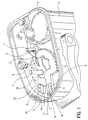
- FIGS. 1-10 An air flap system device is shown in FIGS.
- throttle valve housing element 1 It consists of a throttle valve housing element 1, to which a drive housing 14 is molded.
- a motor housing element 2 is integrally formed in the throttle valve housing element 1.
- a throttle valve element 45 is adjustably arranged in the throttle valve housing element 1 in a throttle valve recess 13 .
- the throttle valve shaft element 4 projects into the drive housing 14.
- the shaft element 4 is a motor unit 15 connected, which can be used in the motor housing element 2.
- a motor holding unit 16 Above the Motor unit 15 is a motor holding unit 16. It is at least partially with a connection unit 20, into which an expansion loop 21 is introduced is.
- a connector unit 22 is arranged on the connection unit 20 at one end is to be inserted into a plug recess 23 in the throttle valve housing element 1.
- connection unit 20 At the opposite end of the connection unit 20 is a Hall effect sensor element 19 arranged, which consists of a stator element 17 with two opposing Stator sub-elements 17.1, 17.2 and an IC element. A magnetic element of the sensor element 19 is molded onto the throttle valve shaft element 4.
- the force of the motor unit 15 on the shaft element is transmitted with the aid of a transmission.
- a gear element 52 a gear pin 7 and a ring gear unit 6, 8 are shown.
- a return spring element 25 is concealed below a turntable 11.
- the throttle valve shaft element is moved by the motor unit 15 and thus opened the throttle valve element 45, the return spring element 25 ensures that the throttle valve element and thus the throttle valve element 45 always in a defined end position (idle position) is moved.
- a moving magnet element 32 is one Magnet holding arm 9 of the sprocket unit held so that its south pole S the south pole S of the holding magnet 31 is opposite.
- the movement magnet element 32 is displaceable held in a pocket of the magnet holding arm 9
- the north pole N of the moving magnet element 32 lies with a north pole N of an amplifier magnetic element 33 North and south poles N, S opposite, so that a counterforce Fi is formed.
- Both Magnetic elements 32, 33 are in the magnetic holding arm 9, which is at least partially made Plastic is molded.
- the holding magnet element 31 lies on the magnet elements 32, 33 in one or two planes across from.
- the throttle valve element 45 can be counter to the counter-spring movement G of the stop pin 5 on which the end of the ring gear segment 6 rests until it moves until the end of the stop arm 8 touches the stop pin 5 strikes.
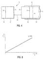
- the spring force can lead to the spring travel 34, which is exponential in the case of cube-shaped magnetic elements, as shown in FIG. 8, be linearized. This is an accurate and fine adjustment of the throttle valve element possible, so that an emergency operation of the vehicle at reduced speed given is. It is particularly advantageous that the magnetic elements are in contrast to work wear-free and unbreakable to springs, so that the air flap system works perfectly in Limp Home mode.
- FIGS. 5 to 7 b A further embodiment of a counter movement unit 12 is shown in FIGS. 5 to 7 b) shown. It consists of a sliding magnet element 121 and an underlying one Stand magnet element 122, which is arranged in a magnet housing element 123.
- the Magnet housing element 123 is held by a holding plate 47.
- the magnetic housing element The stop pin protrudes opposite.
- the holding plate is with connected to the shaft element 4.
- the sliding magnet element 121 has, as shown in particular in FIG. 6, on one side a magnetic south pole S and on the opposite side a magnetic one North pole N on.
- a standing magnet element 122 is opposite the sliding magnet element 121 and arranged at least partially underneath.
- the North Pole N positioned opposite the south pole S of the sliding magnet element.
- both magnetic elements 121, 122 are essentially circular are trained. So that the sliding magnet element can be moved in a straight line can, it is flattened on both sides. The fact that the sliding magnetic element and the standing magnet element 122 are arranged offset from one another, the movement (travel) of the two magnetic elements can be influenced.
- a stop arm 46 which is arranged on the ring gear segment 6, a repulsion magnet element 127 may be arranged.
- FIG. 8 is a spring travel ⁇ of the magnetic elements 121, 122, 127 in a coordinate system represented as a force F as a function of a path S.
- Fig. 8 shows the spring travel ⁇ is a straight line, in particular due to the design of the two magnetic elements 121, 122 is determined as described with reference to FIGS. 4,6,7a and 7b has been.
- the throttle valve element 45 can be moved with the aid of the counter spring movement from the stop pin on which the end of the ring gear segment 6 touch until the end of the stop arm hits the stop pin.
- the travel is, as already linearized. This is a precise and fine adjustment of the Throttle valve element possible, so that an emergency operation of the vehicle with reduced Speed is given. It is particularly advantageous here that the magnetic elements unlike springs work wear-free and shatterproof so that the air flap system works perfectly in limp home mode.
- the magnetic elements are designed similar to a two-piece piece.
- Either a sliding and a standing magnet element 125, 126 have a circular Core as north pole N, around which a ring with at least one south pole S is placed.
- Both Magnetic elements 125, 126 are offset one above the other, so that the spring action like described arises.
- the magnetic elements are designed similar to a 50 cent piece.
- Either a sliding and a standing magnet element, 128, 129 have a circular Core with a north pole N on one side and a south pole S on the other side.
- the two magnetic elements 128, 129 are also offset one above the other, so that the spring action as described arises.
Abstract
Description
Die Erfindung betrifft eine Luftklappenversorgungsvorrichtung zur gesteuerten Zuführung von Verbrennungsluft in eine Brennkraftmaschine, bei der in einem Drosselklappengehäuseelement ein mit einem Drosselklappenwellenelement verbundenes Drosselklappenelement wenigstens mit einer Rückstelleinheit durch eine Stellbewegung zu verstellen ist.The invention relates to an air damper supply device for controlled feeding of combustion air in an internal combustion engine, in which in a throttle valve housing element a throttle valve member connected to a throttle valve shaft member to be adjusted at least with a reset unit by an actuating movement is.
Eine Vorrichtung der eingangs genannten Art ist aus der WO 95 35 440 A2 bekannt. Ein Drive-by-Wire System besteht hierbei aus einer Drosselklappeneinheit und einer Verstelleinheit, die sich gemeinsam in einem Gehäuse befinden. Die Drosselklappeneinheit weist wenigstens eine Drosselklappe auf, die mit einer Drosselklappenwelle im Gehäuse angeordnet ist. Die Verstelleinheit besteht aus einer Motoreinheit, einer Rückstellfeder und einer Öffnerfeder, die an der Drosselklappenwelle so angeordnet sind, daß sich ein Fahrzeug im Normalbetrieb und im Limp-Home-Betrieb bei Ausfall der Motoreinheit bewegen läßt.A device of the type mentioned is known from WO 95 35 440 A2. On Drive-by-wire system consists of a throttle valve unit and an adjustment unit, which are located together in one housing. The throttle valve assembly has at least one throttle valve, which with a throttle valve shaft in the housing is arranged. The adjustment unit consists of a motor unit, a return spring and an opening spring, which are arranged on the throttle valve shaft so that a Vehicle in normal operation and in limp home operation if the engine unit fails can move.
Aus der DE 36 31 283 Ai ist eine Einrichtung zur gesteuerten Zumessung von Verbrennungsluft in eine Brennkraftmaschine bekannt, die im Falle eines Ausfalls des elektrischen Stellers an der Drosselklappe einen Notfahrbetrieb zuläßt und ein Zufrieren der Drosselklappe in der Ruhe verhindert. Die Drosselklappe ist mit einer Stellwelle verbunden. An der Stellwelle ist eine Rückführfeder und eine Gegenfeder angeordnet. Während die Rückstellfeder die Drosselklappe in eine Endstellung stellt, sorgt die Gegenfeder dafür, daß die Drosselklappe in einen Ruhewinkel geöffnet wird und den Notfahrbetrieb ermöglicht.DE 36 31 283 Ai describes a device for the controlled metering of combustion air in an internal combustion engine known in the event of a failure of the electrical Controller on the throttle valve permits emergency operation and freezing of the Throttle valve prevented at rest. The throttle valve is connected to an actuating shaft. A return spring and a counter spring are arranged on the actuating shaft. While the return spring puts the throttle valve in an end position, the counter spring ensures that the throttle valve is opened to a rest angle and the emergency operation allows.
Eine Einrichtung, die ähnlich wie die vorhergenannte aufgebaut ist und ebenfalls zwei Federn einsetzt, ist aus der EP 0 992 662 A2 bekannt.A facility that is constructed similarly to the previous one and also two Use of springs is known from EP 0 992 662 A2.
Diesen drei bekannten Lösungen ist gemeinsam, daß Spiralfedern zum Einsatz kommen, die bruchanfällig sind. Außerdem haben die Spiralfedern eine Federkraft, die exponentiell ansteigt.These three known solutions have in common that spiral springs are used, that are prone to breakage. In addition, the coil springs have a spring force that is exponential increases.
Aus der DE 41 40 353 A1 ist eine Einrichtung zur Einstellung des Luftstroms durch einen Durchstromkörper mit einer Drosselklappeneinrichtung für eine Kraftstoffversorgungsanlage eines Fahrzeugmotors mit interner Verbrennung bekannt. In einem Gehäuse befindet sich eine Feder. Die Feder ist am Anfang gleichfalls spiralförmig ausgebildet und beschreibt einen Winkel von 300°. Danach geht der spiralförmige Teil der Feder in einen U-förmigen Abschnitt über. Die Feder weist ein zweites Ende auf, das sich an den U-förmigen Abschnitt anschließt. Die Feder arbeitet der Drehbewegung des Elektromotors entgegen. Ihre Ausgestaltung sorgt dafür, daß der Drosselschieber bei Ausfall des Elektromotors einen kleinen Durchlaß für einen Notbetrieb ermöglicht.DE 41 40 353 A1 describes a device for adjusting the air flow through a Flow body with a throttle valve device for a fuel supply system a vehicle engine with internal combustion known. In one There is a spring in the housing. The spring is also spiral at the beginning and describes an angle of 300 °. Then the spiral part of the Spring into a U-shaped section. The spring has a second end, the connects to the U-shaped section. The spring works the rotation of the Electric motor counter. Their design ensures that the throttle valve at Failure of the electric motor allows a small passage for emergency operation.
Letztendlich wird in der DE 41 24 973 A1 eine Lastverstelleinrichtung für eine Antriebsmaschine beschrieben, bei der bei einem nicht aktivierten Stellantrieb eine Drosselklappe unter Wirkung einer Feder in einer durch einen einstellbaren Anschlag bestimmten Stellung außerhalb des normalen Stellbereichs gehalten wird. Als Feder soll allerdings eine Zugfeder, eine Druckfeder oder eine Drehfeder zum Einsatz kommen.Ultimately, DE 41 24 973 A1 describes a load adjustment device for a drive machine described in the case of a non-activated actuator a throttle valve under the action of a spring in a determined by an adjustable stop Position is kept outside the normal range. As a feather however, a tension spring, a compression spring or a torsion spring can be used.
Es stellt sich deshalb die Aufgabe, eine Luftklappenversorgungsvorrichtung der eingangs genannten Art so weiterzuentwickeln, daß deren Drosselklappenelement einfach und sicher verstellbar ist.It is therefore the task of an air damper supply device at the beginning mentioned type so that their throttle element is easy and is securely adjustable.
Erfindungsgemäß wird diese Aufgabe durch die Merkmale des Anspruchs 1 gelöst.According to the invention, this object is achieved by the features of claim 1.
Die mit der Erfindung erzielten Vorteile bestehen insbesondere darin, daß anstelle eines Federelements jetzt Magnetfederelemente zum Einsatz kommen. Das Magnetfederelement ist bruchsicher, läßt sich hinsichtlich seines Federweges so einstellen, daß der Federweg im wesentlichen bei seiner Bewegung linear ist. Hierdurch ist eine bessere und genauere Verstellmöglichkeit gegeben.The advantages achieved by the invention are in particular that instead of one Spring element now magnetic spring elements are used. The magnetic spring element is shatterproof, can be adjusted in terms of its travel so that the Travel is essentially linear in its movement. This is a better one and more precise adjustment possible.
Eine erste Gegenbewegungseinheit kann so ausgebildet sein, daß drehbar zueinander wenigstens zwei Magnetelemente mit gleichen magnetischen Polen sich gegenüberliegend angeordnet sind. Eine derartige Rückstelleinheit ersetzt die üblicherweise eingesetzte Rückstellfeder, die das Drosselklappenelement immer in eine sichere Endstellung bewegt.A first counter-movement unit can be designed so that it can rotate relative to one another at least two magnetic elements with the same magnetic poles lying opposite one another are arranged. Such a reset unit replaces the one usually used Return spring that always keeps the throttle valve element in a safe end position emotional.
Als erstes Magnetelement der Gegenbewegungseinheit kann ein Haltemagnetelement an einem im Drosselklappengehäuseelement positionierten Magnethaltezapfen angeordnet sein. Als zweites Magnetelement der Gegenbewegungseinheit kann ein Bewegungsmagnetelement an einem Magnethaltearm einer Zahnkranzeinheit angeordnet sein, die mit dem Drosselklappenwellenelement verbunden sein kann.A holding magnet element can be used as the first magnetic element of the counter-movement unit arranged on a magnet holding pin positioned in the throttle valve housing element his. A movement magnet element can be used as the second magnet element of the counter-movement unit arranged on a magnet holding arm of a toothed ring unit be that can be connected to the throttle valve shaft element.
Das Halte- und das Bewegungsmagnetelement können sich in einer oder zwei Ebenen bewegen. Hierdurch lässt sich die Federcharakteristik und die Federkraft beeinflussen.The holding and the moving magnet element can be in one or two planes move. This allows the spring characteristics and the spring force to be influenced.
Die Gegenbewegungseinheit kann als drittes Magnetelement ein Verstärkungsmagnetelement aufweisen, das an dem Bewegungsmagnetelement mit einem entgegengesetzten magnetischen Pol angeordnet sein kann.The countermovement unit can be a third magnetic element, a reinforcing magnetic element have that on the movement magnet element with an opposite magnetic pole can be arranged.
In einem Federweg können sich das Haltemagnetelement und das Bewegungsmagnetelement mit ihre Südpolen gegenüberliegen. Es ist aber auch möglich, daß sie sich mit ihren Nordpolen gegenüberliegen. Der Federweg kann im wesentlichen linear ansteigend sein.The holding magnet element and the movement magnet element can be in a spring travel with their south poles facing each other. But it is also possible that they are with facing their north poles. The travel can increase substantially linearly his.
Das Verstärkungsmagnetelement kann mit seinem Südpol am Nordpol oder mit seinem Nordpol am Südpol des Bewegungsmagnetelements angeordnet werden. Diese Maßnahmen sorgen dafür, daß bei einer Bewegung des Bewegungsmagnetelements auf das Haltemagnetelement, dieser Bewegung eine Magnetkraft entgegensetzt wird, die eine gleiche rückstellende Wirkung wie eine Federkraft hat.The reinforcing magnetic element can be with its south pole at the north pole or with its North pole to be arranged on the south pole of the movement magnet element. These measures ensure that when moving the moving magnet element on the Holding magnet element, this movement is opposed to a magnetic force, the one has the same restoring effect as a spring force.
Das Bewegungsmagnetelement und das Verstärkungsmagnetelement können wenigstens teilweise in den Magnethaltearm eingeformt sein. Der Magnethaltearm und ein sich daran anschließendes Zahnkranzsegment der Zahnkranzeinheit können wenigstens teilweise aus Kunststoff bestehen. Hierdurch ist eine genaue Positionierung und eine leichte Einformbarkeit der beiden Magnetelemente gegeben.The moving magnet element and the reinforcing magnet element can at least partially molded into the magnetic holding arm. The magnetic holding arm and a adjoining ring gear segment of the ring gear unit can at least partially made of plastic. This is an exact positioning and a easy formability of the two magnetic elements.
Eine zweite Gegenbewegungseinheit kann derart ausgebildet sein, daß verschiebbar zueinander wenigstens zwei weitere Magnetelemente mit gleichen magnetischen Polen wenigstens teilweise versetzt übereinanderliegend angeordnet sind. Diese Rückstelleinheit ersetzt ebenfalls die Limp-Home-Feder, die einen Notbetrieb des Luftklappensystems ermöglicht, wenn die Motorantriebseinheit ausgefallen ist. Außerdem wird gleichfalls sicher vermieden, daß das Drosselklappenelement festfrieren kann.A second counter-movement unit can be designed such that it can be moved to each other at least two other magnetic elements with the same magnetic poles are at least partially offset one above the other. This reset unit also replaces the limp home spring, which is an emergency operation of the air damper system enabled when the motor drive unit has failed. Besides, will likewise safely avoided that the throttle valve element can freeze.
Als erstes Magnetelement der zweiten Gegenbewegungseinheit kann ein Standmagnetelement in einem auf einer weiteren Halteplatte gehaltenen Magnetgehäuseelement angeordnet sein.A stationary magnet element can be used as the first magnetic element of the second counter-movement unit in a magnet housing element held on a further holding plate be arranged.
Als zweites Magnetelement der Gegenbewegungseinheit kann ein Schiebemagnetelement über dem Standmagnetelement in dem Magnetgehäuseelement beweglich und versetzt angeordnet sein und mit einem Anschlagarm einer weiteren Zahnkranzeinheit, die mit dem Drosselklappenwellenelement verbunden sein kann, in das Magnetgehäuseelement zu schieben ist.A sliding magnetic element can be used as the second magnetic element of the counter-movement unit movable over the stand magnet element in the magnet housing element and be arranged offset and with a stop arm of a further toothed ring unit, which can be connected to the throttle valve shaft element, in the magnet housing element is to be pushed.
In dem Anschlagarm kann ein Abstoßmagnetelement angeordnet sein. Hierdurch wird die Federkraft verstärkt.A repulsion magnet element can be arranged in the stop arm. This will the spring force is increased.
Das Schiebemagnetelement und das Standmagnetelement können
- in einen Nord- und einem diesem gegenüberliegenden Südpol (N, S) geteilt sein,
- einen scheibenförmigen Nordpol aufweisen, um den wenigstens ein Südpol angeordnet ist,
- einen scheibenförmigen Nordpol aufweisen, dem ein scheibenförmigen Südpol gegenüberliegt.
- be divided into a north and a south pole (N, S) opposite this,
- have a disc-shaped north pole, around which at least one south pole is arranged,
- have a disc-shaped north pole, which is opposite a disc-shaped south pole.
Das Haltemagnetelement, das Bewegungsmagnetelement, das Wellenmagnetelement und das Standmagnetelement, das erste, zweite und dritte Schiebe- und das erste, zweite und dritte Standmagnetelement können im Querschnitt quadratisch, rechteckig, dreieckig, viereckig, vieleckig, oval, rund, ellipsoid oder dergleichen ausgebildet sein. Hierdurch läßt sich die Bewegungskennlinie dieser Magnetanordnung beeinflussen.The holding magnet element, the moving magnet element, the shaft magnet element and the standing magnet element, the first, second and third sliding and the first, second and third standing magnet elements can be square, rectangular, triangular, quadrangular, polygonal, oval, round, ellipsoid or the like. This allows the movement characteristic of this magnet arrangement to be influenced.
Das erste, zweite und dritte Schiebemagnetelement können sich gegenüberliegende Begradigungen aufweisen. Hierdurch lässt sich das Schiebemagnetelement verdrehungssicher verschieben.The first, second and third sliding magnet elements can oppose straightening exhibit. This allows the sliding magnet element to be secured against rotation move.
Das Bewegungshaltemagnetelement, das Bewegungselement, das Wellenmagnetelement und das Standmagnetelement können als Dauermagnete ausgebildet werden. Als Magnetwerkstoffe kommen die bekannterweise verwendeten Werkstoffe zum Einsatz.The movement holding magnet element, the movement element, the shaft magnet element and the standing magnet element can be designed as permanent magnets. As magnetic materials the materials known to be used are used.
Die Erfindung ist in der Zeichnung dargestellt und wird im folgenden näher erläutert.
Es zeigen
- Fig. 1
- ein Luftklappensystem mit einer Gegenbewegungseinheit als Magnetstellfeder in einer schematischen, perspektivischen Darstellung,
- Fig. 2
- ein Luftklappensystem gemäß Fig. 1 in einer teilweise auseinandergezogenen Darstellung von oben gesehen,
- Fig. 3
- ein Luftklappensystem gemäß Fig. 1 in einer teilweise auseinandergezogenen Darstellung seitlich von unten gesehen,
- Fig. 4
- eine Gegenbewegungseinheit als Magnetstellfeder für ein Luftklappensystem
gemäß den Fig. 1
bis 3 in einer schematisch dargestellten Teildraufsicht, - Fig. 5
- ein Luftklappensystem mit einer weiteren Ausführungsform einer Gegenbewegungseinheit in einer schematischen, perspektivischen Teildarstellung,
- Fig. 6
- eine erste Ausführungsform einer Magnetanordnung für eine Gegenbewegungseinheit gemäß Fig. 5 in einer schematischen, perspektivischen Teildarstellung
- Fig. 7a)
- eine zweite Ausführungsform einer Magnetanordnung für eine Gegenbewegungseinheit gemäß Fig. 5 in einer schematischen, perspektivischen Teildarstellung,
- Fig. 7b)
- eine dritte Ausführungsform einer Magnetanordnung für eine Gegenbewegungseinheit gemäß Fig. 5 in einer schematischen, perspektivischen Teildarstellung und
- Fig. 8
- einen Federweg einer Gegenbewegungseinheit gemäß Fig. 1
bis 4 und Fig. 5bis 6 bzw. 7 als Funktion einer Federkraft in Abhängigkeit vom Weg.
Show it
- Fig. 1
- an air flap system with a counter movement unit as a magnetic spring in a schematic, perspective view,
- Fig. 2
- 1 in a partially exploded view seen from above,
- Fig. 3
- 1 in a partially exploded view seen laterally from below,
- Fig. 4
- 1 shows a countermovement unit as a magnetic actuating spring for an air flap system according to FIGS. 1 to 3 in a schematically illustrated partial top view,
- Fig. 5
- an air flap system with a further embodiment of a counter movement unit in a schematic, perspective partial representation,
- Fig. 6
- a first embodiment of a magnet arrangement for a countermovement unit according to FIG. 5 in a schematic, partial perspective view
- 7a)
- 5 shows a second embodiment of a magnet arrangement for a counter-movement unit according to FIG. 5 in a schematic, perspective partial illustration,
- 7b)
- a third embodiment of a magnet arrangement for a countermovement unit according to FIG. 5 in a schematic, partial perspective view and
- Fig. 8
- a spring travel of a countermovement unit according to FIGS. 1 to 4 and FIGS. 5 to 6 or 7 as a function of a spring force depending on the path.
In den Fig. 1 bis 3 ist eine Luftklappensystemvorrichtung gezeigt.An air flap system device is shown in FIGS.
Sie besteht aus einem Drosselklappengehäuseelement 1, an das ein Antriebsgehäuse 14
angeformt ist. In das Drosselklappengehäuseelement 1 ist ein Motorgehäuseelement 2
angeformt.It consists of a throttle valve housing element 1, to which a drive housing 14 is molded. A
Im Drosselklappengehäuseelement 1 ist in einer Drosselklappenausnehmung 13 mit
einem Drosselklappenwellenelement 4 ein Drosselklappenelement 45 verstellbar angeordnet.
Das Drosselklappenwellenelement 4 ragt in das Antriebsgehäuse 14 hinein.In the throttle valve housing element 1 is in a throttle valve recess 13
a
Wie insbesondere die Fig. 2 und 3 zeigen, ist mit dem Wellenelement 4 eine Motoreinheit
15 verbunden, die in das Motorgehäuseelement 2 eingesetzt werden kann. Über der
Motoreinheit 15 befindet sich eine Motorhalteeinheit 16. Sie ist wenigstens teilweise mit
einer Verbindungseinheit 20 verbunden, in die eine Dehnungsschleife 21 eingebracht
ist.As shown in particular in FIGS. 2 and 3, the
An der Verbindungseinheit 20 ist an einem Ende eine Steckereinheit 22 angeordnet, die
in eine Steckerausnehmung 23 in dem Drosselklappengehäuseelement 1 einzusetzen ist.A
Am gegenüberliegenden Ende der Verbindungseinheit 20 ist ein Hall-Effekt-Sensorelement
19 angeordnet, das aus einem Statorteilelement 17 mit zwei sich gegenüberliegenden
Statorteilelementen 17.1, 17.2 und einem IC-Element besteht. Ein Magnetelement
des Sensorelements 19 ist am Drosselklappenwellenelement 4 angeformt.At the opposite end of the
Die Kraft der Motoreinheit 15 auf das Wellenelement wird mit Hilfe eines Getriebes
übertragen. Von diesem Getriebe ist ein Zahnradelement 52, ein Getriebezapfen 7 und
eine Zahnkranzeinheit 6, 8 gezeigt.The force of the
Unterhalb eines Drehtellers 11 ist verdeckt ein Rückholfederelement 25 angeordnet.
Wird durch die Motoreinheit 15 das Drosselklappenwellenelement bewegt und damit
das Drosselklappenelement 45 geöffnet, sorgt das Rückholfederelement 25 dafür, daß
das Drosselklappenwellenelement und damit das Drosselklappenelement 45 immer in
eine definierte Endstellung (Leerlaufstellung) bewegt wird.A
Erfindungswesentlich ist, daß mit Hilfe dieser Zahnkranzeinheit durch eine Gegenbewegungseinheit
3 das Drosselklappenelement in einer bestimmten Endstellung (Limp-Home-Stellung)
gehalten wird. Während mit Hilfe des Rückholfederelements 25 durch
eine Rückstellbewegung R das Drosselklappenwellenelement 4 in eine Endstellung
(Leerlaufstellung) zurückgestellt wird, wird hierdurch eine Gegenfederbewegung G mit
Hilfe der Gegenbewegungseinheit 3 das Drosselklappenelement in der anderen Endstellung
in einem Öffnungswinkel offengehalten. Und zwar drückt hierbei das Ende eines
Zahnkranzsegments 6 der Zahnkranzeinheit an einen Anschlagzapfen 5, der auf
einer Halteplatte 24 gehalten wird.It is essential to the invention that with the aid of this toothed ring unit by means of a
Das wird dadurch erreicht, daß an einem auf der Halteplatte 24 positionierten Magnethaltezapfen
10 ein Haltemagnetelement 31 mit Nord- und Südpol N, S so angeordnet ist,
daß es mit seinem Südpol S in einen freien Raum zeigt.This is achieved in that on a magnetic holding pin positioned on the holding
Auf der gegenüberliegenden Seite wird ein Bewegungsmagnetelement 32 von einem
Magnethaltearm 9 der Zahnkranzeinheit so gehalten, daß dessen Südpol S dem Südpol
S des Haltemagneten 31 gegenüberliegt. Das Bewegungsmagnetelement 32 ist verschieblich
in einer Tasche des Magnethaltearms 9 gehalten Der Nordpol N des Bewegungsmagnetelement
32 liegt einem Nordpol N eines Verstärkermagnetelements 33 mit
Nord- und Südpol N, S gegenüber, so daß eine Gegenkraft Fi ausgebildet wird. Beide
Magnetelemente 32, 33 sind in den Magnethaltearm 9, der wenigstens teilweise aus
Kunststoff besteht, eingeformt.On the opposite side, a moving
Das Haltemagnetelement 31 liegt den Magnetelementen 32, 33 in einer oder zwei Ebenen
gegenüber.The holding
Fällt die Motoreinheit 15 aus, läßt sich das Drosselklappenelement 45 entgegen der Gegenfederbewegung
G von dem Anschlagzapfen 5, an dem das Ende Zahnkranzsegments
6 anliegt, soweit bewegen, bis das Ende des Anschlagarms 8 an den Anschlagzapfen 5
anschlägt. Das Magnetelement 32 auf der einen und die Magnetelemente 32, 33 auf der
anderen Seite, von denen das Magnetelement 33 die Magnetkraft des Magnetelements
32 insbesondere die Gegenkraft F1 verstärkt, legen einen Federweg 34 zurück. If the
Durch eine besondere Ausgestaltung der Magnetelemente kann die Federkraft zum Federweg
34, der bei würfelförmigen Magnetelementen exponentiell ist, wie Fig. 8 zeigt,
linearisiert werden. Hierdurch ist eine genaue und feine Einstellung des Drosselklappenelements
möglich, so daß ein Notfahrbetrieb des Fahrzeugs mit verminderter Geschwindigkeit
gegeben ist. Von besonderem Vorteil ist, daß die Magnetelemente im Gegensatz
zu Federn verschleißfrei und bruchsicher arbeiten, so daß das Luftklappensystem
im Limp-Home-Betrieb einwandfrei arbeitet.Due to a special configuration of the magnetic elements, the spring force can lead to the
Eine weitere Ausführungsform einer Gegenbewegungseinheit 12 ist in den Fig. 5 bis 7 b)
gezeigt. Sie besteht aus einem Schiebemagnetelement 121 und einem darunter liegenden
Standmagnetelement 122, das in einem Magnetgehäuseelement 123 angeordnet ist. Das
Magnetgehäuseelement 123 wird von einer Halteplatte 47 gehalten. Dem Magnetgehäuseelement
123 gegenüberliegend ragt der Anschlagzapfen hervor. Die Halteplatte ist mit
dem Wellenelement 4 verbunden.A further embodiment of a
Das Schiebemagnetelement 121 weist, wie insbesondere Fig. 6 zeigt, auf der einen Seite
einen magnetischen Südpol S und auf der gegenüberliegenden Seite einen magnetischen
Nordpol N auf. Dem Schiebemagnetelement 121 ist ein Standmagnetelement 122 gegenüberliegend
und wenigstens teilweise unterliegend angeordnet. Hierbei sind der Nordpol
N dem Südpol S des Schiebemagnetelements gegenüberliegend positioniert.The sliding
Erfindungswesentlich ist, daß beide Magnetelemente 121, 122 im wesentlichen kreisförmig
ausgebildet sind. Damit das Schiebemagnetelement geradlinig verschoben werden
kann, ist es zu beiden Seiten abgeflacht. Dadurch, daß das Schiebemagnetelement
und das Standmagnetelement 122 versetzt zueinander beabstandet angeordnet sind,
läßt sich die Bewegung (Federweg) beider Magnetelemente zueinander beeinflussen.
Auch kann in einen Anschlagarm 46, der an dem Zahnkranzsegment 6 angeordnet ist,
ein Abstoßmagnetelement 127 angeordnet sein.It is essential to the invention that both
In Fig. 8 ist ein Federweg ω der Magnetelemente 121, 122, 127 in einem Koordinatensystem
als eine Kraft F in Abhängigkeit von einem Weg S dargestellt. Wie Fig. 8 zeigt, ist
der Federweg ω eine Gerade, die insbesondere durch die Gestaltung der beiden Magnetelement
121, 122 bestimmt wird, wie sie anhand der Fig. 4,6,7a und 7b beschrieben
wurde. 8 is a spring travel ω of the
Fällt die Motoreinheit 15 aus, läßt sich das Drosselklappenelement 45 mit Hilfe der Gegenfederbewegung
von dem Anschlagzapfen, an dem das Ende Zahnkranzsegments 6
anliegt, soweit bewegen, bis das Ende des Anschlagarms an den Anschlagzapfen anschlägt.
Das Magnetelement 121 auf der einen und das Magnetelement 122 auf der anderen
Seite, wobei das Magnetelement 127 die Kraft verstärkt, legen den Federweg ω
zurück.If the
Durch die besondere Ausgestaltung der Magnetelemente ist der Federweg, wie bereits beschrieben linearisiert worden. Hierdurch ist eine genaue und feine Einstellung des Drosselklappenelements möglich, so daß ein Notfahrbetrieb des Fahrzeugs mit verminderter Geschwindigkeit gegeben ist. Von besonderem Vorteil ist auch hier, daß die Magnetelemente im Gegensatz zu Federn verschleißfrei und bruchsicher arbeiten, so daß das Luftklappensystem im Limp-Home-Betrieb einwandfrei arbeitet.Due to the special design of the magnetic elements, the travel is, as already linearized. This is a precise and fine adjustment of the Throttle valve element possible, so that an emergency operation of the vehicle with reduced Speed is given. It is particularly advantageous here that the magnetic elements unlike springs work wear-free and shatterproof so that the air flap system works perfectly in limp home mode.
In Fig. 7 a) sind die Magnetelemente ähnlich einem Zweieurostück ausgebildet. Sowohl
ein Schiebe- als auch ein Standmagnetelement 125, 126 weisen einen kreisförmigen
Kern als Nordpol N auf, um den sich ein Ring mit wenigstens einem Südpol S legt. Beide
Magnetelemente 125, 126 liegen versetzt übereinander, so daß die Federwirkung wie
beschrieben entsteht.In Fig. 7 a) the magnetic elements are designed similar to a two-piece piece. Either
a sliding and a standing
In Fig. 7 b) sind die Magnetelemente ähnlich einem 50 Centstück ausgebildet. Sowohl
ein Schiebe- als auch ein Standmagnetelement , 128, 129 weisen einen kreisförmigen
Kern mit einem Nordpol N auf der einen und einen Südpol S auf der anderen Seite auf.
Beide Magnetelemente 128, 129 liegen auch hier versetzt übereinander, so daß die Federwirkung
wie beschrieben entsteht.In Fig. 7 b) the magnetic elements are designed similar to a 50 cent piece. Either
a sliding and a standing magnet element, 128, 129 have a circular
Core with a north pole N on one side and a south pole S on the other side.
The two
Claims (21)
Applications Claiming Priority (2)
| Application Number | Priority Date | Filing Date | Title |
|---|---|---|---|
| DE10235049A DE10235049A1 (en) | 2002-07-31 | 2002-07-31 | Air flap system with magnetic spring |
| DE10235049 | 2002-07-31 |
Publications (2)
| Publication Number | Publication Date |
|---|---|
| EP1387064A2 true EP1387064A2 (en) | 2004-02-04 |
| EP1387064A3 EP1387064A3 (en) | 2006-04-26 |
Family
ID=30010541
Family Applications (1)
| Application Number | Title | Priority Date | Filing Date |
|---|---|---|---|
| EP03017167A Withdrawn EP1387064A3 (en) | 2002-07-31 | 2003-07-29 | Air flap system having magnet spring |
Country Status (3)
| Country | Link |
|---|---|
| US (1) | US6779775B2 (en) |
| EP (1) | EP1387064A3 (en) |
| DE (1) | DE10235049A1 (en) |
Families Citing this family (6)
| Publication number | Priority date | Publication date | Assignee | Title |
|---|---|---|---|---|
| DE102008014609A1 (en) * | 2008-03-17 | 2009-09-24 | Continental Automotive Gmbh | Actuator for switching element of an internal combustion engine |
| US20100006788A1 (en) * | 2008-07-09 | 2010-01-14 | Honeywell International Inc. | Valve assembly having magnetically-energized seal mechanism |
| EP3401532B1 (en) * | 2017-05-10 | 2020-07-08 | Vitesco Technologies GmbH | Valve having a throttle flap arranged in a throttle flap connector |
| EP3401534B1 (en) * | 2017-05-10 | 2020-07-08 | Vitesco Technologies GmbH | Valve having a throttle flap arranged in a throttle flap connector |
| EP3401533B1 (en) * | 2017-05-10 | 2020-07-08 | Vitesco Technologies GmbH | Valve having a throttle flap arranged in a throttle flap connector |
| EP3633248A1 (en) * | 2018-10-02 | 2020-04-08 | Continental Automotive GmbH | Valve for controlling exhaust gas or fresh air in a drive unit |
Citations (5)
| Publication number | Priority date | Publication date | Assignee | Title |
|---|---|---|---|---|
| JPH01116255A (en) * | 1987-10-29 | 1989-05-09 | Mitsubishi Motors Corp | Throttle valve opening and closing control mechanism |
| JPH094475A (en) * | 1995-06-22 | 1997-01-07 | Mikuni Corp | Actuator |
| US5752484A (en) * | 1994-06-18 | 1998-05-19 | Ab Elektronik Gmbh | Throttle valve device |
| EP0848481A2 (en) * | 1996-12-13 | 1998-06-17 | Philips Patentverwaltung GmbH | Adjusting device with electrie motor |
| DE10042577A1 (en) * | 2000-08-30 | 2002-03-14 | Siemens Ag | Throttle valve with emergency air supply device in form of solenoid operated valve actuator loosely coupled to alve |
Family Cites Families (8)
| Publication number | Priority date | Publication date | Assignee | Title |
|---|---|---|---|---|
| DE3631283C2 (en) | 1986-09-13 | 1999-11-25 | Bosch Gmbh Robert | Device for the controlled metering of combustion air in an internal combustion engine |
| CN1014174B (en) * | 1989-06-01 | 1991-10-02 | 毛沛琦 | Magnet-valve for fluid conduit |
| DE4124973A1 (en) | 1991-07-27 | 1993-01-28 | Bosch Gmbh Robert | LOAD ADJUSTMENT DEVICE FOR A DRIVE MACHINE |
| DE19504243A1 (en) * | 1994-06-10 | 1995-12-14 | Philips Patentverwaltung | Device for adjusting an actuator |
| JP3511577B2 (en) | 1998-10-06 | 2004-03-29 | 株式会社日立製作所 | Throttle device for internal combustion engine |
| US6244565B1 (en) * | 1999-01-29 | 2001-06-12 | Ford Global Technologies, Inc. | Throttle body shaft axial play control |
| US6173939B1 (en) * | 1999-11-10 | 2001-01-16 | Ford Global Technologies, Inc. | Electronic throttle control system with two-spring failsafe mechanism |
| US6267352B1 (en) * | 1999-11-11 | 2001-07-31 | Ford Global Technologies, Inc. | Electronic throttle return mechanism with default and gear backlash control |
-
2002
- 2002-07-31 DE DE10235049A patent/DE10235049A1/en not_active Withdrawn
-
2003
- 2003-01-31 US US10/357,067 patent/US6779775B2/en not_active Expired - Fee Related
- 2003-07-29 EP EP03017167A patent/EP1387064A3/en not_active Withdrawn
Patent Citations (5)
| Publication number | Priority date | Publication date | Assignee | Title |
|---|---|---|---|---|
| JPH01116255A (en) * | 1987-10-29 | 1989-05-09 | Mitsubishi Motors Corp | Throttle valve opening and closing control mechanism |
| US5752484A (en) * | 1994-06-18 | 1998-05-19 | Ab Elektronik Gmbh | Throttle valve device |
| JPH094475A (en) * | 1995-06-22 | 1997-01-07 | Mikuni Corp | Actuator |
| EP0848481A2 (en) * | 1996-12-13 | 1998-06-17 | Philips Patentverwaltung GmbH | Adjusting device with electrie motor |
| DE10042577A1 (en) * | 2000-08-30 | 2002-03-14 | Siemens Ag | Throttle valve with emergency air supply device in form of solenoid operated valve actuator loosely coupled to alve |
Non-Patent Citations (2)
| Title |
|---|
| PATENT ABSTRACTS OF JAPAN Bd. 013, Nr. 340 (M-857), 31. Juli 1989 (1989-07-31) & JP 01 116255 A (MITSUBISHI MOTORS CORP), 9. Mai 1989 (1989-05-09) * |
| PATENT ABSTRACTS OF JAPAN Bd. 1997, Nr. 05, 30. Mai 1997 (1997-05-30) & JP 09 004475 A (MIKUNI CORP), 7. Januar 1997 (1997-01-07) * |
Also Published As
| Publication number | Publication date |
|---|---|
| US20040021106A1 (en) | 2004-02-05 |
| EP1387064A3 (en) | 2006-04-26 |
| DE10235049A1 (en) | 2004-02-19 |
| US6779775B2 (en) | 2004-08-24 |
Similar Documents
| Publication | Publication Date | Title |
|---|---|---|
| EP0714478A1 (en) | Throttle valve device | |
| DE602004013416T2 (en) | Linear actuator | |
| DE102006007256B4 (en) | Rotation angle detection device | |
| DE1802515A1 (en) | Device for counting sheets of paper such as banknotes | |
| DE602004002664T2 (en) | Throttle device and vehicle | |
| DE102014100036A1 (en) | Locking device for cooling fan assembly | |
| EP1387064A2 (en) | Air flap system having magnet spring | |
| DE60015206T2 (en) | Throttle control device for internal combustion engine | |
| EP1036303A1 (en) | Measuring device for contactless detection of a rotational angle | |
| DE102016210779B4 (en) | Door fitting with a clutch | |
| EP0964137B1 (en) | Throttle valve body | |
| DE60203475T2 (en) | Throttle and throttle | |
| DE102013227079A1 (en) | POSITION DETECTOR | |
| DE102014210455A1 (en) | position sensing device | |
| DE2526260A1 (en) | DETECTING DEVICE FOR COIN CATEGORIES | |
| WO2000029813A1 (en) | Measuring device for the contactless measurement of an angle of rotation | |
| DE19642613C2 (en) | Device and method for controlling the idle speed of an internal combustion engine | |
| DE19512916A1 (en) | Throttle valve device | |
| EP1154239B1 (en) | Angular position sensor | |
| DE10116459B4 (en) | Rotation angle sensor | |
| DE102021204015A1 (en) | Control valve, in particular for a ventilation device, method for operating a control valve and ventilation device with a control valve | |
| DE3735901C2 (en) | Throttle valve control | |
| EP0051231B1 (en) | Electromagnetic holding or release device | |
| DE10334911A1 (en) | Limp home mode automotive carburetor has omega-shaped spring and air flap to regulate air supply | |
| DE19838572A1 (en) | Motor with permanent magnet rotor |
Legal Events
| Date | Code | Title | Description |
|---|---|---|---|
| PUAI | Public reference made under article 153(3) epc to a published international application that has entered the european phase |
Free format text: ORIGINAL CODE: 0009012 |
|
| AK | Designated contracting states |
Kind code of ref document: A2 Designated state(s): AT BE BG CH CY CZ DE DK EE ES FI FR GB GR HU IE IT LI LU MC NL PT RO SE SI SK TR |
|
| AX | Request for extension of the european patent |
Extension state: AL LT LV MK |
|
| PUAL | Search report despatched |
Free format text: ORIGINAL CODE: 0009013 |
|
| AK | Designated contracting states |
Kind code of ref document: A3 Designated state(s): AT BE BG CH CY CZ DE DK EE ES FI FR GB GR HU IE IT LI LU MC NL PT RO SE SI SK TR |
|
| AX | Request for extension of the european patent |
Extension state: AL LT LV MK |
|
| RIC1 | Information provided on ipc code assigned before grant |
Ipc: F02D 11/10 20060101AFI20031029BHEP |
|
| AKX | Designation fees paid | ||
| STAA | Information on the status of an ep patent application or granted ep patent |
Free format text: STATUS: THE APPLICATION IS DEEMED TO BE WITHDRAWN |
|
| 18D | Application deemed to be withdrawn |
Effective date: 20061027 |
|
| REG | Reference to a national code |
Ref country code: DE Ref legal event code: 8566 |