EP1386893A1 - Apparatus and method for curing a fiber, having at least two fiber coating curing stages - Google Patents
Apparatus and method for curing a fiber, having at least two fiber coating curing stages Download PDFInfo
- Publication number
- EP1386893A1 EP1386893A1 EP03016623A EP03016623A EP1386893A1 EP 1386893 A1 EP1386893 A1 EP 1386893A1 EP 03016623 A EP03016623 A EP 03016623A EP 03016623 A EP03016623 A EP 03016623A EP 1386893 A1 EP1386893 A1 EP 1386893A1
- Authority
- EP
- European Patent Office
- Prior art keywords
- coating
- curing
- fiber
- stage
- curing stage
- Prior art date
- Legal status (The legal status is an assumption and is not a legal conclusion. Google has not performed a legal analysis and makes no representation as to the accuracy of the status listed.)
- Granted
Links
- 238000000576 coating method Methods 0.000 title claims abstract description 274
- 239000011248 coating agent Substances 0.000 title claims abstract description 257
- 239000000835 fiber Substances 0.000 title claims abstract description 191
- 238000000034 method Methods 0.000 title claims abstract description 30
- 238000001816 cooling Methods 0.000 claims abstract description 67
- 238000006116 polymerization reaction Methods 0.000 claims abstract description 40
- 239000013307 optical fiber Substances 0.000 claims description 39
- 239000000112 cooling gas Substances 0.000 claims description 9
- 230000000977 initiatory effect Effects 0.000 claims description 8
- 229920006240 drawn fiber Polymers 0.000 claims description 3
- 238000001723 curing Methods 0.000 description 61
- NIXOWILDQLNWCW-UHFFFAOYSA-M Acrylate Chemical compound [O-]C(=O)C=C NIXOWILDQLNWCW-UHFFFAOYSA-M 0.000 description 11
- 230000008901 benefit Effects 0.000 description 11
- 239000000463 material Substances 0.000 description 9
- 238000006243 chemical reaction Methods 0.000 description 8
- 238000009281 ultraviolet germicidal irradiation Methods 0.000 description 8
- 238000003848 UV Light-Curing Methods 0.000 description 6
- 238000013036 cure process Methods 0.000 description 5
- 230000008569 process Effects 0.000 description 5
- 230000000694 effects Effects 0.000 description 4
- 230000006870 function Effects 0.000 description 4
- 230000007246 mechanism Effects 0.000 description 4
- 230000005855 radiation Effects 0.000 description 4
- 238000002474 experimental method Methods 0.000 description 3
- 238000012546 transfer Methods 0.000 description 3
- 238000005033 Fourier transform infrared spectroscopy Methods 0.000 description 2
- 238000002835 absorbance Methods 0.000 description 2
- 238000013459 approach Methods 0.000 description 2
- 238000004132 cross linking Methods 0.000 description 2
- 238000002329 infrared spectrum Methods 0.000 description 2
- 230000001678 irradiating effect Effects 0.000 description 2
- 239000002184 metal Substances 0.000 description 2
- 229920000642 polymer Polymers 0.000 description 2
- 230000002028 premature Effects 0.000 description 2
- 238000000926 separation method Methods 0.000 description 2
- VYPSYNLAJGMNEJ-UHFFFAOYSA-N silicon dioxide Inorganic materials O=[Si]=O VYPSYNLAJGMNEJ-UHFFFAOYSA-N 0.000 description 2
- 238000012360 testing method Methods 0.000 description 2
- 238000010521 absorption reaction Methods 0.000 description 1
- 230000002411 adverse Effects 0.000 description 1
- 230000009286 beneficial effect Effects 0.000 description 1
- 230000006835 compression Effects 0.000 description 1
- 238000007906 compression Methods 0.000 description 1
- 238000010276 construction Methods 0.000 description 1
- 239000002826 coolant Substances 0.000 description 1
- 230000001419 dependent effect Effects 0.000 description 1
- 230000001627 detrimental effect Effects 0.000 description 1
- 238000011161 development Methods 0.000 description 1
- 230000004907 flux Effects 0.000 description 1
- 230000004927 fusion Effects 0.000 description 1
- 239000007789 gas Substances 0.000 description 1
- 230000020169 heat generation Effects 0.000 description 1
- 238000010438 heat treatment Methods 0.000 description 1
- 239000001307 helium Substances 0.000 description 1
- 229910052734 helium Inorganic materials 0.000 description 1
- SWQJXJOGLNCZEY-UHFFFAOYSA-N helium atom Chemical compound [He] SWQJXJOGLNCZEY-UHFFFAOYSA-N 0.000 description 1
- 238000012423 maintenance Methods 0.000 description 1
- 238000004519 manufacturing process Methods 0.000 description 1
- 239000011159 matrix material Substances 0.000 description 1
- 230000008520 organization Effects 0.000 description 1
- 230000000379 polymerizing effect Effects 0.000 description 1
- 238000012545 processing Methods 0.000 description 1
- 239000010453 quartz Substances 0.000 description 1
- 230000004044 response Effects 0.000 description 1
- XLYOFNOQVPJJNP-UHFFFAOYSA-N water Substances O XLYOFNOQVPJJNP-UHFFFAOYSA-N 0.000 description 1
Images





Classifications
-
- C—CHEMISTRY; METALLURGY
- C03—GLASS; MINERAL OR SLAG WOOL
- C03C—CHEMICAL COMPOSITION OF GLASSES, GLAZES OR VITREOUS ENAMELS; SURFACE TREATMENT OF GLASS; SURFACE TREATMENT OF FIBRES OR FILAMENTS MADE FROM GLASS, MINERALS OR SLAGS; JOINING GLASS TO GLASS OR OTHER MATERIALS
- C03C25/00—Surface treatment of fibres or filaments made from glass, minerals or slags
- C03C25/10—Coating
- C03C25/12—General methods of coating; Devices therefor
-
- B—PERFORMING OPERATIONS; TRANSPORTING
- B05—SPRAYING OR ATOMISING IN GENERAL; APPLYING FLUENT MATERIALS TO SURFACES, IN GENERAL
- B05D—PROCESSES FOR APPLYING FLUENT MATERIALS TO SURFACES, IN GENERAL
- B05D3/00—Pretreatment of surfaces to which liquids or other fluent materials are to be applied; After-treatment of applied coatings, e.g. intermediate treating of an applied coating preparatory to subsequent applications of liquids or other fluent materials
- B05D3/02—Pretreatment of surfaces to which liquids or other fluent materials are to be applied; After-treatment of applied coatings, e.g. intermediate treating of an applied coating preparatory to subsequent applications of liquids or other fluent materials by baking
- B05D3/0209—Multistage baking
-
- B—PERFORMING OPERATIONS; TRANSPORTING
- B29—WORKING OF PLASTICS; WORKING OF SUBSTANCES IN A PLASTIC STATE IN GENERAL
- B29C—SHAPING OR JOINING OF PLASTICS; SHAPING OF MATERIAL IN A PLASTIC STATE, NOT OTHERWISE PROVIDED FOR; AFTER-TREATMENT OF THE SHAPED PRODUCTS, e.g. REPAIRING
- B29C35/00—Heating, cooling or curing, e.g. crosslinking or vulcanising; Apparatus therefor
- B29C35/02—Heating or curing, e.g. crosslinking or vulcanizing during moulding, e.g. in a mould
- B29C35/08—Heating or curing, e.g. crosslinking or vulcanizing during moulding, e.g. in a mould by wave energy or particle radiation
- B29C35/10—Heating or curing, e.g. crosslinking or vulcanizing during moulding, e.g. in a mould by wave energy or particle radiation for articles of indefinite length
-
- B—PERFORMING OPERATIONS; TRANSPORTING
- B05—SPRAYING OR ATOMISING IN GENERAL; APPLYING FLUENT MATERIALS TO SURFACES, IN GENERAL
- B05D—PROCESSES FOR APPLYING FLUENT MATERIALS TO SURFACES, IN GENERAL
- B05D2256/00—Wires or fibres
-
- B—PERFORMING OPERATIONS; TRANSPORTING
- B05—SPRAYING OR ATOMISING IN GENERAL; APPLYING FLUENT MATERIALS TO SURFACES, IN GENERAL
- B05D—PROCESSES FOR APPLYING FLUENT MATERIALS TO SURFACES, IN GENERAL
- B05D3/00—Pretreatment of surfaces to which liquids or other fluent materials are to be applied; After-treatment of applied coatings, e.g. intermediate treating of an applied coating preparatory to subsequent applications of liquids or other fluent materials
- B05D3/06—Pretreatment of surfaces to which liquids or other fluent materials are to be applied; After-treatment of applied coatings, e.g. intermediate treating of an applied coating preparatory to subsequent applications of liquids or other fluent materials by exposure to radiation
- B05D3/061—Pretreatment of surfaces to which liquids or other fluent materials are to be applied; After-treatment of applied coatings, e.g. intermediate treating of an applied coating preparatory to subsequent applications of liquids or other fluent materials by exposure to radiation using U.V.
- B05D3/065—After-treatment
- B05D3/067—Curing or cross-linking the coating
-
- B—PERFORMING OPERATIONS; TRANSPORTING
- B29—WORKING OF PLASTICS; WORKING OF SUBSTANCES IN A PLASTIC STATE IN GENERAL
- B29C—SHAPING OR JOINING OF PLASTICS; SHAPING OF MATERIAL IN A PLASTIC STATE, NOT OTHERWISE PROVIDED FOR; AFTER-TREATMENT OF THE SHAPED PRODUCTS, e.g. REPAIRING
- B29C35/00—Heating, cooling or curing, e.g. crosslinking or vulcanising; Apparatus therefor
- B29C35/02—Heating or curing, e.g. crosslinking or vulcanizing during moulding, e.g. in a mould
- B29C35/08—Heating or curing, e.g. crosslinking or vulcanizing during moulding, e.g. in a mould by wave energy or particle radiation
- B29C35/0805—Heating or curing, e.g. crosslinking or vulcanizing during moulding, e.g. in a mould by wave energy or particle radiation using electromagnetic radiation
- B29C2035/0827—Heating or curing, e.g. crosslinking or vulcanizing during moulding, e.g. in a mould by wave energy or particle radiation using electromagnetic radiation using UV radiation
-
- B—PERFORMING OPERATIONS; TRANSPORTING
- B29—WORKING OF PLASTICS; WORKING OF SUBSTANCES IN A PLASTIC STATE IN GENERAL
- B29L—INDEXING SCHEME ASSOCIATED WITH SUBCLASS B29C, RELATING TO PARTICULAR ARTICLES
- B29L2011/00—Optical elements, e.g. lenses, prisms
- B29L2011/0075—Light guides, optical cables
Definitions
- the present invention relates to an apparatus for producing optical fiber and cable wiring; and, more particularly, relates to an apparatus for producing optical fiber and cable wiring which includes drawing, cooling, coating and curing optical fiber and cable wiring.
- U.S. Patent No. 5,092,264 issued to the instant inventor, describes a device to filter out an infrared component of radiation emitted on the fiber by Ultraviolet (UV) curing lamps for the purpose of reducing the heat put into a fiber coating.
- the device consists of a double-walled, quartz center tube placed within the UV curing lamps through which the fiber passes as it is irradiated.
- the annulus of the tube is filled with water to absorb the infrared component, thus potentially speeding up the cure process by keeping the coatings cooler than otherwise would be the case.
- U.S. Patent Nos. 6,338,878 and 6,370,920 also issued to the instant inventor, describe method and apparatus to actively remove heat from the curing coating while the coating is inside the UV lamps in the flux of the irradiation.
- the heat of the cure reaction exotherm and the heat from the irradiators absorbed by the coating is removed by an active crossflow of cooling gas, thus increasing the rate of polymerization.
- both Fusion Systems, Inc., and Iwasaki Electric Co. offer "cold" reflectors or mirrors for UV irradiators.
- the reflectors reduce the infrared component of the radiation which is directed at the fiber coatings during curing. This is accomplished by the mirrors being coated with a deposited layer which reflects the desired UV component but not the infrared.
- Patent Nos. 6,190,483, 5,636,307, and 5,756,165 Additional methods for trying to increase the level of cure in optical fiber coatings can be found in U.S. Patent Nos. 6,190,483, 5,636,307, and 5,756,165.
- Patent No. 6,190,483 the goal is to obtain a good surface cure of the coating followed by a good thru-cure of the coating. To accomplish this the coating is first exposed to an excimer UV light source emitting at a specific wavelength (i.e. 222 nm), then another emitting at a different wavelength (i.e. 308 nm), followed by a mercury-halide bulb emitting a broad spectrum of UV for an in depth cure.
- an excimer UV light source emitting at a specific wavelength (i.e. 222 nm)
- another emitting at a different wavelength i.e. 308 nm
- a mercury-halide bulb emitting a broad spectrum of UV for an in depth cure.
- Patent number 5,765,165 it is recognized that for faster draw speeds above 5 m/sec it is necessary to have additional UV irradiation to maintain the overall UV dose in order to obtain sufficient cure of the primary coating, and this additional irradiation is provided just off-line of the draw tower by irradiating the fiber on the take-up reel, or alternatively provided by irradiating the fiber later as it is removed from the take-up reel in a respooling operation.
- this additional irradiation is provided just off-line of the draw tower by irradiating the fiber on the take-up reel, or alternatively provided by irradiating the fiber later as it is removed from the take-up reel in a respooling operation.
- the compression placed on the incompletely cured coatings by the draw capstan and its belt can deform the coating on the fiber, negatively affecting the geometry and performance of the fiber in optical fiber ribbon and cable structures.
- U.S. Patent number 5,647,884 provides for a capstan belt of sufficiently soft mechanical properties that coating deformation can be reduced, but this apparatus does not address the cure level of the coating.
- the present inventors have found that it is necessary to obtain substantially complete coating cure in-line on the tower, and prior to the capstan, in order to provide optimum coating protection and performance without risking coating deformation by going through the capstan system in an under-cured state.
- these two mechanisms are manipulated by the present invention to accomplish substantially complete cure in-line, on tower, and at high draw speeds.
- the UV curable coating applied to the optical fiber will not completely cure when the coating is above certain temperatures. Therefore, no matter how many UV lamp cure stages are used to cure the optical fiber coatings, the optical fiber coating will not be completely cured when it is at a high temperature. It has also been found that the properties of the coating improve when cured at lower temperatures. It is hard to control the coating temperature because the UV lamps which are used to cure an optical fiber coating increase the temperature of the coating through the absorption of high-intensity UV and infrared (FR) radiation. Additionally, the coating cure process is an exothermic reaction (generating heat).
- the premature exposure of an already irradiated coating to a second irradiation stage causes a sharp increase in the concentration of activated photoinitiator radicals prior to the completion of polymerization initiated by the first cure stage.
- the activated photoinitiator radicals combine with the radicals of the polymerizing species already active in the coating, causing premature termination of the polymerization and thus preventing a complete coating cure. Therefore, to further improve cure rates it is desirable to remove heat from a coating during polymerization and/or allow sufficient time for polymerization to progress between curing stages.
- a first embodiment of the present invention provides a method and apparatus for curing a coated fiber, comprising at least two fiber coating curing stages and a cooling stage
- a second embodiment of the present invention provides a method and apparatus for curing a coated fiber, comprising at least two fiber coating curing stages separated by a specific distance or time.
- the at least two fiber coating curing stages respond to the coated fiber, for providing a partially cured coated fiber, and further respond to a cooled partially cured coated fiber, for further providing a cured coated fiber.
- the cooling stage responds to the partially cured coated fiber, for providing the cooled partially cured coated fiber.
- this embodiment of the present invention provides a method of configuring UV cure lamps to provide a first UV irradiation, allow an initial cure level to be attained reaching the gel point of the coating, then actively removing the heat of the reaction and the heat absorbed from the first UV lamp. This is followed by additional UV exposure to complete the cure of the coatings.
- the advantage is that this allows complete cure of the coatings even at very high draw speeds.
- An efficient coated-fiber cooling tube is necessary to optimize the effect.
- the cooling stage removes heat from an optical fiber coating between UV cure stages so that upon irradiation in subsequent UV cure stages, the optical fiber coating fully cures.
- the method includes the steps of: applying the coating to the optical fiber, passing the coated optical fiber through a first UV cure stage which partially cures the coating, passing a partially cured coated optical fiber through a cooling tube which reduces the temperature of the optical fiber and coating, and then passing the optical fiber through a subsequent UV cure stage.
- This embodiment of the present invention does not seek to prevent the coatings from heating up during the cure process on fiber optic draw towers.
- This embodiment seeks to irradiate the coating material on the fiber in a curing stage, thus initiating the cure reaction, then actively remove the heat generated during the majority of the cure process, and irradiate the material again in a following curing stage to complete the reaction at a fastest possible rate.
- the curing stages are spaced such that polymerization initiated by the first of the curing stages has time to progress to or near completion prior to the initiation of the second curing stage.
- the spacing or time lapse between curing stages is dependent on both the speed of the drawn fiber passing through the curing stages and the distance between the end of the first curing stage and the beginning of the following curing stage.
- the present invention provides a number of advantages. First, some of the UV cure stages may be eliminated. This adds a cost benefit of not requiring the use of additional UV cure stages and the associated equipment costs. Also, the maintenance cost associated with replacing the various component parts of the UV cure lamps are saved. An additional advantage of the invention is that the draw speed may be increased. Another advantage of the present invention is that the cure of the coated fiber can be accomplished to the full extent and with fewer UV lamps than otherwise necessary in the known prior art approaches. It is further noted that the above two embodiments are not wholly independent of each other, and can be combined in various combinations to optimize the coating cure process.
- an embodiment of the present invention can include both an active cooling stage, as well as taking advantage of specific spacing or timing between curing stages to attain an optimal coating cure.
- the present invention is not limited to applications in the fiber optic industry but has widespread applications in all industries requiring optimal polymerization of coatings, coating materials, or any polymeric materials cured by exposure to UV radiation, including but not limited to electrical cables and wiring, etc.
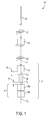
- Figure 1 shows an apparatus in accordance with the first embodiment of the present invention for producing fiber generally indicated as 10.
- the invention consists of a method and apparatus that provides an improved UV curing stage generally indicated as 12 for curing a coated fiber F , comprising at least two fiber coating curing stages 14, 16 and a cooling stage 18.
- the at least two fiber coating curing stages 14 respond to the coated fiber F , for providing a partially cured coated fiber generally indicated as F 1 , and further, respond to a cooled partially cured coated fiber generally indicated as F 2 , for further providing a cured coated fiber generally indicated as F 3 .
- the cooling stage 18 responds to the partially cured coated fiber F 1 , for providing the cooled partially cured coated fiber F 2 .
- the fiber coating curing stage 14 has one or more UV cure lamps.
- the fiber coating curing stage 16 has one or more UV cure lamps indicated as 16(a), 16(b).
- Each of the at least two fiber coating curing stages 14, 16 is separated from the cooling stage 18 by at least a one inch space generally indicated as 15, 17 .
- the at least one inch spaces 15, 17 are entirely open to ambient atmosphere for open air cooling.
- At the one inch space 15 the temperature is in a range of 100-110 degrees Celsius, and at the one inch space 17 the temperature is less than 60 degrees Celsius.
- each of the secondary UV cure lamps 16(a), 16(b) are separated from one another by at least a one inch space.
- the fiber producing apparatus 10 also includes a cooling tube 20 , a primary coater 22 , a primary UV curing stage having a primary UV cure lamp 24 and a secondary coater 26 , which are all known in the art.
- the improved UV curing stage 12 is positioned after the secondary coater 26, which provides the coated fiber F .
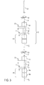
- Figure 3 shows another embodiment in which the improved UV curing stage 12 is also positioned between the primary coater 22 and the secondary coater 26 , as discussed below.
- FIG 2 shows the cooling stage 18 in Figure 1 as an active cooling tube generally indicated as 30.
- the active cooling tube 30 is a hollow tube 32 having tube walls 34 through which a cooling gas flows, as generally indicated by the arrows shown in Figure 2.
- the cooling gas acts as a heat transfer medium from the partially cured coated fiber F 1 to the tube walls 34 of the hollow tube 32.
- the cooling gas is helium, although the scope of the invention is not intended to be strictly limited to only this particular gas.
- the active cooling tube 30 consists of a series of cylindrical hollows generally indicated as 36 in a body of heat conducting metal generally indicated as 38 connected by narrow apertures generally indicated as 40.
- the series of cylindrical hollows 36 and narrow apertures 40 forms a path taken by the partially cured coated fiber F 1 .
- the series of cylindrical hollows 36 have fingers 42 machined in such a way as to increase the surface area of the heat conducting metal 38 for absorbing the heat removed from the partially cured coated fiber F 1 by the cooling gas.
- the series of cylindrical hollows 36 and narrow apertures 40 through which the cooling gas flows provides turbulence to the flow of the cooling gas, thereby increasing the efficiency of heat transfer between the partially cured coated fiber F 1 and the tube walls 34 of the hollow tube 30 .
- FIG 3 shows another embodiment of the improved UV curing stage having an improved UV primary curing stage generally indicated as 50 .
- the improved UV primary curing stage 50 has at least two fiber coating curing stages 14', 16' and a cooling stage 18'.
- One of the at least two fiber coating curing stages responds to a primary coated fiber from the primary coater 22 , for providing a partially cured primary coated fiber.
- the cooling stage responds to the partially cured primary coated fiber F 1 ', for providing a cooled partially cured primary coated fiber.
- the other of the at least two fiber coating curing stages responds to the cooled partially cured primary coated fiber, for providing a cured primary coated fiber to the secondary coater 26.
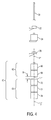
- Figure 4 shows another embodiment of the improved curing stage generally indicated as 60, having at least two fiber coating curing stages 62, 64 .
- the active cooling stage 18 in Figures 1-3 is replaced by a separation between the two fiber coating curing stages 62, 64 of at least a one inch space generally indicated as 76 for cooling a partially cured coated fiber generally indicated as F 1 ''.
- One of the at least two fiber coating curing stages 62 includes two secondary UV cure lamps 66, 68.
- the other of the at least two fiber coating curing stages 64 includes three secondary UV cure lamps 70, 72, 74.
- the at least one inch space 76 is entirely open to ambient atmosphere.
- each of the secondary UV cure lamps 66, 68, 70, 72, 74 are separated from one another by at least a one inch space.
- the improved curing stage 60 consists of positioning the UV lamps 66, 68, 70, 72, 74 in such a way that there is a distance between the lamps 66, 68, 70, 72, 74. This distance may be one inch or more.
- the space between the lamps 66, 68 and lamps 70, 72, 74 may be entirely open to the ambient atmosphere or it may be partially filled with a cooling device such as cooling device 30 in Figure 3.
- the UV lamps 66, 68, 70, 72, 74 are deliberately separated for the purpose of allowing heat to escape from the coatings between UV doses.
- the separation of the UV lamps 66, 68, 70, 72, 74 in Figure 4 and interposition of the active cooling device 18 in Figures 1-3 increase the speed and efficiency of the curing reaction.
- the active cooling tube 18 is designed so as to increase the turbulence of the flow of the cooling gas for increased efficiency of heat transfer from the fiber or the coating.
- Dark-cure time is defined as the period immediately following exposure to a UV lamp during which the polymerization reaction proceeds in the absence of initiating irradiation.
- the optimal cure can be obtained. This is because the polymerization which is begun by the first irradiation is allowed to progress to or near its completion prior to interference from newly formed photoinitiator radicals created by a following irradiation.
- UV lamps were grouped very close to each other in an effort to save space on the draw tower. This would mean that the fiber coating would be irradiated by a second curing stage prior to the progress to or near completion of the polymerization initiated by a preceding curing stage. Essentially what occurs is that the photoinitiator radicals created by the second cure stage interrupt or interfere with the polymerization step that is taking place because of the preceding cure stage.
- the photoinitiator radicals newly created in the second irradiation participate in a combination reaction with the radicals of the growing polymer network and prematurely terminate the growth of the network. This interruption prevents some, if not all, of the initial cross-linking from taking place, thus resulting in an incomplete cure.
- the minimum amount of dark-cure time needed to obtain the benefits of the present invention is approximately at least 40 msec, whereas in prior art configurations the time between cure stages is typically 5 to 10 msec. This is 40 msec of time where the coating is not exposed to any UV irradiation, or the time it takes for a point on the fiber coating to travel from the exit of the first UV lamp to the entrance of the following UV lamp. More preferably, the dark-cure spacing is to be at least approximately 100 msec.
- the optimal time of spacing is at least approximately 100 msec. It is noted that the scope of the present invention is not intended to be limited to a particular maximum time between successive irradiations.
- the types of coating materials used may also affect the optimal length of dark-cure time needed to ensure complete polymerization after the first partial cure, however, the above times are deemed optimal for all commonly known and used coating materials, and the optimum dark-cure times can be changed depending on the coating materials used.
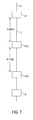
- Figure 5 is diagrammatical representation of the second embodiment of the present invention, where a number of the components shown in Figures 1-4 are not repeated in this Figure to avoid redundancy.
- the drawn fiber F' enters the primary coating unit and the primary coating is initially irradiated by a first primary UV lamp 14'.
- This cure stage initiates polymerization in the coating of the fiber F 1 '.
- This time lapse (which is dependant on distance and draw speed) allows the polymerization initiated by the first curing stage to progress (dark cure) to or near completion before the irradiation by the second curing stage begins.
- the fiber After exiting the second primary UV lamp 16' the fiber then enters a secondary coater 26 to apply a secondary coating.
- Figure 6 is an alternate configuration of the second embodiment of the present invention, where again the coated fiber F 1 ' travels for approximately 200 msec without UV exposure, after the first primary UV lamp 14', and before a second exposure in a second primary UV lamp 16(a)', followed by a third exposure in a third primary UV lamp 16(b)'. It is noted that although the third primary UV lamp 16(b)' is shown shortly following the second primary UV lamp 16(a)' , if space permits, it is contemplated that the time of no UV irradiation of the fiber coating between the second and third irradiation stages could also be increased to optimize cure.
- a time lapse of at least approximately 100 msec is most desirable, however, in this embodiment the distances are optimized taking into account the limited space available. It is also noted that the exact spacing may vary depending on the speed of the traveling fiber and the cure response of the coating materials, and that the optimal dark-cure times should be selected such that the polymerization initiated by the preceding curing stage should progress to or near completion prior to the exposure to a subsequent curing stage.
- Figure 8 discloses an example of UV lamp configuration based on prior art, where the principal objective is to maximize the amount of UV dose delivered to the coatings on the fiber F' while minimizing the space required on the draw tower for the lamp systems.
- the set of lamps for curing the primary coating comprises more than one lamp, and the lamps are stacked as closely together as possible.
- the lamps also typically share a single, long center tube (not shown), a quartz tube inside the UV lamps that is aligned parallel to the direction of the fiber draw process and with the coated fiber traveling down the center of the cross section of this tube. The purpose of this tube is to isolate the coated fiber from the force of the airflow required to cool the UV lamps.
- the coated fiber may have, depending on the draw speed less than 5 msec of time between consecutive exposures to the direct UV irradiation of the stacked lamps.
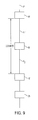
- Figure 9 a portion of a fiber curing apparatus is shown combining both the first and second embodiments of the present invention. It is noted that this Figure is merely intended to demonstrate that the embodiments discussed above may be combined in an effort to optimize fiber coating cure, but is not intended to be limiting in the scope of the present invention in any way. In this Figure, it is shown that the fiber F 1 ' exits the first primary UV lamp 14' and is then cooled by the cooling stage 18' as the polymerization proceeds (dark-cure) to or near completion, the progress aided by removing the exothermic heat during the reaction.
- This cooling stage can be active, and otherwise have the characteristics of the cooling stage previously discussed regarding Figures 1-4. Further, the cooling stage 18' can be placed at any point between the first primary UV lamp 14' and the second primary UV lamp 16'. However, more desirably the cooling stage 18' should be positioned closer to the exit of the first primary UV lamp 14' to remove the exothermic heat of reaction earlier in the polymerization step.
- the fiber F 1 ' After the fiber F 1 ' exits the cooling stage 18' the fiber F 1 ' then enters the second primary UV lamp, which is optimally positioned such that at least approximately 40 msec (and more preferably at least approximately 100 msec) expires between the time at which the fiber F 1 ' exits the first primary UV lamp 14' and the time at which the fiber enters the second primary UV lamp 16'.
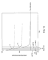
- Figure 10 is a cure graph obtained by Fast Fourier Transform Infrared Spectropscopy (FTIR) showing the relative concentration of unreacted acrylate groups in a fiber coating as a function of time and treatment.
- the graph depicts real time absorbance at the 810 wavenumber peak in the infrared spectrum during the time the coating is irradiated from three successive UV lamps.
- Each of the complete individual curves depicts the cure of acrylate groups as if there is only a single irradiation. However, as shown in this graph, because irradiation from a following lamp interrupts the cure taking place, the final cure level leaves a significant percentage of unreacted acrylate groups in the coating.
- a coating starts with 100% unreacted acrylate groups and is then irradiated by a first lamp for a set amount of time which initiates the cure of a first amount of acrylate groups. If left alone, this cure reaction would proceed as illustrated to asymptotically approach zero rate of chain growth. At that point, although the cure reaction initiated by the first irradiation is substantially complete, much of the original quantity of acrylate groups remains unreacted. Full reaction is not achieved with one irradiation of the primary coating because the polymerization mechanism is in competition with termination mechanisms that eventually bring the process to a halt.
- the third lamp has the same effect on the polymerization initiated by the second lamp, as the second lamp has on the polymerization initiated by the first lamp.
- Figure 11 is a cure graph similar to Figure 10, showing the unreacted acrylate groups in a fiber coating as a function of time in a configuration according to the present invention. The graph also depicts real time absorbance at the 810 wavenumber peak in the infrared spectrum while the coating is irradiated from three UV lamps (as in Figure 10). However, the spacing of the lamps are made in accordance with one embodiment of the present invention showing that the dark-cure polymerization of the first initiated group comes to its substantial completion before the second irradiation occurs (again at point A).
Landscapes
- Life Sciences & Earth Sciences (AREA)
- Health & Medical Sciences (AREA)
- Chemical & Material Sciences (AREA)
- Organic Chemistry (AREA)
- Chemical Kinetics & Catalysis (AREA)
- General Chemical & Material Sciences (AREA)
- Geochemistry & Mineralogy (AREA)
- Materials Engineering (AREA)
- Engineering & Computer Science (AREA)
- General Life Sciences & Earth Sciences (AREA)
- Toxicology (AREA)
- Physics & Mathematics (AREA)
- Oral & Maxillofacial Surgery (AREA)
- Thermal Sciences (AREA)
- Surface Treatment Of Glass Fibres Or Filaments (AREA)
- Optical Fibers, Optical Fiber Cores, And Optical Fiber Bundles (AREA)
Abstract
Description
Moreover, in addition to the adverse effects of heat generation during the curing process, the inventor has discovered that the interruption of polymerization by prematurely exposing the curing coating to a second coating irradiation is detrimental to the achievement of the desired fully-cured condition. Stated differently, it has been discovered that the cure kinetics of coating polymerization requires the polymerization process of an initial cure stage to be progressed as far as possible before initiating a second cure stage. Essentially, the premature exposure of an already irradiated coating to a second irradiation stage causes a sharp increase in the concentration of activated photoinitiator radicals prior to the completion of polymerization initiated by the first cure stage. The activated photoinitiator radicals combine with the radicals of the polymerizing species already active in the coating, causing premature termination of the polymerization and thus preventing a complete coating cure. Therefore, to further improve cure rates it is desirable to remove heat from a coating during polymerization and/or allow sufficient time for polymerization to progress between curing stages.
With regard to Figure 9, a portion of a fiber curing apparatus is shown combining both the first and second embodiments of the present invention. It is noted that this Figure is merely intended to demonstrate that the embodiments discussed above may be combined in an effort to optimize fiber coating cure, but is not intended to be limiting in the scope of the present invention in any way. In this Figure, it is shown that the fiber F1' exits the first primary UV lamp 14' and is then cooled by the cooling stage 18' as the polymerization proceeds (dark-cure) to or near completion, the progress aided by removing the exothermic heat during the reaction. This cooling stage can be active, and otherwise have the characteristics of the cooling stage previously discussed regarding Figures 1-4. Further, the cooling stage 18' can be placed at any point between the first primary UV lamp 14' and the second primary UV lamp 16'. However, more desirably the cooling stage 18' should be positioned closer to the exit of the first primary UV lamp 14' to remove the exothermic heat of reaction earlier in the polymerization step. After the fiber F1' exits the cooling stage 18' the fiber F1' then enters the second primary UV lamp, which is optimally positioned such that at least approximately 40 msec (and more preferably at least approximately 100 msec) expires between the time at which the fiber F1' exits the first primary UV lamp 14' and the time at which the fiber enters the second primary UV lamp 16'.
However, as shown, prior to the cure reaction of these first-initiated groups becoming substantially complete, the irradiation of the coating by the second lamp (at the point A) interrupts the dark-cure polymerization initiated by the first lamp. The second irradiation occurs well before the first polymerization step has approached its limit. The new free radicals (from the second UV cure stage) compete between initiating new polymerization and combining with the existing free radicals on the live ends of the growing polymer network, truncating that growth. The third lamp has the same effect on the polymerization initiated by the second lamp, as the second lamp has on the polymerization initiated by the first lamp.
Figure 11 is a cure graph similar to Figure 10, showing the unreacted acrylate groups in a fiber coating as a function of time in a configuration according to the present invention. The graph also depicts real time absorbance at the 810 wavenumber peak in the infrared spectrum while the coating is irradiated from three UV lamps (as in Figure 10). However, the spacing of the lamps are made in accordance with one embodiment of the present invention showing that the dark-cure polymerization of the first initiated group comes to its substantial completion before the second irradiation occurs (again at point A). With this increased spacing each of the initiated polymerization reactions are allowed to progress to substantial completion before the following initiation. As seen by comparing Figures 10 and 11, the final percentage of unreacted acrylate groups left by the present invention is significantly less than under the prior art methods depicted in Figure 10.
Claims (38)
- An apparatus for curing a coated fiber, comprising:wherein the first and second coating curing stages are spaced apart such that the time it takes for said fiber to pass from an exit of said first coating curing stage to an entrance of said second coating curing stage is at least 40 msec.a first coating curing stage which partially cures a coating of a fiber passing through said first coating curing stage; anda second coating curing stage located on line and downstream of said first coating curing stage to further cure said coating after said fiber exits said first coating curing stage,
- The apparatus according to claim 1, wherein the time between said exit and said entrance is at least 100 msec.
- The apparatus according to claim 1, further comprising a third coating curing stage located downstream of said second coating curing stage for curing said coating.
- The apparatus according to claim 1, further comprising a cooling stage between said first and second coating curing stages.
- The apparatus according to claim 4, wherein said cooling stage is an active cooling stage.
- The apparatus according to claim 1, further comprising a coater located downstream of said second coating curing stage to provide a second coating onto said fiber.
- The apparatus according to claim 6, further comprising a third coating curing stage and a fourth coating curing stage, wherein
said third coating curing stage partially cures said second coating;
said fourth coating curing stage located on-line and downstream of said third coating curing stage further cures said second coating after said fiber exits said third coating curing stage, and
wherein said third and fourth coating curing stages are spaced apart such that the time it takes for said fiber to pass from an exit of said third coating curing stage to an entrance of said fourth coating curing stage is at least 40 msec. - The apparatus according to claim 7, further comprising at least one cooling stage located between either said first and second coating curing stages or said third and fourth coating curing stages.
- The apparatus according to claim 1, wherein said first and second coating curing stages contain ultraviolet lamps for providing ultraviolet light onto said coating.
- The apparatus according to claim 7, wherein said third and fourth coating curing stages contain ultraviolet lamps for providing ultraviolet light onto said second coating.
- A method for curing a coated fiber, comprising:wherein a time lapse of at least 40 msec passes between the time a point on said coating exits said first coating curing stage and said point enters said second coating curing stage.passing a fiber with a coating through a first coating curing stage;partially curing said coating in said first coating curing stage; andpassing said fiber through a second coating curing stage on line and downstream of said first coating curing stage to further cure said coating,
- The method as claimed in claim 11, wherein said time lapse is at least 100 msec.
- The method as claimed in claim 11, further comprising passing said fiber though a third coating curing stage located downstream of said second coating curing stage for curing said coating.
- The method according to claim 11, further comprising passing said fiber through a cooling stage between said first and second coating curing stages.
- The method according to claim 14, wherein said cooling stage actively cools said coating.
- The method according to claim 11, further comprising passing said fiber through a coater located downstream of said second coating curing stage to provide a second coating onto said fiber.
- The method according to claim 16, further comprising passing the fiber through a third coating curing stage and a fourth coating curing stage,
wherein
said third coating curing stage partially cures said second coating;
said fourth coating curing stage located on line and downstream of said third coating curing stage further cures said second coating after said fiber exits said third coating curing stage, and
wherein the time it takes for said fiber to pass from an exit of said third coating curing stage to an entrance of said fourth coating curing stage is at least 40 msec. - An apparatus for curing a coated fiber, comprising:wherein the time it takes for said fiber to pass from an exit of said first coating curing stage to an entrance of said second coating curing stage is sufficient to allow said polymerization initiated by said first coating curing stage to be substantially completed prior to said fiber entering said second coating curing stage.a first coating curing stage which partially cures a coating of a fiber passing through said first coating curing stage, wherein curing of said coating occurs through polymerization; anda second coating curing stage located on line and downstream of said first coating curing stage to further cure said coating after said fiber exits said first coating curing stage,
- The apparatus according to claim 18, wherein the range of time between said exit and said entrance is at least 40 msec.
- The apparatus according to claim 18, further comprising a cooling stage between said first and second coating curing stages.
- A method for curing a coated fiber, comprising:wherein the amount of time elapsed between the exit of a portion of said fiber from said first coating curing stage and said portion entering said second coating curing stage is sufficient to allow said polymerization initiated in said first coating curing stage to be substantially completed prior to said portion entering said second coating curing stage.passing a fiber with a coating through a first coating curing stage to initiate polymerization in said coating;partially curing said coating in said first coating curing stage; andpassing said fiber through a second coating curing stage located on line and downstream from said first curing stage to further cure said coating,
- An apparatus for curing a coated fiber, comprising:wherein the time it takes for said fiber to pass from an exit of said first coating curing stage to an entrance of said second coating curing stage is sufficient to allow said polymerization initiated by said first coating curing stage to be substantially completed prior to said fiber entering said second coating curing stage.a first coating curing stage which partially cures a coating of a fiber passing through said first coating curing stage by initiating polymerization in said coating;a second coating curing stage located on line and downstream of said first coating curing stage to further cure said coating after said fiber exits said first coating curing stage by initiating a additional polymerization in said coating; anda third coating curing stage located on line and downstream of said second coating curing stage to further cure said coating after said exits said first coating curing stage,
- The apparatus according to claim 22, wherein the time it takes for said fiber to pass from an exit of said second coating curing stage to an entrance of said third coating curing stage is sufficient to allow said additional polymerization initiated by said second coating curing stage to be substantially completed prior to said fiber entering said third coating curing stage.
- The apparatus according to claim 22, wherein at least one of said time between said first and second coating curing stages and said time between said second and third coating curing stages is at least 40 msec.
- The apparatus according to claim 23, wherein the times between both said first and second coating curing stages and said second and third coating curing stages are the same.
- The apparatus according to claim 1, wherein the time it takes for said fiber to pass from said exit of said first coating curing stage to said entrance of said second coating curing stage is in a range of 40 msec to 300 msec.
- The method according to claim 11, wherein said time lapse is in the range of 40 msec to 300 msec.
- The method according to claim 17, wherein the time it takes for said fiber to pass from said exit of said third coating curing stage to said entrance of said fourth coating curing stage is in the range of 40 msec to 300 msec.
- The method of claim 21, wherein the amount of said time is at least 40 msec.
- The apparatus of claim 22, wherein said time is at least 40 msec.
- A method for curing a coated fiber, comprising the following steps:providing the coated fiber to a first on line fiber coating curing stage;partially curing said coated fiber with the first fiber coating curing stage, for providing a partially cured coated fiber;cooling the partially cured coated fiber with a cooling device, for providing a cooled partially cured coated fiber; andcuring the cooled partially cured coated fiber with a second on line fiber coating stage located downstream from said first coating curing stage, for providing a cured coated fiber.
- A method of coating and curing a coated fiber, comprising the steps:conveying said optical fiber along a line;coating said optical fiber with a coating using a first coating applicator as said optical fiber is conveyed along said line to provide a coated optical fiber;partially curing said coating with a first on line curing device as said optical fiber is conveyed along said line;cooling said partially cured optical fiber with a cooling device located a predetermined distance from said first curing device as said optical fiber is conveyed along said line;further curing said coating with a second on line curing device as said optical fiber is conveyed along said line, wherein said curing steps cure said coated optical fiber around a periphery of said coated optical fiber.
- A method for curing a coated fiber, comprising the following steps:providing a coated fiber to a first on line fiber coating curing stage;partially curing the coated fiber with the first coating curing stage, for providing a partially cured coated fiber;cooling the partially cured coated fiber with a cooling stage, for providing a cooled partially cured coated fiber; andcuring the cooled partially cured coated fiber with a second on line fiber coating curing stage, for providing a cured coated fiber.
- An apparatus for curing a coated optical fiber, comprising:a first on line coating curing stage, responsive to a coated optical fiber, wherein said first curing stage partially cures a coating of said coated optical fiber;a cooling stage having at least one coating cooling device, responsive to said coated optical fiber after said fiber exits said first curing stage; anda second on line curing stage, responsive to said coated optical fiber after said fiber exits said cooling stage, wherein said second curing stage completely cures said coating of said coated optical fiber.
- An apparatus according to claim 34, wherein said coating cooling device flows a cooling gas across said coated optical fiber.
- A multistage curing, cooling and curing apparatus for curing, cooling and curing a drawn coated fiber, comprising:wherein said curing devices are located along a line of draw of said coated fiber.an on line partial fiber coating curing device, responsive to the coated fiber, for partially curing said coated fiber;an on line active cooling device, located a predetermined distance downstream of said partial fiber coating curing device and responsive to the partially cured coated fiber, for actively cooling the partially cured coated fiber passing through said cooling device, and providing an actively cooled partially cured coated fiber having an actively cooled partially cured coating; andan on line total fiber coating curing device, responsive to the actively cooled partially cured coated fiber, for totally curing said coated fiber,
- A multistage curing, cooling and curing apparatus for curing, cooling and curing a drawn fiber, comprising:an on line primary coater, responsive to the fiber, for providing a primary coated fiber;an on line partial fiber primary coating curing device, responsive to the primary coated fiber, for partially curing said primary coated fiber;an on line active cooling device, located a predetermined distance downstream of said primary coating curing device and responsive to the partially cured primary coated fiber, for actively cooling the partially cured primary coated fiber passing through all around the circumference thereof, and providing an actively cooled partially cured primary coated fiber having an actively cooled partially cured coating all around the primary coated fiber; andan on line total fiber primary coating curing device, responsive to the cooling partially cured primary coated fiber, for totally curing said primary coated fiber having a totally cured primary coating all around the primary coated fiber, wherein said curing devices are located along a line of draw of said fiber.
- An apparatus for coating an optical fiber as said optical fiber moves along a draw line, comprising:a first on line coating applicator for coating said optical fiber with a coating;a first on line curing device, located downstream of said coating applicator, for partially curing said coating;a first on line cooling device, located a predetermined distance downstream of said first curing device, for cooling said partially cured coating;a second on line curing device, located downstream of said first cooling stage, for further curing said coating, wherein said first and second curing devices are located along said draw line such that said coating is cured around an entire periphery thereof.
Applications Claiming Priority (2)
| Application Number | Priority Date | Filing Date | Title |
|---|---|---|---|
| US208861 | 2002-08-01 | ||
| US10/208,861 US7322122B2 (en) | 1997-01-15 | 2002-08-01 | Method and apparatus for curing a fiber having at least two fiber coating curing stages |
Publications (2)
| Publication Number | Publication Date |
|---|---|
| EP1386893A1 true EP1386893A1 (en) | 2004-02-04 |
| EP1386893B1 EP1386893B1 (en) | 2006-05-24 |
Family
ID=30115211
Family Applications (1)
| Application Number | Title | Priority Date | Filing Date |
|---|---|---|---|
| EP03016623A Expired - Lifetime EP1386893B1 (en) | 2002-08-01 | 2003-07-30 | Method for UV-curing a coated fiber |
Country Status (5)
| Country | Link |
|---|---|
| US (1) | US7322122B2 (en) |
| EP (1) | EP1386893B1 (en) |
| AT (1) | ATE327211T1 (en) |
| DE (1) | DE60305390T2 (en) |
| DK (1) | DK1386893T3 (en) |
Cited By (1)
| Publication number | Priority date | Publication date | Assignee | Title |
|---|---|---|---|---|
| CN111433168A (en) * | 2017-12-06 | 2020-07-17 | 株式会社藤仓 | Method and apparatus for manufacturing optical fiber |
Families Citing this family (86)
| Publication number | Priority date | Publication date | Assignee | Title |
|---|---|---|---|---|
| MEP31508A (en) | 2003-07-15 | 2010-10-10 | Amgen Inc | HUMAN ANTI-NGF NEUTRAL ANTIBODIES AS SELECTIVE NGF SIGNAL CASCADE INHIBITORS |
| US20050249390A1 (en) * | 2004-04-29 | 2005-11-10 | Mcclurg George W | Method and apparatus for discriminating ambient light in a fingerprint scanner |
| US8600206B2 (en) * | 2008-11-07 | 2013-12-03 | Draka Comteq, B.V. | Reduced-diameter optical fiber |
| DK2206001T3 (en) * | 2007-11-09 | 2014-07-07 | Draka Comteq Bv | Optical fiber resistant to microbending |
| US8081853B2 (en) * | 2007-11-09 | 2011-12-20 | Draka Comteq, B.V. | Single-fiber drop cables for MDU deployments |
| US8165439B2 (en) * | 2007-11-09 | 2012-04-24 | Draka Comteq, B.V. | ADSS cables with high-performance optical fiber |
| US8031997B2 (en) * | 2007-11-09 | 2011-10-04 | Draka Comteq, B.V. | Reduced-diameter, easy-access loose tube cable |
| US8041167B2 (en) * | 2007-11-09 | 2011-10-18 | Draka Comteq, B.V. | Optical-fiber loose tube cables |
| US8041168B2 (en) * | 2007-11-09 | 2011-10-18 | Draka Comteq, B.V. | Reduced-diameter ribbon cables with high-performance optical fiber |
| US8467650B2 (en) * | 2007-11-09 | 2013-06-18 | Draka Comteq, B.V. | High-fiber-density optical-fiber cable |
| US8145026B2 (en) * | 2007-11-09 | 2012-03-27 | Draka Comteq, B.V. | Reduced-size flat drop cable |
| FR2929716B1 (en) * | 2008-04-04 | 2011-09-16 | Draka Comteq France Sa | OPTICAL FIBER WITH DISPERSION OFFSET. |
| FR2930997B1 (en) | 2008-05-06 | 2010-08-13 | Draka Comteq France Sa | OPTICAL FIBER MONOMODE |
| FR2931253B1 (en) * | 2008-05-16 | 2010-08-20 | Draka Comteq France Sa | FIBER OPTIC TELECOMMUNICATION CABLE |
| FR2932932B1 (en) | 2008-06-23 | 2010-08-13 | Draka Comteq France Sa | MULTIPLEX WAVE LENGTH OPTIC SYSTEM WITH MULTIMODE OPTIC FIBERS |
| FR2933779B1 (en) * | 2008-07-08 | 2010-08-27 | Draka Comteq France | MULTIMODE OPTIC FIBERS |
| US7970247B2 (en) * | 2008-09-12 | 2011-06-28 | Draka Comteq B.V. | Buffer tubes for mid-span storage |
| FR2938389B1 (en) * | 2008-11-07 | 2011-04-15 | Draka Comteq France | MULTIMODE OPTICAL SYSTEM |
| DK2187486T3 (en) * | 2008-11-12 | 2014-07-07 | Draka Comteq Bv | Reinforcing optical fiber and method of manufacture |
| FR2939246B1 (en) * | 2008-12-02 | 2010-12-24 | Draka Comteq France | AMPLIFIER OPTICAL FIBER AND METHOD OF MANUFACTURE |
| FR2939522B1 (en) * | 2008-12-08 | 2011-02-11 | Draka Comteq France | OPTICAL FIBER AMPLIFIER RESISTANT TO IONIZING RADIATION |
| FR2939911B1 (en) * | 2008-12-12 | 2011-04-08 | Draka Comteq France | SOLDERED OPTICAL FIBER, TELECOMMUNICATION CABLE COMPRISING MULTIPLE OPTICAL FIBERS AND METHOD FOR MANUFACTURING SUCH A FIBER |
| NL1036343C2 (en) * | 2008-12-19 | 2010-06-22 | Draka Comteq Bv | METHOD AND APPARATUS FOR MANUFACTURING AN OPTICAL FORM. |
| EP2204681B1 (en) | 2008-12-30 | 2016-03-09 | Draka Comteq B.V. | Optical fibre cable comprising a perforated water-blocking element |
| WO2010077132A1 (en) | 2008-12-31 | 2010-07-08 | Draka Comteq B.V. | Uvled apparatus for curing glass-fiber coatings |
| FR2940839B1 (en) * | 2009-01-08 | 2012-09-14 | Draka Comteq France | INDEX GRADIENT MULTIMODAL OPTICAL FIBER, METHODS FOR CHARACTERIZATION AND MANUFACTURE OF SUCH A FIBER |
| FR2941539B1 (en) * | 2009-01-23 | 2011-02-25 | Draka Comteq France | OPTICAL FIBER MONOMODE |
| FR2941540B1 (en) * | 2009-01-27 | 2011-05-06 | Draka Comteq France | MONOMODE OPTICAL FIBER HAVING ENHANCED EFFECTIVE SURFACE |
| FR2941541B1 (en) * | 2009-01-27 | 2011-02-25 | Draka Comteq France | OPTICAL FIBER MONOMODE |
| US8489219B1 (en) | 2009-01-30 | 2013-07-16 | Draka Comteq B.V. | Process for making loose buffer tubes having controlled excess fiber length and reduced post-extrusion shrinkage |
| US9360647B2 (en) * | 2009-02-06 | 2016-06-07 | Draka Comteq, B.V. | Central-tube cable with high-conductivity conductors encapsulated with high-dielectric-strength insulation |
| FR2942571B1 (en) * | 2009-02-20 | 2011-02-25 | Draka Comteq France | AMPLIFIER OPTICAL FIBER COMPRISING NANOSTRUCTURES |
| FR2942551B1 (en) * | 2009-02-23 | 2011-07-15 | Draka Comteq France | CABLE COMPRISING ELEMENTS TO BE EXTRACTED, METHOD OF EXTRACTING THESE ELEMENTS AND METHOD OF MANUFACTURING THE SAME |
| US8625944B1 (en) | 2009-05-13 | 2014-01-07 | Draka Comteq, B.V. | Low-shrink reduced-diameter buffer tubes |
| US8625945B1 (en) | 2009-05-13 | 2014-01-07 | Draka Comteq, B.V. | Low-shrink reduced-diameter dry buffer tubes |
| FR2946436B1 (en) * | 2009-06-05 | 2011-12-09 | Draka Comteq France | MULTIMODE OPTICAL FIBER WITH LARGE BANDWIDTH WITH AN OPTIMIZED HEAT-SLEEVE INTERFACE |
| US20110026889A1 (en) * | 2009-07-31 | 2011-02-03 | Draka Comteq B.V. | Tight-Buffered Optical Fiber Unit Having Improved Accessibility |
| FR2953606B1 (en) * | 2009-12-03 | 2012-04-27 | Draka Comteq France | MULTIMODE OPTICAL FIBER WITH BROAD BANDWIDTH AND LOW BENDBACK LOSSES |
| FR2957153B1 (en) * | 2010-03-02 | 2012-08-10 | Draka Comteq France | MULTIMODE OPTICAL FIBER WITH BROAD BANDWIDTH AND LOW BENDBACK LOSSES |
| FR2949870B1 (en) * | 2009-09-09 | 2011-12-16 | Draka Compteq France | MULTIMODE OPTICAL FIBER HAVING IMPROVED BENDING LOSSES |
| FR2953029B1 (en) * | 2009-11-25 | 2011-11-18 | Draka Comteq France | MULTIMODE OPTICAL FIBER WITH LARGE BANDWIDTH WITH AN OPTIMIZED HEAT-SLEEVE INTERFACE |
| FR2953030B1 (en) * | 2009-11-25 | 2011-11-18 | Draka Comteq France | MULTIMODE OPTICAL FIBER WITH LARGE BANDWIDTH WITH AN OPTIMIZED HEAT-SLEEVE INTERFACE |
| US9014525B2 (en) | 2009-09-09 | 2015-04-21 | Draka Comteq, B.V. | Trench-assisted multimode optical fiber |
| FR2953605B1 (en) * | 2009-12-03 | 2011-12-16 | Draka Comteq France | MULTIMODE OPTICAL FIBER WITH BROAD BANDWIDTH AND LOW BENDBACK LOSSES |
| US8306380B2 (en) * | 2009-09-14 | 2012-11-06 | Draka Comteq, B.V. | Methods and devices for cable insertion into latched-duct conduit |
| FR2950156B1 (en) * | 2009-09-17 | 2011-11-18 | Draka Comteq France | MULTIMODE OPTIC FIBER |
| FR2950443B1 (en) * | 2009-09-22 | 2011-11-18 | Draka Comteq France | OPTICAL FIBER FOR SUM FREQUENCY GENERATION AND METHOD FOR MANUFACTURING THE SAME |
| US8805143B2 (en) * | 2009-10-19 | 2014-08-12 | Draka Comteq, B.V. | Optical-fiber cable having high fiber count and high fiber density |
| FR2952634B1 (en) * | 2009-11-13 | 2011-12-16 | Draka Comteq France | RARE EARTH DOPED SILICA FIBER WITH LOW DIGITAL OPENING |
| US9042693B2 (en) * | 2010-01-20 | 2015-05-26 | Draka Comteq, B.V. | Water-soluble water-blocking element |
| EP3399357B1 (en) * | 2010-02-01 | 2024-12-11 | Draka Comteq B.V. | Non-zero dispersion shifted optical fiber having a short cutoff wavelength |
| DK2352047T3 (en) * | 2010-02-01 | 2019-11-11 | Draka Comteq Bv | Non-zero dispersion-switched optical fiber with a large effective area |
| EP2369379B1 (en) * | 2010-03-17 | 2015-05-06 | Draka Comteq B.V. | Fibre optique monomode ayant des pertes par courbures réduites |
| US8693830B2 (en) | 2010-04-28 | 2014-04-08 | Draka Comteq, B.V. | Data-center cable |
| PT2390700T (en) | 2010-05-03 | 2016-10-19 | Draka Comteq Bv | PACKAGED OPTICAL FIBER CABLES |
| DK2388239T3 (en) | 2010-05-20 | 2017-04-24 | Draka Comteq Bv | Curing apparatus using angled UV LEDs |
| US8625947B1 (en) | 2010-05-28 | 2014-01-07 | Draka Comteq, B.V. | Low-smoke and flame-retardant fiber optic cables |
| US8871311B2 (en) | 2010-06-03 | 2014-10-28 | Draka Comteq, B.V. | Curing method employing UV sources that emit differing ranges of UV radiation |
| FR2962230B1 (en) | 2010-07-02 | 2012-07-27 | Draka Comteq France | OPTICAL FIBER MONOMODE |
| US8682123B2 (en) | 2010-07-15 | 2014-03-25 | Draka Comteq, B.V. | Adhesively coupled optical fibers and enclosing tape |
| EP2418183B1 (en) | 2010-08-10 | 2018-07-25 | Draka Comteq B.V. | Method for curing coated glass fibres providing increased UVLED intensitiy |
| US8571369B2 (en) | 2010-09-03 | 2013-10-29 | Draka Comteq B.V. | Optical-fiber module having improved accessibility |
| FR2966256B1 (en) | 2010-10-18 | 2012-11-16 | Draka Comteq France | MULTIMODE OPTICAL FIBER INSENSITIVE TO LOSSES BY |
| US8824845B1 (en) | 2010-12-03 | 2014-09-02 | Draka Comteq, B.V. | Buffer tubes having reduced stress whitening |
| DK2482106T5 (en) | 2011-01-31 | 2014-09-22 | Draka Comteq Bv | Multi-mode fiber |
| FR2971061B1 (en) | 2011-01-31 | 2013-02-08 | Draka Comteq France | BROAD BANDWIDTH OPTICAL FIBER WITH LOW CURB LOSSES |
| PT2678728T (en) | 2011-02-21 | 2018-07-05 | Draka Comteq Bv | Fiber Optic Interconnect Cable |
| EP2495589A1 (en) | 2011-03-04 | 2012-09-05 | Draka Comteq B.V. | Rare earth doped amplifying optical fiber for compact devices and method of manufacturing thereof |
| EP2503368A1 (en) | 2011-03-24 | 2012-09-26 | Draka Comteq B.V. | Multimode optical fiber with improved bend resistance |
| EP2506044A1 (en) | 2011-03-29 | 2012-10-03 | Draka Comteq B.V. | Multimode optical fiber |
| EP2518546B1 (en) | 2011-04-27 | 2018-06-20 | Draka Comteq B.V. | High-bandwidth, radiation-resistant multimode optical fiber |
| ES2438173T3 (en) | 2011-05-27 | 2014-01-16 | Draka Comteq Bv | Single mode fiber optic |
| EP2533082B1 (en) | 2011-06-09 | 2013-12-25 | Draka Comteq BV | Single mode optical fiber |
| DK2541292T3 (en) | 2011-07-01 | 2014-12-01 | Draka Comteq Bv | A multimode optical fiber |
| EP2584340A1 (en) | 2011-10-20 | 2013-04-24 | Draka Comteq BV | Hydrogen sensing fiber and hydrogen sensor |
| NL2007831C2 (en) | 2011-11-21 | 2013-05-23 | Draka Comteq Bv | Apparatus and method for carrying out a pcvd deposition process. |
| US9283437B2 (en) | 2011-12-23 | 2016-03-15 | Nike, Inc. | Golf ball having partial cured UV coating |
| US8929701B2 (en) | 2012-02-15 | 2015-01-06 | Draka Comteq, B.V. | Loose-tube optical-fiber cable |
| WO2013160714A1 (en) | 2012-04-27 | 2013-10-31 | Draka Comteq Bv | Hybrid single and multimode optical fiber for a home network |
| US9188754B1 (en) | 2013-03-15 | 2015-11-17 | Draka Comteq, B.V. | Method for manufacturing an optical-fiber buffer tube |
| US20170144930A1 (en) * | 2015-11-20 | 2017-05-25 | Corning Incorporated | Optical fiber production system and method for producing coated optical fiber |
| DE102016100144A1 (en) | 2016-01-05 | 2017-07-06 | J-Fiber Gmbh | Apparatus for coating a fiber and method for coating a fiber and fiber |
| JP6457579B2 (en) * | 2017-04-10 | 2019-01-23 | 株式会社フジクラ | Optical fiber manufacturing method |
| US12344552B2 (en) * | 2021-10-08 | 2025-07-01 | Corning Incorporated | Spacer and methods for optimizing optical fiber curing process |
| WO2023083697A1 (en) * | 2021-11-10 | 2023-05-19 | Nv Bekaert Sa | Resin applicator for coating metal wire and associated method for coating. |
| DE102021133731A1 (en) | 2021-12-17 | 2023-06-22 | Delo Industrie Klebstoffe Gmbh & Co. Kgaa | Device for preactivating and dosing an actinically hardenable mass and use of the device |
Citations (6)
| Publication number | Priority date | Publication date | Assignee | Title |
|---|---|---|---|---|
| US4966615A (en) * | 1987-09-08 | 1990-10-30 | Oy Nokia Ab | Apparatus for cooling an optical fiber |
| JPH04224144A (en) * | 1990-12-26 | 1992-08-13 | Sumitomo Electric Ind Ltd | Manufacture of hermetically-coated fiber and its device thereof |
| JPH05213636A (en) * | 1992-02-03 | 1993-08-24 | Fujikura Ltd | Method for coating optical fiber |
| DE4226344A1 (en) * | 1992-08-08 | 1994-02-10 | Rheydt Kabelwerk Ag | Optical fibre mfg. appts. providing a polymer protection coating - has guide tube with counter gas flow before second and subsequent fibre coating stations for homogeneous and consistent coatings |
| US5568728A (en) * | 1994-03-05 | 1996-10-29 | Northern Telecom Limited | Filament cooler |
| EP0854121A1 (en) * | 1997-01-15 | 1998-07-22 | Alcatel | Method and apparatus for curing a fiber having at least two fiber coating curing stages separated by a cooling stage |
Family Cites Families (22)
| Publication number | Priority date | Publication date | Assignee | Title |
|---|---|---|---|---|
| US3409460A (en) * | 1966-04-08 | 1968-11-05 | Itt Rayonier Inc | Emulsion coating of cellulosic films |
| US4636404A (en) * | 1982-06-17 | 1987-01-13 | Mass. Institute Of Technology | Method and apparatus for forming low resistance lateral links in a semiconductor device |
| US4479984A (en) * | 1982-12-27 | 1984-10-30 | At&T Bell Laboratories | Radiation curable multifilament composite |
| CH671231A5 (en) * | 1985-07-24 | 1989-08-15 | Basf Ag | |
| US4636405A (en) * | 1985-12-24 | 1987-01-13 | Corning Glass Works | Curing apparatus for coated fiber |
| NL8601197A (en) | 1986-05-13 | 1987-12-01 | Philips Nv | IRRADIATION DEVICE, APPARATUS AND METHOD FOR CLADING A WIRE-BODY. |
| US4761168A (en) * | 1986-09-22 | 1988-08-02 | American Telephone And Telegraph Company, At&T Bell Laboratories | Optical fiber manufacturing technique |
| US4913859A (en) * | 1987-10-30 | 1990-04-03 | At&T Bell Laboratories | Methods of curing optical fiber coatings |
| US5092264A (en) * | 1987-10-30 | 1992-03-03 | At&T Bell Laboratories | Apparatus for curing optical fiber coatings |
| US5593736A (en) * | 1988-05-26 | 1997-01-14 | The United States Of America As Represented By The Secretary Of The Navy | Process for manufacturing a fiber reinforced optic microcable with a UV cured resin |
| US5636307A (en) * | 1988-05-23 | 1997-06-03 | The United States Of America As Represented By The Secretary Of The Navy | Fiber optic microcable produced with radiation cured composite |
| DE4022234A1 (en) | 1990-07-12 | 1992-01-16 | Herberts Gmbh | METHOD FOR THE PRODUCTION OF PROTECTIVE, AUXILIARY AND INSULATING MATERIALS ON A FIBER BASE, FOR ELECTRICAL PURPOSES AND OPTICAL LADDER USING IMPREGNABLE DIMENSIONS THAT ARE CURRENT BY ENERGY RADIATION |
| DE4119932A1 (en) * | 1991-06-17 | 1993-02-25 | Sfb Spezial Filter Anlagen | METHOD AND DEVICE FOR ELECTROSTATIC ALL-SIDED COATING OF FLAT WORKPIECES WITH POWDER LACQUER |
| US5418369A (en) | 1993-03-12 | 1995-05-23 | At&T Corp. | System for continuously monitoring curing energy levels within a curing unit |
| US5366527A (en) * | 1993-04-05 | 1994-11-22 | Corning Incorporated | Method and apparatus for coating optical waveguide fibers |
| FR2725797B1 (en) | 1994-10-13 | 1997-01-03 | Alcatel Cable | PROCESS FOR COATING A TAPE OF OPTICAL FIBERS BY MEANS OF A RESIN, AND DEVICE FOR IMPLEMENTING SUCH A PROCESS |
| US6218004B1 (en) * | 1995-04-06 | 2001-04-17 | David G. Shaw | Acrylate polymer coated sheet materials and method of production thereof |
| EP0738695B1 (en) * | 1995-04-20 | 2001-07-25 | AT&T IPM Corp. | High speed method for application and curing of optical coating |
| US5885652A (en) * | 1995-11-13 | 1999-03-23 | Corning Incorporated | Method and apparatus for coating optical fibers |
| US5733607A (en) * | 1996-01-31 | 1998-03-31 | Mangum; Rufus M. | Method and apparatus for coating and curing fiberglass sleeving with an ultraviolet light curable acrylic |
| EP0854022A1 (en) | 1997-01-15 | 1998-07-22 | Lucent Technologies Inc. | Two stage curing for optical fiber |
| FR2765346B1 (en) * | 1997-06-26 | 1999-09-24 | Alsthom Cge Alcatel | METHOD FOR MANUFACTURING AN OPTICAL CONDUCTOR |
-
2002
- 2002-08-01 US US10/208,861 patent/US7322122B2/en not_active Expired - Fee Related
-
2003
- 2003-07-30 DE DE60305390T patent/DE60305390T2/en not_active Expired - Lifetime
- 2003-07-30 AT AT03016623T patent/ATE327211T1/en not_active IP Right Cessation
- 2003-07-30 EP EP03016623A patent/EP1386893B1/en not_active Expired - Lifetime
- 2003-07-30 DK DK03016623T patent/DK1386893T3/en active
Patent Citations (6)
| Publication number | Priority date | Publication date | Assignee | Title |
|---|---|---|---|---|
| US4966615A (en) * | 1987-09-08 | 1990-10-30 | Oy Nokia Ab | Apparatus for cooling an optical fiber |
| JPH04224144A (en) * | 1990-12-26 | 1992-08-13 | Sumitomo Electric Ind Ltd | Manufacture of hermetically-coated fiber and its device thereof |
| JPH05213636A (en) * | 1992-02-03 | 1993-08-24 | Fujikura Ltd | Method for coating optical fiber |
| DE4226344A1 (en) * | 1992-08-08 | 1994-02-10 | Rheydt Kabelwerk Ag | Optical fibre mfg. appts. providing a polymer protection coating - has guide tube with counter gas flow before second and subsequent fibre coating stations for homogeneous and consistent coatings |
| US5568728A (en) * | 1994-03-05 | 1996-10-29 | Northern Telecom Limited | Filament cooler |
| EP0854121A1 (en) * | 1997-01-15 | 1998-07-22 | Alcatel | Method and apparatus for curing a fiber having at least two fiber coating curing stages separated by a cooling stage |
Non-Patent Citations (4)
| Title |
|---|
| FUJIKURA LTD: "Formation of coating on optical fibre increasing linear spinning speed - by applying UV curing resin to bare fibre, etc", WPI WORLD PATENT INFORMATION DERWENT, DERWENT, GB, VOL. 38, NR. 93, XP002063223 * |
| PATENT ABSTRACTS OF JAPAN vol. 016, no. 572 (C - 1010) 11 December 1992 (1992-12-11) * |
| PATENT ABSTRACTS OF JAPAN vol. 017, no. 659 (C - 1137) 7 December 1993 (1993-12-07) * |
| SUMITOMO ELECTRIC CO: "Resin-coated glass fibre production", WPI WORLD PATENT INFORMATION DERWENT, DERWENT, GB, VOL. 39, NR. 92, XP002063224 * |
Cited By (2)
| Publication number | Priority date | Publication date | Assignee | Title |
|---|---|---|---|---|
| CN111433168A (en) * | 2017-12-06 | 2020-07-17 | 株式会社藤仓 | Method and apparatus for manufacturing optical fiber |
| CN111433168B (en) * | 2017-12-06 | 2022-06-21 | 株式会社藤仓 | Method and apparatus for manufacturing optical fiber |
Also Published As
| Publication number | Publication date |
|---|---|
| ATE327211T1 (en) | 2006-06-15 |
| DE60305390D1 (en) | 2006-06-29 |
| DE60305390T2 (en) | 2007-05-10 |
| US7322122B2 (en) | 2008-01-29 |
| DK1386893T3 (en) | 2006-08-21 |
| EP1386893B1 (en) | 2006-05-24 |
| US20030039749A1 (en) | 2003-02-27 |
Similar Documents
| Publication | Publication Date | Title |
|---|---|---|
| US7322122B2 (en) | Method and apparatus for curing a fiber having at least two fiber coating curing stages | |
| US6463872B1 (en) | Laser photocuring system | |
| EP0218244B1 (en) | Method for producing optical fiber | |
| CN103827718B (en) | The double-elliptic reflective device with common location focus for curing optical fiber | |
| US6338878B1 (en) | Method to improve degree of cure for ultraviolet curable optical fiber coating by actively removing heat from the coating during irradiation | |
| US5440137A (en) | Screw mechanism for radiation-curing lamp having an adjustable irradiation area | |
| JP2776808B2 (en) | Method and apparatus for producing glass wire by mechanical stretching and product obtained | |
| CN102408198A (en) | Method and apparatus for providing increased uvled intensitiy | |
| US6511715B2 (en) | Method for UV curing a coating on a filament or the like | |
| JPH10245245A (en) | Hardening of coated glass fiber | |
| CN1197661C (en) | UV-curing of optical fiber coatings using lasers | |
| EP0854121B1 (en) | Apparatus for curing a fiber having at least two fiber coating curing stages separated by a cooling stage | |
| US20040067037A1 (en) | Curing of compositions for fiber optics | |
| JP2547793B2 (en) | Optical fiber coating resin curing method | |
| JPH01148733A (en) | Method and apparatus for setting optical fiber coating | |
| WO2002066172A9 (en) | Apparatus and method for passing multiple fibers through a small zone of high intensity radiant energy | |
| JPH02145460A (en) | Optical fiber coating method | |
| CN111433168A (en) | Method and apparatus for manufacturing optical fiber | |
| JPS63156042A (en) | Ultraviolet ray irradiation device for optical fiber | |
| US20010042387A1 (en) | Method of processing a silica glass fiber | |
| JPH04338139A (en) | Production of optical fiber raw wire | |
| JPS6395143A (en) | Apparatus for coating and crosslinking of optical fiber | |
| EP1149807B1 (en) | Method of processing a silica glass fiber | |
| JPH04240136A (en) | Production of optical fiber | |
| JPH04240137A (en) | Production of optical fiber |
Legal Events
| Date | Code | Title | Description |
|---|---|---|---|
| PUAI | Public reference made under article 153(3) epc to a published international application that has entered the european phase |
Free format text: ORIGINAL CODE: 0009012 |
|
| AK | Designated contracting states |
Kind code of ref document: A1 Designated state(s): AT BE BG CH CY CZ DE DK EE ES FI FR GB GR HU IE IT LI LU MC NL PT RO SE SI SK TR |
|
| AX | Request for extension of the european patent |
Extension state: AL LT LV MK |
|
| 17P | Request for examination filed |
Effective date: 20040318 |
|
| 17Q | First examination report despatched |
Effective date: 20040427 |
|
| TPAB | Information related to observations by third parties deleted |
Free format text: ORIGINAL CODE: EPIDOSDTIPA |
|
| TPAC | Observations filed by third parties |
Free format text: ORIGINAL CODE: EPIDOSNTIPA |
|
| AKX | Designation fees paid |
Designated state(s): AT BE BG CH CY CZ DE DK EE ES FI FR GB GR HU IE IT LI LU MC NL PT RO SE SI SK TR |
|
| RAP1 | Party data changed (applicant data changed or rights of an application transferred) |
Owner name: DRAKA COMTEQ B.V. |
|
| GRAP | Despatch of communication of intention to grant a patent |
Free format text: ORIGINAL CODE: EPIDOSNIGR1 |
|
| RTI1 | Title (correction) |
Free format text: METHOD FOR UV-CURING A COATED FIBER |
|
| GRAS | Grant fee paid |
Free format text: ORIGINAL CODE: EPIDOSNIGR3 |
|
| GRAA | (expected) grant |
Free format text: ORIGINAL CODE: 0009210 |
|
| AK | Designated contracting states |
Kind code of ref document: B1 Designated state(s): AT BE BG CH CY CZ DE DK EE ES FI FR GB GR HU IE IT LI LU MC NL PT RO SE SI SK TR |
|
| PG25 | Lapsed in a contracting state [announced via postgrant information from national office to epo] |
Ref country code: BE Free format text: LAPSE BECAUSE OF FAILURE TO SUBMIT A TRANSLATION OF THE DESCRIPTION OR TO PAY THE FEE WITHIN THE PRESCRIBED TIME-LIMIT Effective date: 20060524 Ref country code: CZ Free format text: LAPSE BECAUSE OF FAILURE TO SUBMIT A TRANSLATION OF THE DESCRIPTION OR TO PAY THE FEE WITHIN THE PRESCRIBED TIME-LIMIT Effective date: 20060524 Ref country code: CH Free format text: LAPSE BECAUSE OF FAILURE TO SUBMIT A TRANSLATION OF THE DESCRIPTION OR TO PAY THE FEE WITHIN THE PRESCRIBED TIME-LIMIT Effective date: 20060524 Ref country code: AT Free format text: LAPSE BECAUSE OF FAILURE TO SUBMIT A TRANSLATION OF THE DESCRIPTION OR TO PAY THE FEE WITHIN THE PRESCRIBED TIME-LIMIT Effective date: 20060524 Ref country code: RO Free format text: LAPSE BECAUSE OF FAILURE TO SUBMIT A TRANSLATION OF THE DESCRIPTION OR TO PAY THE FEE WITHIN THE PRESCRIBED TIME-LIMIT Effective date: 20060524 Ref country code: FI Free format text: LAPSE BECAUSE OF FAILURE TO SUBMIT A TRANSLATION OF THE DESCRIPTION OR TO PAY THE FEE WITHIN THE PRESCRIBED TIME-LIMIT Effective date: 20060524 Ref country code: SK Free format text: LAPSE BECAUSE OF FAILURE TO SUBMIT A TRANSLATION OF THE DESCRIPTION OR TO PAY THE FEE WITHIN THE PRESCRIBED TIME-LIMIT Effective date: 20060524 Ref country code: LI Free format text: LAPSE BECAUSE OF FAILURE TO SUBMIT A TRANSLATION OF THE DESCRIPTION OR TO PAY THE FEE WITHIN THE PRESCRIBED TIME-LIMIT Effective date: 20060524 Ref country code: SI Free format text: LAPSE BECAUSE OF FAILURE TO SUBMIT A TRANSLATION OF THE DESCRIPTION OR TO PAY THE FEE WITHIN THE PRESCRIBED TIME-LIMIT Effective date: 20060524 |
|
| REG | Reference to a national code |
Ref country code: GB Ref legal event code: FG4D |
|
| REG | Reference to a national code |
Ref country code: CH Ref legal event code: EP |
|
| REG | Reference to a national code |
Ref country code: IE Ref legal event code: FG4D |
|
| REF | Corresponds to: |
Ref document number: 60305390 Country of ref document: DE Date of ref document: 20060629 Kind code of ref document: P |
|
| PG25 | Lapsed in a contracting state [announced via postgrant information from national office to epo] |
Ref country code: IE Free format text: LAPSE BECAUSE OF NON-PAYMENT OF DUE FEES Effective date: 20060731 Ref country code: MC Free format text: LAPSE BECAUSE OF NON-PAYMENT OF DUE FEES Effective date: 20060731 |
|
| REG | Reference to a national code |
Ref country code: DK Ref legal event code: T3 |
|
| PG25 | Lapsed in a contracting state [announced via postgrant information from national office to epo] |
Ref country code: SE Free format text: LAPSE BECAUSE OF FAILURE TO SUBMIT A TRANSLATION OF THE DESCRIPTION OR TO PAY THE FEE WITHIN THE PRESCRIBED TIME-LIMIT Effective date: 20060824 |
|
| PG25 | Lapsed in a contracting state [announced via postgrant information from national office to epo] |
Ref country code: ES Free format text: LAPSE BECAUSE OF FAILURE TO SUBMIT A TRANSLATION OF THE DESCRIPTION OR TO PAY THE FEE WITHIN THE PRESCRIBED TIME-LIMIT Effective date: 20060904 |
|
| PG25 | Lapsed in a contracting state [announced via postgrant information from national office to epo] |
Ref country code: PT Free format text: LAPSE BECAUSE OF FAILURE TO SUBMIT A TRANSLATION OF THE DESCRIPTION OR TO PAY THE FEE WITHIN THE PRESCRIBED TIME-LIMIT Effective date: 20061024 |
|
| REG | Reference to a national code |
Ref country code: CH Ref legal event code: PL |
|
| ET | Fr: translation filed | ||
| PLBE | No opposition filed within time limit |
Free format text: ORIGINAL CODE: 0009261 |
|
| STAA | Information on the status of an ep patent application or granted ep patent |
Free format text: STATUS: NO OPPOSITION FILED WITHIN TIME LIMIT |
|
| 26N | No opposition filed |
Effective date: 20070227 |
|
| PG25 | Lapsed in a contracting state [announced via postgrant information from national office to epo] |
Ref country code: GR Free format text: LAPSE BECAUSE OF FAILURE TO SUBMIT A TRANSLATION OF THE DESCRIPTION OR TO PAY THE FEE WITHIN THE PRESCRIBED TIME-LIMIT Effective date: 20060825 |
|
| PG25 | Lapsed in a contracting state [announced via postgrant information from national office to epo] |
Ref country code: EE Free format text: LAPSE BECAUSE OF FAILURE TO SUBMIT A TRANSLATION OF THE DESCRIPTION OR TO PAY THE FEE WITHIN THE PRESCRIBED TIME-LIMIT Effective date: 20060524 Ref country code: BG Free format text: LAPSE BECAUSE OF FAILURE TO SUBMIT A TRANSLATION OF THE DESCRIPTION OR TO PAY THE FEE WITHIN THE PRESCRIBED TIME-LIMIT Effective date: 20060824 |
|
| PG25 | Lapsed in a contracting state [announced via postgrant information from national office to epo] |
Ref country code: TR Free format text: LAPSE BECAUSE OF FAILURE TO SUBMIT A TRANSLATION OF THE DESCRIPTION OR TO PAY THE FEE WITHIN THE PRESCRIBED TIME-LIMIT Effective date: 20060524 Ref country code: HU Free format text: LAPSE BECAUSE OF FAILURE TO SUBMIT A TRANSLATION OF THE DESCRIPTION OR TO PAY THE FEE WITHIN THE PRESCRIBED TIME-LIMIT Effective date: 20061125 Ref country code: LU Free format text: LAPSE BECAUSE OF NON-PAYMENT OF DUE FEES Effective date: 20060730 |
|
| PG25 | Lapsed in a contracting state [announced via postgrant information from national office to epo] |
Ref country code: CY Free format text: LAPSE BECAUSE OF FAILURE TO SUBMIT A TRANSLATION OF THE DESCRIPTION OR TO PAY THE FEE WITHIN THE PRESCRIBED TIME-LIMIT Effective date: 20060524 |
|
| REG | Reference to a national code |
Ref country code: FR Ref legal event code: PLFP Year of fee payment: 14 |
|
| REG | Reference to a national code |
Ref country code: FR Ref legal event code: PLFP Year of fee payment: 15 |
|
| REG | Reference to a national code |
Ref country code: FR Ref legal event code: PLFP Year of fee payment: 16 |
|
| PGFP | Annual fee paid to national office [announced via postgrant information from national office to epo] |
Ref country code: NL Payment date: 20190726 Year of fee payment: 17 |
|
| PGFP | Annual fee paid to national office [announced via postgrant information from national office to epo] |
Ref country code: IT Payment date: 20190726 Year of fee payment: 17 |
|
| REG | Reference to a national code |
Ref country code: NL Ref legal event code: MM Effective date: 20200801 |
|
| PG25 | Lapsed in a contracting state [announced via postgrant information from national office to epo] |
Ref country code: NL Free format text: LAPSE BECAUSE OF NON-PAYMENT OF DUE FEES Effective date: 20200801 |
|
| PGFP | Annual fee paid to national office [announced via postgrant information from national office to epo] |
Ref country code: FR Payment date: 20210726 Year of fee payment: 19 |
|
| PGFP | Annual fee paid to national office [announced via postgrant information from national office to epo] |
Ref country code: DK Payment date: 20210728 Year of fee payment: 19 Ref country code: GB Payment date: 20210727 Year of fee payment: 19 Ref country code: DE Payment date: 20210728 Year of fee payment: 19 |
|
| PG25 | Lapsed in a contracting state [announced via postgrant information from national office to epo] |
Ref country code: IT Free format text: LAPSE BECAUSE OF NON-PAYMENT OF DUE FEES Effective date: 20200730 |
|
| REG | Reference to a national code |
Ref country code: DE Ref legal event code: R119 Ref document number: 60305390 Country of ref document: DE |
|
| REG | Reference to a national code |
Ref country code: DK Ref legal event code: EBP Effective date: 20220731 |
|
| GBPC | Gb: european patent ceased through non-payment of renewal fee |
Effective date: 20220730 |
|
| PG25 | Lapsed in a contracting state [announced via postgrant information from national office to epo] |
Ref country code: FR Free format text: LAPSE BECAUSE OF NON-PAYMENT OF DUE FEES Effective date: 20220731 |
|
| PG25 | Lapsed in a contracting state [announced via postgrant information from national office to epo] |
Ref country code: GB Free format text: LAPSE BECAUSE OF NON-PAYMENT OF DUE FEES Effective date: 20220730 Ref country code: DE Free format text: LAPSE BECAUSE OF NON-PAYMENT OF DUE FEES Effective date: 20230201 |
|
| PG25 | Lapsed in a contracting state [announced via postgrant information from national office to epo] |
Ref country code: DK Free format text: LAPSE BECAUSE OF NON-PAYMENT OF DUE FEES Effective date: 20220731 |