EP1386748A1 - Laser optical apparatus - Google Patents
Laser optical apparatus Download PDFInfo
- Publication number
- EP1386748A1 EP1386748A1 EP03017356A EP03017356A EP1386748A1 EP 1386748 A1 EP1386748 A1 EP 1386748A1 EP 03017356 A EP03017356 A EP 03017356A EP 03017356 A EP03017356 A EP 03017356A EP 1386748 A1 EP1386748 A1 EP 1386748A1
- Authority
- EP
- European Patent Office
- Prior art keywords
- laser
- laser beam
- mirror
- image forming
- optical apparatus
- Prior art date
- Legal status (The legal status is an assumption and is not a legal conclusion. Google has not performed a legal analysis and makes no representation as to the accuracy of the status listed.)
- Granted
Links
- 230000003287 optical effect Effects 0.000 title claims abstract description 38
- 230000000903 blocking effect Effects 0.000 claims description 2
- 230000005540 biological transmission Effects 0.000 claims 1
- 238000001514 detection method Methods 0.000 abstract description 5
- 230000001678 irradiating effect Effects 0.000 abstract description 4
- 238000004064 recycling Methods 0.000 abstract description 2
- 238000000034 method Methods 0.000 description 11
- 239000011521 glass Substances 0.000 description 7
- 238000004140 cleaning Methods 0.000 description 6
- 230000008569 process Effects 0.000 description 6
- 238000004519 manufacturing process Methods 0.000 description 3
- 238000010276 construction Methods 0.000 description 2
- 239000000463 material Substances 0.000 description 2
- 239000002699 waste material Substances 0.000 description 2
- 230000015572 biosynthetic process Effects 0.000 description 1
- 230000008859 change Effects 0.000 description 1
- 238000006243 chemical reaction Methods 0.000 description 1
- 230000003247 decreasing effect Effects 0.000 description 1
- 238000005259 measurement Methods 0.000 description 1
- 238000000465 moulding Methods 0.000 description 1
- 230000009467 reduction Effects 0.000 description 1
- 239000011347 resin Substances 0.000 description 1
- 229920005989 resin Polymers 0.000 description 1
- 238000003860 storage Methods 0.000 description 1
- 239000000758 substrate Substances 0.000 description 1
- 238000011144 upstream manufacturing Methods 0.000 description 1
Images




Classifications
-
- B—PERFORMING OPERATIONS; TRANSPORTING
- B41—PRINTING; LINING MACHINES; TYPEWRITERS; STAMPS
- B41J—TYPEWRITERS; SELECTIVE PRINTING MECHANISMS, i.e. MECHANISMS PRINTING OTHERWISE THAN FROM A FORME; CORRECTION OF TYPOGRAPHICAL ERRORS
- B41J2/00—Typewriters or selective printing mechanisms characterised by the printing or marking process for which they are designed
- B41J2/435—Typewriters or selective printing mechanisms characterised by the printing or marking process for which they are designed characterised by selective application of radiation to a printing material or impression-transfer material
- B41J2/47—Typewriters or selective printing mechanisms characterised by the printing or marking process for which they are designed characterised by selective application of radiation to a printing material or impression-transfer material using the combination of scanning and modulation of light
- B41J2/471—Typewriters or selective printing mechanisms characterised by the printing or marking process for which they are designed characterised by selective application of radiation to a printing material or impression-transfer material using the combination of scanning and modulation of light using dot sequential main scanning by means of a light deflector, e.g. a rotating polygonal mirror
Definitions
- the present invention relates to a laser optical apparatus suitably used as an exposure device for exposing a photosensitive member in an electrophotographic system image forming apparatus.
- optical information read in by an image reading means can be replaced with an electric signal or an image signal by the use of a photoelectric conversion means such as a CCD or the like, and then the image signal thus produced can be sent through an electric line to an image forming part in the form of a printing part where it can be converted into an optical signal at an arbitrary location, which is in turn irradiated onto a photosensitive drum to form a latent image.
- an image forming process which has been performed by using a horizontal sheet feed method in the past, can be carried out even by an image forming process using a vertical sheet feed method.
- an image forming means such as a developing device, a toner replenishment device, etc., in which toner is replenished from below to a photosensitive drum which is arranged at an upper location
- technical advancements have been made in a drawn-up developing method of supplying toner to a developing sleeve disposed at a position higher than storage parts that store a developing material, toner and the like.
- cleaning means a lot of technical advancements have been made in downwardly directed cleaning means for performing cleaning in a reliable manner with an opening being directed downwardly in alignment and abutment with a photosensitive drum.
- the image forming process according to the vertical sheet feed method has been made feasible.
- a paper feed device including paper cassettes, a registration means, a photosensitive drum, a developing device and an image forming means including a cleaning means are sequentially arranged in a vertical direction from below to above, and at locations above these components, there can be arranged a paper conveying part and a fixing device, in the upper neighborhood of which there are also arranged a paper discharge means and a paper discharge opening.
- a short path configuration can be achieved without formation of any extreme bend of the conveying path extending from the paper feed means to the paper discharge means, thereby making it possible to shorten the travel or conveying distance of the paper and reduce the number of component parts required as well.
- the sheet conveying path can be vertically arranged in a relatively straight line, so that the space occupied by the sheet conveying path with respect to that of the entire apparatus can be reduced, thus making it possible to achieve reduction in size and cost as well as to shorten the time required for the paper to pass through the sheet conveying path.
- the increased number of degrees of freedom of the layout serves to increase the density in arrangement of the component parts and save the space as required, as a consequence of which the size of the entire apparatus such as an image forming apparatus can be decreased.
- image information is emitted as a laser beam from a source of light using a laser diode, so that the laser beam thus emitted is irradiated onto a photosensitive drum while being scanned by means of a motor having a polygon mirror mounted thereon.
- a laser optical apparatus in order to ensure a specified degree of image quality by pinpointing a laser beam and providing a clear image, lenses are arranged such that the laser beam can be focused on the photosensitive drum.
- such a laser optical apparatus often uses about one to three reflection mirrors so as to provide freedom in the layout of the photosensitive drum and the laser light source thereby to change the direction of the optical path.
- An object of the present invention is to provide a laser optical apparatus which can be commonly used in mutually different image forming apparatuses.
- An object of the present invention is to provide a laser optical apparatus which can emit a laser beam in two different directions.
- a specific object of the present invention is to provide a laser optical apparatus comprising:
- Fig. 1 is a cross sectional view of an image forming apparatus showing one embodiment of the present invention.
- the image forming apparatus generally designated at reference numeral 1
- the image forming apparatus is provided at its lower portion with a paper feed means 2 including a plurality of paper feed units 2a, 2b, 2c, 2d, and at its upper portion with an image reading device 9.
- Successive sheets of paper sent out one by one from the paper feed units 2a, 2b, 2c, 2d of the paper feed means 2 are clampingly conveyed by a plurality of pairs of conveying rollers 11 along a vertical sheet conveying path 8 to arrive at a pair of registration rollers 3.
- image information which has been read in by the image reading device 9, and electronic image information. which has been transmitted through a network or a facsimile line connected to the image forming apparatus 1, are converted from electronic form into optical information.
- a laser optical (scanner) device 5 which is a means for forming a latent image by irradiating the optical information onto a photosensitive member, an image is formed as a latent image on the photosensitive member in the form of a photosensitive drum 7 by means of a laser beam.
- the pair of registration rollers 3 are rotated to convey the sheets of paper by synchronizing the image writing timing at the leading-edge position of each sheet with the laser scanner device 5, so that the toner image on the photosensitive drum 7 is transferred to each sheet of paper by means of a transfer roller 10, and thereafter the sheets are conveyed upwardly to arrive at a fixing unit 18, which is arranged at an upper portion of the apparatus 1.
- the fixing unit 18 the unfixed toner is fixed on the sheets of paper under application of pressure and heat, the sheets being then conveyed to a discharged paper stacker 12.
- the toner supplied by a container such as a toner cartridge reaches a developing unit 13, where it further proceeds to a developing sleeve 13a while being stirred therein, wherefrom the toner is supplied to the photosensitive drum 7.
- the laser scanner device 5 is disposed substantially horizontally with respect to the photosensitive drum 7, so that the laser beam from the laser scanner device 5 can be horizontally irradiated onto the photosensitive drum 7 as it is, i.e., without being changed in its direction.
- Fig. 2 is a perspective view showing the arrangement of component parts of a laser optical apparatus.
- the laser scanner device 5 includes a source of light in the form of a laser diode 5a.
- An electronic image signal is sent to a polygon motor 5g and a laser substrate through a control part, whereby the polygon motor 5g is started to rotate, and when the polygon motor 5g reaches a prescribed constant speed, a laser beam 6 is launched from the laser diode 5a.
- the laser beam 6 passing through a cylindrical lens 5d is reflected by a rotating polygon mirror in the form of a polygon mirror 5b to further pass through f ⁇ lenses 5f, 5e, whereafter it is further reflected by a reflection mirror 5c with its direction being changed so as to be scanned onto the surface of the photosensitive drum 7 thereby to form a latent image thereon.
- the f ⁇ lenses 5f, 5e are constructed such that the laser beam reflectively scanned by the polygon mirror 5b is caused to focus on the photosensitive drum 7.
- a part of the laser beam from the polygon mirror 5b is reflected by a BD mirror 5h so that it is received and converted into an electric signal by a BD sensor 5i, the electric signal being then sent to a control circuit that controls the polygon motor 5g and hence the laser beam.
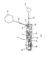
- Fig. 3 is a cross sectional view best showing the configuration of the laser scanner device 5 according to this embodiment of the present invention.
- a scanner casing 51 is beforehand provided with a mounting bearing surface for the reflection mirror 5c in order to enable the reflection mirror 5c to be installed according to the specification required upon manufacture of the laser scanner device 5.
- the other component parts designated by the same symbols as those in Fig. 2 are the same ones as in Fig. 2.
- a laser beam 6 reflected by the polygon mirror 5b mounted on a rotating shaft of the polygon motor 5g arrives at the mounting bearing surface for the reflection mirror 5c through the f ⁇ lenses 5f, 5e.
- the laser beam 6 passes through a dustproof glass 5j installed on the scanner casing 51 at a first opening formed therethrough to become a laser beam 6a, which is focused on a photosensitive drum 7a to form an image thereon.
- the laser beam 6 is reflected by the reflection mirror 5c to pass through a dustproof glass 5k, which is installed on the scanner casing 51 at a second opening formed therethrough, to become a laser beam 6b, which is then focused on a photosensitive drum 7b to form an image thereon.
- the scanner casing 51 has the mounting bearing surface for the reflection mirror 5c, which is molded from a molding resin for instance.
- the laser diode 5a, the polygon motor 5g and the lenses 5f, 5e are arranged at the upstream side of the reflection mirror 5c, so that these components can be used in common regardless of the presence or absence of the reflection mirror 5c.
- the first and second openings are formed through the scanner casing 51 at prescribed locations, respectively, so as to permit the laser beam to pass through these openings to the outside of the apparatus.
- the dustproof glass 5k installed on the casing 51 at the second opening need not be made of glass.
- the dustproof glass 5j installed on the casing 51 at the first opening need not be glass, either.
- these dustproof glasses may be replaced with other appropriate closure members or light blocking members such as, for instance, black plastic plates, etc., as long as the openings can only be closed with the closure members, respectively.
- Fig. 4 shows the laser scanner device 5 when the reflection mirror 5c in Fig. 3 is not installed.
- application of the present invention to a monochromatic copying machine will result in the image forming apparatus of the configuration as shown in Fig. 1.
- Fig. 5 shows the configuration of the laser scanner device 5 when the reflection mirror 5c is installed in Fig. 3.
- Fig. 6 shows, for instance, a color-image forming apparatus using the laser scanner device 5 of Fig. 5.
- the image forming apparatus 1 is provided at its lower portion with a paper feed means 2, and at its upper portion with an image reading device 9.
- Successive sheets of paper sent out one by one from the paper feed means 2 are clampingly conveyed by a plurality of pairs (though only one pair being illustrated) of conveying rollers 11 along a vertical sheet conveying path 8 to arrive at a pair of registration rollers 3.
- image information which has been read in by the image reading device 9, and electronic image information, which has been transmitted through a network or a facsimile line connected to the image forming apparatus 1, are converted from electronic form into optical information.
- the image information thus converted is sent to the laser scanner device 5, which is a means for forming a latent image by irradiating the optical information onto a photosensitive member, and which is fixedly installed on a holding stay 15.
- the laser scanner device 5 an image is formed as a latent image on the photosensitive member in the form of a photosensitive drum 7 by means of a laser beam.
- the pair of registration rollers 3 are rotated to convey the sheets of paper by synchronizing the image writing timing at the leading-edge position of each sheet with the laser scanner device 5, so that the toner image on the photosensitive drum 7 is transferred to each sheet of paper by means of a transfer roller 10, and thereafter the sheets are conveyed upwardly to arrive at a fixing unit 18, which is arranged at an upper portion of the apparatus 1.
- the fixing unit 18 the unfixed toner is fixed onto the sheets of paper under application of pressure and heat, and the sheets are then conveyed to a discharged paper stacker 12.
- a toner supplied by a container such as one of toner cartridges 16 reaches a corresponding one of developing units 13, where it further proceeds to a corresponding developing sleeve 13a while being stirred therein, wherefrom the toner is supplied to the photosensitive drum 7.
- the toner image developed by each developing unit 13 is transferred to an image transfer belt (ITB) 17, by which it is then conveyed to the transfer roller 10 of a paper passing and conveying part where the toner image is transferred to the sheets of paper which have been conveyed there from the paper feed means 2.
- IB image transfer belt
- the laser scanner device 5 can be arranged at an arbitrary location with respect to the photosensitive drum 7 at which an image is formed or focused by the reflection mirror 5c, it is possible to arrange the laser scanner device 5 in a space below the developing units 13 while enabling the laser beam 6b from the laser scanner device 5 to be irradiated onto the photosensitive drum 7.
- the optical path lengths of laser beams from the point of emission of the laser diode to the photosensitive drum 7 in both of the configurations of Fig. 4 and Fig. 5 are made substantially equal to each other regardless of the presence or absence of the reflection mirror 5c.
- a means for expanding the image information in the main scanning direction by means of the polygon motor 5g serves to enable an image to be written into the surface of the photosensitive drum by making the angle of rotation and the pitch of writing irradiation constant by means of the polygon mirror 5b and the f ⁇ lenses 5e, 5f.
- the position at which a laser beam is emitted by the laser diode is controlled by a laser emission control means by detecting the position and timing of the laser beam by the use of a laser beam detection means in the form of the BD sensor 5i.
- the position at which the laser beam is emitted is controlled by deciding a maximum writing width in the main scanning direction through software based on the information on the main scanning and the first writing position obtained beforehand by detecting the position of the laser beam by means of the BD sensor 5i.
- the widths of the lenses and the width of the reflection mirror, which are arranged in the laser beam paths between the laser diode and the reflection mirror mounting bearing surface, are set so as to meet the sizes of several kinds of transfer sheets as well as to accommodate the widest possible sheets.
- a means for mounting the laser scanner device 5 is common and unchanged regardless of the presence or absence of the reflection mirror, and hence the holding stay 15 is arranged in consideration of the arrangement of the photosensitive drum 7 employed in the image forming apparatus of Fig. 6 in such a manner that a laser beam from the laser scanner device 5 can be focused on the photosensitive drum 7.
- the holding stay is also arranged in consideration of the arrangement of the photosensitive drum 7 employed in the image forming apparatus of Fig. 1.
- the position of the photosensitive drum is first decided, and an appropriate angle of the reflection mirror is then selectively decided within the range between the first angle of reflection and the second angle of reflection so as to enable the laser beam to be irradiated onto the photosensitive drum while taking account of the position of the holding stay.
- the laser scanner device in which the direction of a laser beam to be irradiated onto a photosensitive member can be corrected or adjusted into different directions depending upon the presence or absence and the kind of the reflection mirror, it is possible to commonly use tooling, measuring instruments, etc., for ensuring the accuracy of an image formed. As a result, mass production lines can be smoothly changed for limited production of diversified products, thereby making it possible to improve productivity.
- a laser scanner device which has been once used in one image forming apparatus, can be reused in another image forming apparatus of a different construction merely by adding or changing part of the components of the once used laser scanner device. This results in resource savings.
- the present invention it is possible to easily form several kinds of laser beam paths by providing or unproviding a reflection mirror or by changing, if provided, the mounting angle of the reflection mirror in accordance with the specification required of a laser scanner device. Accordingly, it is unnecessary to design parts such as laser scanner casings, etc., of a variety of image forming apparatuses in compliance with the specifications thereof, as a consequence of which the man-hours and costs required to individually design such parts and hence apparatuses can be reduced.
- a laser scanner device which has been once used in one image forming apparatus, can be reused in another image forming apparatus of a different construction merely by adding or removing a reflection mirror to or from the laser scanner device, or by installing a reflection mirror with a different reflection angle on the laser scanner device. This serves to contribute to resource savings as well as improvements in productivity and serviceability.
- the laser scanner includes a light source with a laser diode, a polygon motor with a polygon mirror mounted on a rotating shaft thereof, scanning lenses, a BD detection device, and a scanner casing with the BD detection device being held thereby and received therein.
- the single scanner casing is provided therein with a mounting bearing surface, which serves to permit a plurality of mirror configurations to be housed and arranged therein in accordance with the presence or absence of a reflection mirror, whereby it is possible to selectively form optical paths for irradiating a plurality of laser beams onto a photosensitive drum.
Landscapes
- Mechanical Optical Scanning Systems (AREA)
- Facsimile Scanning Arrangements (AREA)
- Laser Beam Printer (AREA)
- Exposure Or Original Feeding In Electrophotography (AREA)
- Facsimile Heads (AREA)
Abstract
Description
Claims (6)
- A laser optical apparatus comprising:a laser source for emitting a laser beam;scanning means for changing and scanning the laser beam emitted from said laser source; andan optical casing with said laser source and said scanning means accommodated therein, said optical casing having a first opening and a second opening formed for selectively permitting the laser beam scanned by said scanning means to pass therethrough.
- The laser optical apparatus according to claim 1, wherein said first opening serves to permit the laser beam scanned by said scanning means to pass therethrough without changing the direction of the optical path of the laser beam, and said second opening serves to permit the laser beam scanned by said scanning means and reflected by a mirror to pass therethrough.
- The laser optical apparatus according to claim 2, wherein said optical casing has a mirror mounting portion for mounting said mirror which serves to direct the laser beam toward said second opening.
- The laser optical apparatus according to claim 3, wherein said mirror mounting portion serves to mount said mirror thereon in such a manner that said mirror has a variable reflection angle with respect to the laser beam.
- The laser optical apparatus according to claim 1, wherein one of said first and second openings formed for permitting the laser beam to pass therethrough is closed with a light transmission member, and the other opening is closed with a light blocking member.
- The laser optical apparatus according to claim 1, wherein said laser optical apparatus is used in common with different image forming apparatuses with one of said first and second openings being selectively employed in accordance with an actually used one of said image forming apparatuses.
Applications Claiming Priority (2)
| Application Number | Priority Date | Filing Date | Title |
|---|---|---|---|
| JP2002225961A JP2004069818A (en) | 2002-08-02 | 2002-08-02 | Laser scanner device and image forming device |
| JP2002225961 | 2002-08-02 |
Publications (2)
| Publication Number | Publication Date |
|---|---|
| EP1386748A1 true EP1386748A1 (en) | 2004-02-04 |
| EP1386748B1 EP1386748B1 (en) | 2006-06-21 |
Family
ID=30112993
Family Applications (1)
| Application Number | Title | Priority Date | Filing Date |
|---|---|---|---|
| EP03017356A Expired - Lifetime EP1386748B1 (en) | 2002-08-02 | 2003-07-31 | Laser optical apparatus |
Country Status (5)
| Country | Link |
|---|---|
| US (1) | US6965104B2 (en) |
| EP (1) | EP1386748B1 (en) |
| JP (1) | JP2004069818A (en) |
| CN (1) | CN1278194C (en) |
| DE (1) | DE60306272T2 (en) |
Families Citing this family (2)
| Publication number | Priority date | Publication date | Assignee | Title |
|---|---|---|---|---|
| US8259149B2 (en) * | 2007-11-27 | 2012-09-04 | Ricoh Company, Ltd. | Method and apparatus for image forming, and computer program product |
| DE102016107101A1 (en) * | 2016-04-18 | 2017-10-19 | Status Pro Maschinenmesstechnik Gmbh | rotating laser |
Citations (4)
| Publication number | Priority date | Publication date | Assignee | Title |
|---|---|---|---|---|
| US5001499A (en) * | 1988-08-26 | 1991-03-19 | Canon Kabushiki Kaisha | Light scanning apparatus and image forming apparatus utilizing same |
| DE19703691A1 (en) * | 1996-01-31 | 1997-10-23 | Asahi Optical Co Ltd | Scanner apparatus e.g. for laser printer |
| US6194713B1 (en) * | 1998-04-21 | 2001-02-27 | Asahi Kogaku Kogyo Kabushiki Kaisha | Scanning optical device having a rotatable adjustable holder |
| JP2002225961A (en) | 2001-01-31 | 2002-08-14 | Nippon Felt Co Ltd | Device for storing line material for connecting paper making fabric |
Family Cites Families (1)
| Publication number | Priority date | Publication date | Assignee | Title |
|---|---|---|---|---|
| US5844707A (en) * | 1996-01-31 | 1998-12-01 | Asahi Kogaku Kogyo Kabushiki Kaisha | Scanning optical device |
-
2002
- 2002-08-02 JP JP2002225961A patent/JP2004069818A/en active Pending
-
2003
- 2003-07-31 DE DE60306272T patent/DE60306272T2/en not_active Expired - Lifetime
- 2003-07-31 EP EP03017356A patent/EP1386748B1/en not_active Expired - Lifetime
- 2003-08-01 US US10/631,729 patent/US6965104B2/en not_active Expired - Fee Related
- 2003-08-01 CN CNB031496121A patent/CN1278194C/en not_active Expired - Fee Related
Patent Citations (4)
| Publication number | Priority date | Publication date | Assignee | Title |
|---|---|---|---|---|
| US5001499A (en) * | 1988-08-26 | 1991-03-19 | Canon Kabushiki Kaisha | Light scanning apparatus and image forming apparatus utilizing same |
| DE19703691A1 (en) * | 1996-01-31 | 1997-10-23 | Asahi Optical Co Ltd | Scanner apparatus e.g. for laser printer |
| US6194713B1 (en) * | 1998-04-21 | 2001-02-27 | Asahi Kogaku Kogyo Kabushiki Kaisha | Scanning optical device having a rotatable adjustable holder |
| JP2002225961A (en) | 2001-01-31 | 2002-08-14 | Nippon Felt Co Ltd | Device for storing line material for connecting paper making fabric |
Also Published As
| Publication number | Publication date |
|---|---|
| DE60306272T2 (en) | 2007-06-14 |
| CN1278194C (en) | 2006-10-04 |
| US20040065820A1 (en) | 2004-04-08 |
| EP1386748B1 (en) | 2006-06-21 |
| CN1490679A (en) | 2004-04-21 |
| DE60306272D1 (en) | 2006-08-03 |
| US6965104B2 (en) | 2005-11-15 |
| JP2004069818A (en) | 2004-03-04 |
Similar Documents
| Publication | Publication Date | Title |
|---|---|---|
| US8947750B2 (en) | Imaging device array and image forming apparatus | |
| US7990590B2 (en) | Image forming apparatus, image quality control method | |
| US9377609B2 (en) | Imaging element array and image forming apparatus | |
| US8135294B2 (en) | Image forming apparatus for forming image on record medium | |
| US7130089B2 (en) | Original document scanning apparatus | |
| JP7175671B2 (en) | image forming device | |
| EP2423756A1 (en) | Image reading device and image forming incorporating same | |
| EP1386748B1 (en) | Laser optical apparatus | |
| JP5988039B2 (en) | Light source unit, scanning optical device, and image forming apparatus | |
| JP5093458B2 (en) | Photostatic device, image carrier unit, image forming unit, and image forming apparatus | |
| CN104284050B (en) | The housing of image read-out and balladeur train, balladeur train | |
| JP5492829B2 (en) | Image forming apparatus | |
| JP5588953B2 (en) | Image reading apparatus and image forming apparatus having the same | |
| JP5679945B2 (en) | Lens array and reading apparatus, exposure apparatus, and image forming apparatus using the same | |
| JP2004155522A (en) | Image forming device | |
| JP4617731B2 (en) | Image forming apparatus | |
| JP6942519B2 (en) | Image forming device and photoconductor unit | |
| JP7604910B2 (en) | Exposure device, image forming device, light receiving device and reading device | |
| JP2004147078A (en) | Image reading device and image forming device | |
| JP2005077452A (en) | Image forming apparatus and drive control method thereof | |
| JP6575784B2 (en) | Optical scanning device and image forming apparatus including the optical scanning device | |
| JPH10260603A (en) | Fixing device and image forming device | |
| JPH11327246A (en) | Image forming device | |
| JP2016208132A (en) | Automatic document feeder and image forming apparatus including the same | |
| JP2008102380A (en) | Image reading apparatus and image forming apparatus having the same |
Legal Events
| Date | Code | Title | Description |
|---|---|---|---|
| PUAI | Public reference made under article 153(3) epc to a published international application that has entered the european phase |
Free format text: ORIGINAL CODE: 0009012 |
|
| 17P | Request for examination filed |
Effective date: 20030731 |
|
| AK | Designated contracting states |
Kind code of ref document: A1 Designated state(s): AT BE BG CH CY CZ DE DK EE ES FI FR GB GR HU IE IT LI LU MC NL PT RO SE SI SK TR |
|
| AX | Request for extension of the european patent |
Extension state: AL LT LV MK |
|
| 17Q | First examination report despatched |
Effective date: 20040503 |
|
| AKX | Designation fees paid |
Designated state(s): DE FR GB IT |
|
| GRAP | Despatch of communication of intention to grant a patent |
Free format text: ORIGINAL CODE: EPIDOSNIGR1 |
|
| GRAS | Grant fee paid |
Free format text: ORIGINAL CODE: EPIDOSNIGR3 |
|
| GRAA | (expected) grant |
Free format text: ORIGINAL CODE: 0009210 |
|
| AK | Designated contracting states |
Kind code of ref document: B1 Designated state(s): DE FR GB IT |
|
| REG | Reference to a national code |
Ref country code: GB Ref legal event code: FG4D |
|
| REF | Corresponds to: |
Ref document number: 60306272 Country of ref document: DE Date of ref document: 20060803 Kind code of ref document: P |
|
| ET | Fr: translation filed | ||
| PLBE | No opposition filed within time limit |
Free format text: ORIGINAL CODE: 0009261 |
|
| STAA | Information on the status of an ep patent application or granted ep patent |
Free format text: STATUS: NO OPPOSITION FILED WITHIN TIME LIMIT |
|
| 26N | No opposition filed |
Effective date: 20070322 |
|
| REG | Reference to a national code |
Ref country code: FR Ref legal event code: PLFP Year of fee payment: 14 |
|
| PGFP | Annual fee paid to national office [announced via postgrant information from national office to epo] |
Ref country code: IT Payment date: 20160704 Year of fee payment: 14 Ref country code: DE Payment date: 20160731 Year of fee payment: 14 Ref country code: GB Payment date: 20160727 Year of fee payment: 14 |
|
| PGFP | Annual fee paid to national office [announced via postgrant information from national office to epo] |
Ref country code: FR Payment date: 20160726 Year of fee payment: 14 |
|
| REG | Reference to a national code |
Ref country code: DE Ref legal event code: R119 Ref document number: 60306272 Country of ref document: DE |
|
| GBPC | Gb: european patent ceased through non-payment of renewal fee |
Effective date: 20170731 |
|
| REG | Reference to a national code |
Ref country code: FR Ref legal event code: ST Effective date: 20180330 |
|
| PG25 | Lapsed in a contracting state [announced via postgrant information from national office to epo] |
Ref country code: DE Free format text: LAPSE BECAUSE OF NON-PAYMENT OF DUE FEES Effective date: 20180201 Ref country code: GB Free format text: LAPSE BECAUSE OF NON-PAYMENT OF DUE FEES Effective date: 20170731 |
|
| PG25 | Lapsed in a contracting state [announced via postgrant information from national office to epo] |
Ref country code: FR Free format text: LAPSE BECAUSE OF NON-PAYMENT OF DUE FEES Effective date: 20170731 |
|
| PG25 | Lapsed in a contracting state [announced via postgrant information from national office to epo] |
Ref country code: IT Free format text: LAPSE BECAUSE OF NON-PAYMENT OF DUE FEES Effective date: 20170731 |