EP1386735B1 - Dampening water spraying device - Google Patents
Dampening water spraying device Download PDFInfo
- Publication number
- EP1386735B1 EP1386735B1 EP03253736A EP03253736A EP1386735B1 EP 1386735 B1 EP1386735 B1 EP 1386735B1 EP 03253736 A EP03253736 A EP 03253736A EP 03253736 A EP03253736 A EP 03253736A EP 1386735 B1 EP1386735 B1 EP 1386735B1
- Authority
- EP
- European Patent Office
- Prior art keywords
- nozzle
- fixing member
- holder
- spraying device
- dampening water
- Prior art date
- Legal status (The legal status is an assumption and is not a legal conclusion. Google has not performed a legal analysis and makes no representation as to the accuracy of the status listed.)
- Expired - Lifetime
Links
Images





Classifications
-
- B—PERFORMING OPERATIONS; TRANSPORTING
- B41—PRINTING; LINING MACHINES; TYPEWRITERS; STAMPS
- B41F—PRINTING MACHINES OR PRESSES
- B41F7/00—Rotary lithographic machines
- B41F7/20—Details
- B41F7/24—Damping devices
- B41F7/30—Damping devices using spraying elements
-
- B—PERFORMING OPERATIONS; TRANSPORTING
- B05—SPRAYING OR ATOMISING IN GENERAL; APPLYING FLUENT MATERIALS TO SURFACES, IN GENERAL
- B05B—SPRAYING APPARATUS; ATOMISING APPARATUS; NOZZLES
- B05B15/00—Details of spraying plant or spraying apparatus not otherwise provided for; Accessories
- B05B15/60—Arrangements for mounting, supporting or holding spraying apparatus
- B05B15/65—Mounting arrangements for fluid connection of the spraying apparatus or its outlets to flow conduits
-
- B—PERFORMING OPERATIONS; TRANSPORTING
- B05—SPRAYING OR ATOMISING IN GENERAL; APPLYING FLUENT MATERIALS TO SURFACES, IN GENERAL
- B05B—SPRAYING APPARATUS; ATOMISING APPARATUS; NOZZLES
- B05B1/00—Nozzles, spray heads or other outlets, with or without auxiliary devices such as valves, heating means
- B05B1/14—Nozzles, spray heads or other outlets, with or without auxiliary devices such as valves, heating means with multiple outlet openings; with strainers in or outside the outlet opening
- B05B1/20—Perforated pipes or troughs, e.g. spray booms; Outlet elements therefor
- B05B1/202—Perforated pipes or troughs, e.g. spray booms; Outlet elements therefor comprising inserted outlet elements
-
- F—MECHANICAL ENGINEERING; LIGHTING; HEATING; WEAPONS; BLASTING
- F16—ENGINEERING ELEMENTS AND UNITS; GENERAL MEASURES FOR PRODUCING AND MAINTAINING EFFECTIVE FUNCTIONING OF MACHINES OR INSTALLATIONS; THERMAL INSULATION IN GENERAL
- F16B—DEVICES FOR FASTENING OR SECURING CONSTRUCTIONAL ELEMENTS OR MACHINE PARTS TOGETHER, e.g. NAILS, BOLTS, CIRCLIPS, CLAMPS, CLIPS OR WEDGES; JOINTS OR JOINTING
- F16B21/00—Means for preventing relative axial movement of a pin, spigot, shaft or the like and a member surrounding it; Stud-and-socket releasable fastenings
- F16B21/02—Releasable fastening devices locking by rotation
- F16B21/04—Releasable fastening devices locking by rotation with bayonet catch
Definitions
- dampening arrangement for supplying dampening water prepared with various additives onto printing plate surfaces or onto peripheral surfaces of rollers leading to the printing plates, and particularly, printing machines in off-set newspaper presses (hereinafter simply called “newspaper presses”) are often provided with dampening arrangement.
- Dampening water spraying devices to be used in the dampening arrangement mainly include those of a so-called single fluid type wherein pressurized dampening water is pushed out and sprayed.
- pressurized dampening water is supplied into the spraying device, and the water is alternately stopped and flowed by an operation of an electromagnetic opening/closing valve such that the dampening water is intermittently sprayed from a nozzle attached to a tip end side of the electromagnetic opening/closing valve.
- the prior art concerning a nozzle for spraying dampening water to be utilized in the aforementioned spraying device includes that disclosed in Japanese Patent No. 3035371.
- the spraying device described in the Japanese Patent No. 3035371 includes: a nozzle 20f having an orifice 23f; a nozzle holder 30f for supporting the nozzle; a nozzle fixing member 40f in a nut shape for fixing the nozzle to the nozzle holder; and an electromagnetic opening/closing valve 13f for alternately stopping and flowing dampening water; such that the dampening water is appropriately sprayed by the operation of the electromagnetic opening/closing valve 13f.
- the nozzle 20f is to be fixed to the nozzle holder 30f by the nozzle fixing member 40f, and the attachment and detachment of the nozzle 20f to and from the nozzle holder 30f is to be conducted by a tool.
- the nozzle 20f Upon attachment of the nozzle 20f, the nozzle 20f is inserted into the nozzle fixing member 40f, and the nozzle fixing member 40f is threaded by a tool onto a male screw 52f provided at the tip end portion of the nozzle holder 30f, while the nozzle fixing member 40f is also loosened by the tool such as when the spray of the dampening water becomes defective.
- the spraying device of the prior art disclosed in the Japanese Patent No. 3035371 has such a problem to be solved. Namely, the spraying device of the prior art is intended to spray the dampening water atomized to have a uniform particle diameter from the orifice of the nozzle, by adjusting a supplying pressure of the dampening water so as to improve the printing quality.
- the present invention provides a dampening water spraying device for spraying dampening water from a nozzle onto a printing plate surface or onto a peripheral surface of a roller leading to the printing plate, the spraying device comprising:
- the nozzle attachment/detachment moving portion of the nozzle fixing member interacts with the groove of the nozzle holder, to thereby fix the nozzle to the nozzle holder.
- the groove of the nozzle fixing member interacts with the nozzle attachment/detachment moving portion of the nozzle holder, to thereby fix the nozzle to the nozzle holder.
- Both of the dampening water spraying devices recited in claim 1 and claim 2 allow to readily and manually attach/detach the nozzle without using any mounting tools, thereby contributing to mitigating a work burden of a responsible person.
- the dampening water spraying device of claim 1 or 2 it is desirable for the dampening water spraying device of claim 1 or 2, that the nozzle attachment/detachment moving portion is a protruded body, and that the groove to be engaged with the nozzle attachment/detachment moving portion is a helical groove shorter than the circumference of a peripheral portion to be provided with the helical groove.
- the attachment and detachment of the nozzle can be conducted in a one-touch manner.
- the dampening water spraying device of claim 1 or 2 it is desirable for the dampening water spraying device of claim 1 or 2, that the nozzle attachment/detachment moving portion and the groove to be engaged with the nozzle attachment/detachment moving portion are threaded members, respectively.
- Devising the shape of the nozzle fixing member in this way facilitates to detach the nozzle from the nozzle holder.
- the dampening water spraying device of any one of claims 1 through 5 that the nozzle is incorporated in the nozzle fixing member in a manner to be allowed to move relative to the nozzle fixing member, and to be prevented from separating from the nozzle fixing member.
- the nozzle is not inadvertently separated from the nozzle fixing member even when the nozzle fixing member is detached from the nozzle holder.
- said nozzle fixing member comprises a cylindrical member threadingly inserted into the inner peripheral portion of the nozzle fixing member.
- the handhold portion comprises at least one projected portion projected from the outer peripheral portion of the nozzle fixing member.
- the nozzle can be readily attached and detached without requiring any special tools.
- the spraying devices according to the present invention are plurally incorporated into a spraying bar 10 of a dampening arrangement provided in a printing machine P (see FIG. 13) of a newspaper press such as an offset press.
- the spraying bar 10 is provided to oppose to a roller R for supplying dampening water to a plate cylinder C, and the spraying devices 11 are to be mounted on a supporting member 12, typically at 8 points aligned in an axial direction of the plate cylinder C as shown in FIG. 14.
- the spraying device 11 as the first embodiment of the present invention is shown in FIG. 3, FIG. 4 and FIG. 5.
- the spraying device 11a as the second embodiment is shown in FIG. 7. Since the sole difference between the first embodiment and second embodiment resides in that the second embodiment has a cylindrical member 51a forming an outer peripheral surface of a nozzle holder 30a, the second embodiment will be explained by simultaneously describing the same in brackets. Note, reference numerals of constituent parts inherent in the second embodiment will be shown in brackets in the following text.
- the spraying device 11 (11a) is constituted to include:
- the nozzle 20 includes a small diameter portion 21 and a large diameter portion 22, and the small diameter portion 21 is provided with an orifice 23 for spraying dampening water.
- the large diameter portion 22 is provided with cut-out surfaces 24, 24 established by partly removing the large diameter portion so as to provide a width larger than the diameter of the small diameter portion 21, and the large diameter portion 22 includes a lower surface 28 provided with an O-ring 25.
- the end surface 32 is provided with the positioning means 31, 31 for connecting the nozzle 20 and for determining the phase (i.e. the angular position with respect to the axis of the nozzle) thereof.
- the positioning means 31, 31 are protrudedly provided on the end surface 32 in a manner to oppose to each other: at a spacing slightly larger than the width dimension between the cut-out surfaces 24, 24 provided at the large diameter portion 22 of the nozzle 20 (see FIG. 6A) ; and at a height not exceeding the thickness of the large diameter portion 22; thereby making it possible to determine the phase of the nozzle 20 by assembling the cut-out surfaces 24, 24 of the nozzle 20 into a position between the positioning means 31, 31 matchingly thereto, respectively. As shown in FIG. 7, FIG. 8A through FIG.
- the cylindrical member 51a of the second embodiment includes setscrews 56a, 56a, and the cylindrical member is fitted on the nozzle holder 30a and fastened to the neck 33 by the setscrews 56a, 56a so that the cylindrical member is integrally fixed to the nozzle holder 30a.
- the grooves 52, 53, 54 and 52, 53, 54 are substantially symmetrically provided at pertinent depths of the outer peripheral portion of the nozzle holder 30 or cylindrical member 51a, as two continuous helical grooves each having a length shorter than the circumference of the outer peripheral portion in a manner to obtain a desired travel distance such as when each helical groove is traveled by 90 degrees in a right-hand screw direction. Further, each groove 52 has distal ends provided with the grooves 53, 54 having no helical angles over an appropriate range, respectively.
- the vertical grooves 59, 59 act as guiding paths for the nozzle attachment/detachment moving portions 50, 50 upon attaching the nozzle fixing member 40 to the nozzle holder 30 (in the second embodiment, to the cylindrical member 51a), respectively.
- the nozzle fixing member 40 includes: an opening portion 41 opened into an elongated hole shape and opposed to the end surface 32, such that the nozzle 20 can be inserted into the opening portion 41 from the large diameter portion 22; and projected portions 43, 43 projected from an outer peripheral portion 42 so as to act as handhold portions, respectively.
- the opening portion 41 is provided at a central position of that portion of the nozzle fixing member 40 which opposes to the end surface 32 of the nozzle holder 30 (30a) when the nozzle fixing member 40 is attached to the nozzle holder 30 (in the second embodiment, to the cylindrical member 51a).
- the phase relationship among the positioning means 31, 31, the opening portion 41 of nozzle fixing member 40, the nozzle attachment/detachment moving portions 50, 50, and the grooves 52, 53, 54 and 52, 53, 54 is settled such that the major axis of the opening portion 41 becomes perpendicular to the opposing direction between the positioning means 31, 31 when the nozzle attachment/detachment moving portions 50, 50 are placed in the recesses 57, 57, respectively, and such that the cut-out surfaces 24, 24 of the nozzle 20 are inserted between the positioning means 31, 31 to thereby determine the phase at issue when the large diameter portion 22 of the nozzle 20 is inserted into the opening portion 41 in the aforementioned perpendicular state.
- the phase of the nozzle 20 inserted through the opening portion 41 is determined by the positioning means 31, 31 provided at the nozzle holder 30 (30a).
- the nozzle fixing member 40 is to be manually rotated around the nozzle holder 30 (in the second embodiment, around the cylindrical member 51a integral with the nozzle holder 30a) in a direction where the nozzle attachment/detachment moving portions 50, 50 move along the grooves 52, 52, i.e., in the clockwise direction.
- the nozzle fixing member 40 is moved in the axial direction of the nozzle holder 30 (30a), and the edge portions passed through by the minor axis of the opening portion 41 in the elongated hole shape are covered onto the portions of the large diameter portion 22 which are not cut out, so that the large diameter portion 22 is seized by a lower surface 45 of the edge portions passed through by the minor axis to thereby fix the nozzle 20.
- the nozzle attachment/detachment moving portions 50, 50 are movable through the vertical grooves 59, 59, so that the nozzle fixingmember 40 is removable relative to the nozzle holder 30 (in the second embodiment, relative to the cylindrical member 51a integral with the nozzle holder 30a).
- the nozzle attachment/detachment moving portions 50, 50 are provided to establish protruded bodies at the inner peripheral portion of the nozzle fixing member 40, at one sides of engagement adjusting members 55, 55 insertedly provided in the projected portions 43, 43 projected as handhold portions from the outer peripheral portion 42 of the nozzle fixing member 40.
- the nozzle attachment/detachment moving portions 50, 50 are spherical bodies to be pushed out by spring-like elastic bodies (not shown) provided inside the engagement adjustingmembers 55, 55 formed as threaded rod bodies, such that portions of the spherical bodies are pushed out from the threaded rod bodies by appropriate forces to thereby contact the nozzle attachment/detachment moving portions 50 with the associated grooves 52 by appropriate forces, respectively.
- the nozzle attachment/detachment moving portion 50 is pushed back by the bottom surface of the groove 52 when the nozzle attachment/detachment moving portions 50 is midway along the groove 52, while the nozzle attachment/detachment moving portion 50 falls into the recess 57 and recess 58 provided at the distal end portions of the groove 52 when the nozzle attachment/detachment moving portion 50 is at such distal end portions, respectively, thereby assuredly holding the nozzle attachment/detachment moving portion 50 at such positions, respectively.
- the nozzle fixing member 40 is fitted onto the nozzle holder 30 (in the second embodiment, onto the cylindrical member 51a) and then the engagement adjusting members 55, 55 are mounted into the projected portions 43, 43 of the nozzle fixing member 40, respectively, in a manner to be engaged with any of grooves 52, 52 or 53, 53 or 54, 54.
- the spraying device 11b as the third embodiment of the present invention will be now shown in FIG. 9 through FIG. 11.
- the spraying device 11b of the third embodiment is constituted to include: a nozzle 20 for spraying dampening water; a nozzle holder 30b, which is integrally attached to one end side of the electromagnetic opening/closing valve 13, which includes positioning means 31b, 31b for the nozzle 20, and which includes an outer peripheral portion provided with a male screw 52b; a nozzle fixing member 40b including an inner peripheral portion provided with a female screw 44b for fixing the nozzle 20 to the nozzle holder 30b; and a nozzle attachment/detachment moving portion 50b including a cylindrical member 51b having an inner peripheral portion formed with a female screw to be engaged with the male screw 52b of the nozzle holder 30b.
- the nozzle 20 includes a small diameter portion 21 and a large diameter portion 22, and the small diameter portion 21 is provided with an orifice 23 for spraying dampening water.
- the large diameter portion 22 is provided with cut-out surfaces 24, 24 established by partly removing the large diameter portion so as to provide a width larger than the diameter of the small diameter portion 21, and the large diameter portion 22 includes a lower surface 28 provided with an O-ring 25.
- the lower surface 28 of the large diameter portion 22 is closely contacted with a connecting portion of an end surface 32b of the nozzle holder 30b by virtue of elastic deformation of the O-ring 25.
- the nozzle 20 is provided with a separation preventing member 26 for allowing movement of the nozzle and for preventing separation of the nozzle from the nozzle fixing member 40b when the nozzle 20 is incorporated into the nozzle fixing member 40b.
- the separation preventing member 26 is attached to the outer peripheral portion of the large diameter portion 22, such that cut-outs 27, 27 of the separation preventing member 26 are correspondingly matched with the cut-out surfaces 24, 24 of the large diameter portion 22 of the nozzle 20, respectively.
- the separation preventing member 26 is provided with the cut-outs 27, 27 (FIG.
- the separation preventing member 26 never interferes with the positioning means 31b, 31b, when the cut-out surfaces 24, 24 of the nozzle 20 are inserted between the positioning means 31b, 31b provided at the end surface 32b to thereby determine the connecting phase of the nozzle 20.
- the nozzle 20 is not to be separated from the nozzle fixing member 40b in a state where the nozzle 20 is attached into an opening portion 41b of the nozzle fixing member 40b to be described later, even when the nozzle fixing member 40b together with the nozzle 20 is detached from the nozzle holder 30b.
- the nozzle holder 30b is provided with a neck 33b integrated with the electromagnetic opening/closing valve 13, and includes the male screw 52b and the positioning means 31b, 31b, the latter being provided at the end surface 32b so as to determine the connecting phase of the nozzle 20. Since the positioning means 31b, 31b are the same as the positioningmeans 31, 31 in the first embodiment, the explanation of the former shall be omitted.
- the outer peripheral portion of the nozzle holder 30 is formed with the male screw 52b to be engaged with the nozzle attachment/detachment moving portion 50b to be described later, in a manner to engage and interact with the nozzle attachment/detachment moving portion 50b as the female screw formed at the inner peripheral portion of the cylindrical member 51b integral with the nozzle fixing member 40b, thereby allowing to attach and detach the nozzle 20 to and from the nozzle holder 30.
- the nozzle fixing member 40b includes an outer peripheral portion provided with handhold portions for making it possible to to manually rotate the nozzle fixing member 40b.
- the nozzle fixing member 40b includes a circular opening portion 41b into which the nozzle 20 can be inserted, while the female screw 44b provided at the inner peripheral portion of the nozzle fixing member 40b is threaded with a male screw 46b of the cylindrical member 51b to thereby integrally fix the cylindrical member 51b.
- a lower surface 45b of those edge portion of the opening portion 41b which contact with the upper surface of the large diameter portion 22 of the nozzle 20, and an end surface 47b of the threadedly inserted cylindrical member 51b is an appropriate clearance for allowing to accommodate therein the separation preventing member 26 of the nozzle 20.
- the inner peripheral portion of the cylindrical member 51b integral with the nozzle fixing member 40b is provided with the nozzle attachment/detachment moving portion 50b formed with the female screw for obtaining a desired travel distance required to fix the nozzle 20.
- FIG. 10, FIG. 12 show a fourth embodiment of a spraying device according to the present invention.
- the spraying device 11c of the fourth embodiment is constituted to include: a nozzle 20 for spraying dampening water; a nozzle holder 30c, which is integrally attached to one end side of the electromagnetic opening/closing valve 13, which includes positioning means 31c, 31c for the nozzle 20, and which includes an outer peripheral portion provided with a male screw 52c; a nozzle fixing member 40c for fixing the nozzle 20 to the nozzle holder 30c; and a nozzle attachment/detachment moving portion 50c provided at an inner peripheral portion of the nozzle fixing member 40c and formed with a female screw to be engaged with the male screw 52c of the nozzle holder 30c.
- a nozzle 20 for spraying dampening water a nozzle holder 30c, which is integrally attached to one end side of the electromagnetic opening/closing valve 13, which includes positioning means 31c, 31c for the nozzle 20, and which includes an outer peripheral portion provided with
- the nozzle 20 is the same as that in the first embodiment shown in FIG. 6A, FIG. 6B, and the explanation of the former shall be omitted.
- the nozzle holder 30c is provided with a neck 33c integrated with the electromagnetic opening/closing valve 13, and includes an end surface 32c provided with positioning means 31c, 31c for determining the connecting phase of the nozzle 20.
- the positioning means 31c, 31c are the same as the positioning means 31, 31 of the first embodiment and second embodiment, so that the explanation of the former shall be omitted.
- the nozzle holder 30c includes an outer peripheral portion provided with the male screw 52c to be engaged with the nozzle attachment/detachment moving portion 50c to be described later, in a manner to engage and interact with the nozzle attachment/detachment moving portion 50c as the female screw formed at the inner peripheral portion of the nozzle fixing member 40c, thereby making it possible to to attach and detach the nozzle 20 to and from the nozzle holder 30c.
- the nozzle fixing member 40c includes an outer peripheral portion provided with handhold portions for making it possible to to manually rotate the nozzle fixing member 40c.
- the nozzle fixing member 40c includes a circular opening portion 41c into which the nozzle 20 can be inserted, and the nozzle fixing member 40c includes an inner peripheral portion provided with the nozzle attachment/detachment moving portion 50c formed with a female screw for allowing to obtain a desired travel distance required to fix the nozzle 20.
- the first embodiment according to the present invention is the same as the second embodiment except that the nozzle holder 30 is not mounted with the cylindrical member in the first embodiment, the second embodiment will be explained by simultaneously describing the same in brackets.
- the cylindrical member 51a is to be previously and integrally assembled to the nozzle holder 30a, by fitting the cylindrical member 51a onto the nozzle holder 30a and by fastening the cylindrical member 51a to the neck 33 by the setscrews 56a, 56a.
- the nozzle attachment/detachment moving portions 50, 50 protruded from the inner peripheral portion of the nozzle fixing member 40 to thereby form the protruded bodies are pushed into the axial direction matchedly with the vertical grooves 59, 59 provided in the axial direction of the nozzle holder 30 (in the second embodiment, of the cylindrical member 51a integral with the nozzle holder 30a) .
- the entrances of the vertical grooves 59, 59 are dug deeply, thereby making it possible to to readily insert the nozzle fixing member 40.
- the nozzle attachment/detachment moving portions 50, 50 are pushed in the axial direction, the vertical grooves 59, 59 become shallower and finally reach a constant depth.
- the nozzle attachment/detachment moving portions 50, 50 are outwardly pushed back against the elastic bodies of the engagement adjusting members 55, 55 constituting the threaded rod bodies provided in the nozzle fixing member 40, and instantly fall into the recesses 57, 57 upon reaching the terminating ends of the vertical grooves 59, 59, respectively.
- This completes the fitting of the nozzle fixing member 40, and the positions of the recesses 57, 57 define the starting position of the nozzle fixing member 40 for starting the fixing of the nozzle 20.
- the nozzle 20 can be inserted between the positioning means 31, 31 projectedly provided at the end surface 32, by inserting the large diameter portion 22 of the nozzle 20 through the opening portion 41.
- the nozzle 20 In attaching the nozzle 20 to the nozzle holder 30 (30a), the nozzle 20 is inserted through the opening portion 41, and the phase of the nozzle 20 is determined by assembling the cut-out surfaces 24, 24 of the nozzle 20 into a position between the positioning means 31, 31 matchingly thereto, respectively.
- the nozzle fixing member 40 is manually rotated clockwise. This causes the nozzle attachment/detachment moving portions 50, 50 to move from the grooves 53, 53 without helical angles, through helical grooves 52, 52, to the grooves 54, 54 without helical angles, so that the nozzle fixing member 40 moves axially while rotating.
- the nozzle attachment/detachment moving portions 50, 50 pass along the helical grooves 52, 52 and reach terminating ends of the grooves 54, 54, and then fall into the recesses 58, 58, respectively.
- the upper surface side of the large diameter portion 22 of the nozzle 20 comes to be urged by the lower surface 45 of the edge portions passed through by the minor axis of the opening portion 41 of the nozzle fixing member 40, and the nozzle attachment/detachment moving portions 50, 50 fall into the recesses 58, 58 upon reaching the terminating ends.
- the positions of the recesses 58, 58 define the ending position of the nozzle fixing member 40, i.e., the attachment completing position of the nozzle 20.
- the nozzle 20 is completely closely contacted with and fixed to the end surface 32 of the nozzle holder 30 (30a), by virtue of the elastic deformation of the O-ring 25 provided at the lower surface 28 of the large diameter portion 22.
- This first embodiment (second embodiment) is provided with the grooves 52, 53, 54 and 52, 53, 54 for allowing to obtain a desired travel distance by a turn of 90 degrees around the axis, thereby making it possible to to swiftly fix the nozzle 20 in a so-called one-touch manner.
- the nozzle fixingmember 40 In detaching the nozzle 20 from the nozzle holder 30 (30a), the nozzle fixingmember 40 is rotated in the opposite direction, i.e., from the ending position toward the starting position to thereby release the seizure of the large diameter portion 22 of the nozzle 20, and the nozzle 20 can be then readily detached from the nozzle holder 30 (30a) by picking up the small diameter portion 21 of the nozzle 20 while placing the nozzle fixing member 40 at the starting position. Further, upon cleaning, the nozzle fixing member 40 is drawn out along the vertical grooves 59, 59, thereby making it possible to to detach the nozzle fixing member 40.
- the nozzle 20 provided with the separation preventing member 26 is incorporated into the nozzle fixing member 40b such that the movement of the nozzle 20 is allowed but the separation thereof is prevented by virtue of the cylindrical member 51b, and the nozzle 20 is rotatable relative to the opening portion 41b.
- the nozzle fixing member 40b is moved in the axial direction by the nozzle attachment/detachment moving portion 50b engaged with the male screw 52b of the nozzle holder 30b, so that the upper surface side of the large diameter portion 22 of the nozzle 20 comes to be pushed by the lower surface 45b of the edge portions of the opening portion 41b of the nozzle fixing member 40b, thereby obtaining a desired travel distance of the nozzle fixing member 40b such as by an approximately 1.5 turns, to thereby fix the nozzle 20.
- the cylindrical member 51b is detached from the nozzle fixing member 40b so as to remove the used nozzle and to insert a new nozzle provided with a separation preventing member 26 into the opening portion 41b, and then the cylindrical member 51b is again threaded into the nozzle fixing member 40b.
- the phase of the nozzle 20 is previously determined by assembling the cut-out surfaces 24, 24 of the nozzle 20 into a position between the positioning means 31, 31 of the nozzle holder 30c matchingly thereto, respectively. Then, the inner peripheral portion of the nozzle fixing member 40c is fitted onto the nozzle holder 30c such that the nozzle 20 is inserted into the opening portion 41c. Next, the nozzle fixing member 40c is manually rotated clockwise until the same stops.
- the nozzle fixing member 40c is moved in the axial direction by the nozzle attachment/detachment moving portion 50c engaged with the male screw 52c of the nozzle holder 30c, so that the upper surface side of the large diameter portion 22 of the nozzle 20 comes to be pushed by the lower surface 45c of the edge portions of the opening portion 41c of the nozzle fixing member 40c, thereby obtaining a desired travel distance of the nozzle fixing member 40c such as by an approximately 1.5 turns, to thereby fix the nozzle 20.
- the nozzle fixing member In detaching the nozzle 20, the nozzle fixing member is rotated in the opposite direction to thereby release the engagement of the nozzle attachment/detachment moving portion 50c with the male screw 52c of the nozzle holder 30c, thereby making it possible to to detach the nozzle fixing member 40c. attached with the nozzle 20 from the nozzle holder 30c. Thereafter, the nozzle 20 left on the nozzle holder 30c is removed.
- the outer peripheral portion of the cylindrical member 51a shown in the second embodiment and the outer peripheral portion of the nozzle holder 30 shown in the first embodiment are provided with the nozzle attachment/detachment moving portions 50, respectively, and that the inner peripheral portions of the associated nozzle fixing members 40 are provided with the corresponding grooves, in a manner opposite to: the relationship of the nozzle attachment/detachment moving portions 50 constituting the protruded bodies from the inner peripheral portion of the nozzle fixing member 40, relative to the grooves 52, 53, 54 and recesses 57, 58 at the outer peripheral portion of the cylindrical member 51a; and the relationship of the nozzle attachment/detachment moving portions 50 constituting the protruded bodies from the inner peripheral portion of the nozzle fixing member 40, relative to the grooves 52, 53, 54 and the recesses 57, 58 at the outer peripheral portion of the nozzle holder 30.
Landscapes
- Engineering & Computer Science (AREA)
- Mechanical Engineering (AREA)
- Rotary Presses (AREA)
- Nozzles (AREA)
Description
- The present invention relates to a dampening arrangement in an offset press, and particularly to a dampening water spraying device provided in such an arrangement and including a removable nozzle.
- Generally, offset presses are provided with dampening arrangement for supplying dampening water prepared with various additives onto printing plate surfaces or onto peripheral surfaces of rollers leading to the printing plates, and particularly, printing machines in off-set newspaper presses (hereinafter simply called "newspaper presses") are often provided with dampening arrangement. Dampening water spraying devices (hereinafter simply called "spraying devices") to be used in the dampening arrangement mainly include those of a so-called single fluid type wherein pressurized dampening water is pushed out and sprayed. In such a spraying device, pressurized dampening water is supplied into the spraying device, and the water is alternately stopped and flowed by an operation of an electromagnetic opening/closing valve such that the dampening water is intermittently sprayed from a nozzle attached to a tip end side of the electromagnetic opening/closing valve.
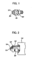
- The prior art concerning a nozzle for spraying dampening water to be utilized in the aforementioned spraying device includes that disclosed in Japanese Patent No. 3035371. As shown in FIG. 1 and FIG. 2, the spraying device described in the Japanese Patent No. 3035371 includes: a
nozzle 20f having anorifice 23f; anozzle holder 30f for supporting the nozzle; anozzle fixing member 40f in a nut shape for fixing the nozzle to the nozzle holder; and an electromagnetic opening/closing valve 13f for alternately stopping and flowing dampening water; such that the dampening water is appropriately sprayed by the operation of the electromagnetic opening/closing valve 13f. Thenozzle 20f is to be fixed to thenozzle holder 30f by thenozzle fixing member 40f, and the attachment and detachment of thenozzle 20f to and from thenozzle holder 30f is to be conducted by a tool. Upon attachment of thenozzle 20f, thenozzle 20f is inserted into thenozzle fixing member 40f, and thenozzle fixing member 40f is threaded by a tool onto amale screw 52f provided at the tip end portion of thenozzle holder 30f, while thenozzle fixing member 40f is also loosened by the tool such as when the spray of the dampening water becomes defective. - The spraying device of the prior art disclosed in the Japanese Patent No. 3035371 has such a problem to be solved. Namely, the spraying device of the prior art is intended to spray the dampening water atomized to have a uniform particle diameter from the orifice of the nozzle, by adjusting a supplying pressure of the dampening water so as to improve the printing quality. However, it is extremely difficult to spray the dampening water of a uniform particle diameter from the orifice of the nozzle over a long time, and the orifice is narrowed as the same is used overtime, because the additives contained in the dampening water are deposited and accumulated to a portion around the orifice. It is also inevitable that the orifice is suddenly clogged with foreign matters during long-term usage, thereby changing a spraying state. If this changed state is left alone, the dampening water is not properly sprayed, thereby causing such a serious defect including not only a deteriorated printing quality but also a contaminatedly printed paper face due to lack of the dampeningwater. As such, it i s necessary for a responsible person to replace the nozzle before such a situation, but the working efficiency upon nozzle replacement has been extremely low because attachment and detachment of the nozzle is to be conducted by the tool.
- It is also typical in newspaper presses to provide eight pieces of nozzles per one printing cylinder capable of printing a sheet of paper having a 4-page width. However, recent newspapers have been remarkably developed into an increased number of pages and into colorization, and one example of printing by a set of newspaper presses includes a situation for printing a newspaper having 48 pages inclusive of 24 pages to be printed in 4 colors, thereby requiring 48 pieces of nozzles for monochrome printing of 24 pages and requiring 192 pieces of nozzles for color printing of 24 pages, thereby resulting in 240 pieces of nozzles to be used. Usually, newspaper publishers often possess a plurality of sets of newspaper presses, and such an increased number of nozzles far exceeding the aforementioned 240 pieces are to be subjected to maintenance, such that the nozzle maintenance becomes an extremely heavy burden to a responsible person in a position for managing the printing quality.
- It is therefore an object of the present invention to sweepingly solve the problems accompanying the prior art to thereby facilitate the maintenance of nozzles thereby improving working efficiency, by providing a dampening water spraying device capable of rapidly and readily replacing nozzles, in a manner: to fix a nozzle to a nozzle holder by manually rotating a nozzle fixing member in one direction relative to the nozzle holder; and to detach the nozzle from the nozzle holder by manually rotating the nozzle fixing member in the other direction relative to the nozzle holder.
- To solve the above problem, the present invention provides a dampening water spraying device for spraying dampening water from a nozzle onto a printing plate surface or onto a peripheral surface of a roller leading to the printing plate, the spraying device comprising:
- a nozzle (20) for spraying dampening water;
- a nozzle holder (30) including an end surface (32) connectable to said nozzle (20);
- a nozzle fixing member (40) including an opening portion (41) adapted to expose at least a spout of said nozzle (20), said nozzle fixing member (40) being adapted to be fastened to said nozzle holder (30) while clamping said nozzle (20) between said nozzle fixing member (40) and said nozzle holder (30);
- said nozzle fixing member (40) including an outer peripheral portion (42) provided with a handhold portion for enabling to manually rotate said nozzle fixing member (40); and
- said nozzle fixing member (40) being capable of fixing said nozzle (20) to said nozzle holder (30) by manually rotating said nozzle fixing member (40) in one direction relative to said nozzle holder (30), and being capable of detaching said nozzle (20) from said nozzle holder (30) by manually rotating said nozzle fixing member (40) in the other direction relative to said nozzle holder (30);
- characterised by:
- the nozzle holder (30) further including an outer peripheral portion provided with at least one groove (52; 53; 54);
- the nozzle fixing member (40) further including an inner peripheral portion provided with a nozzle attachment/detachment moving portion (50) opposed to and engageable with said groove (52; 53; 54); and
- the spraying device further comprising positioning means (31) protudedly provided on the nozzle holder (30) to fix the angular position of said nozzle (20) about its axis relative to said nozzle holder (30).
- In claim 2, the present invention further provides a dampening water spraying device for spraying dampening water from a nozzle onto a printing plate surface or onto a peripheral surface of a roller leading to the printing plate, the spraying device comprising:
- a nozzle (20) for spraying dampening water;
- a nozzle holder (30) including an end surface (32) connectable to said nozzle (20), and an outer peripheral portion having at least one nozzle attachment/detachment moving portion (50);
- a nozzle fixing member (40) including an opening portion (41) adapted to expose at least a spout of said nozzle (20), and an inner peripheral portion provided with a groove (52; 53; 54) opposed to and engageable with said nozzle attachment/detachment moving portion (50), said nozzle fixing member (40) being adapted to be fastened to said nozzle holder (30) while clamping said nozzle (20) between said nozzle fixing member (40) and said nozzle holder (30);
- said nozzle fixing member (40) including an outer peripheral portion (42) provided with a handhold portion for enabling to manually rotate said nozzle fixing member (40); and
- said nozzle fixing member (40) being capable of fixing said nozzle (20) to said nozzle holder (30) by manually rotating said nozzle fixing member (40) in one direction relative to said nozzle holder (30), and being capable of detaching said nozzle (20) from said nozzle holder (30) by manually rotating said nozzle fixing member (40) in the other direction relative to said nozzle holder (30);
- characterised by:
- the spraying device further comprising positioning means (31) protudedly provided on the nozzle holder (30) to fix the angular position of said nozzle (20) about its axis relative to said nozzle holder (30).
- In the dampening water spraying device recited in claim 1, the nozzle attachment/detachment moving portion of the nozzle fixing member interacts with the groove of the nozzle holder, to thereby fix the nozzle to the nozzle holder. In the dampening water spraying device recited in claim 2, the groove of the nozzle fixing member interacts with the nozzle attachment/detachment moving portion of the nozzle holder, to thereby fix the nozzle to the nozzle holder.
- Both of the dampening water spraying devices recited in claim 1 and claim 2 allow to readily and manually attach/detach the nozzle without using any mounting tools, thereby contributing to mitigating a work burden of a responsible person.
- Further, since the maintenance of nozzles are facilitated by virtue of the mitigated burden of a replacing work, it becomes possible to properly manage and stabilize the spraying state of dampening water, thereby making it possible to maintain and improve a printing quality.
- Preferably, as recited in claim 3, it is desirable for the dampening water spraying device of claim 1 or 2, that the nozzle attachment/detachment moving portion is a protruded body, and that the groove to be engaged with the nozzle attachment/detachment moving portion is a helical groove shorter than the circumference of a peripheral portion to be provided with the helical groove.
- Since the nozzle attachment/detachment moving portion is to be engaged with the groove by slightly rotating the nozzle attachment/detachment moving portion, the attachment and detachment of the nozzle can be conducted in a one-touch manner.
- Preferably, as recited in claim 4, it is desirable for the dampening water spraying device of claim 1 or 2, that the nozzle attachment/detachment moving portion and the groove to be engaged with the nozzle attachment/detachment moving portion are threaded members, respectively.
- This makes it possible to similarly fix the nozzle fixing member to the nozzle holder, even when the nozzle attachment/detachment moving portion is not a protruded body but a threaded member.
- More preferably, as recited in claim 5, it is desirable for the dampening water spraying device of any one of claims 1 to 4, wherein said opening portion of said nozzle fixing member has an elongate shape formed to enable said nozzle to pass through said opening portion when said opening portion and said nozzle are placed in a predetermined angular relationship.
- Devising the shape of the nozzle fixing member in this way facilitates to detach the nozzle from the nozzle holder.
- Further preferably, as recited in claim 6, it is desirable for the dampening water spraying device of any one of claims 1 through 5, that the nozzle is incorporated in the nozzle fixing member in a manner to be allowed to move relative to the nozzle fixing member, and to be prevented from separating from the nozzle fixing member.
- Thus, the nozzle is not inadvertently separated from the nozzle fixing member even when the nozzle fixing member is detached from the nozzle holder.
- Further preferably, as recited in claim 7, it is desirable for the dampening water spraying device of any one of claims 1 to 6, wherein said nozzle holder comprises a cylindrical member fitted on the outer peripheral portion of the nozzle holder.
- Preferably, as recited in claim 8, it is desirable for the dampening water spraying device of any one of claims 1 to 6, wherein said nozzle fixing member comprises a cylindrical member threadingly inserted into the inner peripheral portion of the nozzle fixing member.
- By adopting such a cylindrical member, it becomes possible to mitigate a work burden of a responsible person even in the spraying device of the prior art having a screw portion on a nozzle holder, and to facilitate the maintenance of the nozzle.
- More preferably, as recited in Claim 9, it is desirable for the dampening water spraying device of anyone of claims 1 through 8, that the handhold portion comprises at least one projected portion projected from the outer peripheral portion of the nozzle fixing member.
- Since the handholdportion comprises the projected portion, the nozzle can be readily attached and detached without requiring any special tools.
- The foregoing and other features of the present invention will become apparent to those skilled in the art to which the present invention relates from reading the following description with reference to the accompanying drawings, in which:
- FIG. 1 is a partial perspective view of a spraying device of the prior art;
- FIG. 2 is a partial cross-sectional view of the spraying device of FIG. 1;
- FIG. 3 is a partial cross-sectional view of a dampening water spraying device according to a first embodiment of the present invention;
- FIG. 4 is a partial plan view of FIG. 3 and FIG. 7;
- FIG. 5 is a partial perspective view of FIG. 3;
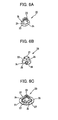
- FIG. 6A is a perspective view of a nozzle viewed from an orifice side;
- FIG. 6B is a perspective view of a large diameter portion of the nozzle viewed from a bottom surface side;
- FIG. 6C is a perspective view of a separation preventing member provided at the large diameter portion of the nozzle in FIG. 6A;
- FIG. is a partial cross-sectional view of a dampening water spraying device according to a second embodiment of the present invention;
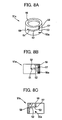
- FIG. 8A is a perspective view of a cylindrical member in FIG. 7;
- FIG. 8B is a partial cross-sectional viewof the cylindrical member of FIG. 8A while showing a vertical groove of the cylindrical member at a right side surface of the latter;
- FIG. 8C is a partial cross-sectional view of the cylindrical member of FIG. 8A while showing the vertical groove of the cylindrical member at a frond side of the latter;
- FIG. 9 is a partial cross-sectional view of a dampening water spraying device according to a third embodiment of the present invention;
- FIG. 10 is a partial plan view of FIG. 9 and FIG. 12;
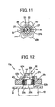
- FIG. 11 is a partial plan view showing a relationship between the nozzle provided with a separation preventing member of Fig.9 and positioning means;
- FIG. 12 is a partial cross-sectional view of a dampening water spraying device according to a fourth embodiment of the present invention;
- FIG. 13 is a front view of a printing machine showing a layout view of a spraying bar provided with the dampening water spraying device according to the present invention; and
- FIG. 14 is a perspective view of the spraying bar in FIG. 13.
- There will be explained hereinafter embodiments according to the present invention, with reference to the drawings.
- The spraying devices according to the present invention are plurally incorporated into a spraying
bar 10 of a dampening arrangement provided in a printing machine P (see FIG. 13) of a newspaper press such as an offset press. The sprayingbar 10 is provided to oppose to a roller R for supplying dampening water to a plate cylinder C, and thespraying devices 11 are to be mounted on a supportingmember 12, typically at 8 points aligned in an axial direction of the plate cylinder C as shown in FIG. 14. - There will be explained hereinafter embodiments of the spraying device 11 (11a, 11b, 11c) according to the present invention.
- The spraying
device 11 as the first embodiment of the present invention is shown in FIG. 3, FIG. 4 and FIG. 5. Thespraying device 11a as the second embodiment is shown in FIG. 7. Since the sole difference between the first embodiment and second embodiment resides in that the second embodiment has acylindrical member 51a forming an outer peripheral surface of anozzle holder 30a, the second embodiment will be explained by simultaneously describing the same in brackets. Note, reference numerals of constituent parts inherent in the second embodiment will be shown in brackets in the following text. - The spraying device 11 (11a) is constituted to include:
- a
nozzle 20 for spraying dampening water; a nozzle holder 30 (30a) integrally attached to one end side of an electromagnetic opening/closingvalve 13 and including positioning means 31, 31 for thenozzle 20; anozzle fixing member 40 for fixing thenozzle 20 to the nozzle holder 30 (30a); and nozzle attachment/detachment moving portions 50 protruded from an inner peripheral portion of thenozzle fixing member 40 in a manner to be opposed to and engaged with two sets ofhelical grooves cylindrical member 51a). There will be explained hereinafter the constitutions of the respective portions. - As shown in FIG. 6A, FIG. 6B, the
nozzle 20 includes asmall diameter portion 21 and alarge diameter portion 22, and thesmall diameter portion 21 is provided with anorifice 23 for spraying dampening water. Thelarge diameter portion 22 is provided with cut-outsurfaces small diameter portion 21, and thelarge diameter portion 22 includes alower surface 28 provided with an O-ring 25. When thenozzle 20 is attached to the nozzle holder 30 (30a) (see FIG. 3, FIG. 7), thelower surface 28 of thelarge diameter portion 22 is closely contacted with a connecting portion of anend surface 32 of thenozzle holder 30 by virtue of elastic deformation of the O-ring 25. - As shown in FIG. 3 and FIG. 7, the nozzle holder 30 (30a) includes a
neck 33 provided integrally with the electromagnetic opening/closingvalve 13. In the second embodiment, the nozzle holder is fitted with thecylindrical member 51a on the outer peripheral portion of the nozzle holder. - The
end surface 32 is provided with the positioning means 31, 31 for connecting thenozzle 20 and for determining the phase (i.e. the angular position with respect to the axis of the nozzle) thereof. The positioning means 31, 31 are protrudedly provided on theend surface 32 in a manner to oppose to each other: at a spacing slightly larger than the width dimension between the cut-outsurfaces large diameter portion 22 of the nozzle 20 (see FIG. 6A) ; and at a height not exceeding the thickness of thelarge diameter portion 22; thereby making it possible to determine the phase of thenozzle 20 by assembling the cut-outsurfaces nozzle 20 into a position between the positioning means 31, 31 matchingly thereto, respectively. As shown in FIG. 7, FIG. 8A through FIG. 8C, thecylindrical member 51a of the second embodiment includessetscrews nozzle holder 30a and fastened to theneck 33 by thesetscrews nozzle holder 30a. - Provided at the outer peripheral portion of the nozzle holder 30 (in case of the second embodiment, at the outer peripheral portion of the
cylindrical member 51a) are thegrooves detachment moving portions detachment moving portions 50, thereby making it possible to attach and detach thenozzle 20 to and from the nozzle holder 30 (30a). - The
grooves nozzle holder 30 orcylindrical member 51a, as two continuous helical grooves each having a length shorter than the circumference of the outer peripheral portion in a manner to obtain a desired travel distance such as when each helical groove is traveled by 90 degrees in a right-hand screw direction. Further, eachgroove 52 has distal ends provided with thegrooves grooves recesses grooves recess 57 andrecess 58 are interconnected by thegroove 52 having thegrooves recesses vertical grooves 59 in the direction separated from therecesses 57 are formed to become continuously deeper. Thevertical grooves detachment moving portions nozzle fixing member 40 to the nozzle holder 30 (in the second embodiment, to thecylindrical member 51a), respectively. - The
nozzle fixing member 40 includes: an openingportion 41 opened into an elongated hole shape and opposed to theend surface 32, such that thenozzle 20 can be inserted into the openingportion 41 from thelarge diameter portion 22; and projectedportions peripheral portion 42 so as to act as handhold portions, respectively. The openingportion 41 is provided at a central position of that portion of thenozzle fixing member 40 which opposes to theend surface 32 of the nozzle holder 30 (30a) when thenozzle fixing member 40 is attached to the nozzle holder 30 (in the second embodiment, to thecylindrical member 51a). The phase relationship among the positioning means 31, 31, the openingportion 41 ofnozzle fixing member 40, the nozzle attachment/detachment moving portions grooves portion 41 becomes perpendicular to the opposing direction between the positioning means 31, 31 when the nozzle attachment/detachment moving portions recesses surfaces nozzle 20 are inserted between the positioning means 31, 31 to thereby determine the phase at issue when thelarge diameter portion 22 of thenozzle 20 is inserted into the openingportion 41 in the aforementioned perpendicular state. Thus, the phase of thenozzle 20 inserted through the openingportion 41 is determined by the positioning means 31, 31 provided at the nozzle holder 30 (30a). After inserting thenozzle 20 into the openingportion 41, thenozzle fixing member 40 is to be manually rotated around the nozzle holder 30 (in the second embodiment, around thecylindrical member 51a integral with thenozzle holder 30a) in a direction where the nozzle attachment/detachment moving portions grooves nozzle fixing member 40 is moved in the axial direction of the nozzle holder 30 (30a), and the edge portions passed through by the minor axis of the openingportion 41 in the elongated hole shape are covered onto the portions of thelarge diameter portion 22 which are not cut out, so that thelarge diameter portion 22 is seized by alower surface 45 of the edge portions passed through by the minor axis to thereby fix thenozzle 20. To release thenozzle 20, there is conducted the reverse operation. Further, the nozzle attachment/detachment moving portions vertical grooves nozzle fixingmember 40 is removable relative to the nozzle holder 30 (in the second embodiment, relative to thecylindrical member 51a integral with thenozzle holder 30a). - As shown in FIG. 3, the nozzle attachment/
detachment moving portions nozzle fixing member 40, at one sides ofengagement adjusting members portions peripheral portion 42 of thenozzle fixing member 40. In detail, the nozzle attachment/detachment moving portions engagement adjustingmembers detachment moving portions 50 with the associatedgrooves 52 by appropriate forces, respectively. The nozzle attachment/detachment moving portion 50 is pushed back by the bottom surface of thegroove 52 when the nozzle attachment/detachment moving portions 50 is midway along thegroove 52, while the nozzle attachment/detachment moving portion 50 falls into therecess 57 andrecess 58 provided at the distal end portions of thegroove 52 when the nozzle attachment/detachment moving portion 50 is at such distal end portions, respectively, thereby assuredly holding the nozzle attachment/detachment moving portion 50 at such positions, respectively. Note, it is possible to attach thenozzle fixing member 40 to the nozzle holder 30 (30a) even without providing thevertical grooves nozzle fixing member 40 is fitted onto the nozzle holder 30 (in the second embodiment, onto thecylindrical member 51a) and then theengagement adjusting members portions nozzle fixing member 40, respectively, in a manner to be engaged with any ofgrooves - The spraying device 11b as the third embodiment of the present invention will be now shown in FIG. 9 through FIG. 11. The spraying device 11b of the third embodiment is constituted to include: a
nozzle 20 for spraying dampening water; anozzle holder 30b, which is integrally attached to one end side of the electromagnetic opening/closingvalve 13, which includes positioning means 31b, 31b for thenozzle 20, and which includes an outer peripheral portion provided with amale screw 52b; anozzle fixing member 40b including an inner peripheral portion provided with a female screw 44b for fixing thenozzle 20 to thenozzle holder 30b; and a nozzle attachment/detachment moving portion 50b including acylindrical member 51b having an inner peripheral portion formed with a female screw to be engaged with themale screw 52b of thenozzle holder 30b. There will be explained hereinafter the constitutions of the respective portions. - As shown in FIG. 6B, FIG. 6C, the
nozzle 20 includes asmall diameter portion 21 and alarge diameter portion 22, and thesmall diameter portion 21 is provided with anorifice 23 for spraying dampening water. Thelarge diameter portion 22 is provided with cut-outsurfaces small diameter portion 21, and thelarge diameter portion 22 includes alower surface 28 provided with an O-ring 25. When thenozzle 20 is attached to thenozzle holder 30b (FIG. 9), thelower surface 28 of thelarge diameter portion 22 is closely contacted with a connecting portion of anend surface 32b of thenozzle holder 30b by virtue of elastic deformation of the O-ring 25. Thenozzle 20 is provided with aseparation preventing member 26 for allowing movement of the nozzle and for preventing separation of the nozzle from thenozzle fixing member 40b when thenozzle 20 is incorporated into thenozzle fixing member 40b. As shown in FIG. 6C, theseparation preventing member 26 is attached to the outer peripheral portion of thelarge diameter portion 22, such that cut-outs separation preventing member 26 are correspondingly matched with the cut-outsurfaces large diameter portion 22 of thenozzle 20, respectively. As shown in FIG. 11, theseparation preventing member 26 is provided with the cut-outs 27, 27 (FIG. 6C) such that theseparation preventing member 26 never interferes with the positioning means 31b, 31b, when the cut-outsurfaces nozzle 20 are inserted between the positioning means 31b, 31b provided at theend surface 32b to thereby determine the connecting phase of thenozzle 20. As further shown in FIG. 9, thenozzle 20 is not to be separated from thenozzle fixing member 40b in a state where thenozzle 20 is attached into anopening portion 41b of thenozzle fixing member 40b to be described later, even when thenozzle fixing member 40b together with thenozzle 20 is detached from thenozzle holder 30b. - As shown in FIG. 9, the
nozzle holder 30b is provided with aneck 33b integrated with the electromagnetic opening/closingvalve 13, and includes themale screw 52b and the positioning means 31b, 31b, the latter being provided at theend surface 32b so as to determine the connecting phase of thenozzle 20. Since the positioning means 31b, 31b are the same as thepositioningmeans nozzle holder 30 is formed with themale screw 52b to be engaged with the nozzle attachment/detachment moving portion 50b to be described later, in a manner to engage and interact with the nozzle attachment/detachment moving portion 50b as the female screw formed at the inner peripheral portion of thecylindrical member 51b integral with thenozzle fixing member 40b, thereby allowing to attach and detach thenozzle 20 to and from thenozzle holder 30. - The
nozzle fixing member 40b includes an outer peripheral portion provided with handhold portions for making it possible to to manually rotate thenozzle fixing member 40b. As shown in FIG. 9, FIG. 10, at the central portion of that portion of thenozzle fixing member 40b which opposes to theend surface 32b of thenozzle holder 30b when thenozzle fixing member 40b is attached to thenozzle holder 30b, thenozzle fixing member 40b includes acircular opening portion 41b into which thenozzle 20 can be inserted, while the female screw 44b provided at the inner peripheral portion of thenozzle fixing member 40b is threaded with amale screw 46b of thecylindrical member 51b to thereby integrally fix thecylindrical member 51b. Provided between, alower surface 45b of those edge portion of theopening portion 41b which contact with the upper surface of thelarge diameter portion 22 of thenozzle 20, and anend surface 47b of the threadedly insertedcylindrical member 51b, is an appropriate clearance for allowing to accommodate therein theseparation preventing member 26 of thenozzle 20. The inner peripheral portion of thecylindrical member 51b integral with thenozzle fixing member 40b is provided with the nozzle attachment/detachment moving portion 50b formed with the female screw for obtaining a desired travel distance required to fix thenozzle 20. Thenozzle 20, which is inserted into theopening portion 41b of thenozzle fixing member 40b and the phase of which nozzle is determined relative to thenozzle holder 30b, is fixed to thenozzle holder 30b by manually rotating thenozzle fixing member 40b clockwise so that thelower surface 45b at the edge portion of theopening portion 41b seizes the upper surface of thelarge diameter portion 22 of thenozzle 20. - Next, FIG. 10, FIG. 12 show a fourth embodiment of a spraying device according to the present invention. The
spraying device 11c of the fourth embodiment is constituted to include: anozzle 20 for spraying dampening water; anozzle holder 30c, which is integrally attached to one end side of the electromagnetic opening/closingvalve 13, which includes positioning means 31c, 31c for thenozzle 20, and which includes an outer peripheral portion provided with amale screw 52c; anozzle fixing member 40c for fixing thenozzle 20 to thenozzle holder 30c; and a nozzle attachment/detachment moving portion 50c provided at an inner peripheral portion of thenozzle fixing member 40c and formed with a female screw to be engaged with themale screw 52c of thenozzle holder 30c. There will be explainedhereinafter the constitutions of the respective portions. - The
nozzle 20 is the same as that in the first embodiment shown in FIG. 6A, FIG. 6B, and the explanation of the former shall be omitted. - As shown in FIG. 12, the
nozzle holder 30c is provided with aneck 33c integrated with the electromagnetic opening/closingvalve 13, and includes anend surface 32c provided with positioning means 31c, 31c for determining the connecting phase of thenozzle 20. The positioning means 31c, 31c are the same as the positioning means 31, 31 of the first embodiment and second embodiment, so that the explanation of the former shall be omitted. Thenozzle holder 30c includes an outer peripheral portion provided with themale screw 52c to be engaged with the nozzle attachment/detachment moving portion 50c to be described later, in a manner to engage and interact with the nozzle attachment/detachment moving portion 50c as the female screw formed at the inner peripheral portion of thenozzle fixing member 40c, thereby making it possible to to attach and detach thenozzle 20 to and from thenozzle holder 30c. - The
nozzle fixing member 40c includes an outer peripheral portion provided with handhold portions for making it possible to to manually rotate thenozzle fixing member 40c. As shown in FIG. 10, FIG. 12, at the central portion of that portion of thenozzle fixing member 40c which opposes to theend surface 32c of thenozzle holder 30c when thenozzle fixing member 40c is attached to thenozzle holder 30c, thenozzle fixing member 40c includes acircular opening portion 41c into which thenozzle 20 can be inserted, and thenozzle fixing member 40c includes an inner peripheral portion provided with the nozzle attachment/detachment moving portion 50c formed with a female screw for allowing to obtain a desired travel distance required to fix thenozzle 20. Thenozzle 20, which is inserted into theopening portion 41c of thenozzle fixing member 40c and the phase of which nozzle is determined relative to thenozzle holder 30c, is fixed to thenozzle holder 30c by manually rotating thenozzle fixing member 40c clockwise so that thelower surface 45c at the edge portion of theopening portion 41c seizes the upper surface of thelarge diameter portion 22 of thenozzle 20. - There will be explained hereinafter an operation of the dampening water spraying device according to the present invention, with reference to the drawings. Since the first embodiment according to the present invention is the same as the second embodiment except that the
nozzle holder 30 is not mounted with the cylindrical member in the first embodiment, the second embodiment will be explained by simultaneously describing the same in brackets. In the second embodiment as shown in FIG. 7, thecylindrical member 51a is to be previously and integrally assembled to thenozzle holder 30a, by fitting thecylindrical member 51a onto thenozzle holder 30a and by fastening thecylindrical member 51a to theneck 33 by thesetscrews nozzle fixing member 40 to the nozzle holder 30 (30a), the nozzle attachment/detachment moving portions nozzle fixing member 40 to thereby form the protruded bodies are pushed into the axial direction matchedly with thevertical grooves cylindrical member 51a integral with thenozzle holder 30a) . The entrances of thevertical grooves nozzle fixing member 40. As the nozzle attachment/detachment moving portions vertical grooves detachment moving portions engagement adjusting members nozzle fixing member 40, and instantly fall into therecesses vertical grooves nozzle fixing member 40, and the positions of therecesses nozzle fixing member 40 for starting the fixing of thenozzle 20. In this state, thenozzle 20 can be inserted between the positioning means 31, 31 projectedly provided at theend surface 32, by inserting thelarge diameter portion 22 of thenozzle 20 through the openingportion 41. - In attaching the
nozzle 20 to the nozzle holder 30 (30a), thenozzle 20 is inserted through the openingportion 41, and the phase of thenozzle 20 is determined by assembling the cut-outsurfaces nozzle 20 into a position between the positioning means 31, 31 matchingly thereto, respectively. Next, thenozzle fixing member 40 is manually rotated clockwise. This causes the nozzle attachment/detachment moving portions grooves helical grooves grooves nozzle fixing member 40 moves axially while rotating. Namely, the nozzle attachment/detachment moving portions helical grooves grooves recesses large diameter portion 22 of thenozzle 20 comes to be urged by thelower surface 45 of the edge portions passed through by the minor axis of the openingportion 41 of thenozzle fixing member 40, and the nozzle attachment/detachment moving portions recesses recesses nozzle fixing member 40, i.e., the attachment completing position of thenozzle 20. At this time, thenozzle 20 is completely closely contacted with and fixed to theend surface 32 of the nozzle holder 30 (30a), by virtue of the elastic deformation of the O-ring 25 provided at thelower surface 28 of thelarge diameter portion 22. This first embodiment (second embodiment) is provided with thegrooves nozzle 20 in a so-called one-touch manner. - In detaching the
nozzle 20 from the nozzle holder 30 (30a), thenozzle fixingmember 40 is rotated in the opposite direction, i.e., from the ending position toward the starting position to thereby release the seizure of thelarge diameter portion 22 of thenozzle 20, and thenozzle 20 can be then readily detached from the nozzle holder 30 (30a) by picking up thesmall diameter portion 21 of thenozzle 20 while placing thenozzle fixing member 40 at the starting position. Further, upon cleaning, thenozzle fixing member 40 is drawn out along thevertical grooves nozzle fixing member 40. - Next, in the third embodiment according to the present invention shown in FIG. 9 through FIG. 11, the
nozzle 20 provided with theseparation preventing member 26 is incorporated into thenozzle fixing member 40b such that the movement of thenozzle 20 is allowed but the separation thereof is prevented by virtue of thecylindrical member 51b, and thenozzle 20 is rotatable relative to theopening portion 41b. In attaching thenozzle 20 to thenozzle holder 30b, the inner peripheral portion of thecylindrical member 51b integral with thenozzle fixing member 40b is threaded onto thenozzle holder 30b, and then the tip end of thenozzle 20 is lightly pinched and rotated rightwardly or leftwardly to thereby assemble the cut-outsurfaces nozzle 20 into a position between the positioning means 31, 31 matchingly thereto, respectively, so that the positioning means 31b, 31b are inserted into the cut-outs 27 of theseparation preventing member 26, respectively, thereby determining the phase of thenozzle 20. Next, thenozzle fixing member 40b is manually rotated clockwise until the same stops. Thus, thenozzle fixing member 40b is moved in the axial direction by the nozzle attachment/detachment moving portion 50b engaged with themale screw 52b of thenozzle holder 30b, so that the upper surface side of thelarge diameter portion 22 of thenozzle 20 comes to be pushed by thelower surface 45b of the edge portions of theopening portion 41b of thenozzle fixing member 40b, thereby obtaining a desired travel distance of thenozzle fixing member 40b such as by an approximately 1.5 turns, to thereby fix thenozzle 20. In detaching thenozzle 20, the nozzle fixing member is rotated in the opposite direction to thereby release the engagement of the nozzle attachment/detachment moving portion 50b with themale screw 52b of thenozzle holder 30b, thereby making it possible to detach thenozzle fixing member 40b together with thenozzle 20. - In replacing the
nozzle 20, thecylindrical member 51b is detached from thenozzle fixing member 40b so as to remove the used nozzle and to insert a new nozzle provided with aseparation preventing member 26 into theopening portion 41b, and then thecylindrical member 51b is again threaded into thenozzle fixing member 40b. - In case of the fourth embodiment according to the present invention as shown in FIG. 10 through FIG. 12, the phase of the
nozzle 20 is previously determined by assembling the cut-outsurfaces nozzle 20 into a position between the positioning means 31, 31 of thenozzle holder 30c matchingly thereto, respectively. Then, the inner peripheral portion of thenozzle fixing member 40c is fitted onto thenozzle holder 30c such that thenozzle 20 is inserted into theopening portion 41c. Next, thenozzle fixing member 40c is manually rotated clockwise until the same stops. Thus, thenozzle fixing member 40c is moved in the axial direction by the nozzle attachment/detachment moving portion 50c engaged with themale screw 52c of thenozzle holder 30c, so that the upper surface side of thelarge diameter portion 22 of thenozzle 20 comes to be pushed by thelower surface 45c of the edge portions of theopening portion 41c of thenozzle fixing member 40c, thereby obtaining a desired travel distance of thenozzle fixing member 40c such as by an approximately 1.5 turns, to thereby fix thenozzle 20. In detaching thenozzle 20, the nozzle fixing member is rotated in the opposite direction to thereby release the engagement of the nozzle attachment/detachment moving portion 50c with themale screw 52c of thenozzle holder 30c, thereby making it possible to to detach thenozzle fixing member 40c. attached with thenozzle 20 from thenozzle holder 30c. Thereafter, thenozzle 20 left on thenozzle holder 30c is removed. - According to the embodiments of the spraying device of the present invention as described above, it is of course possible to adapt to various spraying devices even including the
nozzle holder 52f of the prior art such as shown in FIG. 1, FIG. 2, by utilizing the constitution including either of thecylindrical member - It is also possible that the outer peripheral portion of the
cylindrical member 51a shown in the second embodiment and the outer peripheral portion of thenozzle holder 30 shown in the first embodiment are provided with the nozzle attachment/detachment moving portions 50, respectively, and that the inner peripheral portions of the associatednozzle fixing members 40 are provided with the corresponding grooves, in a manner opposite to: the relationship of the nozzle attachment/detachment moving portions 50 constituting the protruded bodies from the inner peripheral portion of thenozzle fixing member 40, relative to thegrooves cylindrical member 51a; and the relationship of the nozzle attachment/detachment moving portions 50 constituting the protruded bodies from the inner peripheral portion of thenozzle fixing member 40, relative to thegrooves recesses nozzle holder 30. - According to the present invention as described above, it becomes possible to readily and manually attach and detach the nozzle without using any mounting tools, thereby contributing to mitigating a work burden of a responsible person.
- Further, since the maintenance of nozzles are facilitated by virtue of the mitigated burden of a replacing work, it becomes possible to properly manage and stabilize the spraying state of dampening water, thereby making it possible to to maintain and improve a printing quality.
- According to the inventions recited in
claims 8, 9 and 10, it becomes possible to mitigate a work burden of a responsible person even in the spraying device of the prior art having a screw portion on a nozzle holder, and to facilitate the maintenance of the nozzle.
Claims (9)
- A dampening water spraying device for spraying dampening water from a nozzle onto a printing plate surface or onto a peripheral surface of a roller leading to the printing plate, the spraying device comprising:a nozzle (20) for spraying dampening water;a nozzle holder (30) including an end surface (32) connectable to said nozzle (20);a nozzle fixing member (40) including an opening portion (41) adapted to expose at least a spout of said nozzle (20), said nozzle fixing member (40) being adapted to be fastened to said nozzle holder (30) while clamping said nozzle (20) between said nozzle fixing member (40) and said nozzle holder (30);said nozzle fixing member (40) including an outer peripheral portion (42) provided with a handhold portion for enabling to manually rotate said nozzle fixing member (40); andsaid nozzle fixing member (40) being capable of fixing said nozzle (20) to said nozzle holder (30) by manually rotating said nozzle fixing member (40) in one direction relative to said nozzle holder (30), and being capable of detaching said nozzle (20) from said nozzle holder (30) by manually rotating said nozzle fixing member (40) in the other direction relative to said nozzle holder (30);characterised by:the nozzle holder (30) further including an outer peripheral portion provided with at least one groove (52; 53; 54) ;the nozzle fixing member (40) further including an inner peripheral portion provided with a nozzle attachment/detachment moving portion (50) opposed to and engageable with said groove (52; 53; 54); andthe spraying device further comprising positioning means (31) protudedly provided on the nozzle holder (30) to fix the angular position of said nozzle (20) about its axis relative to said nozzle holder (30).
- A dampening water spraying device for spraying dampening water from a nozzle onto a printing plate surface or onto a peripheral surface of a roller leading to the printing plate, the spraying device comprising:a nozzle (20) for spraying dampening water;a nozzle holder (30) including an end surface (32) connectable to said nozzle (20), and an outer peripheral portion having at least one nozzle attachment/detachment moving portion (50);a nozzle fixing member (40) including an opening portion (41) adapted to expose at least a spout of said nozzle (20), and an inner peripheral portion provided with a groove (52; 53; 54) opposed to and engageable with said nozzle attachment/detachment moving portion (50), said nozzle fixing member (40) being adapted to be fastened to said nozzle holder (30) while clamping said nozzle (20) between said nozzle fixing member (40) and said nozzle holder (30);said nozzle fixing member (40) including an outer peripheral portion (42) provided with a handhold portion for enabling to manually rotate said nozzle fixing member (40); andsaid nozzle fixing member (40) being capable of fixing said nozzle (20) to said nozzle holder (30) by manually rotating said nozzle fixing member (40) in one direction relative to said nozzle holder (30), and being capable of detaching said nozzle (20) from said nozzle holder (30) by manually rotating said nozzle fixing member (40) in the other direction relative to said nozzle holder (30);characterised by:the spraying device further comprising positioning means (31) protudedly provided on the nozzle holder (30) to fix the angular position of said nozzle (20) about its axis relative to said nozzle holder (30).
- A dampening water spraying device according to claim 1 or 2, wherein said nozzle attachment/detachment moving portion (50) is a protruded body, and said groove (52; 53; 54) to be engaged with said nozzle attachment/detachment moving portion (50) is a helical groove shorter than the circumference of a peripheral portion to be provided with said helical groove.
- A dampening water spraying device according to claim 1 or 2, wherein said nozzle attachment/detachment moving portion (50) and said groove (52; 53; 54) to be engaged with said nozzle attachment/detachment moving portion (50) are threaded members, respectively.
- A dampening water spraying device according to any one of claims 1 to 4, wherein said opening portion (41) of said nozzle fixing member (40) has an elongate shape formed to enable said nozzle (20) to pass through said opening portion (41) when said opening portion (41) and said nozzle (20) are placed in a predetermined angular relationship.
- A dampening water spraying device according to any one of claims 1 to 5, wherein said nozzle (20) is incorporated in said nozzle fixing member (40) in a manner to be allowed to move relative to said nozzle fixing member (40), and to be prevented from separating from said nozzle fixing member (40) .
- A dampening water spraying device according to any one of claims 1 to 6, wherein said nozzle holder (30) comprises a cylindrical member (51a) fitted on the outer peripheral portion of the nozzle holder.
- A dampening water spraying device according to any one of claims 1 to 6, wherein said nozzle fixing member (30) comprises a cylindrical member (51b) threadingly inserted into the inner peripheral portion of the nozzle fixing member (30) .
- A dampening water spraying device according to any one of claims 1 to 8, wherein said handhold portion comprises at least one projected portion projected from said outer peripheral portion of said nozzle fixing member (40).
Applications Claiming Priority (2)
| Application Number | Priority Date | Filing Date | Title |
|---|---|---|---|
| JP2002219069A JP3664439B2 (en) | 2002-07-29 | 2002-07-29 | Fountain spray equipment |
| JP2002219069 | 2002-07-29 |
Publications (3)
| Publication Number | Publication Date |
|---|---|
| EP1386735A2 EP1386735A2 (en) | 2004-02-04 |
| EP1386735A3 EP1386735A3 (en) | 2004-05-26 |
| EP1386735B1 true EP1386735B1 (en) | 2006-03-29 |
Family
ID=30112891
Family Applications (1)
| Application Number | Title | Priority Date | Filing Date |
|---|---|---|---|
| EP03253736A Expired - Lifetime EP1386735B1 (en) | 2002-07-29 | 2003-06-13 | Dampening water spraying device |
Country Status (4)
| Country | Link |
|---|---|
| US (1) | US6969016B2 (en) |
| EP (1) | EP1386735B1 (en) |
| JP (1) | JP3664439B2 (en) |
| DE (1) | DE60304293T2 (en) |
Families Citing this family (6)
| Publication number | Priority date | Publication date | Assignee | Title |
|---|---|---|---|---|
| US7117788B2 (en) * | 2004-02-27 | 2006-10-10 | Goss International Americas, Inc. | Spray device |
| DE102007013590A1 (en) * | 2007-03-21 | 2008-09-25 | Technotrans Ag | Method and device for cleaning nozzles on a spray dampening unit |
| US9220936B2 (en) * | 2013-11-13 | 2015-12-29 | All Clear Fire Systems, Llc | Device for carrying an apparatus for discharging a fire extinguishing agent and method therefor |
| KR101586613B1 (en) * | 2015-08-19 | 2016-01-21 | (주) 나이테 | Extile printing pretreatment apparatus |
| CN108661673A (en) * | 2018-06-26 | 2018-10-16 | 中国矿业大学 | A kind of the concrete spraying machinery and gunnite method of joint pumping and whirlwind conveying |
| EP3986821B1 (en) * | 2019-06-19 | 2026-02-25 | Heberlein Technology AG | Nozzle system for a textile machine, screw system for a quick fastening system, and textile machine comprising said nozzle system |
Family Cites Families (15)
| Publication number | Priority date | Publication date | Assignee | Title |
|---|---|---|---|---|
| US4128206A (en) * | 1977-05-31 | 1978-12-05 | Delavan Corporation | Low drift flat spray nozzle and method |
| USRE30486E (en) * | 1977-10-25 | 1981-01-20 | Nozzle assemblies for atomizing and mixing different fluids and combining the mixture with solids and the like | |
| US4241656A (en) * | 1978-11-17 | 1980-12-30 | Smith R. P. M. Corporation | Self-cleaning nozzle for lithographic printing dampeners |
| JPS56262A (en) | 1979-06-13 | 1981-01-06 | Nissan Motor Co Ltd | Alloy excellent in resistance against wear and heat |
| US4337090A (en) | 1980-09-05 | 1982-06-29 | Raychem Corporation | Heat recoverable nickel/titanium alloy with improved stability and machinability |
| US4527745A (en) * | 1982-05-28 | 1985-07-09 | Spraying Systems Co. | Quick disconnect fluid transfer system |
| CA1204129A (en) | 1982-05-28 | 1986-05-06 | Ted Butterfield | Quick disconnect fluid transfer system |
| JPS6261310A (en) | 1985-09-11 | 1987-03-18 | アメリカン テレフオン アンド テレグラフ カムパニ− | Manufacturing magnetic device having garnet thin film containing bismuth |
| US4738401A (en) * | 1987-02-24 | 1988-04-19 | Spraying Systems Co. | Quick disconnect nozzle assembly with twist-on spray tip |
| CA1313388C (en) | 1988-01-19 | 1993-02-02 | Jimek A.B. | Spray dampener valve assembly and control system |
| US4873925A (en) * | 1988-01-19 | 1989-10-17 | Jimek International Ab | Spray nozzle and valve assembly |
| JP3035371B2 (en) | 1991-05-23 | 2000-04-24 | サカタインクス株式会社 | Dampening water supply device |
| US5421522A (en) * | 1993-09-24 | 1995-06-06 | Bex Engineering Ltd. | Nozzle assembly |
| US5564448A (en) * | 1994-12-14 | 1996-10-15 | Eagle-Picher Industries, Inc. | Container washing apparatus and system |
| US5836397A (en) * | 1996-11-18 | 1998-11-17 | Craig; Darin I. | Head-lock fire sprinkler system |
-
2002
- 2002-07-29 JP JP2002219069A patent/JP3664439B2/en not_active Expired - Fee Related
-
2003
- 2003-06-13 DE DE60304293T patent/DE60304293T2/en not_active Expired - Fee Related
- 2003-06-13 EP EP03253736A patent/EP1386735B1/en not_active Expired - Lifetime
- 2003-06-16 US US10/461,881 patent/US6969016B2/en not_active Expired - Fee Related
Also Published As
| Publication number | Publication date |
|---|---|
| EP1386735A2 (en) | 2004-02-04 |
| JP3664439B2 (en) | 2005-06-29 |
| DE60304293T2 (en) | 2007-03-08 |
| EP1386735A3 (en) | 2004-05-26 |
| JP2004058427A (en) | 2004-02-26 |
| DE60304293D1 (en) | 2006-05-18 |
| US6969016B2 (en) | 2005-11-29 |
| US20040016827A1 (en) | 2004-01-29 |
Similar Documents
| Publication | Publication Date | Title |
|---|---|---|
| US20220363051A1 (en) | Corrugated paperboard printer and corrugated paperboard box making machine | |
| US5782182A (en) | Printing group for a color-printing web-fed rotary press | |
| EP3921162B1 (en) | Intaglio printing unit for printing substrate using an intaglio printing method | |
| KR19980081117A (en) | Intaglio printing machine | |
| US6969016B2 (en) | Dampening water spraying device | |
| JP2022175279A (en) | Corrugated cardboard sheet printer and corrugated cardboard box making machine | |
| WO2020161056A1 (en) | Recess printing units of a printing machine, having an inking unit, and recess printing method | |
| US6598525B2 (en) | Device for sealing off an ink supply on printing machines | |
| DE4444062C2 (en) | Device for aligning a printing plate on a plate cylinder of a rotary printing press | |
| BRPI0609937A2 (en) | printing mechanism with at least two cooperating cylinders | |
| WO2003013857A3 (en) | Mounting for cylinders of a printing machine | |
| DE4012618C2 (en) | ||
| CN212555505U (en) | Scraper control device | |
| DE102006062743B4 (en) | Cylinder of a rotary printing press with at least one extending in the axial direction of this cylinder under the lateral surface channel | |
| US6868784B2 (en) | Form roller apparatus for printing press | |
| DE60022150T2 (en) | Color distribution bar for a printing machine | |
| EP2093060A1 (en) | Handling device for a printing press | |
| DE102019104591A1 (en) | Printing unit and printing machine with a printing unit and set-up method | |
| EP1528981A1 (en) | Cylinders of a web-fed printing press and printing unit | |
| WO2004020198A2 (en) | Device and method for pressing a tympan to a cylinder of a printing machine by means of pressing elements | |
| US20010003701A1 (en) | Cam micro-finishing tool | |
| US7287471B2 (en) | Ink reservoir doctor blade | |
| EP0856401A2 (en) | Device for fixing a flexible covering onto a printing cylinder | |
| US6443063B1 (en) | Ink supplying apparatus | |
| EP1066964B1 (en) | Drive bearing of rotating tools in printing machines |
Legal Events
| Date | Code | Title | Description |
|---|---|---|---|
| PUAI | Public reference made under article 153(3) epc to a published international application that has entered the european phase |
Free format text: ORIGINAL CODE: 0009012 |
|
| AK | Designated contracting states |
Kind code of ref document: A2 Designated state(s): AT BE BG CH CY CZ DE DK EE ES FI FR GB GR HU IE IT LI LU MC NL PT RO SE SI SK TR |
|
| AX | Request for extension of the european patent |
Extension state: AL LT LV MK |
|
| PUAL | Search report despatched |
Free format text: ORIGINAL CODE: 0009013 |
|
| AK | Designated contracting states |
Kind code of ref document: A3 Designated state(s): AT BE BG CH CY CZ DE DK EE ES FI FR GB GR HU IE IT LI LU MC NL PT RO SE SI SK TR |
|
| AX | Request for extension of the european patent |
Extension state: AL LT LV MK |
|
| RIC1 | Information provided on ipc code assigned before grant |
Ipc: 7B 05B 15/06 B Ipc: 7B 41F 7/30 A Ipc: 7B 05B 1/00 B |
|
| 17P | Request for examination filed |
Effective date: 20040609 |
|
| 17Q | First examination report despatched |
Effective date: 20040906 |
|
| AKX | Designation fees paid |
Designated state(s): DE GB |
|
| GRAP | Despatch of communication of intention to grant a patent |
Free format text: ORIGINAL CODE: EPIDOSNIGR1 |
|
| RTI1 | Title (correction) |
Free format text: DAMPENING WATER SPRAYING DEVICE |
|
| GRAS | Grant fee paid |
Free format text: ORIGINAL CODE: EPIDOSNIGR3 |
|
| RBV | Designated contracting states (corrected) |
Designated state(s): DE GB |
|
| GRAA | (expected) grant |
Free format text: ORIGINAL CODE: 0009210 |
|
| AK | Designated contracting states |
Kind code of ref document: B1 Designated state(s): DE GB |
|
| REG | Reference to a national code |
Ref country code: GB Ref legal event code: FG4D |
|
| REF | Corresponds to: |
Ref document number: 60304293 Country of ref document: DE Date of ref document: 20060518 Kind code of ref document: P |
|
| PG25 | Lapsed in a contracting state [announced via postgrant information from national office to epo] |
Ref country code: DE Free format text: LAPSE BECAUSE OF FAILURE TO SUBMIT A TRANSLATION OF THE DESCRIPTION OR TO PAY THE FEE WITHIN THE PRESCRIBED TIME-LIMIT Effective date: 20060630 |
|
| PLBE | No opposition filed within time limit |
Free format text: ORIGINAL CODE: 0009261 |
|
| STAA | Information on the status of an ep patent application or granted ep patent |
Free format text: STATUS: NO OPPOSITION FILED WITHIN TIME LIMIT |
|
| 26N | No opposition filed |
Effective date: 20070102 |
|
| GBPC | Gb: european patent ceased through non-payment of renewal fee |
Effective date: 20070613 |
|
| PG25 | Lapsed in a contracting state [announced via postgrant information from national office to epo] |
Ref country code: GB Free format text: LAPSE BECAUSE OF NON-PAYMENT OF DUE FEES Effective date: 20070613 |
|
| PGFP | Annual fee paid to national office [announced via postgrant information from national office to epo] |
Ref country code: DE Payment date: 20090615 Year of fee payment: 7 |
|
| PG25 | Lapsed in a contracting state [announced via postgrant information from national office to epo] |
Ref country code: DE Free format text: LAPSE BECAUSE OF NON-PAYMENT OF DUE FEES Effective date: 20110101 |